EP2537688A2 - Pneumatic tire - Google Patents
Pneumatic tire Download PDFInfo
- Publication number
- EP2537688A2 EP2537688A2 EP12168874A EP12168874A EP2537688A2 EP 2537688 A2 EP2537688 A2 EP 2537688A2 EP 12168874 A EP12168874 A EP 12168874A EP 12168874 A EP12168874 A EP 12168874A EP 2537688 A2 EP2537688 A2 EP 2537688A2
- Authority
- EP
- European Patent Office
- Prior art keywords
- groove
- tire
- grooves
- longitudinal
- lateral
- Prior art date
- Legal status (The legal status is an assumption and is not a legal conclusion. Google has not performed a legal analysis and makes no representation as to the accuracy of the status listed.)
- Granted
Links
- 210000002832 shoulder Anatomy 0.000 claims 4
- 230000000052 comparative effect Effects 0.000 description 12
- 238000012360 testing method Methods 0.000 description 10
- XLYOFNOQVPJJNP-UHFFFAOYSA-N water Substances O XLYOFNOQVPJJNP-UHFFFAOYSA-N 0.000 description 10
- 230000006866 deterioration Effects 0.000 description 8
- 238000013459 approach Methods 0.000 description 4
- 230000008520 organization Effects 0.000 description 3
- 239000010426 asphalt Substances 0.000 description 2
- 230000002708 enhancing effect Effects 0.000 description 2
- 230000003247 decreasing effect Effects 0.000 description 1
- 238000013461 design Methods 0.000 description 1
- 238000011161 development Methods 0.000 description 1
- 230000000694 effects Effects 0.000 description 1
- 238000010998 test method Methods 0.000 description 1
Images





Classifications
-
- B—PERFORMING OPERATIONS; TRANSPORTING
- B60—VEHICLES IN GENERAL
- B60C—VEHICLE TYRES; TYRE INFLATION; TYRE CHANGING; CONNECTING VALVES TO INFLATABLE ELASTIC BODIES IN GENERAL; DEVICES OR ARRANGEMENTS RELATED TO TYRES
- B60C11/00—Tyre tread bands; Tread patterns; Anti-skid inserts
- B60C11/03—Tread patterns
- B60C11/04—Tread patterns in which the raised area of the pattern consists only of continuous circumferential ribs, e.g. zig-zag
-
- B—PERFORMING OPERATIONS; TRANSPORTING
- B60—VEHICLES IN GENERAL
- B60C—VEHICLE TYRES; TYRE INFLATION; TYRE CHANGING; CONNECTING VALVES TO INFLATABLE ELASTIC BODIES IN GENERAL; DEVICES OR ARRANGEMENTS RELATED TO TYRES
- B60C11/00—Tyre tread bands; Tread patterns; Anti-skid inserts
- B60C11/03—Tread patterns
- B60C11/0306—Patterns comprising block rows or discontinuous ribs
-
- B—PERFORMING OPERATIONS; TRANSPORTING
- B60—VEHICLES IN GENERAL
- B60C—VEHICLE TYRES; TYRE INFLATION; TYRE CHANGING; CONNECTING VALVES TO INFLATABLE ELASTIC BODIES IN GENERAL; DEVICES OR ARRANGEMENTS RELATED TO TYRES
- B60C11/00—Tyre tread bands; Tread patterns; Anti-skid inserts
- B60C11/03—Tread patterns
- B60C11/04—Tread patterns in which the raised area of the pattern consists only of continuous circumferential ribs, e.g. zig-zag
- B60C11/042—Tread patterns in which the raised area of the pattern consists only of continuous circumferential ribs, e.g. zig-zag further characterised by the groove cross-section
-
- B—PERFORMING OPERATIONS; TRANSPORTING
- B60—VEHICLES IN GENERAL
- B60C—VEHICLE TYRES; TYRE INFLATION; TYRE CHANGING; CONNECTING VALVES TO INFLATABLE ELASTIC BODIES IN GENERAL; DEVICES OR ARRANGEMENTS RELATED TO TYRES
- B60C11/00—Tyre tread bands; Tread patterns; Anti-skid inserts
- B60C11/03—Tread patterns
- B60C11/11—Tread patterns in which the raised area of the pattern consists only of isolated elements, e.g. blocks
-
- B—PERFORMING OPERATIONS; TRANSPORTING
- B60—VEHICLES IN GENERAL
- B60C—VEHICLE TYRES; TYRE INFLATION; TYRE CHANGING; CONNECTING VALVES TO INFLATABLE ELASTIC BODIES IN GENERAL; DEVICES OR ARRANGEMENTS RELATED TO TYRES
- B60C11/00—Tyre tread bands; Tread patterns; Anti-skid inserts
- B60C11/03—Tread patterns
- B60C11/12—Tread patterns characterised by the use of narrow slits or incisions, e.g. sipes
-
- B—PERFORMING OPERATIONS; TRANSPORTING
- B60—VEHICLES IN GENERAL
- B60C—VEHICLE TYRES; TYRE INFLATION; TYRE CHANGING; CONNECTING VALVES TO INFLATABLE ELASTIC BODIES IN GENERAL; DEVICES OR ARRANGEMENTS RELATED TO TYRES
- B60C11/00—Tyre tread bands; Tread patterns; Anti-skid inserts
- B60C11/03—Tread patterns
- B60C11/13—Tread patterns characterised by the groove cross-section, e.g. for buttressing or preventing stone-trapping
-
- B—PERFORMING OPERATIONS; TRANSPORTING
- B60—VEHICLES IN GENERAL
- B60C—VEHICLE TYRES; TYRE INFLATION; TYRE CHANGING; CONNECTING VALVES TO INFLATABLE ELASTIC BODIES IN GENERAL; DEVICES OR ARRANGEMENTS RELATED TO TYRES
- B60C11/00—Tyre tread bands; Tread patterns; Anti-skid inserts
- B60C11/03—Tread patterns
- B60C11/13—Tread patterns characterised by the groove cross-section, e.g. for buttressing or preventing stone-trapping
- B60C11/1307—Tread patterns characterised by the groove cross-section, e.g. for buttressing or preventing stone-trapping with special features of the groove walls
- B60C11/1315—Tread patterns characterised by the groove cross-section, e.g. for buttressing or preventing stone-trapping with special features of the groove walls having variable inclination angles, e.g. warped groove walls
-
- B—PERFORMING OPERATIONS; TRANSPORTING
- B60—VEHICLES IN GENERAL
- B60C—VEHICLE TYRES; TYRE INFLATION; TYRE CHANGING; CONNECTING VALVES TO INFLATABLE ELASTIC BODIES IN GENERAL; DEVICES OR ARRANGEMENTS RELATED TO TYRES
- B60C11/00—Tyre tread bands; Tread patterns; Anti-skid inserts
- B60C11/03—Tread patterns
- B60C11/13—Tread patterns characterised by the groove cross-section, e.g. for buttressing or preventing stone-trapping
- B60C11/1307—Tread patterns characterised by the groove cross-section, e.g. for buttressing or preventing stone-trapping with special features of the groove walls
- B60C11/1323—Tread patterns characterised by the groove cross-section, e.g. for buttressing or preventing stone-trapping with special features of the groove walls asymmetric
-
- B—PERFORMING OPERATIONS; TRANSPORTING
- B60—VEHICLES IN GENERAL
- B60C—VEHICLE TYRES; TYRE INFLATION; TYRE CHANGING; CONNECTING VALVES TO INFLATABLE ELASTIC BODIES IN GENERAL; DEVICES OR ARRANGEMENTS RELATED TO TYRES
- B60C11/00—Tyre tread bands; Tread patterns; Anti-skid inserts
- B60C11/03—Tread patterns
- B60C11/13—Tread patterns characterised by the groove cross-section, e.g. for buttressing or preventing stone-trapping
- B60C11/1376—Three dimensional block surfaces departing from the enveloping tread contour
- B60C11/1392—Three dimensional block surfaces departing from the enveloping tread contour with chamfered block edges
-
- B—PERFORMING OPERATIONS; TRANSPORTING
- B60—VEHICLES IN GENERAL
- B60C—VEHICLE TYRES; TYRE INFLATION; TYRE CHANGING; CONNECTING VALVES TO INFLATABLE ELASTIC BODIES IN GENERAL; DEVICES OR ARRANGEMENTS RELATED TO TYRES
- B60C11/00—Tyre tread bands; Tread patterns; Anti-skid inserts
- B60C11/03—Tread patterns
- B60C11/12—Tread patterns characterised by the use of narrow slits or incisions, e.g. sipes
- B60C11/1236—Tread patterns characterised by the use of narrow slits or incisions, e.g. sipes with special arrangements in the tread pattern
-
- B—PERFORMING OPERATIONS; TRANSPORTING
- B60—VEHICLES IN GENERAL
- B60C—VEHICLE TYRES; TYRE INFLATION; TYRE CHANGING; CONNECTING VALVES TO INFLATABLE ELASTIC BODIES IN GENERAL; DEVICES OR ARRANGEMENTS RELATED TO TYRES
- B60C11/00—Tyre tread bands; Tread patterns; Anti-skid inserts
- B60C11/03—Tread patterns
- B60C2011/0337—Tread patterns characterised by particular design features of the pattern
- B60C2011/0339—Grooves
- B60C2011/0341—Circumferential grooves
- B60C2011/0344—Circumferential grooves provided at the equatorial plane
-
- B—PERFORMING OPERATIONS; TRANSPORTING
- B60—VEHICLES IN GENERAL
- B60C—VEHICLE TYRES; TYRE INFLATION; TYRE CHANGING; CONNECTING VALVES TO INFLATABLE ELASTIC BODIES IN GENERAL; DEVICES OR ARRANGEMENTS RELATED TO TYRES
- B60C11/00—Tyre tread bands; Tread patterns; Anti-skid inserts
- B60C11/03—Tread patterns
- B60C2011/0337—Tread patterns characterised by particular design features of the pattern
- B60C2011/0339—Grooves
- B60C2011/0341—Circumferential grooves
- B60C2011/0346—Circumferential grooves with zigzag shape
-
- B—PERFORMING OPERATIONS; TRANSPORTING
- B60—VEHICLES IN GENERAL
- B60C—VEHICLE TYRES; TYRE INFLATION; TYRE CHANGING; CONNECTING VALVES TO INFLATABLE ELASTIC BODIES IN GENERAL; DEVICES OR ARRANGEMENTS RELATED TO TYRES
- B60C11/00—Tyre tread bands; Tread patterns; Anti-skid inserts
- B60C11/03—Tread patterns
- B60C2011/0337—Tread patterns characterised by particular design features of the pattern
- B60C2011/0339—Grooves
- B60C2011/0358—Lateral grooves, i.e. having an angle of 45 to 90 degees to the equatorial plane
- B60C2011/0372—Lateral grooves, i.e. having an angle of 45 to 90 degees to the equatorial plane with particular inclination angles
-
- B—PERFORMING OPERATIONS; TRANSPORTING
- B60—VEHICLES IN GENERAL
- B60C—VEHICLE TYRES; TYRE INFLATION; TYRE CHANGING; CONNECTING VALVES TO INFLATABLE ELASTIC BODIES IN GENERAL; DEVICES OR ARRANGEMENTS RELATED TO TYRES
- B60C11/00—Tyre tread bands; Tread patterns; Anti-skid inserts
- B60C11/03—Tread patterns
- B60C2011/0337—Tread patterns characterised by particular design features of the pattern
- B60C2011/0339—Grooves
- B60C2011/0381—Blind or isolated grooves
-
- B—PERFORMING OPERATIONS; TRANSPORTING
- B60—VEHICLES IN GENERAL
- B60C—VEHICLE TYRES; TYRE INFLATION; TYRE CHANGING; CONNECTING VALVES TO INFLATABLE ELASTIC BODIES IN GENERAL; DEVICES OR ARRANGEMENTS RELATED TO TYRES
- B60C11/00—Tyre tread bands; Tread patterns; Anti-skid inserts
- B60C11/03—Tread patterns
- B60C11/13—Tread patterns characterised by the groove cross-section, e.g. for buttressing or preventing stone-trapping
- B60C11/1307—Tread patterns characterised by the groove cross-section, e.g. for buttressing or preventing stone-trapping with special features of the groove walls
- B60C2011/1338—Tread patterns characterised by the groove cross-section, e.g. for buttressing or preventing stone-trapping with special features of the groove walls comprising protrusions
-
- Y—GENERAL TAGGING OF NEW TECHNOLOGICAL DEVELOPMENTS; GENERAL TAGGING OF CROSS-SECTIONAL TECHNOLOGIES SPANNING OVER SEVERAL SECTIONS OF THE IPC; TECHNICAL SUBJECTS COVERED BY FORMER USPC CROSS-REFERENCE ART COLLECTIONS [XRACs] AND DIGESTS
- Y10—TECHNICAL SUBJECTS COVERED BY FORMER USPC
- Y10S—TECHNICAL SUBJECTS COVERED BY FORMER USPC CROSS-REFERENCE ART COLLECTIONS [XRACs] AND DIGESTS
- Y10S152/00—Resilient tires and wheels
- Y10S152/03—Slits in threads
Definitions
- the present invention relates to a pneumatic tire that can improve noise resistance while maintaining drainage performance and uneven wear resistance.
- a main object of the present invention is to provide a pneumatic tire which can improve noise resistance while mai ntai ni ng drainage performance and uneven wear resistance, basically wherein a groove wall of a longitudinal groove between lateral grooves is formed by a dent portion being formed the nearest side of a tire equator and a protruded portion protruding from the dent portion and inclined with respect to a di rection so as to gradually reduce a width of the longitudinal grooves, and the protruded portion includes a main surface extending from a groove bottom and a slant surface with an inclined angle larger than that of the main surface.
- a pneumatic tire comprising a tread portion, at least two circumferentially and continuously extending longitudinal grooves being provided with the tread portion, at least one land portion divided between the longitudinal grooves, a plurality of lateral grooves being provided with the land portion, said each lateral grooves having one end communicating with one of the longitudinal grooves and the other end extending toward a tire equator, said longitudinal groove having a groove wall to which said lateral grooves are connected, in each section between lateral grooves adjacent to a circumferential direction of the ti re, said groove wall having at least one protruded portion and a dent portion being formed the nearest side of the tire equator, the protruded portion inclined with respect to the circumferential direction of the tire so as to gradually reduce a width of the longitudinal groove toward at least one lateral groove, and in a cross section of the groove wall, the protruded portion comprising a main surface which extends radially outside from the groove bottom of the longitudinal groove and a slant surface
- a pneumatic tire 1 of the present embodiment (hereinafter, also referred to simply as "tire") is suitably used for passenger cars, for example.
- the tire 1 has a tread portion 2 with at least two circumferentially and continuously extending longitudinal grooves 3 and at least one land portion 4 between the longitudinal grooves 3.
- the tread portion 2 has a non-designated rotational direction pattern.
- the longitudinal grooves 3 of the present embodiment comprise a pair of center longitudinal grooves 3A disposed on both side of a tire equator C and a pair of shoulder longitudinal grooves 3B disposed axially outside the center longitudinal grooves 3A.
- the center longitudinal groove 3A and the shoulder longitudinal grooves 3B extend in a straight form along the circumferential di rection of the tire.
- the thus configured straight longitudinal grooves can improve drainage performance by smoothly di schargi ng water between the tread portion and road surface through the longitudinal grooves 3 to backward in the direction of rotation of the tire.
- the maximum groove widths W1a and W1b of the center longitudinal groove 3A and the shoulder longitudinal grooves 3B are preferably set in a range of from 3 to 10% of the tread contact width TW, and the maximum groove depths D1a and D1b are preferably set in a range of from 6 to 10 mm.
- the tread contact width TW is a distance between the tread edges 2t, 2t in the tire axial direction.
- the tread edges 2t are the axial outermost edges of the ground contacting patch of the tread portion at a camber angle of zero degree in a standard loaded condition that the tire is mounted on a standard wheel rim and inflated to a standard pressure and loaded with a standard load.
- the standard wheel rim is a wheel rim officially approved for the tire by standard organization, i.e. JATMA, T&RA, ETRTO and the like.
- the standard rim is the "standard rim” specified in JATMA, the "Measuring Rim” in ETRTO, the "Design Rim” in TRA or the like.
- the standard pressure is an air pressure for tire specified by the standard organization above.
- the standard pressure is the "maximum air pressure” in JATMA, the “Inflation Pressure” in ETRTO, the maximum pressure given in the "Tire Load Limits at various cold Inflation Pressures” table in TRA or the like.
- the standard pressure is uniformly defined by 180 kPa.
- the standard load is a tire load specified by the standard organization above.
- the standard load is the "maximum load capacity" in JATMA, the “Load Capacity” in ETRTO, the maximum value given in the above-mentioned table in TRA or the like.
- the maximum groove width w1a of the center longitudinal groove 3A is preferably formed larger than the maximum groove width w1b of the shoulder longitudinal groove 3B. Accordingly, the center longitudinal grooves 3A can effectively discharge a water film between the tread portion 2 near the ti re equator C and the load surface, thereby improving drainage performance. Meanwhile, the shoulder longitudinal grooves 3B can decrease air columns passing therethrough to reduce air column resonance, thereby improving noise resistance.
- the ratio (W1a/W1b) of the maximum groove width w1a of the center longitudinal grooves 3A and the maximum groove width w1b of the shoulder longitudinal grooves 3B is small, a water film between the tread portion 2 near the tire equator C and the road surface may not be sufficiently discharged. In contrast, if the ratio (W1a/W1b) is larger, air columns passing through the shoulder longitudinal grooves 3B may not be sufficiently decreased. From this point of view, the ratio (W1a/W1b) is preferably 1.5 or more, more preferably 1.6 or more, and is preferably 1.8 or less, more preferably 1.7 or less.
- the land portion 4 includes a center land portion 4A between center longitudinal grooves 3A and 3A, a pair of middle land portions 4B between the center longitudinal groove 3A and the shoulder longitudinal groove 3B, and a pair of shoulder land portions 4C between the shoulder longitudinal groove 3B and the tread edge 2t.
- the center land portion 4A is formed as a rib which circumferentially and continuously extends between the center longitudinal grooves 3A and 3A.
- the description "circumferentially and continuously” here indicates that the center land portion 4A is not divided by a lateral grooves passing over the entire width of the center land portion 4A.
- the center land portion 4A can effectively enhance circumferential rigidity and improve straight-ahead driving stability.
- a maximum width W2a of the center land portion 4A in a tire axial direction is desirably about 8 to 15% of the tread contact width TW.
- center land portion 4A is provided with a circumferentially and continuously extending center sub-groove 6, and center sipes 8A extending with inclination from both edges of the center land portion 4A toward the ti re equator C.
- Chamfered edges 7 are provided at acute-angled corners between the center sipes 8A and the both edges of the center land portion 4A.
- the center sub-groove 6 extends circumferentially and continuously on the tire equator C.
- the center sub-groove 6 can effectively discharge a water film between the center land portion 4A and the road surface, thereby enhancing drainage performance.
- a groove width W3 of the center sub-groove 6 is about 5 to 15% of the maximum width W2a of the center land portion 4A, and a groove depth D3 of the center sub-groove (shown in Fig. 2 ) is desirably about 1 to 4 mm.
- the center sipes 8A each extend with inclination from the both edges of the center land portion 4A and terminate without reaching the center sub-groove 6.
- the center sipes 8A each are inclined at an angle ⁇ 1a of about 40 to 60 degrees with respect to the circumferential direction of the tire, and are alternately arranged in the circumferential direction of the tire on the both edges of the center land portion 4A.
- the center sipes 8A can effectively discharge a water film between the center land portion 4A and the road surface while suppressing deterioration in rigidity at the center land portion 4A.
- the chamfered edges 7 are formed by denting a tread surface of the center land portion 4A in an approximate triangular shape in a planar view, ranging from the center sipes 8A toward the center longitudinal grooves 3A.
- the chamfered edges 7 are alternately arranged in the circumferential direction of the tire at the both edges of the center land portion 4A.
- the chamfered edges 7 can suppress occurrence of damage such as tipping at the acute-angled corners between the center sipes 8A and the both edges of the center land portions 4A.
- the chamfered edges 7 can also effectively suppress generation of noises due to air column resonance by disturbing vibration of air columns formed between the center longitudinal grooves 3A and the road surface, thereby improving noise resistance.
- the middle land portions 4B are also formed as a rib which circumferentially and continuously extends between the center longitudinal grooves 3A and the shoulder longitudinal grooves 3B.
- the middle land portions 4B can suppress an amount of lateral deformation at cornering and improve steering stability performance.
- a maximum width W2b of the middle land portions 4B is about 10 to 18% of the tread contact width TW.
- middle land portions 4B are each provided with middle sipes 8B extending with inclination from the center longitudinal groove 3A outwardly in the tire axial direction, and lateral grooves 10 each including one end communicating with the shoulder longitudinal groove 3B and the other end extending with inclination toward the tire equator C.
- the middle sipes 8B and the lateral grooves 10 are alternately arranged in the circumferential direction of the tire on the both edges of the middle land portions 4B.
- the middle sipes 8B each extend with inclination from the center longitudinal grooves 3A outwardly in the ti re axial direction and terminate without reaching the shoulder longitudinal grooves 3B.
- an angle ⁇ 1b formed by the middle sipes 8B with respect to the circumferential direction of the tire is set at about 30 to 60 degrees. The thus configured middle sipes 8B can enhance drainage performance while suppressing deterioration in rigidity of the middle land portions 4B.
- the lateral grooves 10 each extend with inclination in the opposite direction of the middle sipes 8B with respect to the circumferential direction of the tire, and include one end communicating with the shoulder longitudinal groove 3B and the other end terminating without reaching the center longitudinal grooves 3A.
- the thus configured lateral grooves 10 can smoothly guide a water film between the middle land portions 4B and the road surface, to the shoulder longitudinal grooves 3B, thereby enhancing drainage performance.
- an angle ⁇ 4 formed by the lateral grooves 10 with respect to the circumferential di recti on of the tire is desirably 30 to 60 degrees. If the angle ⁇ 4 exceeds 60 degrees, water films between the middle land portions 4B and the road surface may not be guided smoothly. In contrast, if the angle ⁇ 4 is less than 30 degrees, the lateral grooves 10 are excessively inclined toward the circumferential direction of the tire, and rigidity of the middle land portions 4B may not be sufficiently maintained, thereby resulting in occurrence of uneven wear. From this point of view, the angle ⁇ 4 is more preferably 50 degrees or less, and is more preferably 40 degrees or more.
- the groove width W4 of the lateral grooves 10 is desirably set from 1.0 to 2.0 mm. If the groove width W4 is less than 1.0 mm, water films between the middle land portions 4B and the road surface may not be sufficiently discharged. In contrast, if the groove width W4 exceeds 2.0 mm, ri gi di ty of the mi ddl e land portions 4B may not be sufficiently maintained.
- a groove depth D4 (shown in Fig. 2 ) of the lateral grooves 10 is preferably 65% or more of the maximum groove depth D1b of the shoulder longitudinal grooves 3B, and is preferably 90% or less of the same.
- a dent portion 11 and a protruded portion 12 are provided in each section of a groove wall 3Bw of the shoulder longitudinal groove 3B, between the lateral grooves 10 and 10 adjacent to each other in the circumferential direction of the ti re at the middle land portion 4B.
- the dent portion 11 is formed the nearest side of the tire equator C.
- the protruded portion 12 protrudes with inclination from the dent portions 11 toward one of the lateral grooves 10 in the circumferential direction of the tire so as to gradually reduce a width of the shoulder longitudinal groove 3B.
- the groove wall of the shoulder longitudinal groove 3B on the tread edge 2t si de extends circumferentially and continuously in a straight shape.
- the thus configured protruded portion 12 allows the groove wall 3Bw of the shoulder longitudinal groove 3B to be irregularly shaped with dents and protrusions in a planar view, thereby disturbing vibration of air columns formed between the shoulder longitudinal grooves 3B and the road surface. Therefore, the dent portions 11 and the protruded portions 12 can effectively suppress generation of noises due to air column resonance at the shoulder longitudinal grooves 3B, thereby improving noise resistance.
- Each dent portion 11 in this embodiment is formed by a main surface 16 and a slant surface 17.
- the main surface 16 rises from a groove bottom of the shoulder longitudinal groove 3B and extends in the circumferential direction of the tire.
- the slant surface 17 connects between an outer edge 16e of the main surface 16 and an edge 4Be of a ground contact surface of the middle land portion 4B.
- the slant surfaces 17 can increase a groove volume of the shoulder longitudinal grooves 3B to thereby improve drainage performance and disturb vibration of air columns formed between the shoulder longitudinal grooves 3B and the road surface to thereby improve noise resistance.
- the slant surface 17 in this embodiment each has a width W7 in the tire axial direction and a length D7 in the tire radial direction, two of which gradually increase from the protruded portion 12 side toward the other lateral groove 10.
- the thus configured slant surfaces 17 can smooth out great rigidity variations that are apt to be formed at the middle land portions 4B, by acute-angled corners 19 between the other lateral groove 10 and the shoulder longitudinal groove 3B, thereby preventing generation of uneven wear.
- the ratio (W7m/W1b) between a maximum length w7m of the slant surfaces 17 in the tire axial direction and the maximum groove width w1b of the shoulder longitudinal grooves 3B is desirably 10 to 30%. If the ratio (W7m/W1b) is less than 10%, sufficient disturbance may not be generated in vibration of air columns formed between the shoulder longitudinal grooves 3B and the road surface. In contrast, if the ratio (W7m/W1b) exceeds 30%, the middle land portions 4B may be excessively deteriorated in rigidity. From this point of view, the ratio (W7m/W1b) is more preferably 15% or more, and is more preferably 25% or less.
- the ratio (D7m/D1b) between a maximum length D7m of the sl ant surface 14 in the ti re radi us direction and a maximum groove depth D1b (shown in FIG. 2 ) of the shoulder longitudinal grooves 3B is preferably 35% or less, more preferably 30% or less, and is preferably 15% or more, more preferably 20% or more.
- the protruded portions 12 in this embodiment are formed at the shoulder longitudinal grooves 3B.
- the shoulder longitudinal grooves 3B have larger influence on pass-by noises of vehicles as compared to the center longitudinal grooves 3A. Therefore, in this embodiment, the protruded portions 12 can effectively improve noise resistance.
- the center longitudinal grooves 3A do not have the protruded portions 12 and therefore suppress deterioration in drainage performance.
- the protruded portions 12 can be formed at the center longitudinal grooves 3A.
- the ratio (L5m/W1b) between a maximum length L5m of the protruded portions 12 in the tire axial direction and the maximum groove width W1b of the shoulder longitudinal grooves 3B is desirably 10 to 30%. If the ratio (L5m/W1b) is less than 10%, sufficient disturbance may not be generated in vibration of air columns formed between the shoulder longitudinal groove 3B and the road surface. In contrast, if the ratio (L5m/W1b) exceeds 30%, the shoulder longitudinal grooves 3B become small in groove volume, which may result in deterioration of drainage performance. From this point of view, the ratio (L5m/W1b) is more preferably 15% or more, and is more preferably 25% or less.
- the protruded portions 12 in this embodiment are each formed by a main surface 13 and a slant surface 14.
- the main surface 13 rises from a groove bottom of the shoulder longitudinal groove 3B.
- the slant surface 14 connects between an outer edge 13e of the main surface 13 and an edge 4Be of a ground contact surface of the middle land portion 4B and has an inclined angle larger than that of the main surface 13.
- the thus configured slant surfaces 14 can minimize influence of reduction in groove volume of the shoulder longitudinal grooves 3B due to presence of the protruded portions 12, thereby preventing deterioration in drainage performance.
- the slant surfaces 14 can suppress grounding of the protruded portions 12, whi ch makes ri gi di ty of the middle land porti ons 4B approach a uni form level in the circumferential direction, thereby preventing generation of uneven wear.
- the slant surfaces 14 of the protruded portions 12 can suppress deterioration in rigidity of the middle land portions 4B on both sides of intersections between the lateral grooves 10 and the shoulder longitudinal grooves 3B in the circumferential direction of the tire, and can make rigidity of the middle land portions 4B further approach a uniform level in the circumferential di recti on of the tire, thereby effectively preventing generation of uneven wear.
- the slant surfaces 14 in this embodiment each have a width W5 in the tire axial direction and a length D5 in the tire radius direction, two of which gradually increase from the dent portion 11 side toward one of the lateral grooves 10. Accordingly, the slant surfaces 14 can gradually increase the width W5 with increase in the length L5 of the protruded portions 12 in the tire axial direction, thereby making circumferential rigidity of the middle land portions 4B further approach a uniform level and improving uneven wear resistance.
- the maximum width w5m of the slant surfaces 14 is desirably set within the same range of the maximum length L5m of the protruded portions 12.
- the ratio (D5m/D1b) between the maximum length D5m of the slant surfaces 14 in the tire radius direction and the maximum groove depth D1b (shown in Fig. 2 ) of the shoulder longitudinal grooves 3B is desirably 15 to 35%. If the ratio (D5m/D1b) is less than 15%, drainage performance may not be sufficiently improved. In contrast, if the ratio (D5m/D1b) exceeds 35%, sufficient disturbance may not be generated in vibration of air columns formed between the shoulder longitudinal grooves 3B and the road surface. From this point of view, the ratio (D5m/D1b) is more preferably 20% or more, and is more preferably 30% or less.
- the ratio (L6/L7) between a circumferential length L6 on the tread ground contact surface from one of the lateral grooves 10 to a boundary 15 between the dent portion 11 and the protruded portion 12 and a circumferential length L7 between the lateral grooves 10 and 10, is desirably 0.33 to 0.67.
- the ratio (L6/L7) is less than 0.33, the protruded portions 12 become smaller and sufficient disturbance may not be generated in vibration of ai r columns formed between the shoulder longitudinal grooves 3B and the road surface. Further, the middle land portions 4B may become uneven in circumferential rigidity, thereby generating uneven wear. In contrast, if the ratio (L6/L7) exceeds 0.67, the protruded portions 12 become larger, which may deteriorate drainage performance. From this point of view, the ratio (L6/L7) is more preferably 0.4 or more, and is more preferably 0.6 or less.
- Fig. 5 shows a dent portion 11 and protruded portions 12 in another embodiment.
- the protruded portions 12 in this embodiment are formed on the both sides of the dent portion 11 between the lateral grooves 10 and 10 adjacent to each other in the circumferential direction of the tire.
- the dent portion 11 constitutes a ridge line formed by intersection of the protruded portions 12 and 12 on the both sides.
- the thus configured protruded portions 12 and 12 allow the groove walls 3Bw of the shoulder longitudinal grooves 3B to be further irregularly shaped, and generate disturbance in vibration of air columns formed between the shoulder longitudinal grooves 3B and the road surface.
- the protruded portions 12 each have a main surface 13 and a slant surface 14 as in the previous embodiment, thereby preventing deterioration in drainage performance.
- the shoulder land portions 4C are formed as rib bodies extending circumferentially and continuously between the shoulder longitudinal grooves 3B and the tread edges 2t.
- the thus configured shoulder land portions 4C can suppress an amount of deformation in the lateral direction at cornering and improve cornering performance.
- the maximum width W2c of the shoulder land portions 4C is desirably about 15 to 25% of the tread contact width TW.
- shoulder land portions 4C are each provided with the shoulder sipes 8C extending with gradual inclination from the shoulder longitudinal groove 3B outwardly in the tire axial direction and terminating without reaching the tread edge 2t; and shoulder lug grooves 18 extending with gradual inclination from the tread edge 2t inwardly in the tire axial direction and terminating without reaching the shoulder longitudinal groove 3B.
- the shoulder sipes 8C and the shoulder lug grooves 18 are alternately arranged in the circumferential direction of the tire at the shoulder land portions 4C and can discharge smoothly water films between the shoulder land portions 4C and the road surface.
- the angle ⁇ 1c formed by the shoulder sipes 8C with respect to the tire circumferential di rection is about 50 to 90 degrees
- a groove width w6 of the shoulder lug grooves 18 is about 3 to 7 mm
- a groove depth D6 (shown in Fig. 2 ) of the shoulder lug grooves 18 is about 5 to 9 mm.
- Tires having a basic structure shown in Fig. 1 were manufactured with protruded portions and dent portions shown in Table 1, and were evaluated for performance.
- the following comparative examples were evaluated in the same manner: a tire including a middle land portion with no protruded portion or dent portion shown in Fig. 6 (comparative example 1); a tire including a middle land portion with no slant surface at protruded portions or at dent portions shown in Fig. 7 (comparative example 2); a tire including a middle land porti on in whi ch a width and a radi us length of a slant surface do not gradually increase shown in Fig. 8 (comparative example 8).
- Common specifications are as follows:
- test tires mounted on rims with an internal air pressure of 210 kPa were attached to 2400 cc FF-type Japanese passenger car.
- the test car was run on a wet asphalt road with 5 mm depth of water and sharply braked at a speed of 100 km/hr so that the ABS worked.
- the braking distance of each tires were measured.
- the results are shown with an index of 100 representing a value in comparative example 1. The larger the value, the better the performance.
- the foregoing test car was run at a speed of 100 km/hr on a smooth road, and then the pattern noise during the run was evaluated in a feeling test by a test driver.
- the results are shown in an index of 100 representing a value in comparative example 1. The larger the value, the better the performance.
- the foregoing test car was run on a dry asphalt road for 8,000 km, and then the uneven wear on the middle portion that is the wear differences between the axially inner edge and the axially outer edge of the middle land portion were measured.
- the uneven wear were measured at three points in the circumferential direction of the tire, and the average values of uneven wear were calculated.
- the results are shown in an index of 100 representing a value in comparative example 1. The larger the value, the better the performance.
- examples according to the present invention are improved in the noise performance while keeping the drainage performance and uneven wear resistance.
Landscapes
- Engineering & Computer Science (AREA)
- Mechanical Engineering (AREA)
- Tires In General (AREA)
Abstract
Description
- The present invention relates to a pneumatic tire that can improve noise resistance while maintaining drainage performance and uneven wear resistance.
- It is generally known that pass-by noises caused by vehicles are greatly influenced by resonance of air (air column resonance) passing through ti re grooves. To reduce such pass-by noises, it has been suggested to reduce the groove width of circumferentially and continuously extending longitudinal grooves and to provide a tie bar or the like to lateral grooves communicating with the longitudinal grooves.
- However, these approaches of reducing the width of longitudinal grooves and providing lateral grooves with a tie bar, decrease groove volume to thereby bring about deterioration of drainage performance.
- The present invention is devised in light of such ci rcumfe rences . A main object of the present invention is to provide a pneumatic tire which can improve noise resistance while mai ntai ni ng drainage performance and uneven wear resistance, basically wherein a groove wall of a longitudinal groove between lateral grooves is formed by a dent portion being formed the nearest side of a tire equator and a protruded portion protruding from the dent portion and inclined with respect to a di rection so as to gradually reduce a width of the longitudinal grooves, and the protruded portion includes a main surface extending from a groove bottom and a slant surface with an inclined angle larger than that of the main surface.
- According to the present invention, a pneumatic tire comprising a tread portion, at least two circumferentially and continuously extending longitudinal grooves being provided with the tread portion, at least one land portion divided between the longitudinal grooves, a plurality of lateral grooves being provided with the land portion, said each lateral grooves having one end communicating with one of the longitudinal grooves and the other end extending toward a tire equator, said longitudinal groove having a groove wall to which said lateral grooves are connected, in each section between lateral grooves adjacent to a circumferential direction of the ti re, said groove wall having at least one protruded portion and a dent portion being formed the nearest side of the tire equator, the protruded portion inclined with respect to the circumferential direction of the tire so as to gradually reduce a width of the longitudinal groove toward at least one lateral groove, and in a cross section of the groove wall, the protruded portion comprising a main surface which extends radially outside from the groove bottom of the longitudinal groove and a slant surface extending from a radially outer edge of the main surface to a ground contact surface of the land portion and having an inclined angle larger than that of the main surface.
-
-
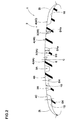
Fig. 1 is a development view of a tread portion of a pneumatic tire of an embodiment of the present invention. -
Fig. 2 is a cross sectional view taken along the line A-A ofFig. 1 . -
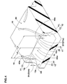
Fig. 3 is a partial enlarged view ofFig. 1 . -
Fig. 4 is a partial perpendicular view of a middle land portion. -
Fig. 5 is a partial perpendicular view of a middle land portion of another embodiment. -
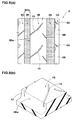
Fig. 6a is a plane view of a mi ddl e land portion of a comparative example 1; andFig. 6b is a partial perpendicular view ofFig. 6a . -
Fig. 7a is a pl ane view of a middle land portion of a comparative example 2; andFig.7b is a partial perpendicular view ofFig. 7a . -
Fig. 8a is a plane view of a middle land portion of an example 8; andFig. 8b is a partial perpendicular view ofFig. 8a . - One embodiment of the present invention will be described below with reference to the drawings.
- As shown in
Figs. 1 and2 , a pneumatic tire 1 of the present embodiment (hereinafter, also referred to simply as "tire") is suitably used for passenger cars, for example. The tire 1 has atread portion 2 with at least two circumferentially and continuously extendinglongitudinal grooves 3 and at least oneland portion 4 between thelongitudinal grooves 3. In this embodiment, thetread portion 2 has a non-designated rotational direction pattern. - The
longitudinal grooves 3 of the present embodiment comprise a pair of centerlongitudinal grooves 3A disposed on both side of a tire equator C and a pair of shoulderlongitudinal grooves 3B disposed axially outside the centerlongitudinal grooves 3A. - The center
longitudinal groove 3A and the shoulderlongitudinal grooves 3B extend in a straight form along the circumferential di rection of the tire. The thus configured straight longitudinal grooves can improve drainage performance by smoothly di schargi ng water between the tread portion and road surface through thelongitudinal grooves 3 to backward in the direction of rotation of the tire. The maximum groove widths W1a and W1b of the centerlongitudinal groove 3A and the shoulderlongitudinal grooves 3B are preferably set in a range of from 3 to 10% of the tread contact width TW, and the maximum groove depths D1a and D1b are preferably set in a range of from 6 to 10 mm. - The tread contact width TW is a distance between the
tread edges - Here, the
tread edges 2t are the axial outermost edges of the ground contacting patch of the tread portion at a camber angle of zero degree in a standard loaded condition that the tire is mounted on a standard wheel rim and inflated to a standard pressure and loaded with a standard load. - The standard wheel rim is a wheel rim officially approved for the tire by standard organization, i.e. JATMA, T&RA, ETRTO and the like. The standard rim is the "standard rim" specified in JATMA, the "Measuring Rim" in ETRTO, the "Design Rim" in TRA or the like.
- The standard pressure is an air pressure for tire specified by the standard organization above. For example, the standard pressure is the "maximum air pressure" in JATMA, the "Inflation Pressure" in ETRTO, the maximum pressure given in the "Tire Load Limits at various cold Inflation Pressures" table in TRA or the like. In case of passenger car tires, however, the standard pressure is uniformly defined by 180 kPa.
- The standard load is a tire load specified by the standard organization above. For example, the standard load is the "maximum load capacity" in JATMA, the "Load Capacity" in ETRTO, the maximum value given in the above-mentioned table in TRA or the like.
- Dimensions and the like of parts of the ti re have val ues under a standard unloaded condi ti on that the ti re is mounted on the standard wheel rim and inflated to the standard pressure but loaded with no tire load, unless otherwise stated.
- Moreover, the maximum groove width w1a of the center
longitudinal groove 3A is preferably formed larger than the maximum groove width w1b of the shoulderlongitudinal groove 3B. Accordingly, the centerlongitudinal grooves 3A can effectively discharge a water film between thetread portion 2 near the ti re equator C and the load surface, thereby improving drainage performance. Meanwhile, the shoulderlongitudinal grooves 3B can decrease air columns passing therethrough to reduce air column resonance, thereby improving noise resistance. - If the ratio (W1a/W1b) of the maximum groove width w1a of the center
longitudinal grooves 3A and the maximum groove width w1b of the shoulderlongitudinal grooves 3B is small, a water film between thetread portion 2 near the tire equator C and the road surface may not be sufficiently discharged. In contrast, if the ratio (W1a/W1b) is larger, air columns passing through the shoulderlongitudinal grooves 3B may not be sufficiently decreased. From this point of view, the ratio (W1a/W1b) is preferably 1.5 or more, more preferably 1.6 or more, and is preferably 1.8 or less, more preferably 1.7 or less. - The
land portion 4 includes acenter land portion 4A between centerlongitudinal grooves middle land portions 4B between the centerlongitudinal groove 3A and the shoulderlongitudinal groove 3B, and a pair ofshoulder land portions 4C between the shoulderlongitudinal groove 3B and thetread edge 2t. - The
center land portion 4A is formed as a rib which circumferentially and continuously extends between the centerlongitudinal grooves center land portion 4A is not divided by a lateral grooves passing over the entire width of thecenter land portion 4A. - The
center land portion 4A can effectively enhance circumferential rigidity and improve straight-ahead driving stability. Preferably, a maximum width W2a of thecenter land portion 4A in a tire axial direction is desirably about 8 to 15% of the tread contact width TW. - In addition, the
center land portion 4A is provided with a circumferentially and continuously extendingcenter sub-groove 6, andcenter sipes 8A extending with inclination from both edges of thecenter land portion 4A toward the ti re equator C. Chamferededges 7 are provided at acute-angled corners between thecenter sipes 8A and the both edges of thecenter land portion 4A. - The
center sub-groove 6 extends circumferentially and continuously on the tire equator C. Thecenter sub-groove 6 can effectively discharge a water film between thecenter land portion 4A and the road surface, thereby enhancing drainage performance. Preferably, a groove width W3 of thecenter sub-groove 6 is about 5 to 15% of the maximum width W2a of thecenter land portion 4A, and a groove depth D3 of the center sub-groove (shown inFig. 2 ) is desirably about 1 to 4 mm. - The
center sipes 8A each extend with inclination from the both edges of thecenter land portion 4A and terminate without reaching thecenter sub-groove 6. In addition, thecenter sipes 8A each are inclined at an angle α1a of about 40 to 60 degrees with respect to the circumferential direction of the tire, and are alternately arranged in the circumferential direction of the tire on the both edges of thecenter land portion 4A. Thecenter sipes 8A can effectively discharge a water film between thecenter land portion 4A and the road surface while suppressing deterioration in rigidity at thecenter land portion 4A. - The
chamfered edges 7 are formed by denting a tread surface of thecenter land portion 4A in an approximate triangular shape in a planar view, ranging from thecenter sipes 8A toward the centerlongitudinal grooves 3A. In addition, the chamferededges 7 are alternately arranged in the circumferential direction of the tire at the both edges of thecenter land portion 4A. The chamfered edges 7 can suppress occurrence of damage such as tipping at the acute-angled corners between thecenter sipes 8A and the both edges of thecenter land portions 4A. The chamfered edges 7 can also effectively suppress generation of noises due to air column resonance by disturbing vibration of air columns formed between the centerlongitudinal grooves 3A and the road surface, thereby improving noise resistance. - The
middle land portions 4B are also formed as a rib which circumferentially and continuously extends between the centerlongitudinal grooves 3A and the shoulderlongitudinal grooves 3B. Themiddle land portions 4B can suppress an amount of lateral deformation at cornering and improve steering stability performance. Preferably, a maximum width W2b of themiddle land portions 4B is about 10 to 18% of the tread contact width TW. - In addition, the
middle land portions 4B are each provided withmiddle sipes 8B extending with inclination from the centerlongitudinal groove 3A outwardly in the tire axial direction, andlateral grooves 10 each including one end communicating with the shoulderlongitudinal groove 3B and the other end extending with inclination toward the tire equator C. In this embodiment, themiddle sipes 8B and thelateral grooves 10 are alternately arranged in the circumferential direction of the tire on the both edges of themiddle land portions 4B. - The
middle sipes 8B each extend with inclination from the centerlongitudinal grooves 3A outwardly in the ti re axial direction and terminate without reaching the shoulderlongitudinal grooves 3B. In addition, an angle α1b formed by themiddle sipes 8B with respect to the circumferential direction of the tire is set at about 30 to 60 degrees. The thus configuredmiddle sipes 8B can enhance drainage performance while suppressing deterioration in rigidity of themiddle land portions 4B. - The
lateral grooves 10 each extend with inclination in the opposite direction of themiddle sipes 8B with respect to the circumferential direction of the tire, and include one end communicating with the shoulderlongitudinal groove 3B and the other end terminating without reaching the centerlongitudinal grooves 3A. The thus configuredlateral grooves 10 can smoothly guide a water film between themiddle land portions 4B and the road surface, to the shoulderlongitudinal grooves 3B, thereby enhancing drainage performance. - To effectively enhance the foregoing drainage performance, an angle α4 formed by the
lateral grooves 10 with respect to the circumferential di recti on of the tire is desirably 30 to 60 degrees. If the angle α4 exceeds 60 degrees, water films between themiddle land portions 4B and the road surface may not be guided smoothly. In contrast, if the angle α4 is less than 30 degrees, thelateral grooves 10 are excessively inclined toward the circumferential direction of the tire, and rigidity of themiddle land portions 4B may not be sufficiently maintained, thereby resulting in occurrence of uneven wear. From this point of view, the angle α4 is more preferably 50 degrees or less, and is more preferably 40 degrees or more. - From the same point of view, the groove width W4 of the
lateral grooves 10 is desirably set from 1.0 to 2.0 mm. If the groove width W4 is less than 1.0 mm, water films between themiddle land portions 4B and the road surface may not be sufficiently discharged. In contrast, if the groove width W4 exceeds 2.0 mm, ri gi di ty of the mi ddl eland portions 4B may not be sufficiently maintained. - Further, a groove depth D4 (shown in
Fig. 2 ) of thelateral grooves 10 is preferably 65% or more of the maximum groove depth D1b of the shoulderlongitudinal grooves 3B, and is preferably 90% or less of the same. - In this embodiment, as shown in the enlarged view of
Fig. 3 , in each section of a groove wall 3Bw of the shoulderlongitudinal groove 3B, between thelateral grooves middle land portion 4B, adent portion 11 and a protrudedportion 12 are provided. - The
dent portion 11 is formed the nearest side of the tire equator C. The protrudedportion 12 protrudes with inclination from thedent portions 11 toward one of thelateral grooves 10 in the circumferential direction of the tire so as to gradually reduce a width of the shoulderlongitudinal groove 3B. On the other hand, the groove wall of the shoulderlongitudinal groove 3B on thetread edge 2t si de extends circumferentially and continuously in a straight shape. - The thus configured protruded
portion 12 allows the groove wall 3Bw of the shoulderlongitudinal groove 3B to be irregularly shaped with dents and protrusions in a planar view, thereby disturbing vibration of air columns formed between the shoulderlongitudinal grooves 3B and the road surface. Therefore, thedent portions 11 and the protrudedportions 12 can effectively suppress generation of noises due to air column resonance at the shoulderlongitudinal grooves 3B, thereby improving noise resistance. - Each
dent portion 11 in this embodiment is formed by amain surface 16 and aslant surface 17. Themain surface 16 rises from a groove bottom of the shoulderlongitudinal groove 3B and extends in the circumferential direction of the tire. Theslant surface 17 connects between anouter edge 16e of themain surface 16 and an edge 4Be of a ground contact surface of themiddle land portion 4B. The slant surfaces 17 can increase a groove volume of the shoulderlongitudinal grooves 3B to thereby improve drainage performance and disturb vibration of air columns formed between the shoulderlongitudinal grooves 3B and the road surface to thereby improve noise resistance. - In addition, the
slant surface 17 in this embodiment each has a width W7 in the tire axial direction and a length D7 in the tire radial direction, two of which gradually increase from the protrudedportion 12 side toward the otherlateral groove 10. The thus configured slant surfaces 17 can smooth out great rigidity variations that are apt to be formed at themiddle land portions 4B, by acute-angled corners 19 between the otherlateral groove 10 and the shoulderlongitudinal groove 3B, thereby preventing generation of uneven wear. - To ensure compatibility between the drainage performance and the noise resistance, the ratio (W7m/W1b) between a maximum length w7m of the slant surfaces 17 in the tire axial direction and the maximum groove width w1b of the shoulder
longitudinal grooves 3B is desirably 10 to 30%. If the ratio (W7m/W1b) is less than 10%, sufficient disturbance may not be generated in vibration of air columns formed between the shoulderlongitudinal grooves 3B and the road surface. In contrast, if the ratio (W7m/W1b) exceeds 30%, themiddle land portions 4B may be excessively deteriorated in rigidity. From this point of view, the ratio (W7m/W1b) is more preferably 15% or more, and is more preferably 25% or less. - From the same point of view, the ratio (D7m/D1b) between a maximum length D7m of the
sl ant surface 14 in the ti re radi us direction and a maximum groove depth D1b (shown inFIG. 2 ) of the shoulderlongitudinal grooves 3B is preferably 35% or less, more preferably 30% or less, and is preferably 15% or more, more preferably 20% or more. - The protruded
portions 12 in this embodiment are formed at the shoulderlongitudinal grooves 3B. In general, the shoulderlongitudinal grooves 3B have larger influence on pass-by noises of vehicles as compared to the centerlongitudinal grooves 3A. Therefore, in this embodiment, the protrudedportions 12 can effectively improve noise resistance. Meanwhile, the centerlongitudinal grooves 3A do not have the protrudedportions 12 and therefore suppress deterioration in drainage performance. As a matter of course, the protrudedportions 12 can be formed at the centerlongitudinal grooves 3A. - To effectively provide the noise resistance, the ratio (L5m/W1b) between a maximum length L5m of the protruded
portions 12 in the tire axial direction and the maximum groove width W1b of the shoulderlongitudinal grooves 3B is desirably 10 to 30%. If the ratio (L5m/W1b) is less than 10%, sufficient disturbance may not be generated in vibration of air columns formed between the shoulderlongitudinal groove 3B and the road surface. In contrast, if the ratio (L5m/W1b) exceeds 30%, the shoulderlongitudinal grooves 3B become small in groove volume, which may result in deterioration of drainage performance. From this point of view, the ratio (L5m/W1b) is more preferably 15% or more, and is more preferably 25% or less. - In addition, the protruded
portions 12 in this embodiment are each formed by amain surface 13 and aslant surface 14. Themain surface 13 rises from a groove bottom of the shoulderlongitudinal groove 3B. Theslant surface 14 connects between anouter edge 13e of themain surface 13 and an edge 4Be of a ground contact surface of themiddle land portion 4B and has an inclined angle larger than that of themain surface 13. - The thus configured slant surfaces 14 can minimize influence of reduction in groove volume of the shoulder
longitudinal grooves 3B due to presence of the protrudedportions 12, thereby preventing deterioration in drainage performance. In addition, the slant surfaces 14 can suppress grounding of the protrudedportions 12, whi ch makes ri gi di ty of the middleland porti ons 4B approach a uni form level in the circumferential direction, thereby preventing generation of uneven wear. - Further, together with the slant surfaces 17 of the
dent portions 11, the slant surfaces 14 of the protrudedportions 12 can suppress deterioration in rigidity of themiddle land portions 4B on both sides of intersections between thelateral grooves 10 and the shoulderlongitudinal grooves 3B in the circumferential direction of the tire, and can make rigidity of themiddle land portions 4B further approach a uniform level in the circumferential di recti on of the tire, thereby effectively preventing generation of uneven wear. - The slant surfaces 14 in this embodiment each have a width W5 in the tire axial direction and a length D5 in the tire radius direction, two of which gradually increase from the
dent portion 11 side toward one of thelateral grooves 10. Accordingly, the slant surfaces 14 can gradually increase the width W5 with increase in the length L5 of the protrudedportions 12 in the tire axial direction, thereby making circumferential rigidity of themiddle land portions 4B further approach a uniform level and improving uneven wear resistance. - To effectively produce the foregoing effects, the maximum width w5m of the slant surfaces 14 is desirably set within the same range of the maximum length L5m of the protruded
portions 12. - In addition, the ratio (D5m/D1b) between the maximum length D5m of the slant surfaces 14 in the tire radius direction and the maximum groove depth D1b (shown in
Fig. 2 ) of the shoulderlongitudinal grooves 3B is desirably 15 to 35%. If the ratio (D5m/D1b) is less than 15%, drainage performance may not be sufficiently improved. In contrast, if the ratio (D5m/D1b) exceeds 35%, sufficient disturbance may not be generated in vibration of air columns formed between the shoulderlongitudinal grooves 3B and the road surface. From this point of view, the ratio (D5m/D1b) is more preferably 20% or more, and is more preferably 30% or less. - Further, to form the
dent portions 11 and the protrudedportions 12 in a balanced manner, the ratio (L6/L7) between a circumferential length L6 on the tread ground contact surface from one of thelateral grooves 10 to aboundary 15 between thedent portion 11 and the protrudedportion 12 and a circumferential length L7 between thelateral grooves - If the ratio (L6/L7) is less than 0.33, the protruded
portions 12 become smaller and sufficient disturbance may not be generated in vibration of ai r columns formed between the shoulderlongitudinal grooves 3B and the road surface. Further, themiddle land portions 4B may become uneven in circumferential rigidity, thereby generating uneven wear. In contrast, if the ratio (L6/L7) exceeds 0.67, the protrudedportions 12 become larger, which may deteriorate drainage performance. From this point of view, the ratio (L6/L7) is more preferably 0.4 or more, and is more preferably 0.6 or less. -
Fig. 5 shows adent portion 11 and protrudedportions 12 in another embodiment. - The protruded
portions 12 in this embodiment are formed on the both sides of thedent portion 11 between thelateral grooves dent portion 11 constitutes a ridge line formed by intersection of the protrudedportions - The thus configured protruded
portions longitudinal grooves 3B to be further irregularly shaped, and generate disturbance in vibration of air columns formed between the shoulderlongitudinal grooves 3B and the road surface. In addition, the protrudedportions 12 each have amain surface 13 and aslant surface 14 as in the previous embodiment, thereby preventing deterioration in drainage performance. - As shown in
Fig. 1 , theshoulder land portions 4C are formed as rib bodies extending circumferentially and continuously between the shoulderlongitudinal grooves 3B and the tread edges 2t. The thus configuredshoulder land portions 4C can suppress an amount of deformation in the lateral direction at cornering and improve cornering performance. Preferably, the maximum width W2c of theshoulder land portions 4C is desirably about 15 to 25% of the tread contact width TW. - In addition, the
shoulder land portions 4C are each provided with theshoulder sipes 8C extending with gradual inclination from the shoulderlongitudinal groove 3B outwardly in the tire axial direction and terminating without reaching thetread edge 2t; andshoulder lug grooves 18 extending with gradual inclination from thetread edge 2t inwardly in the tire axial direction and terminating without reaching the shoulderlongitudinal groove 3B. - The
shoulder sipes 8C and theshoulder lug grooves 18 are alternately arranged in the circumferential direction of the tire at theshoulder land portions 4C and can discharge smoothly water films between theshoulder land portions 4C and the road surface. Preferably, the angle α1c formed by theshoulder sipes 8C with respect to the tire circumferential di rection is about 50 to 90 degrees, and a groove width w6 of theshoulder lug grooves 18 is about 3 to 7 mm, and a groove depth D6 (shown inFig. 2 ) of theshoulder lug grooves 18 is about 5 to 9 mm. - As in the foregoing, a preferred embodiment of the present invention is described above. However, the present invention is not limited to the illustrated embodiment, and can be modified and carried out in various manners.
- Tires having a basic structure shown in
Fig. 1 were manufactured with protruded portions and dent portions shown in Table 1, and were evaluated for performance. In addition, the following comparative examples were evaluated in the same manner: a tire including a middle land portion with no protruded portion or dent portion shown inFig. 6 (comparative example 1); a tire including a middle land portion with no slant surface at protruded portions or at dent portions shown inFig. 7 (comparative example 2); a tire including a middle land porti on in whi ch a width and a radi us length of a slant surface do not gradually increase shown inFig. 8 (comparative example 8). Common specifications are as follows: - Tire size: 225/60 R18
- Rim size: 18 x 7.0 J
- Tread contact width TW: 182 mm
- Maximum groove depth D1a of the center longitudinal groove: 8.5 mm
- Maximum groove depth D1b of the shoulder longitudinal groove: 8.5 mm
- Center sub-groove:
- Groove width W3: 2 mm, groove depth D3: 2 mm
- Center land portion:
- Maximum width W2a: 20 mm, ratio (W2a/TW): 11.0% Groove depth D4 of the lateral groove: 7.0 mm
- Shoulder land portion:
- Maximum width W2c: 37 mm, ratio (W2c/TW): 20.3% shoulder lag groove:
- Groove width w6: 4.8 mm
- Groove depth D6: 6.4 mm
- Maximum width W2c: 37 mm, ratio (W2c/TW): 20.3% shoulder lag groove:
- Test procedures are as follows:
- In the test, test tires mounted on rims with an internal air pressure of 210 kPa were attached to 2400 cc FF-type Japanese passenger car. The test car was run on a wet asphalt road with 5 mm depth of water and sharply braked at a speed of 100 km/hr so that the ABS worked. The braking distance of each tires were measured. The results are shown with an index of 100 representing a value in comparative example 1. The larger the value, the better the performance.
- The foregoing test car was run at a speed of 100 km/hr on a smooth road, and then the pattern noise during the run was evaluated in a feeling test by a test driver. The results are shown in an index of 100 representing a value in comparative example 1. The larger the value, the better the performance.
- The foregoing test car was run on a dry asphalt road for 8,000 km, and then the uneven wear on the middle portion that is the wear differences between the axially inner edge and the axially outer edge of the middle land portion were measured. The uneven wear were measured at three points in the circumferential direction of the tire, and the average values of uneven wear were calculated. The results are shown in an index of 100 representing a value in comparative example 1. The larger the value, the better the performance.
- The results of the Tests are shown in Table 1.
Table 1 Comparative example 1 Comparative example 2 Example 1 Example 2 Example 3 Example 4 Example 5 Example 6 Example 7 Example 8 Example 9 Example 10 Example 11 Example 12 Example 13 Perpendicular view of middle land portion Fig. 6 Fig. 7 Fig. 4 Fig. 4 Fig. 4 Fig. 4 Fig. 4 Fig. 4 Fig. 4 Fig. 8 Fig. 4 Fig. 4 Fig. 4 Fig. 4 Fig. 5 Maximum groove width W1a of center longitudinal groove (mm) 12.5 12.5 12.5 12 13 12.5 12.5 12.5 12.5 12.5 12.5 12.5 12.5 12.5 12.5 Maximum groove width W1b of shoulder longitudinal groove (mm) 7.8 7.8 7.8 8.0 7.2 7.8 7.8 7.8 7.8 7.8 7.8 7.8 7.8 7.8 7.8 Ratio (W1a/W1b) (times) 1.60 1.60 1.60 1.50 1.81 1.60 1.60 1.60 1.60 1.60 1.60 1.60 1.60 1.60 1.60 Angle α4 of lateral groove (degrees) 50 50 50 50 50 60 30 50 50 50 50 50 50 50 50 Maximum length L5m of protruded portion (mm) - 1.5 1.5 1.5 1.5 1.5 1.5 0.8 2.3 1.5 1.5 1.5 1.5 1.5 1.5 Ratio (L5m/W1b) (%) - 19.2 19.2 18.8 20.8 19.2 19.2 10.3 29.5 19.2 19.2 19.2 19.2 19.2 19.2 Maximum length D5m of slant surface of protruded portion (mm) - - 2.5 2.5 2.5 2.5 2.5 2.5 2.5 2.5 1.3 3.0 2.5 2.5 2.5 Ratio (D5m/D1b) (%) - - 29.4 29.4 29.4 29.4 29.4 29.4 29.4 29.4 15 35 29.4 29.4 29.4 Maximum length D7m of slant surface of dent portion (mm) - - 2.5 2.5 2.5 2.5 2.5 2.5 2.5 2.5 1.3 3.0 2.5 2.5 - Ratio (D7m/D1b) (%) - - 29.4 29.4 29.4 29.4 29.4 29.4 29.4 29.4 15 35 29.4 29.4 - Length L6 from one lateral groove to boundary (mm) - - 15 15 15 15 15 15 15 15 15 15 10 20 15 Length L7 between lateral grooves (mm) - - 30 30 30 30 30 30 30 30 30 30 30 30 30 Ratio (L6/L7) (times) - - 0.50 0.50 0.50 0.50 0.50 0.50 0.50 0.50 0.50 0.50 0.33 0.67 0.50 Drainage performance (index) [Larger values are better] 100 80 110 105 115 103 115 112 108 105 104 113 110 108 106 Noise resistance (index) [Larger values are better] 100 110 115 117 110 112 115 111 118 116 116 111 106 115 116 Uneven wear resistance (index) [Larger values are better] 100 90 100 100 100 105 98 100 98 92 100 100 105 100 96 - As the result of the test, it has been confirmed that examples according to the present invention are improved in the noise performance while keeping the drainage performance and uneven wear resistance.
Claims (10)
- A pneumatic tire comprising
a tread portion,
at least two circumferentially and continuously extending longitudinal grooves being provided with the tread portion,
at least one land portion divided between the longitudinal grooves,
a plurality of lateral grooves being provided with the land portion,
said each lateral grooves having one end communicating with one of the longitudinal grooves and the other end extending toward a tire equator,
said longitudinal groove having a groove wall to which said lateral grooves are connected,
in each section between lateral grooves adjacent to a circumferential direction of the tire, said groove wall having at least one protruded portion and a dent portion being formed the nearest side of the tire equator,
the protruded portion inclined with respect to the circumferential direction of the tire so as to gradually reduce a width of the longitudinal groove toward at least one lateral groove, and
in a cross section of the groove wall, the protruded portion comprising
a main surface which extends radially outside from the groove bottom of the longitudinal groove and
a slant surface extending from a radially outer edge of the main surface to a ground contact surface of the land porti on and having an inclined angle larger than that of the main surface. - The pneumatic tire according to claim 1, wherein
the slant surface has a width in the axial direction of the tire, and
the width of the slant surface gradually increases toward at least one lateral groove. - The pneumatic tire according to claim 1 or 2, wherein
the slant surface has a height in the radial direction of the tire, and
the height of the slant surface gradually increases toward at least one lateral groove. - The pneumatic tire according to claim 1, wherein
in a cross section of the groove wall, the dent portion comprises
a main surface which extends radially outside from the groove bottom of the longitudinal groove and
a slant surface which extends from a radially outer edge of the main surface to the ground contact surface of the land portion, and
the slant portion has an inclined angle larger than that of the main surface. - The pneumatic tire according to claim 4, wherein
the main surface of the dent portion extends in the circumferential direction of the tire. - The pneumatic tire according to claim 1 or 2, wherein
the groove wall has a boundary between the dent portion and the protruded portion, and
a circumferential length of the boundary from one of the lateral grooves is in a range of from 0.33 to 0.67 times of a circumferential length between lateral grooves adjacent to a circumferential direction of the tire. - The pneumatic tire according to claim 1 or 2, wherein
said lateral grooves have a width of from 1.0 to 2.0 mm and an inclination angle of 30 to 60 degrees with respect to the axial direction of the tire. - The pneumatic tire according to claim 1 or 2, wherein
said longitudinal grooves include a pair of center longitudinal grooves disposed on both side of the tire equator and a pair of shoul der longitudinal grooves di sposed axially outsi de the center longitudinal grooves, and
a width of the center longitudinal groove is in a range of from 1.5 to 1.8 times of a width of the shoulder longitudinal groove. - The pneumatic tire according to claim 8, wherein
the land portion is a middle land portion which is formed between the shoulder longitudinal groove and the center longitudinal groove, and
the protruded portion and the dent portion are provided on a groove wall of the shoulder longitudinal groove. - The pneumatic tire according to claim 1 or 2, wherein
in each section between lateral grooves adjacent to a circumferential direction of the tire, the groove wall has two protruded portions and one said dent portion disposed therebetween.
Applications Claiming Priority (1)
| Application Number | Priority Date | Filing Date | Title |
|---|---|---|---|
| JP2011136546A JP5337201B2 (en) | 2011-06-20 | 2011-06-20 | Pneumatic tire |
Publications (3)
| Publication Number | Publication Date |
|---|---|
| EP2537688A2 true EP2537688A2 (en) | 2012-12-26 |
| EP2537688A3 EP2537688A3 (en) | 2014-05-21 |
| EP2537688B1 EP2537688B1 (en) | 2015-07-08 |
Family
ID=46168187
Family Applications (1)
| Application Number | Title | Priority Date | Filing Date |
|---|---|---|---|
| EP12168874.1A Not-in-force EP2537688B1 (en) | 2011-06-20 | 2012-05-22 | Pneumatic tire |
Country Status (5)
| Country | Link |
|---|---|
| US (1) | US9038683B2 (en) |
| EP (1) | EP2537688B1 (en) |
| JP (1) | JP5337201B2 (en) |
| KR (1) | KR101788883B1 (en) |
| CN (1) | CN102837564B (en) |
Cited By (8)
| Publication number | Priority date | Publication date | Assignee | Title |
|---|---|---|---|---|
| EP2781373A1 (en) * | 2013-03-19 | 2014-09-24 | Sumitomo Rubber Industries, Ltd. | Pneumatic tire |
| CN105636802A (en) * | 2013-10-22 | 2016-06-01 | 住友橡胶工业株式会社 | Pneumatic tire |
| EP3305552A4 (en) * | 2015-06-08 | 2018-06-13 | Bridgestone Corporation | Tire |
| US10023012B2 (en) | 2014-01-15 | 2018-07-17 | Bridgestone Corporation | Tire |
| EP3575111A1 (en) * | 2018-05-31 | 2019-12-04 | Sumitomo Rubber Industries, Ltd. | Pneumatic tyre |
| EP3656580A1 (en) * | 2015-02-04 | 2020-05-27 | Bridgestone Corporation | Pneumatic tire |
| EP3643526A4 (en) * | 2017-06-19 | 2021-03-03 | Bridgestone Corporation | PNEUMATIC |
| US20210331524A1 (en) * | 2020-04-28 | 2021-10-28 | Toyo Tire Corporation | Pneumatic tire |
Families Citing this family (29)
| Publication number | Priority date | Publication date | Assignee | Title |
|---|---|---|---|---|
| ITTO20110471A1 (en) * | 2011-05-30 | 2012-12-01 | Bridgestone Corp | METHOD FOR DETERMINING THE LONGITUDINAL STEP OF THE BLOCKS OF A TREAD STRIP |
| USD683694S1 (en) * | 2011-09-27 | 2013-06-04 | Toyo Tire & Rubber Co., Ltd. | Automobile tire |
| USD683302S1 (en) * | 2011-11-18 | 2013-05-28 | Toyo Tire & Rubber Co., Ltd. | Tire |
| USD684108S1 (en) * | 2011-11-18 | 2013-06-11 | Toyo Tire & Rubber Co., Ltd. | Tire |
| JP5834046B2 (en) * | 2013-05-21 | 2015-12-16 | 住友ゴム工業株式会社 | Pneumatic tire |
| JP6002182B2 (en) * | 2014-08-12 | 2016-10-05 | 住友ゴム工業株式会社 | Pneumatic tire |
| JP6231974B2 (en) * | 2014-11-27 | 2017-11-15 | 住友ゴム工業株式会社 | Pneumatic tire |
| JP6084195B2 (en) * | 2014-11-27 | 2017-02-22 | 住友ゴム工業株式会社 | Pneumatic tire |
| JP6393208B2 (en) * | 2015-02-16 | 2018-09-19 | 住友ゴム工業株式会社 | Pneumatic tire |
| JP6484069B2 (en) * | 2015-03-05 | 2019-03-13 | 住友ゴム工業株式会社 | Pneumatic tire |
| JP6445916B2 (en) * | 2015-04-01 | 2018-12-26 | 株式会社ブリヂストン | tire |
| USD764392S1 (en) * | 2015-06-10 | 2016-08-23 | Cooper Tire & Rubber Company | Tire tread |
| JP6575254B2 (en) * | 2015-09-15 | 2019-09-18 | 住友ゴム工業株式会社 | Pneumatic tire |
| FR3042738B1 (en) * | 2015-10-27 | 2017-11-24 | Michelin & Cie | PNEUMATIC WORKING LAYER COMPRISING MONOFILAMENTS AND GROOVED ROLLING BELT |
| USD793950S1 (en) * | 2015-12-14 | 2017-08-08 | Cooper Tire & Rubber Company | Tire tread |
| WO2017112504A1 (en) * | 2015-12-22 | 2017-06-29 | Bridgestone Americas Tire Operations, Llc | Tire having exposed three dimensional sipe patterns |
| JP6388013B2 (en) * | 2016-10-26 | 2018-09-12 | 横浜ゴム株式会社 | Pneumatic tire |
| JP6374996B2 (en) * | 2017-01-24 | 2018-08-15 | 住友ゴム工業株式会社 | Pneumatic tire |
| JP6891556B2 (en) * | 2017-03-14 | 2021-06-18 | 住友ゴム工業株式会社 | tire |
| JP7013765B2 (en) * | 2017-09-22 | 2022-02-15 | 横浜ゴム株式会社 | Pneumatic tires |
| JP6929189B2 (en) * | 2017-10-13 | 2021-09-01 | Toyo Tire株式会社 | Pneumatic tires |
| JP7091897B2 (en) * | 2018-07-12 | 2022-06-28 | 住友ゴム工業株式会社 | tire |
| JP7144279B2 (en) * | 2018-10-22 | 2022-09-29 | Toyo Tire株式会社 | pneumatic tire |
| CN111619290B (en) * | 2019-02-28 | 2024-03-22 | 住友橡胶工业株式会社 | Tire with a tire body |
| USD931789S1 (en) * | 2019-04-22 | 2021-09-28 | Toyo Tire Corporation | Tire |
| USD931788S1 (en) * | 2019-04-22 | 2021-09-28 | Toyo Tire Corporation | Tire |
| DE112020005271B9 (en) * | 2019-12-13 | 2025-04-17 | The Yokohama Rubber Co., Ltd. | Tires |
| JP7074120B2 (en) * | 2019-12-26 | 2022-05-24 | 住友ゴム工業株式会社 | tire |
| EP4026688A1 (en) | 2021-01-07 | 2022-07-13 | Maschinenfabrik Bermatingen GmbH & Co. KG | Baler and method for operating the same |
Family Cites Families (14)
| Publication number | Priority date | Publication date | Assignee | Title |
|---|---|---|---|---|
| US4690189A (en) * | 1986-01-29 | 1987-09-01 | The Goodyear Tire & Rubber Company | All-season pneumatic tire with chamfered tread blocks |
| JPH0776205A (en) * | 1993-09-08 | 1995-03-20 | Toyo Tire & Rubber Co Ltd | Heavy duty radial tire |
| IT1276320B1 (en) * | 1994-02-22 | 1997-10-28 | Pirelli | TIRE FOR MEDIUM / HEAVY TRANSPORT VEHICLES WITH UNIVERSAL TYPE TREAD |
| JPH1086610A (en) * | 1996-09-17 | 1998-04-07 | Bridgestone Corp | Pneumatic tire for heavy load |
| JP4059592B2 (en) * | 1998-05-28 | 2008-03-12 | 横浜ゴム株式会社 | Pneumatic tire |
| JP4331345B2 (en) * | 1999-09-08 | 2009-09-16 | 株式会社ブリヂストン | Pneumatic tire with directional pattern |
| JP4015573B2 (en) * | 2003-02-28 | 2007-11-28 | 住友ゴム工業株式会社 | Pneumatic tire |
| JP4420623B2 (en) * | 2003-05-28 | 2010-02-24 | 株式会社ブリヂストン | Pneumatic tire |
| JP4276614B2 (en) * | 2004-11-25 | 2009-06-10 | 住友ゴム工業株式会社 | Pneumatic tire |
| JP4537952B2 (en) | 2005-12-27 | 2010-09-08 | 住友ゴム工業株式会社 | Pneumatic tire |
| AU2007335551B2 (en) * | 2006-12-20 | 2011-04-14 | Bridgestone Corporation | A pneumatic tire |
| KR101154773B1 (en) * | 2007-05-14 | 2012-06-18 | 가부시키가이샤 브리지스톤 | Pneumatic tire |
| JP4280297B2 (en) * | 2007-10-03 | 2009-06-17 | 住友ゴム工業株式会社 | Pneumatic tire |
| JP4697336B2 (en) * | 2009-02-20 | 2011-06-08 | 横浜ゴム株式会社 | Pneumatic tire |
-
2011
- 2011-06-20 JP JP2011136546A patent/JP5337201B2/en not_active Expired - Fee Related
-
2012
- 2012-05-22 US US13/477,782 patent/US9038683B2/en not_active Expired - Fee Related
- 2012-05-22 EP EP12168874.1A patent/EP2537688B1/en not_active Not-in-force
- 2012-06-12 CN CN201210193402.9A patent/CN102837564B/en not_active Expired - Fee Related
- 2012-06-12 KR KR1020120062544A patent/KR101788883B1/en not_active Expired - Fee Related
Non-Patent Citations (1)
| Title |
|---|
| None |
Cited By (16)
| Publication number | Priority date | Publication date | Assignee | Title |
|---|---|---|---|---|
| US9802443B2 (en) | 2013-03-19 | 2017-10-31 | Sumitomo Rubber Industries, Ltd. | Pneumatic tire |
| EP2781373A1 (en) * | 2013-03-19 | 2014-09-24 | Sumitomo Rubber Industries, Ltd. | Pneumatic tire |
| CN105636802A (en) * | 2013-10-22 | 2016-06-01 | 住友橡胶工业株式会社 | Pneumatic tire |
| EP3053760A4 (en) * | 2013-10-22 | 2017-06-14 | Sumitomo Rubber Industries, Ltd. | Pneumatic tire |
| CN105636802B (en) * | 2013-10-22 | 2018-10-30 | 住友橡胶工业株式会社 | Pneumatic tire |
| US10427469B2 (en) | 2013-10-22 | 2019-10-01 | Sumitomo Rubber Industries, Ltd. | Pneumatic tire |
| US10889150B2 (en) | 2013-10-22 | 2021-01-12 | Sumitomo Rubber Industries, Ltd. | Pneumatic tire |
| US10023012B2 (en) | 2014-01-15 | 2018-07-17 | Bridgestone Corporation | Tire |
| EP3095620B1 (en) * | 2014-01-15 | 2018-09-12 | Bridgestone Corporation | Tire |
| EP3656580A1 (en) * | 2015-02-04 | 2020-05-27 | Bridgestone Corporation | Pneumatic tire |
| EP3305552A4 (en) * | 2015-06-08 | 2018-06-13 | Bridgestone Corporation | Tire |
| EP3643526A4 (en) * | 2017-06-19 | 2021-03-03 | Bridgestone Corporation | PNEUMATIC |
| EP3575111A1 (en) * | 2018-05-31 | 2019-12-04 | Sumitomo Rubber Industries, Ltd. | Pneumatic tyre |
| US11312183B2 (en) | 2018-05-31 | 2022-04-26 | Sumitomo Rubber Industries, Ltd. | Pneumatic tyre |
| US20210331524A1 (en) * | 2020-04-28 | 2021-10-28 | Toyo Tire Corporation | Pneumatic tire |
| US12059928B2 (en) * | 2020-04-28 | 2024-08-13 | Toyo Tire Corporation | Pneumatic tire |
Also Published As
| Publication number | Publication date |
|---|---|
| JP2013001326A (en) | 2013-01-07 |
| KR20120140200A (en) | 2012-12-28 |
| CN102837564B (en) | 2016-06-08 |
| US20120318420A1 (en) | 2012-12-20 |
| EP2537688B1 (en) | 2015-07-08 |
| KR101788883B1 (en) | 2017-10-20 |
| CN102837564A (en) | 2012-12-26 |
| EP2537688A3 (en) | 2014-05-21 |
| US9038683B2 (en) | 2015-05-26 |
| JP5337201B2 (en) | 2013-11-06 |
Similar Documents
| Publication | Publication Date | Title |
|---|---|---|
| EP2537688B1 (en) | Pneumatic tire | |
| US10894446B2 (en) | Tire | |
| EP3178668B1 (en) | Pneumatic tire | |
| EP3321104B1 (en) | Tire | |
| US10836215B2 (en) | Tire | |
| EP2614966B1 (en) | Heavy duty pneumatic tire | |
| EP2732983B1 (en) | Pneumatic tire | |
| US8210219B2 (en) | Pneumatic tire with tread having crown rib and middle ribs | |
| EP2610086B1 (en) | Pneumatic tire | |
| EP3093162B1 (en) | Pneumatic tire | |
| EP2594417B1 (en) | Run-flat tire | |
| EP3056359A1 (en) | Pneumatic tire | |
| EP3025874A1 (en) | Pneumatic tire | |
| EP2907674A1 (en) | Pneumatic tire | |
| US10300745B2 (en) | Pneumatic tire | |
| US10668775B2 (en) | Tire | |
| EP3205516A1 (en) | Pneumatic tire | |
| EP2752309A2 (en) | Pneumatic tire | |
| US20190160879A1 (en) | Tire | |
| EP3501852B1 (en) | Tyre | |
| US20180194171A1 (en) | Pneumatic Tire | |
| EP3375636B1 (en) | Pneumatic tire | |
| EP3549792B1 (en) | Tyre | |
| US20180272809A1 (en) | Pneumatic tire | |
| EP3925797B1 (en) | Tire |
Legal Events
| Date | Code | Title | Description |
|---|---|---|---|
| PUAI | Public reference made under article 153(3) epc to a published international application that has entered the european phase |
Free format text: ORIGINAL CODE: 0009012 |
|
| AK | Designated contracting states |
Kind code of ref document: A2 Designated state(s): AL AT BE BG CH CY CZ DE DK EE ES FI FR GB GR HR HU IE IS IT LI LT LU LV MC MK MT NL NO PL PT RO RS SE SI SK SM TR |
|
| AX | Request for extension of the european patent |
Extension state: BA ME |
|
| PUAL | Search report despatched |
Free format text: ORIGINAL CODE: 0009013 |
|
| AK | Designated contracting states |
Kind code of ref document: A3 Designated state(s): AL AT BE BG CH CY CZ DE DK EE ES FI FR GB GR HR HU IE IS IT LI LT LU LV MC MK MT NL NO PL PT RO RS SE SI SK SM TR |
|
| AX | Request for extension of the european patent |
Extension state: BA ME |
|
| RIC1 | Information provided on ipc code assigned before grant |
Ipc: B60C 11/04 20060101AFI20140415BHEP Ipc: B60C 11/13 20060101ALI20140415BHEP |
|
| 17P | Request for examination filed |
Effective date: 20141117 |
|
| RBV | Designated contracting states (corrected) |
Designated state(s): AL AT BE BG CH CY CZ DE DK EE ES FI FR GB GR HR HU IE IS IT LI LT LU LV MC MK MT NL NO PL PT RO RS SE SI SK SM TR |
|
| GRAP | Despatch of communication of intention to grant a patent |
Free format text: ORIGINAL CODE: EPIDOSNIGR1 |
|
| INTG | Intention to grant announced |
Effective date: 20150311 |
|
| GRAS | Grant fee paid |
Free format text: ORIGINAL CODE: EPIDOSNIGR3 |
|
| GRAA | (expected) grant |
Free format text: ORIGINAL CODE: 0009210 |
|
| AK | Designated contracting states |
Kind code of ref document: B1 Designated state(s): AL AT BE BG CH CY CZ DE DK EE ES FI FR GB GR HR HU IE IS IT LI LT LU LV MC MK MT NL NO PL PT RO RS SE SI SK SM TR |
|
| REG | Reference to a national code |
Ref country code: GB Ref legal event code: FG4D |
|
| REG | Reference to a national code |
Ref country code: AT Ref legal event code: REF Ref document number: 735097 Country of ref document: AT Kind code of ref document: T Effective date: 20150715 Ref country code: CH Ref legal event code: EP |
|
| REG | Reference to a national code |
Ref country code: IE Ref legal event code: FG4D |
|
| REG | Reference to a national code |
Ref country code: DE Ref legal event code: R096 Ref document number: 602012008526 Country of ref document: DE |
|
| REG | Reference to a national code |
Ref country code: AT Ref legal event code: MK05 Ref document number: 735097 Country of ref document: AT Kind code of ref document: T Effective date: 20150708 |
|
| REG | Reference to a national code |
Ref country code: NL Ref legal event code: MP Effective date: 20150708 |
|
| REG | Reference to a national code |
Ref country code: LT Ref legal event code: MG4D |
|
| PG25 | Lapsed in a contracting state [announced via postgrant information from national office to epo] |
Ref country code: LV Free format text: LAPSE BECAUSE OF FAILURE TO SUBMIT A TRANSLATION OF THE DESCRIPTION OR TO PAY THE FEE WITHIN THE PRESCRIBED TIME-LIMIT Effective date: 20150708 Ref country code: LT Free format text: LAPSE BECAUSE OF FAILURE TO SUBMIT A TRANSLATION OF THE DESCRIPTION OR TO PAY THE FEE WITHIN THE PRESCRIBED TIME-LIMIT Effective date: 20150708 Ref country code: GR Free format text: LAPSE BECAUSE OF FAILURE TO SUBMIT A TRANSLATION OF THE DESCRIPTION OR TO PAY THE FEE WITHIN THE PRESCRIBED TIME-LIMIT Effective date: 20151009 Ref country code: NO Free format text: LAPSE BECAUSE OF FAILURE TO SUBMIT A TRANSLATION OF THE DESCRIPTION OR TO PAY THE FEE WITHIN THE PRESCRIBED TIME-LIMIT Effective date: 20151008 Ref country code: FI Free format text: LAPSE BECAUSE OF FAILURE TO SUBMIT A TRANSLATION OF THE DESCRIPTION OR TO PAY THE FEE WITHIN THE PRESCRIBED TIME-LIMIT Effective date: 20150708 |
|
| PG25 | Lapsed in a contracting state [announced via postgrant information from national office to epo] |
Ref country code: HR Free format text: LAPSE BECAUSE OF FAILURE TO SUBMIT A TRANSLATION OF THE DESCRIPTION OR TO PAY THE FEE WITHIN THE PRESCRIBED TIME-LIMIT Effective date: 20150708 Ref country code: ES Free format text: LAPSE BECAUSE OF FAILURE TO SUBMIT A TRANSLATION OF THE DESCRIPTION OR TO PAY THE FEE WITHIN THE PRESCRIBED TIME-LIMIT Effective date: 20150708 Ref country code: PL Free format text: LAPSE BECAUSE OF FAILURE TO SUBMIT A TRANSLATION OF THE DESCRIPTION OR TO PAY THE FEE WITHIN THE PRESCRIBED TIME-LIMIT Effective date: 20150708 Ref country code: IS Free format text: LAPSE BECAUSE OF FAILURE TO SUBMIT A TRANSLATION OF THE DESCRIPTION OR TO PAY THE FEE WITHIN THE PRESCRIBED TIME-LIMIT Effective date: 20151108 Ref country code: PT Free format text: LAPSE BECAUSE OF FAILURE TO SUBMIT A TRANSLATION OF THE DESCRIPTION OR TO PAY THE FEE WITHIN THE PRESCRIBED TIME-LIMIT Effective date: 20151109 Ref country code: RS Free format text: LAPSE BECAUSE OF FAILURE TO SUBMIT A TRANSLATION OF THE DESCRIPTION OR TO PAY THE FEE WITHIN THE PRESCRIBED TIME-LIMIT Effective date: 20150708 Ref country code: AT Free format text: LAPSE BECAUSE OF FAILURE TO SUBMIT A TRANSLATION OF THE DESCRIPTION OR TO PAY THE FEE WITHIN THE PRESCRIBED TIME-LIMIT Effective date: 20150708 Ref country code: SE Free format text: LAPSE BECAUSE OF FAILURE TO SUBMIT A TRANSLATION OF THE DESCRIPTION OR TO PAY THE FEE WITHIN THE PRESCRIBED TIME-LIMIT Effective date: 20150708 |
|
| REG | Reference to a national code |
Ref country code: DE Ref legal event code: R097 Ref document number: 602012008526 Country of ref document: DE |
|
| PG25 | Lapsed in a contracting state [announced via postgrant information from national office to epo] |
Ref country code: SK Free format text: LAPSE BECAUSE OF FAILURE TO SUBMIT A TRANSLATION OF THE DESCRIPTION OR TO PAY THE FEE WITHIN THE PRESCRIBED TIME-LIMIT Effective date: 20150708 Ref country code: DK Free format text: LAPSE BECAUSE OF FAILURE TO SUBMIT A TRANSLATION OF THE DESCRIPTION OR TO PAY THE FEE WITHIN THE PRESCRIBED TIME-LIMIT Effective date: 20150708 Ref country code: EE Free format text: LAPSE BECAUSE OF FAILURE TO SUBMIT A TRANSLATION OF THE DESCRIPTION OR TO PAY THE FEE WITHIN THE PRESCRIBED TIME-LIMIT Effective date: 20150708 Ref country code: CZ Free format text: LAPSE BECAUSE OF FAILURE TO SUBMIT A TRANSLATION OF THE DESCRIPTION OR TO PAY THE FEE WITHIN THE PRESCRIBED TIME-LIMIT Effective date: 20150708 Ref country code: IT Free format text: LAPSE BECAUSE OF FAILURE TO SUBMIT A TRANSLATION OF THE DESCRIPTION OR TO PAY THE FEE WITHIN THE PRESCRIBED TIME-LIMIT Effective date: 20150708 |
|
| PLBE | No opposition filed within time limit |
Free format text: ORIGINAL CODE: 0009261 |
|
| STAA | Information on the status of an ep patent application or granted ep patent |
Free format text: STATUS: NO OPPOSITION FILED WITHIN TIME LIMIT |
|
| REG | Reference to a national code |
Ref country code: FR Ref legal event code: PLFP Year of fee payment: 5 |
|
| PG25 | Lapsed in a contracting state [announced via postgrant information from national office to epo] |
Ref country code: RO Free format text: LAPSE BECAUSE OF FAILURE TO SUBMIT A TRANSLATION OF THE DESCRIPTION OR TO PAY THE FEE WITHIN THE PRESCRIBED TIME-LIMIT Effective date: 20150708 |
|
| 26N | No opposition filed |
Effective date: 20160411 |
|
| PG25 | Lapsed in a contracting state [announced via postgrant information from national office to epo] |
Ref country code: BE Free format text: LAPSE BECAUSE OF NON-PAYMENT OF DUE FEES Effective date: 20160531 Ref country code: SI Free format text: LAPSE BECAUSE OF FAILURE TO SUBMIT A TRANSLATION OF THE DESCRIPTION OR TO PAY THE FEE WITHIN THE PRESCRIBED TIME-LIMIT Effective date: 20150708 |
|
| PG25 | Lapsed in a contracting state [announced via postgrant information from national office to epo] |
Ref country code: LU Free format text: LAPSE BECAUSE OF FAILURE TO SUBMIT A TRANSLATION OF THE DESCRIPTION OR TO PAY THE FEE WITHIN THE PRESCRIBED TIME-LIMIT Effective date: 20160522 Ref country code: BE Free format text: LAPSE BECAUSE OF FAILURE TO SUBMIT A TRANSLATION OF THE DESCRIPTION OR TO PAY THE FEE WITHIN THE PRESCRIBED TIME-LIMIT Effective date: 20150708 |
|
| REG | Reference to a national code |
Ref country code: CH Ref legal event code: PL |
|
| GBPC | Gb: european patent ceased through non-payment of renewal fee |
Effective date: 20160522 |
|
| PG25 | Lapsed in a contracting state [announced via postgrant information from national office to epo] |
Ref country code: LI Free format text: LAPSE BECAUSE OF NON-PAYMENT OF DUE FEES Effective date: 20160531 Ref country code: CH Free format text: LAPSE BECAUSE OF NON-PAYMENT OF DUE FEES Effective date: 20160531 |
|
| REG | Reference to a national code |
Ref country code: IE Ref legal event code: MM4A |
|
| REG | Reference to a national code |
Ref country code: FR Ref legal event code: PLFP Year of fee payment: 6 |
|
| PG25 | Lapsed in a contracting state [announced via postgrant information from national office to epo] |
Ref country code: GB Free format text: LAPSE BECAUSE OF NON-PAYMENT OF DUE FEES Effective date: 20160522 Ref country code: IE Free format text: LAPSE BECAUSE OF NON-PAYMENT OF DUE FEES Effective date: 20160522 |
|
| PG25 | Lapsed in a contracting state [announced via postgrant information from national office to epo] |
Ref country code: NL Free format text: LAPSE BECAUSE OF FAILURE TO SUBMIT A TRANSLATION OF THE DESCRIPTION OR TO PAY THE FEE WITHIN THE PRESCRIBED TIME-LIMIT Effective date: 20150708 |
|
| REG | Reference to a national code |
Ref country code: FR Ref legal event code: PLFP Year of fee payment: 7 |
|
| PG25 | Lapsed in a contracting state [announced via postgrant information from national office to epo] |
Ref country code: SM Free format text: LAPSE BECAUSE OF FAILURE TO SUBMIT A TRANSLATION OF THE DESCRIPTION OR TO PAY THE FEE WITHIN THE PRESCRIBED TIME-LIMIT Effective date: 20150708 Ref country code: HU Free format text: LAPSE BECAUSE OF FAILURE TO SUBMIT A TRANSLATION OF THE DESCRIPTION OR TO PAY THE FEE WITHIN THE PRESCRIBED TIME-LIMIT; INVALID AB INITIO Effective date: 20120522 Ref country code: CY Free format text: LAPSE BECAUSE OF FAILURE TO SUBMIT A TRANSLATION OF THE DESCRIPTION OR TO PAY THE FEE WITHIN THE PRESCRIBED TIME-LIMIT Effective date: 20150708 |
|
| PG25 | Lapsed in a contracting state [announced via postgrant information from national office to epo] |
Ref country code: MC Free format text: LAPSE BECAUSE OF FAILURE TO SUBMIT A TRANSLATION OF THE DESCRIPTION OR TO PAY THE FEE WITHIN THE PRESCRIBED TIME-LIMIT Effective date: 20150708 Ref country code: TR Free format text: LAPSE BECAUSE OF FAILURE TO SUBMIT A TRANSLATION OF THE DESCRIPTION OR TO PAY THE FEE WITHIN THE PRESCRIBED TIME-LIMIT Effective date: 20150708 Ref country code: MT Free format text: LAPSE BECAUSE OF NON-PAYMENT OF DUE FEES Effective date: 20160531 Ref country code: MK Free format text: LAPSE BECAUSE OF FAILURE TO SUBMIT A TRANSLATION OF THE DESCRIPTION OR TO PAY THE FEE WITHIN THE PRESCRIBED TIME-LIMIT Effective date: 20150708 |
|
| PG25 | Lapsed in a contracting state [announced via postgrant information from national office to epo] |
Ref country code: BG Free format text: LAPSE BECAUSE OF FAILURE TO SUBMIT A TRANSLATION OF THE DESCRIPTION OR TO PAY THE FEE WITHIN THE PRESCRIBED TIME-LIMIT Effective date: 20150708 |
|
| PG25 | Lapsed in a contracting state [announced via postgrant information from national office to epo] |
Ref country code: AL Free format text: LAPSE BECAUSE OF FAILURE TO SUBMIT A TRANSLATION OF THE DESCRIPTION OR TO PAY THE FEE WITHIN THE PRESCRIBED TIME-LIMIT Effective date: 20150708 |
|
| PGFP | Annual fee paid to national office [announced via postgrant information from national office to epo] |
Ref country code: FR Payment date: 20220408 Year of fee payment: 11 Ref country code: DE Payment date: 20220329 Year of fee payment: 11 |
|
| REG | Reference to a national code |
Ref country code: DE Ref legal event code: R119 Ref document number: 602012008526 Country of ref document: DE |
|
| PG25 | Lapsed in a contracting state [announced via postgrant information from national office to epo] |
Ref country code: DE Free format text: LAPSE BECAUSE OF NON-PAYMENT OF DUE FEES Effective date: 20231201 |
|
| PG25 | Lapsed in a contracting state [announced via postgrant information from national office to epo] |
Ref country code: FR Free format text: LAPSE BECAUSE OF NON-PAYMENT OF DUE FEES Effective date: 20230531 |