EP3501852B1 - Tyre - Google Patents
Tyre Download PDFInfo
- Publication number
- EP3501852B1 EP3501852B1 EP18205566.5A EP18205566A EP3501852B1 EP 3501852 B1 EP3501852 B1 EP 3501852B1 EP 18205566 A EP18205566 A EP 18205566A EP 3501852 B1 EP3501852 B1 EP 3501852B1
- Authority
- EP
- European Patent Office
- Prior art keywords
- tyre
- groove
- protruding portions
- groove wall
- groove bottom
- Prior art date
- Legal status (The legal status is an assumption and is not a legal conclusion. Google has not performed a legal analysis and makes no representation as to the accuracy of the status listed.)
- Active
Links
- 230000007423 decrease Effects 0.000 claims description 6
- 238000012360 testing method Methods 0.000 description 11
- XLYOFNOQVPJJNP-UHFFFAOYSA-N water Substances O XLYOFNOQVPJJNP-UHFFFAOYSA-N 0.000 description 11
- 230000017525 heat dissipation Effects 0.000 description 9
- 230000003247 decreasing effect Effects 0.000 description 8
- 230000000694 effects Effects 0.000 description 8
- 239000010426 asphalt Substances 0.000 description 2
- 230000020169 heat generation Effects 0.000 description 1
- 238000010998 test method Methods 0.000 description 1
Images


Classifications
-
- B—PERFORMING OPERATIONS; TRANSPORTING
- B60—VEHICLES IN GENERAL
- B60C—VEHICLE TYRES; TYRE INFLATION; TYRE CHANGING; CONNECTING VALVES TO INFLATABLE ELASTIC BODIES IN GENERAL; DEVICES OR ARRANGEMENTS RELATED TO TYRES
- B60C11/00—Tyre tread bands; Tread patterns; Anti-skid inserts
- B60C11/03—Tread patterns
- B60C11/0306—Patterns comprising block rows or discontinuous ribs
- B60C11/0309—Patterns comprising block rows or discontinuous ribs further characterised by the groove cross-section
-
- B—PERFORMING OPERATIONS; TRANSPORTING
- B60—VEHICLES IN GENERAL
- B60C—VEHICLE TYRES; TYRE INFLATION; TYRE CHANGING; CONNECTING VALVES TO INFLATABLE ELASTIC BODIES IN GENERAL; DEVICES OR ARRANGEMENTS RELATED TO TYRES
- B60C11/00—Tyre tread bands; Tread patterns; Anti-skid inserts
- B60C11/03—Tread patterns
- B60C11/04—Tread patterns in which the raised area of the pattern consists only of continuous circumferential ribs, e.g. zig-zag
-
- B—PERFORMING OPERATIONS; TRANSPORTING
- B60—VEHICLES IN GENERAL
- B60C—VEHICLE TYRES; TYRE INFLATION; TYRE CHANGING; CONNECTING VALVES TO INFLATABLE ELASTIC BODIES IN GENERAL; DEVICES OR ARRANGEMENTS RELATED TO TYRES
- B60C11/00—Tyre tread bands; Tread patterns; Anti-skid inserts
- B60C11/03—Tread patterns
- B60C11/0302—Tread patterns directional pattern, i.e. with main rolling direction
-
- B—PERFORMING OPERATIONS; TRANSPORTING
- B60—VEHICLES IN GENERAL
- B60C—VEHICLE TYRES; TYRE INFLATION; TYRE CHANGING; CONNECTING VALVES TO INFLATABLE ELASTIC BODIES IN GENERAL; DEVICES OR ARRANGEMENTS RELATED TO TYRES
- B60C11/00—Tyre tread bands; Tread patterns; Anti-skid inserts
- B60C11/03—Tread patterns
- B60C11/04—Tread patterns in which the raised area of the pattern consists only of continuous circumferential ribs, e.g. zig-zag
- B60C11/042—Tread patterns in which the raised area of the pattern consists only of continuous circumferential ribs, e.g. zig-zag further characterised by the groove cross-section
- B60C11/045—Tread patterns in which the raised area of the pattern consists only of continuous circumferential ribs, e.g. zig-zag further characterised by the groove cross-section the groove walls having a three-dimensional shape
-
- B—PERFORMING OPERATIONS; TRANSPORTING
- B60—VEHICLES IN GENERAL
- B60C—VEHICLE TYRES; TYRE INFLATION; TYRE CHANGING; CONNECTING VALVES TO INFLATABLE ELASTIC BODIES IN GENERAL; DEVICES OR ARRANGEMENTS RELATED TO TYRES
- B60C11/00—Tyre tread bands; Tread patterns; Anti-skid inserts
- B60C11/03—Tread patterns
- B60C11/04—Tread patterns in which the raised area of the pattern consists only of continuous circumferential ribs, e.g. zig-zag
- B60C11/042—Tread patterns in which the raised area of the pattern consists only of continuous circumferential ribs, e.g. zig-zag further characterised by the groove cross-section
- B60C11/047—Tread patterns in which the raised area of the pattern consists only of continuous circumferential ribs, e.g. zig-zag further characterised by the groove cross-section the groove bottom comprising stone trapping protection elements, e.g. ribs
-
- B—PERFORMING OPERATIONS; TRANSPORTING
- B60—VEHICLES IN GENERAL
- B60C—VEHICLE TYRES; TYRE INFLATION; TYRE CHANGING; CONNECTING VALVES TO INFLATABLE ELASTIC BODIES IN GENERAL; DEVICES OR ARRANGEMENTS RELATED TO TYRES
- B60C19/00—Tyre parts or constructions not otherwise provided for
- B60C19/002—Noise damping elements provided in the tyre structure or attached thereto, e.g. in the tyre interior
-
- B—PERFORMING OPERATIONS; TRANSPORTING
- B60—VEHICLES IN GENERAL
- B60C—VEHICLE TYRES; TYRE INFLATION; TYRE CHANGING; CONNECTING VALVES TO INFLATABLE ELASTIC BODIES IN GENERAL; DEVICES OR ARRANGEMENTS RELATED TO TYRES
- B60C11/00—Tyre tread bands; Tread patterns; Anti-skid inserts
- B60C11/03—Tread patterns
- B60C11/13—Tread patterns characterised by the groove cross-section, e.g. for buttressing or preventing stone-trapping
- B60C11/1307—Tread patterns characterised by the groove cross-section, e.g. for buttressing or preventing stone-trapping with special features of the groove walls
- B60C2011/1338—Tread patterns characterised by the groove cross-section, e.g. for buttressing or preventing stone-trapping with special features of the groove walls comprising protrusions
-
- B—PERFORMING OPERATIONS; TRANSPORTING
- B60—VEHICLES IN GENERAL
- B60C—VEHICLE TYRES; TYRE INFLATION; TYRE CHANGING; CONNECTING VALVES TO INFLATABLE ELASTIC BODIES IN GENERAL; DEVICES OR ARRANGEMENTS RELATED TO TYRES
- B60C11/00—Tyre tread bands; Tread patterns; Anti-skid inserts
- B60C11/03—Tread patterns
- B60C11/13—Tread patterns characterised by the groove cross-section, e.g. for buttressing or preventing stone-trapping
- B60C11/1353—Tread patterns characterised by the groove cross-section, e.g. for buttressing or preventing stone-trapping with special features of the groove bottom
- B60C2011/1361—Tread patterns characterised by the groove cross-section, e.g. for buttressing or preventing stone-trapping with special features of the groove bottom with protrusions extending from the groove bottom
Description
- The present invention relates to a tyre having a tread portion provided with longitudinal grooves.
- The tread portion of a tyre is usually provided with longitudinal grooves for drainage extending in a tyre circumferential direction. In the tyre configured as such, during running on a dry road surface, air column pipes are formed between the longitudinal grooves and the ground surface, and compressed air passes through the air column pipes, therefore, air column resonance sound is generated. This air column resonance sound deteriorates noise performance.
- In order to decrease the air column resonance sound to improve the noise performance, it has been proposed to change a cross-sectional area of each of the longitudinal grooves in the tyre circumferential direction (see Japanese Unexamined Patent Application Publication No.
2004-284499
EP 2 985 157 A1 discloses an aircraft tire having plural circumferential direction grooves, wherein a groove bottom of at least one of the circumferential direction grooves has a wave shape having amplitude in a tire radial direction.
EP 2 851 211 A1
EP 1 568 514 A1 discloses a pneumatic tire having a groove in the tread face thereof extending in the tire circumferential direction, wherein the wall face of the groove is provided with line portions composed of a plurality of ridges or recesses that are inclined in one direction with respect to the groove longitudinal direction.
EP 1 541 383 A2 discloses a tread of a pneumatic tire having grooves with a plurality of projections extending from one groove wall to the opposing groove wall, wherein the projections are inclined relative to the groove centerline at an angle of 10° to 50°.
InDE 10 2009 044123 A1 a pneumatic tire is disclosed having a tread with a groove having a groove bottom and groove walls, wherein protrusion extend from the groove bottom into the direction of the groove walls. - However, in recent years, there has been a demand for further improvement of the noise performance.
- The present invention was made in view of the above, and a primary object thereof is to provide a tyre capable of improving the noise performance by improving the longitudinal grooves. According to the present invention, a tyre comprises a tread portion comprising at least one longitudinal groove extending in a tyre circumferential direction, wherein the longitudinal groove has a groove bottom surface and a pair of groove wall surfaces extending outwardly in a tyre radial direction from the groove bottom surface, the groove bottom surface is provided with a groove bottom protruding portion protruding outwardly in the tyre radial direction, and at least one of the pair of the groove wall surfaces is provided with a groove wall protruding portion protruding toward a side of a groove center of the longitudinal groove, wherein the groove wall protruding portion extends to a ground contacting surface of a land region of the tread portion and the groove wall protruding portion is formed in a rib shape extending in the tyre radial direction and is formed in a rectangular shape in a cross section taken along the longitudinal direction of a respective one of the longitudinal grooves, wherein a protruding length of each of the groove wall protruding portions is in the range of from 0.5 to 5 mm, and wherein a length in the tyre circumferential direction of each of the groove wall protruding portions is in the range of from 0.5 to 5 mm, wherein the or each groove bottom protruding portion includes a first inclined surface inclined so that a groove depth decreases toward one side in the tyre circumferential direction and a second inclined surface connected with the first inclined surface and inclined so that the groove depth increases toward the one side in the tyre circumferential direction.
- In another aspect of the invention, it is preferred that the groove wall protruding portion is connected with the groove bottom protruding portion.
- In another aspect of the invention, it is preferred that a height in the tyre radial direction of the groove bottom protruding portion is not less than 0.5 mm.
- in another aspect of the invention, it is preferred that a plurality of the groove bottom protruding portions is arranged along a longitudinal direction of the longitudinal groove, and a length in the longitudinal direction between the groove bottom protruding portions adjacent to each other is not more than 15 mm.
- In another aspect of the invention, it is preferred that a length in the tyre circumferential direction of the first inclined surface is larger than a length in the tyre circumferential direction of the second inclined surface.
- In another aspect of the invention, it is preferred that the tread portion is bound with an intended tyre rotational direction, and the first inclined surface is inclined so that the groove depth decreases toward a toe-side in the tyre rotational direction.
- In another aspect of the invention, it is preferred that the tread portion is bound with an intended tyre rotational direction, and the groove wall protruding portion is inclined toward a toe-side in the tyre rotational direction as it goes radially outwardly.
- In another aspect of the invention, it is preferred that in a standard state in which the tyre is mounted on a standard rim, inflated to a standard inner pressure, and loaded with no tyre load, an angle of the groove wall protruding portion with respect to the tyre radial direction is in a range of from 40 to 90 degrees at an inner end thereof in the tyre radial direction.
-
-
Fig. 1 is a development view of a tread portion of a tyre according to an embodiment of the present invention. -
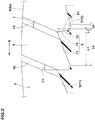
Fig. 2 is a cross-sectional view taken along A-A line ofFig. 1 . -
Fig. 3 is a cross-sectional view taken along B-B line ofFig. 1 . -
Fig. 4 is a perspective cross-sectional view of one of longitudinal grooves ofFig. 1 . -
Fig. 5 is a perspective cross-sectional view of one of the longitudinal grooves in another embodiment. -
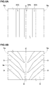
Fig. 6A is a development view of the tread portion in yet another embodiment. -
Fig. 6B is a development view of the tread portion in further another embodiment. - An embodiment of the present invention will now be described below in detail in conjunction with accompanying drawings.
-
Fig. 1 is a development view of atread portion 2 of a tyre 1 showing an embodiment of the present invention. In this embodiment, a pneumatic tyre for a passenger car is shown as a preferred example. However, it is needless to say that the present invention is applicable to the tyre 1 of other categories including a tyre for motorcycle or for heavy load, and a non-pneumatic tyre, for example. - The
tread portion 2 in this embodiment is bound with an intended tyre rotational direction (R). The tyre rotational direction (R) is indicated by letters and the like on a sidewall portion (not shown), for example. Note that the present invention is not limited to a tyre bound with the intended tyre rotational direction (R). - As shown in
Fig. 1 , thetread portion 2 is provided with at least onelongitudinal groove 3 extending in the tyre circumferential direction. Thetread portion 2 in this embodiment is provided with a plurality of thelongitudinal grooves 3. Thelongitudinal grooves 3 in this embodiment extends continuously in the tyre circumferential direction. Thelongitudinal grooves 3 includes a pair of crownlongitudinal grooves 4 each extending continuously in the tyre circumferential direction on a respective side of a tyre equator (C), and a pair of shoulderlongitudinal grooves 5 each extending continuously in the tyre circumferential direction on an outer side in a tyre axial direction of a respective one of the crownlongitudinal grooves 4. - The
tread portion 2 includesland regions 6 divided by thelongitudinal grooves 3. Theland regions 6 in this embodiment include acrown land region 6A, a pair ofmiddle land regions 6B, and a pair ofshoulder land regions 6C. Thecrown land region 6A is defined between the pair of the crownlongitudinal grooves 4. Each of themiddle land regions 6B in this embodiment is defined between a respective one of the crownlongitudinal grooves 4 and its adjacent one of the shoulderlongitudinal grooves 5. Each of theshoulder land regions 6C is defined between a respective one of the shoulderlongitudinal grooves 5 and its adjacent one of tread edges (Te). Note that thetread portion 2 of the tyre 1 of the present invention is not limited to such an embodiment. - The "tread edges" (Te) are defined as outermost ground contacting positions in a tyre axial direction when the tyre 1 in a standard state is in contact with a flat surface with zero camber angle by being loaded with a standard tyre load. The standard state is a state in which the tyre is mounted on a standard rim, inflated to a standard inner pressure, and loaded with no tyre load. In the standard state, a distance in the tyre axial direction between the tread edges (Te) is defined as a tread width TW. Dimensions and the like of various parts of the tyre 1 are those measured under the standard state, unless otherwise noted.
- The "standard rim" is a wheel rim specified for the concerned tyre by a standard included in a standardization system on which the tyre is based, for example, the "normal wheel rim" in JATMA, "Design Rim" in TRA, and "Measuring Rim" in ETRTO.
- The "standard inner pressure" is air pressure specified for the concerned tyre by a standard included in a standardization system on which the tyre is based, for example, the "maximum air pressure" in JATMA, maximum value listed in the "TIRE LOAD LIMITS AT VARIOUS COLD INFLATION PRESSURES" table in TRA, and "INFLATION PRESSURE" in ETRTO. when the tyre is for a passenger car, the standard inner pressure is 180 kPa.
- The "standard load" is a tyre load specified for the concerned tyre by a standard included in a standardization system on which the tyre 1 is based, for example, the "maximum load capacity" in JATMA, maximum value listed in "TIRE LOAD LIMITS AT VARIOUS COLD INFLATION PRESSURES" table in TRA, and "LOAD CAPACITY" in ETRTO. when the tyre is for a passenger car, the standard load is a load equivalent to 88% of the above load.
-
Fig. 2 is a cross-sectional view of one of thelongitudinal grooves 3 taken along A-A line ofFig. 1 .Fig. 3 is a cross-sectional view taken along B-B line ofFig. 1 .Fig. 4 is a perspective cross-sectional view of one of thelongitudinal grooves 3. As shown inFigs. 2 to 4 , the each of thelongitudinal grooves 3 in this embodiment has agroove bottom surface 7 and a pair ofgroove wall surfaces 8 extending outwardly in a tyre radial direction from thegroove bottom surface 7. - The
groove bottom surface 7 in this embodiment is provided with groovebottom protruding portions 9 each protruding outwardly in the tyre radial direction. The groovebottom protruding portions 9 change a groove cross-sectional area of each of thelongitudinal grooves 3 in the tyre circumferential direction. Thereby, frequency of the air column resonance sound generated when the tyre contacts the ground as it rotates changes, therefore, the constant frequency is not maintained, thus, the noise performance is improved. Each of the groove wall surfaces 8 in this embodiment is provided with groovewall protruding portions 10 each protruding toward a side of a groove center of a respective one of thelongitudinal grooves 3. The groovewall protruding portions 10 disturb a flow of air in each of thelongitudinal grooves 3, therefore, the air column resonance sound is decreased. Thereby, in the tyre 1 of the present invention, the noise performance is improved. - Each of the groove
bottom protruding portions 9 in this embodiment includes a firstinclined surface 11 inclined so that a groove depth decreases toward one side in the tyre circumferential direction and a secondinclined surface 12 connected with the firstinclined surface 11 and inclined so that the groove depth increases toward the one side in the tyre circumferential direction. The groovebottom protruding portions 9 configured as such effectively change the groove cross-sectional areas of thelongitudinal grooves 3, therefore, the noise performance is further improved. Further, the groovebottom protruding portions 9 configured as such ensure a smooth flow of water in thelongitudinal grooves 3, therefore, drainage performance is maintained. - Each of the groove
bottom protruding portions 9 in this embodiment is formed to have a triangular shape including atop portion 13 convex in the tyre radial direction at a intersection position between the firstinclined surface 11 and the secondinclined surface 12 in a cross-sectional view taken along a longitudinal direction of a respective one of thelongitudinal grooves 3. Each of the groovebottom protruding portions 9 configured as such effectively changes the groove cross-sectional area over the firstinclined surface 11 and the secondinclined surface 12. Thereby, the noise performance is further improved. Further, it is possible that the groovebottom protruding portions 9 configured as such flow the water more smoothly in thelongitudinal grooves 3, therefore, the drainage performance is maintained high. Furthermore, the groovebottom protruding portions 9 each formed in a triangular shape have smaller volume as compared with the groove bottom protruding portions each formed in a rectangular shape (not shown), therefore, heat generation due to hysteresis loss in the groovebottom protruding portions 9 is suppressed. - The "triangular shape" described above is not limited to a triangle formed by the first
inclined surface 11 and the secondinclined surface 12 configured as straight lines, but also includes an embodiment in which each of theinclined surfaces top portion 13 is formed by a circular arc having a small radius of curvature, for example. - Each of the first
inclined surface 11 and the secondinclined surface 12 extends straight and inwardly in the tyre radial direction from thetop portion 13 in the cross-sectional view described above. Thereby, the groove cross-sectional area gradually changes over the firstinclined surface 11 and the secondinclined surface 12, therefore, the noise performance is further improved. Furthermore, resistance of the water flowing in the grooves is maintained small, therefore, the drainage performance is improved. The firstinclined surface 11 and the secondinclined surface 12 are not limited to such an embodiment, they may be each configured as a smooth circular arc convex outwardly in the tyre radial direction or a smooth circular arc convex inwardly in the tyre radial direction, for example. - The first
inclined surface 11 in this embodiment is formed to have a length L1 in the tyre circumferential direction larger than a length L2 in the tyre circumferential direction of the secondinclined surface 12. with the secondinclined surfaces 12 configured as such, the changes of the groove cross-sectional area in thelongitudinal grooves 3 are relatively large, therefore, the noise performance is further improved. Furthermore, each of the firstinclined surface 11 has a relatively large surface area, therefore, it effectively contacts with the air flowing in a respective one of thelongitudinal grooves 3. Thereby, heat of thegroove bottom surface 7 due to the hysteresis loss as the tyre 1 rotates is effectively removed from the firstinclined surfaces 11, therefore, heat dissipation performance is improved. - In order to effectively exert the above-described effects, it is preferred that the length L1 of each of the first
inclined surfaces 11 is in about the range of from 80% to 95% of a length (La) in the tyre circumferential direction of each of the groovebottom protruding portions 9. Note that it is preferred that the length (La) in the tyre circumferential direction of each of the groovebottom protruding portions 9 is in about the range of from 0.5 to 2 times a groove width W1 of each of thelongitudinal grooves 3 having the groovebottom protruding portions 9, for example. - Each of the first
inclined surfaces 11 in this embodiment has a groove depth decreasing toward a toe-side in the tyre rotational direction (R). Thereby, the air having passed through the firstinclined surfaces 11 is smoothly discharged from the inside of thelongitudinal grooves 3 to the outside in the tyre radial direction while effectively removing heat from the groovebottom protruding portions 9. Further, the firstinclined surfaces 11 discharge the water in thelongitudinal grooves 3 smoothly to the toe-side in the tyre rotational direction (R), therefore, the drainage performance is maintained high. Each of the secondinclined surfaces 12 in this embodiment has a groove depth increasing toward the toe-side in the tyre rotational direction (R). - It is preferred that a height (h1) in the tyre radial direction of each of the groove
bottom protruding portions 9 is not less than 0.5mm. The groovebottom protruding portions 9 configured as such ensure the change in the cross-sectional area of each of thelongitudinal grooves 3, therefore, the noise performance is improved. If the height (h1) is excessively large, the groove cross-sectional area of each of thelongitudinal grooves 3 becomes small, therefore, it is possible that the drainage performance is deteriorated. Thereby, the height (h1) of each of the groovebottom protruding portions 9 is preferably not more than 3.0 mm, more preferably not more than 1.5 mm. - A plurality of the groove
bottom protruding portions 9 in this embodiment is provided along the longitudinal direction of each of thelongitudinal grooves 3. Thereby, the above-described effects are exerted on the circumference of the tyre, therefore, the noise performance, the heat dissipation performance, and the drainage performance are improved. - It is preferred that a length (Lb) in the longitudinal direction between the groove
bottom protruding portions 9 is not more than 15 mm. If the length (Lb) is larger than 15 mm, it is possible that the above-described effects by the groovebottom protruding portions 9 are deteriorated. Thereby, the length (Lb) is more preferably not more than 10 mm, further preferably not more than 5 mm. In this embodiment, amaximum depth portion 15 having the maximum depth is formed with a small length between each pair of the groovebottom protruding portions 9 adjacent to each other. Note that in the tyre 1 in this embodiment, the groovebottom protruding portions 9 may be formed continuously in the longitudinal direction without having themaximum depth portions 15. - The groove
wall protruding portions 10 in this embodiment are connected with the groovebottom protruding portions 9. The groovewall protruding portions 10 configured as such effectively disturb the flow of the air in thelongitudinal grooves 3 flowing along the groovebottom protruding portions 9, therefore, the air column resonance sound is further decreased. Further, the groovewall protruding portions 10 generate turbulent in thelongitudinal grooves 3, therefore, it is possible that the heat dissipation effect is increased. - Each of the groove
wall protruding portions 10 in this embodiment is connected with thetop portion 13 of a respective one of the groovebottom protruding portions 9. Each of the groovewall protruding portions 10 configured as such is formed to have a small height in the tyre radial direction, therefore, the resistance of water flow in thelongitudinal grooves 3 is maintained low, thereby, the drainage performance is improved. Each of the groovewall protruding portions 10 in this embodiment is connected on a respective one of the firstinclined surfaces 11 including thetop portion 13. - The groove
wall protruding portions 10 are each formed in a rib shape extending in the tyre radial direction. The groovewall protruding portions 10 configured as such exert the disturbing effect of the air flow while decreasing the resistance of the water flow in thelongitudinal grooves 3, therefore, the noise performance and the drainage performance are improved in a good balance. - Each of the groove
wall protruding portions 10 is formed in a rectangular shape in a cross section taken along the longitudinal direction of a respective one of thelongitudinal grooves 3. The groovewall protruding portions 10 configured as such effectively disturb the air flow in thelongitudinal grooves 3, therefore, the air column resonance sound is decreased. - A protruding length (d) of each of the groove
wall protruding portions 10 is in the range of from 0.5 to 5 mm. If the protruding length (d) of each of the groovewall protruding portions 10 is less than 0.5 mm, the disturbing effect of the air flow becomes small, therefore, it is possible that the noise performance is decreased. If the protruding length (d) of each of the groovewall protruding portions 10 is more than 5 mm, drainage resistance becomes large, therefore, it is possible that the drainage performance is deteriorated. - From the similar point of view, a length (t) in the tyre circumferential direction of each of the groove
wall protruding portions 10 is in the range of from 0.5 to 5 mm. - The groove
wall protruding portion 10 in this embodiment is provided on both of a pair of the groove wall surfaces 8 of a respective one of thelongitudinal grooves 3. Thereby, the above-described effects are effectively exerted. Each of the protrudingportions 10 in this embodiment provided on one of the pair of the groove wall surfaces 8 is formed at the same position with respect to the tyre circumferential direction as the corresponding one of the protrudingportions 10 provided on the other one of the pair of the groove wall surfaces 8. - Each of the groove
wall protruding portions 10 in this embodiment extends to a ground contacting surface (6a) of a respective one of theland regions 6. The groovewall protruding portions 10 configured as such effectively disturb the air flow in thelongitudinal grooves 3, therefore, the noise performance is improved. Further, it is possible that the groovewall protruding portions 10 smoothly guide the air and the water in thelongitudinal grooves 3 to the outside in the tyre radial direction. Thereby, the heat dissipation performance and the drainage performance are improved in a good balance. Each of the groovewall protruding portions 10 in this embodiment is formed so as to connect between a respective one of the groovebottom protruding portions 9 and the ground contacting surface (6a). - Each of the groove
wall protruding portions 10 in this embodiment is inclined toward the toe-side in the tyre rotational direction (R) as it goes radially outwardly. Thereby, the water and the air flowing along the firstinclined surfaces 11 as the tyre 1 rotates are discharged further smoothly to the outside in the tyre radial direction (the outside in the tyre radial direction of the ground contacting surfaces (6a) of the land regions 6). - It is preferred that an angle θ1 of each of the groove
wall protruding portions 10 with respect to the tyre radial direction is in the range of from 40 to 90 degrees at an inner end thereof in the tyre radial direction. If the angle θ1 of each of the groovewall protruding portions 10 is less than 40 degrees, the resistance of the water flowing in thelongitudinal grooves 3 is increased, therefore, it is possible that the drainage performance is deteriorated. Further, if the angle θ1 of each of the groovewall protruding portions 10 is more than 90 degrees, it is possible that the air and the water in thelongitudinal grooves 3 cannot be discharged to the outside in the tyre radial direction. From such a point of view, the angle θ1 of each of the groovewall protruding portions 10 is preferably not more than 80 degrees, more preferably not more than 70 degrees. - Each of the crown
longitudinal grooves 4 and the shoulderlongitudinal grooves 5 in this embodiment is provided with the groovebottom protruding portions 9 and the groovewall protruding portions 10 configured as such. Thereby, the above-described effects are exerted further effectively. - It is preferred that each of the
longitudinal grooves 3 provided with the groovebottom protruding portions 9 and the groovewall protruding portions 10 configured as such has the groove width W1 in about the range of from 5 to 15 mm and a groove depth D1 in about the range of from 6 to 15 mm. - The
crown land region 6A in this embodiment is provided withcrown lateral grooves 21 each extending from one of the crownlongitudinal grooves 4 toward the tyre equator (C) and a longitudinalshallow groove 22 extending continuously in the tyre circumferential direction. Each of themiddle land regions 6B in this embodiment is provided with middlelateral grooves 23 each extending in the tyre axial direction so as to connect between one of the crownlongitudinal grooves 4 and its adjacent one of the shoulderlongitudinal grooves 5, first middlelateral grooves 24 each extending from one of the crownlongitudinal grooves 4, and second middlelateral grooves 25 each extending from one of the shoulderlongitudinal grooves 5. Each of theshoulder land regions 6C in this embodiment is provided with shoulderlateral grooves 26 each extending in the tyre axial direction so as to connect between one of the shoulderlongitudinal grooves 5 and its adjacent one of the tread edges (Te), and shoulderlateral grooves 27 extending axially inwardly from one of the tread edges (Te) and terminating within theshoulder land regions 6C. A groove width w2 of each of the longitudinalshallow groove 22, each of thelateral grooves lateral grooves longitudinal grooves 3. Each of the longitudinalshallow groove 22, thelateral grooves -
Fig. 5 is a perspective cross-sectional view of one of thelongitudinal grooves 3 in another embodiment of the present invention. The same reference numerals are given to the elements common to the embodiment described above, and the explanation thereof is omitted here. Each of the crownlongitudinal grooves 4 and the shoulderlongitudinal grooves 5 in this embodiment is provided with the groovebottom protruding portions 9 and the groovewall protruding portions 10. - In this embodiment, the inclination direction of the first
inclined surfaces 11 of the groovebottom protruding portions 9 provided in each of the crownlongitudinal grooves 4 is opposite to the inclination direction of the firstinclined surfaces 11 of the groovebottom protruding portions 9 provided in each of the shoulderlongitudinal grooves 5. That is, each of the firstinclined surfaces 11 of the crownlongitudinal grooves 4 has the groove depth decreasing toward one side (the right side in the figure) in the tyre circumferential direction, and each of the firstinclined surfaces 11 of the shoulderlongitudinal grooves 5 has the groove depth decreasing toward the other side (the left side in the figure) in the tyre circumferential direction. Further in this embodiment, the inclination direction of the groovewall protruding portions 10 provided in the crownlongitudinal grooves 4 is opposite to the inclination direction of the groovewall protruding portions 10 provided in the shoulderlongitudinal grooves 5. That is, the groovewall protruding portions 10 of the crownlongitudinal grooves 4 are inclined toward one side in the tyre circumferential direction as it goes radially outwardly, and the groovewall protruding portions 10 of the shoulderlongitudinal grooves 5 are inclined toward the other side in the tyre circumferential direction as it goes radially outwardly. - As yet another embodiment of the present invention, in any pair of the
longitudinal grooves 3 adjacent to each other in the tyre axial direction, the inclination direction of the the firstinclined surfaces 11 of the groovebottom protruding portions 9 may be opposite to each other and the inclination direction of the groovewall protruding portions 10 may be opposite to each other. In this embodiment, the firstinclined surfaces 11 of one of the shoulderlongitudinal grooves 5 on one side in the tyre axial direction and one of the crownlongitudinal grooves 4 on the other side in the tyre axial direction are each inclined so that the groove depth thereof increases toward one side in the tyre circumferential direction. The firstinclined surfaces 11 of the groovebottom protruding portions 9 of one of the shoulderlongitudinal grooves 5 on the other side in the tyre axial direction and one of the crownlongitudinal grooves 4 on the one side in the tyre axial direction are each inclined so that the groove depth thereof increases toward the other side in the tyre circumferential direction. Further, the groovewall protruding portions 10 of one of the shoulderlongitudinal grooves 5 on the one side in the tyre axial direction and one of the crownlongitudinal grooves 4 on the other side in the tyre axial direction are each inclined toward the one side in the tyre circumferential direction as it goes radially outwardly. Conversely, the groovewall protruding portions 10 of one of the shoulderlongitudinal grooves 5 on the other side in the tyre axial direction and one of the crownlongitudinal grooves 4 on the one side in the tyre axial direction are each inclined toward the other side in the tyre circumferential direction as it goes radially outwardly (not shown). - Furthermore,
Fig. 6A shows further another embodiment of the present invention. The same reference numerals are given to the elements common to the embodiments described above, and the explanation thereof is omitted here. Thetread portion 2 in this embodiment is formed to have thelongitudinal grooves 3 composed of one crownlongitudinal groove 4 extending continuously in the tyre circumferential direction and a pair of the shoulderlongitudinal grooves 5 arranged on both sides of the crownlongitudinal groove 4 and each extending continuously in the tyre circumferential direction. Each of thelongitudinal grooves 3 is provided with the groovebottom protruding portions 9 and the groovewall protruding portions 10 of this embodiment (not shown). - Furthermore,
Fig. 6B shows further another embodiment. The same reference numerals are given to the elements common to the embodiments described above, and the explanation thereof is omitted here. Thetread portion 2 in this embodiment is provided with a plurality oflongitudinal grooves 3 arranged at intervals in the tyre circumferential direction on both sides of the tyre equator (C). Each of thelongitudinal grooves 3 in this embodiment has one end (3i) arranged spaced away from the tyre equator (C) and the other end (3e) connected with its adjacent one of the tread edges (Te), and is inclined with respect to the tyre circumferential direction. Theselongitudinal grooves 3 are provided with the groovebottom protruding portions 9 and the groovewall protruding portions 10 of this embodiment. - while detailed description has been made of the tyre as an embodiment of the present invention, it is needless to say that the present invention can be embodied in various forms without being limited to the illustrated embodiments.
- Tyres of size 255/50R20 having the basic pattern shown in
Fig. 1 were made by way of test according to the specifications listed in Table 1, and then each of the test tyres was tested for the noise performance, the heat dissipation performance, and the drainage performance. - Common specifications of the test tyres and the test methods were as follows.
Groove depth d1 of Longitudinal groove: 8 mm
Groove width W1 of Longitudinal groove: 11 mm
Length (La) of Groove bottom protruding portion/ Groove width W1 of Longitudinal groove (La/W1): 1 - Each of the test tyres was mounted on all wheels of an ordinary passenger car, and while the test car was driven on a road noise measuring road (a road having a rough asphalt surface) at a speed of 60 km/h, the in-car noise was sampled at a position in the vicinity of the driver's window-side ear, and the sound pressure level of the air-column resonance sound at a peak occurring around 240 Hz in the narrow band was measured. The results are indicated by an index based on the reciprocal of the sound pressure level of a Conventional example being 100, wherein the larger numerical value is better.
Tyre inner pressure: 200 kPa - A maximum temperature of the tread portion was measured while the above test car was driven on a dry asphalt road surface of a circuit test course. The results are indicated by an index based on the reciprocal of the maximum temperature of the Conventional example being 100, wherein the larger the numerical value, the lower the maximum temperature is, which shows better heat dissipation performance.
Driving speed: 80 km/h
Driving time: 30 minutes - By using an inside drum testing machine, while the test tyres were run on the drum surface covered by 5.0 mm depth of water under the following conditions, the speed when the hydroplaning phenomenon occurred was measured.
The results are indicated by an index based on the Conventional example being 100, wherein the larger the numerical value, the higher the speed when the hydroplaning phenomenon occurred is, which shows better drainage performance.
Slip angle: 1.0 degree
vertical load: 4.2 kN - The test results and the like are shown in Table 1.
Table 1. Conventional Example Example Reference Height (h1) of Groove bottom protruding portion [mm] - 1.5 1.5 Length (La) of Groove bottom protruding portion [mm] - 11 11 Length (Lb) of Groove bottom protruding portion [mm] - 0.1 0.1 Ratio (L1/La) of Length (L1) of First inclined surface and - 90 50 Length (La) of Groove bottom protruding portion [%] Angle (θ1) of Groove wall protruding portion [degree] - 40 - Protruding length (d) of Groove wall protruding portion [mm] - 2.0 - Noise performance [index: larger is better] 100 130 103 Heat dissipation performance [index: larger is better] 100 130 105 Drainage performance [index: larger is better] 100 130 100 - From the test results, it was confirmed that the noise performance was improved for the tyres as Example as compared with the tyres as Reference. Further, it was confirmed that the heat dissipation performance and the drainage performance were improved as well for the tyres as the Example as compared with the tyres as the Reference.
Claims (8)
- A tyre (1) comprising a tread portion (2) comprising at least one longitudinal groove (3) extending in a tyre circumferential direction, wherein
the longitudinal groove (3) has a groove bottom surface (7) and a pair of groove wall surfaces (8) extending outwardly in a tyre radial direction from the groove bottom surface,
the groove bottom surface (7) is provided with a groove bottom protruding portion (9) protruding outwardly in the tyre radial direction, and
at least one of the pair of the groove wall surfaces (8) is provided with a groove wall protruding portion (10) protruding toward a side of a groove center of the longitudinal groove (3), wherein
the groove wall protruding portion (10) extends to a ground contacting surface of a land region of the tread portion (2) and the groove wall protruding portion (10) is formed in a rib shape extending in the tyre radial direction and is formed in a rectangular shape in a cross section taken along the longitudinal direction of a respective one of the longitudinal grooves (3),
wherein a protruding length (d) of each of the groove wall protruding portions (10) is in the range of from 0.5 to 5 mm, and
wherein a length (t) in the tyre circumferential direction of each of the groove wall protruding portions (10) is in the range of from 0.5 to 5 mm,
wherein the or each groove bottom protruding portion (9) includes a first inclined surface (11) inclined so that a groove depth decreases toward one side in the tyre circumferential direction and a second inclined surface (12) connected with the first inclined surface and inclined so that the groove depth increases toward the one side in the tyre circumferential direction. - The tyre (1) according to claim 1, wherein
the groove wall protruding portion (10) is connected with the groove bottom protruding portion (9). - The tyre (1) according to claim 1 or 2, wherein
a height in the tyre radial direction of the groove bottom protruding portion (9) is not less than 0.5 mm. - The tyre (1) according to any one of claims 1 to 3, wherein
a plurality of the groove bottom protruding portions (9) is arranged along a longitudinal direction of the longitudinal groove (3), and
a length in the longitudinal direction between the groove bottom protruding portions (9) adjacent to each other is not more than 15 mm. - The tyre (1) according to claim 1, wherein
a length in the tyre circumferential direction of the first inclined surface (11) is larger than a length in the tyre circumferential direction of the second inclined surface (12). - The tyre (1) according to claim 1 or 5, wherein
the tread portion (2) is bound with an intended tyre rotational direction, and
the first inclined surface (11) is inclined so that the groove depth decreases toward a toe-side in the tyre rotational direction. - The tyre (1) according to any one of claims 1 to 6, wherein
the tread portion (2) is bound with an intended tyre rotational direction, and
the groove wall protruding portion (10) is inclined toward a toe-side in the tyre rotational direction as it goes radially outwardly. - The tyre (1) according to any one of claims 1 to 7, wherein
in a standard state in which the tyre (1) is mounted on a standard rim, inflated to a standard inner pressure, and loaded with no tyre load, an angle of the groove wall protruding portion (10) with respect to the tyre radial direction is in a range of from 40 to 90 degrees at an inner end thereof in the tyre radial direction.
Applications Claiming Priority (1)
| Application Number | Priority Date | Filing Date | Title |
|---|---|---|---|
| JP2017244325A JP7027873B2 (en) | 2017-12-20 | 2017-12-20 | tire |
Publications (2)
| Publication Number | Publication Date |
|---|---|
| EP3501852A1 EP3501852A1 (en) | 2019-06-26 |
| EP3501852B1 true EP3501852B1 (en) | 2021-06-16 |
Family
ID=64277522
Family Applications (1)
| Application Number | Title | Priority Date | Filing Date |
|---|---|---|---|
| EP18205566.5A Active EP3501852B1 (en) | 2017-12-20 | 2018-11-12 | Tyre |
Country Status (3)
| Country | Link |
|---|---|
| US (1) | US11059328B2 (en) |
| EP (1) | EP3501852B1 (en) |
| JP (1) | JP7027873B2 (en) |
Families Citing this family (6)
| Publication number | Priority date | Publication date | Assignee | Title |
|---|---|---|---|---|
| JP7027907B2 (en) * | 2018-01-23 | 2022-03-02 | 住友ゴム工業株式会社 | tire |
| JP7310314B2 (en) * | 2019-05-31 | 2023-07-19 | 住友ゴム工業株式会社 | tire |
| KR102283846B1 (en) * | 2019-11-12 | 2021-08-03 | 한국타이어앤테크놀로지 주식회사 | Tires with noise-reducing main grooves |
| EP3854611B1 (en) * | 2020-01-23 | 2023-06-07 | Aeolus Tyre Co., Ltd. | Low-noise and high-wet-skidding-resistance tire |
| KR102445780B1 (en) * | 2021-01-06 | 2022-09-22 | 금호타이어 주식회사 | Pneumatic tire |
| JP2023006030A (en) | 2021-06-30 | 2023-01-18 | 住友ゴム工業株式会社 | pneumatic tire |
Family Cites Families (29)
| Publication number | Priority date | Publication date | Assignee | Title |
|---|---|---|---|---|
| JPH0386605A (en) * | 1989-08-30 | 1991-04-11 | Bridgestone Corp | Pneumatic tire having superior drainage performance |
| JP3103641B2 (en) * | 1991-12-24 | 2000-10-30 | 住友ゴム工業株式会社 | tire |
| JP2724122B2 (en) * | 1993-12-27 | 1998-03-09 | 廣壽 深田 | Vehicle tires |
| CN1054342C (en) * | 1993-12-27 | 2000-07-12 | 深田广寿 | Tire for vehicle |
| JP3410650B2 (en) * | 1998-01-27 | 2003-05-26 | 住友ゴム工業株式会社 | Pneumatic tire |
| US6415835B1 (en) * | 2000-06-08 | 2002-07-09 | The Goodyear Tire & Rubber Company | Pneumatic tire tread having groove with peaks and valleys |
| KR100462208B1 (en) * | 2000-06-30 | 2004-12-16 | 한국타이어 주식회사 | Pneumatic Vehicle Tire |
| ES2297017T3 (en) * | 2001-05-11 | 2008-05-01 | Bridgestone Corporation | TIRE. |
| JP4363527B2 (en) | 2002-11-26 | 2009-11-11 | 横浜ゴム株式会社 | Pneumatic tire |
| JP4316268B2 (en) | 2003-03-24 | 2009-08-19 | 横浜ゴム株式会社 | Pneumatic tire |
| US7004216B2 (en) * | 2003-12-11 | 2006-02-28 | The Goodyear Tire & Rubber Company | Tire tread including spaced projections in base of groove |
| JP2005231600A (en) * | 2004-02-23 | 2005-09-02 | Yokohama Rubber Co Ltd:The | Pneumatic tire and manufacturing mold thereof |
| JP4529680B2 (en) | 2004-12-27 | 2010-08-25 | 横浜ゴム株式会社 | Pneumatic tire |
| JP4723939B2 (en) * | 2005-07-22 | 2011-07-13 | 株式会社ブリヂストン | Pneumatic tire |
| JP5011880B2 (en) * | 2005-09-21 | 2012-08-29 | 横浜ゴム株式会社 | Pneumatic tire |
| JP5374362B2 (en) * | 2007-03-12 | 2013-12-25 | 株式会社ブリヂストン | Pneumatic tire |
| DE102009044123A1 (en) * | 2009-09-29 | 2011-03-31 | Continental Reifen Deutschland Gmbh | Tread pattern of a pneumatic vehicle tire |
| JP2012035684A (en) | 2010-08-05 | 2012-02-23 | Yokohama Rubber Co Ltd:The | Pneumatic tire |
| JP2013151240A (en) | 2012-01-25 | 2013-08-08 | Bridgestone Corp | Vehicle tire |
| JP5953064B2 (en) | 2012-02-21 | 2016-07-13 | 株式会社ブリヂストン | tire |
| JP5557875B2 (en) * | 2012-05-18 | 2014-07-23 | 株式会社ブリヂストン | Pneumatic tire |
| JP6012397B2 (en) * | 2012-10-24 | 2016-10-25 | 株式会社ブリヂストン | Pneumatic tire |
| JP6031400B2 (en) * | 2013-04-12 | 2016-11-24 | 株式会社ブリヂストン | Aircraft tire |
| JP6124667B2 (en) | 2013-04-25 | 2017-05-10 | 東洋ゴム工業株式会社 | Pneumatic tire |
| KR20160104056A (en) * | 2014-02-04 | 2016-09-02 | 브리지스톤 어메리카스 타이어 오퍼레이션스, 엘엘씨 | Radial stone ejectors |
| JP2016052812A (en) * | 2014-09-03 | 2016-04-14 | 横浜ゴム株式会社 | Pneumatic tire |
| JP6488838B2 (en) | 2015-04-07 | 2019-03-27 | 横浜ゴム株式会社 | Pneumatic tire |
| CN108430803B (en) | 2015-12-25 | 2020-06-16 | 米其林企业总公司 | Noise reducing tread |
| JP2019018798A (en) | 2017-07-20 | 2019-02-07 | 横浜ゴム株式会社 | Pneumatic tire |
-
2017
- 2017-12-20 JP JP2017244325A patent/JP7027873B2/en active Active
-
2018
- 2018-11-12 EP EP18205566.5A patent/EP3501852B1/en active Active
- 2018-12-04 US US16/209,565 patent/US11059328B2/en active Active
Non-Patent Citations (1)
| Title |
|---|
| None * |
Also Published As
| Publication number | Publication date |
|---|---|
| JP2019111838A (en) | 2019-07-11 |
| EP3501852A1 (en) | 2019-06-26 |
| JP7027873B2 (en) | 2022-03-02 |
| US11059328B2 (en) | 2021-07-13 |
| US20190184754A1 (en) | 2019-06-20 |
Similar Documents
| Publication | Publication Date | Title |
|---|---|---|
| US10239358B2 (en) | Pneumatic tire | |
| EP2789481B1 (en) | Tread band of a pneumatic tire | |
| EP3501852B1 (en) | Tyre | |
| EP3147139B1 (en) | Pneumatic tire | |
| EP3015286B1 (en) | Pneumatic tire | |
| US10618355B2 (en) | Pneumatic tire | |
| US10384491B2 (en) | Pneumatic tire | |
| EP2732983B1 (en) | Pneumatic tire | |
| US8210219B2 (en) | Pneumatic tire with tread having crown rib and middle ribs | |
| EP3095623B1 (en) | Pneumatic tire | |
| EP3093162B1 (en) | Pneumatic tire | |
| US9085201B2 (en) | Pneumatic tire | |
| US20170015143A1 (en) | Pneumatic tire | |
| US10399390B2 (en) | Pneumatic tire | |
| US11207922B2 (en) | Tire | |
| US10981418B2 (en) | Tire | |
| US20150273948A1 (en) | Pneumatic tire | |
| US11325426B2 (en) | Tire | |
| US11135877B2 (en) | Tire | |
| US11780270B2 (en) | Tire | |
| CN110588250A (en) | Tyre for vehicle wheels |
Legal Events
| Date | Code | Title | Description |
|---|---|---|---|
| PUAI | Public reference made under article 153(3) epc to a published international application that has entered the european phase |
Free format text: ORIGINAL CODE: 0009012 |
|
| STAA | Information on the status of an ep patent application or granted ep patent |
Free format text: STATUS: THE APPLICATION HAS BEEN PUBLISHED |
|
| AK | Designated contracting states |
Kind code of ref document: A1 Designated state(s): AL AT BE BG CH CY CZ DE DK EE ES FI FR GB GR HR HU IE IS IT LI LT LU LV MC MK MT NL NO PL PT RO RS SE SI SK SM TR |
|
| AX | Request for extension of the european patent |
Extension state: BA ME |
|
| STAA | Information on the status of an ep patent application or granted ep patent |
Free format text: STATUS: REQUEST FOR EXAMINATION WAS MADE |
|
| 17P | Request for examination filed |
Effective date: 20191209 |
|
| RBV | Designated contracting states (corrected) |
Designated state(s): AL AT BE BG CH CY CZ DE DK EE ES FI FR GB GR HR HU IE IS IT LI LT LU LV MC MK MT NL NO PL PT RO RS SE SI SK SM TR |
|
| STAA | Information on the status of an ep patent application or granted ep patent |
Free format text: STATUS: EXAMINATION IS IN PROGRESS |
|
| 17Q | First examination report despatched |
Effective date: 20200414 |
|
| STAA | Information on the status of an ep patent application or granted ep patent |
Free format text: STATUS: EXAMINATION IS IN PROGRESS |
|
| GRAP | Despatch of communication of intention to grant a patent |
Free format text: ORIGINAL CODE: EPIDOSNIGR1 |
|
| STAA | Information on the status of an ep patent application or granted ep patent |
Free format text: STATUS: GRANT OF PATENT IS INTENDED |
|
| RIC1 | Information provided on ipc code assigned before grant |
Ipc: B60C 11/04 20060101AFI20210118BHEP Ipc: B60C 19/00 20060101ALI20210118BHEP Ipc: B60C 11/13 20060101ALI20210118BHEP Ipc: B60C 11/03 20060101ALI20210118BHEP |
|
| INTG | Intention to grant announced |
Effective date: 20210218 |
|
| GRAS | Grant fee paid |
Free format text: ORIGINAL CODE: EPIDOSNIGR3 |
|
| GRAA | (expected) grant |
Free format text: ORIGINAL CODE: 0009210 |
|
| STAA | Information on the status of an ep patent application or granted ep patent |
Free format text: STATUS: THE PATENT HAS BEEN GRANTED |
|
| AK | Designated contracting states |
Kind code of ref document: B1 Designated state(s): AL AT BE BG CH CY CZ DE DK EE ES FI FR GB GR HR HU IE IS IT LI LT LU LV MC MK MT NL NO PL PT RO RS SE SI SK SM TR |
|
| REG | Reference to a national code |
Ref country code: GB Ref legal event code: FG4D |
|
| REG | Reference to a national code |
Ref country code: CH Ref legal event code: EP |
|
| REG | Reference to a national code |
Ref country code: DE Ref legal event code: R096 Ref document number: 602018018608 Country of ref document: DE |
|
| REG | Reference to a national code |
Ref country code: AT Ref legal event code: REF Ref document number: 1402026 Country of ref document: AT Kind code of ref document: T Effective date: 20210715 |
|
| REG | Reference to a national code |
Ref country code: IE Ref legal event code: FG4D |
|
| REG | Reference to a national code |
Ref country code: LT Ref legal event code: MG9D |
|
| PG25 | Lapsed in a contracting state [announced via postgrant information from national office to epo] |
Ref country code: BG Free format text: LAPSE BECAUSE OF FAILURE TO SUBMIT A TRANSLATION OF THE DESCRIPTION OR TO PAY THE FEE WITHIN THE PRESCRIBED TIME-LIMIT Effective date: 20210916 Ref country code: FI Free format text: LAPSE BECAUSE OF FAILURE TO SUBMIT A TRANSLATION OF THE DESCRIPTION OR TO PAY THE FEE WITHIN THE PRESCRIBED TIME-LIMIT Effective date: 20210616 Ref country code: LT Free format text: LAPSE BECAUSE OF FAILURE TO SUBMIT A TRANSLATION OF THE DESCRIPTION OR TO PAY THE FEE WITHIN THE PRESCRIBED TIME-LIMIT Effective date: 20210616 Ref country code: HR Free format text: LAPSE BECAUSE OF FAILURE TO SUBMIT A TRANSLATION OF THE DESCRIPTION OR TO PAY THE FEE WITHIN THE PRESCRIBED TIME-LIMIT Effective date: 20210616 |
|
| REG | Reference to a national code |
Ref country code: AT Ref legal event code: MK05 Ref document number: 1402026 Country of ref document: AT Kind code of ref document: T Effective date: 20210616 |
|
| REG | Reference to a national code |
Ref country code: NL Ref legal event code: MP Effective date: 20210616 |
|
| PG25 | Lapsed in a contracting state [announced via postgrant information from national office to epo] |
Ref country code: GR Free format text: LAPSE BECAUSE OF FAILURE TO SUBMIT A TRANSLATION OF THE DESCRIPTION OR TO PAY THE FEE WITHIN THE PRESCRIBED TIME-LIMIT Effective date: 20210917 Ref country code: NO Free format text: LAPSE BECAUSE OF FAILURE TO SUBMIT A TRANSLATION OF THE DESCRIPTION OR TO PAY THE FEE WITHIN THE PRESCRIBED TIME-LIMIT Effective date: 20210916 Ref country code: LV Free format text: LAPSE BECAUSE OF FAILURE TO SUBMIT A TRANSLATION OF THE DESCRIPTION OR TO PAY THE FEE WITHIN THE PRESCRIBED TIME-LIMIT Effective date: 20210616 Ref country code: SE Free format text: LAPSE BECAUSE OF FAILURE TO SUBMIT A TRANSLATION OF THE DESCRIPTION OR TO PAY THE FEE WITHIN THE PRESCRIBED TIME-LIMIT Effective date: 20210616 Ref country code: RS Free format text: LAPSE BECAUSE OF FAILURE TO SUBMIT A TRANSLATION OF THE DESCRIPTION OR TO PAY THE FEE WITHIN THE PRESCRIBED TIME-LIMIT Effective date: 20210616 |
|
| PG25 | Lapsed in a contracting state [announced via postgrant information from national office to epo] |
Ref country code: EE Free format text: LAPSE BECAUSE OF FAILURE TO SUBMIT A TRANSLATION OF THE DESCRIPTION OR TO PAY THE FEE WITHIN THE PRESCRIBED TIME-LIMIT Effective date: 20210616 Ref country code: ES Free format text: LAPSE BECAUSE OF FAILURE TO SUBMIT A TRANSLATION OF THE DESCRIPTION OR TO PAY THE FEE WITHIN THE PRESCRIBED TIME-LIMIT Effective date: 20210616 Ref country code: SK Free format text: LAPSE BECAUSE OF FAILURE TO SUBMIT A TRANSLATION OF THE DESCRIPTION OR TO PAY THE FEE WITHIN THE PRESCRIBED TIME-LIMIT Effective date: 20210616 Ref country code: SM Free format text: LAPSE BECAUSE OF FAILURE TO SUBMIT A TRANSLATION OF THE DESCRIPTION OR TO PAY THE FEE WITHIN THE PRESCRIBED TIME-LIMIT Effective date: 20210616 Ref country code: PT Free format text: LAPSE BECAUSE OF FAILURE TO SUBMIT A TRANSLATION OF THE DESCRIPTION OR TO PAY THE FEE WITHIN THE PRESCRIBED TIME-LIMIT Effective date: 20211018 Ref country code: NL Free format text: LAPSE BECAUSE OF FAILURE TO SUBMIT A TRANSLATION OF THE DESCRIPTION OR TO PAY THE FEE WITHIN THE PRESCRIBED TIME-LIMIT Effective date: 20210616 Ref country code: RO Free format text: LAPSE BECAUSE OF FAILURE TO SUBMIT A TRANSLATION OF THE DESCRIPTION OR TO PAY THE FEE WITHIN THE PRESCRIBED TIME-LIMIT Effective date: 20210616 Ref country code: AT Free format text: LAPSE BECAUSE OF FAILURE TO SUBMIT A TRANSLATION OF THE DESCRIPTION OR TO PAY THE FEE WITHIN THE PRESCRIBED TIME-LIMIT Effective date: 20210616 Ref country code: CZ Free format text: LAPSE BECAUSE OF FAILURE TO SUBMIT A TRANSLATION OF THE DESCRIPTION OR TO PAY THE FEE WITHIN THE PRESCRIBED TIME-LIMIT Effective date: 20210616 |
|
| PG25 | Lapsed in a contracting state [announced via postgrant information from national office to epo] |
Ref country code: PL Free format text: LAPSE BECAUSE OF FAILURE TO SUBMIT A TRANSLATION OF THE DESCRIPTION OR TO PAY THE FEE WITHIN THE PRESCRIBED TIME-LIMIT Effective date: 20210616 |
|
| REG | Reference to a national code |
Ref country code: DE Ref legal event code: R097 Ref document number: 602018018608 Country of ref document: DE |
|
| PLBE | No opposition filed within time limit |
Free format text: ORIGINAL CODE: 0009261 |
|
| STAA | Information on the status of an ep patent application or granted ep patent |
Free format text: STATUS: NO OPPOSITION FILED WITHIN TIME LIMIT |
|
| PG25 | Lapsed in a contracting state [announced via postgrant information from national office to epo] |
Ref country code: DK Free format text: LAPSE BECAUSE OF FAILURE TO SUBMIT A TRANSLATION OF THE DESCRIPTION OR TO PAY THE FEE WITHIN THE PRESCRIBED TIME-LIMIT Effective date: 20210616 |
|
| 26N | No opposition filed |
Effective date: 20220317 |
|
| PG25 | Lapsed in a contracting state [announced via postgrant information from national office to epo] |
Ref country code: AL Free format text: LAPSE BECAUSE OF FAILURE TO SUBMIT A TRANSLATION OF THE DESCRIPTION OR TO PAY THE FEE WITHIN THE PRESCRIBED TIME-LIMIT Effective date: 20210616 |
|
| PG25 | Lapsed in a contracting state [announced via postgrant information from national office to epo] |
Ref country code: MC Free format text: LAPSE BECAUSE OF FAILURE TO SUBMIT A TRANSLATION OF THE DESCRIPTION OR TO PAY THE FEE WITHIN THE PRESCRIBED TIME-LIMIT Effective date: 20210616 |
|
| REG | Reference to a national code |
Ref country code: CH Ref legal event code: PL |
|
| PG25 | Lapsed in a contracting state [announced via postgrant information from national office to epo] |
Ref country code: LU Free format text: LAPSE BECAUSE OF NON-PAYMENT OF DUE FEES Effective date: 20211112 Ref country code: IT Free format text: LAPSE BECAUSE OF FAILURE TO SUBMIT A TRANSLATION OF THE DESCRIPTION OR TO PAY THE FEE WITHIN THE PRESCRIBED TIME-LIMIT Effective date: 20210616 Ref country code: BE Free format text: LAPSE BECAUSE OF NON-PAYMENT OF DUE FEES Effective date: 20211130 |
|
| REG | Reference to a national code |
Ref country code: BE Ref legal event code: MM Effective date: 20211130 |
|
| PG25 | Lapsed in a contracting state [announced via postgrant information from national office to epo] |
Ref country code: LI Free format text: LAPSE BECAUSE OF NON-PAYMENT OF DUE FEES Effective date: 20211130 Ref country code: CH Free format text: LAPSE BECAUSE OF NON-PAYMENT OF DUE FEES Effective date: 20211130 |
|
| PG25 | Lapsed in a contracting state [announced via postgrant information from national office to epo] |
Ref country code: IE Free format text: LAPSE BECAUSE OF NON-PAYMENT OF DUE FEES Effective date: 20211112 |
|
| P01 | Opt-out of the competence of the unified patent court (upc) registered |
Effective date: 20230510 |
|
| PG25 | Lapsed in a contracting state [announced via postgrant information from national office to epo] |
Ref country code: CY Free format text: LAPSE BECAUSE OF FAILURE TO SUBMIT A TRANSLATION OF THE DESCRIPTION OR TO PAY THE FEE WITHIN THE PRESCRIBED TIME-LIMIT Effective date: 20210616 |
|
| GBPC | Gb: european patent ceased through non-payment of renewal fee |
Effective date: 20221112 |
|
| PG25 | Lapsed in a contracting state [announced via postgrant information from national office to epo] |
Ref country code: HU Free format text: LAPSE BECAUSE OF FAILURE TO SUBMIT A TRANSLATION OF THE DESCRIPTION OR TO PAY THE FEE WITHIN THE PRESCRIBED TIME-LIMIT; INVALID AB INITIO Effective date: 20181112 |
|
| PG25 | Lapsed in a contracting state [announced via postgrant information from national office to epo] |
Ref country code: GB Free format text: LAPSE BECAUSE OF NON-PAYMENT OF DUE FEES Effective date: 20221112 |
|
| PGFP | Annual fee paid to national office [announced via postgrant information from national office to epo] |
Ref country code: FR Payment date: 20230929 Year of fee payment: 6 |
|
| PGFP | Annual fee paid to national office [announced via postgrant information from national office to epo] |
Ref country code: DE Payment date: 20230929 Year of fee payment: 6 |