EP2537347B1 - Vorrichtung und verfahren zur bearbeitung von videoinhalten - Google Patents
Vorrichtung und verfahren zur bearbeitung von videoinhalten Download PDFInfo
- Publication number
- EP2537347B1 EP2537347B1 EP11706395.8A EP11706395A EP2537347B1 EP 2537347 B1 EP2537347 B1 EP 2537347B1 EP 11706395 A EP11706395 A EP 11706395A EP 2537347 B1 EP2537347 B1 EP 2537347B1
- Authority
- EP
- European Patent Office
- Prior art keywords
- image
- video
- signal
- resolution
- video signal
- Prior art date
- Legal status (The legal status is an assumption and is not a legal conclusion. Google has not performed a legal analysis and makes no representation as to the accuracy of the status listed.)
- Active
Links
Images


Classifications
-
- H—ELECTRICITY
- H04—ELECTRIC COMMUNICATION TECHNIQUE
- H04N—PICTORIAL COMMUNICATION, e.g. TELEVISION
- H04N13/00—Stereoscopic video systems; Multi-view video systems; Details thereof
- H04N13/10—Processing, recording or transmission of stereoscopic or multi-view image signals
- H04N13/106—Processing image signals
- H04N13/139—Format conversion, e.g. of frame-rate or size
-
- H—ELECTRICITY
- H04—ELECTRIC COMMUNICATION TECHNIQUE
- H04N—PICTORIAL COMMUNICATION, e.g. TELEVISION
- H04N13/00—Stereoscopic video systems; Multi-view video systems; Details thereof
- H04N13/10—Processing, recording or transmission of stereoscopic or multi-view image signals
- H04N13/106—Processing image signals
- H04N13/156—Mixing image signals
-
- H—ELECTRICITY
- H04—ELECTRIC COMMUNICATION TECHNIQUE
- H04N—PICTORIAL COMMUNICATION, e.g. TELEVISION
- H04N13/00—Stereoscopic video systems; Multi-view video systems; Details thereof
- H04N13/10—Processing, recording or transmission of stereoscopic or multi-view image signals
- H04N13/106—Processing image signals
- H04N13/161—Encoding, multiplexing or demultiplexing different image signal components
-
- H—ELECTRICITY
- H04—ELECTRIC COMMUNICATION TECHNIQUE
- H04N—PICTORIAL COMMUNICATION, e.g. TELEVISION
- H04N13/00—Stereoscopic video systems; Multi-view video systems; Details thereof
- H04N13/10—Processing, recording or transmission of stereoscopic or multi-view image signals
- H04N13/106—Processing image signals
- H04N13/167—Synchronising or controlling image signals
-
- H—ELECTRICITY
- H04—ELECTRIC COMMUNICATION TECHNIQUE
- H04N—PICTORIAL COMMUNICATION, e.g. TELEVISION
- H04N13/00—Stereoscopic video systems; Multi-view video systems; Details thereof
- H04N13/10—Processing, recording or transmission of stereoscopic or multi-view image signals
- H04N13/194—Transmission of image signals
-
- H—ELECTRICITY
- H04—ELECTRIC COMMUNICATION TECHNIQUE
- H04N—PICTORIAL COMMUNICATION, e.g. TELEVISION
- H04N13/00—Stereoscopic video systems; Multi-view video systems; Details thereof
- H04N13/30—Image reproducers
- H04N13/356—Image reproducers having separate monoscopic and stereoscopic modes
- H04N13/359—Switching between monoscopic and stereoscopic modes
-
- H—ELECTRICITY
- H04—ELECTRIC COMMUNICATION TECHNIQUE
- H04N—PICTORIAL COMMUNICATION, e.g. TELEVISION
- H04N13/00—Stereoscopic video systems; Multi-view video systems; Details thereof
- H04N13/30—Image reproducers
- H04N13/398—Synchronisation thereof; Control thereof
-
- H—ELECTRICITY
- H04—ELECTRIC COMMUNICATION TECHNIQUE
- H04N—PICTORIAL COMMUNICATION, e.g. TELEVISION
- H04N19/00—Methods or arrangements for coding, decoding, compressing or decompressing digital video signals
- H04N19/50—Methods or arrangements for coding, decoding, compressing or decompressing digital video signals using predictive coding
- H04N19/597—Methods or arrangements for coding, decoding, compressing or decompressing digital video signals using predictive coding specially adapted for multi-view video sequence encoding
-
- H—ELECTRICITY
- H04—ELECTRIC COMMUNICATION TECHNIQUE
- H04N—PICTORIAL COMMUNICATION, e.g. TELEVISION
- H04N21/00—Selective content distribution, e.g. interactive television or video on demand [VOD]
- H04N21/40—Client devices specifically adapted for the reception of or interaction with content, e.g. set-top-box [STB]; Operations thereof
- H04N21/43—Processing of content or additional data, e.g. demultiplexing additional data from a digital video stream; Elementary client operations, e.g. monitoring of home network or synchronising decoder's clock; Client middleware
- H04N21/44—Processing of video elementary streams, e.g. splicing a video clip retrieved from local storage with an incoming video stream, rendering scenes according to MPEG-4 scene graphs
- H04N21/4402—Processing of video elementary streams, e.g. splicing a video clip retrieved from local storage with an incoming video stream, rendering scenes according to MPEG-4 scene graphs involving reformatting operations of video signals for household redistribution, storage or real-time display
- H04N21/440263—Processing of video elementary streams, e.g. splicing a video clip retrieved from local storage with an incoming video stream, rendering scenes according to MPEG-4 scene graphs involving reformatting operations of video signals for household redistribution, storage or real-time display by altering the spatial resolution, e.g. for displaying on a connected PDA
- H04N21/440272—Processing of video elementary streams, e.g. splicing a video clip retrieved from local storage with an incoming video stream, rendering scenes according to MPEG-4 scene graphs involving reformatting operations of video signals for household redistribution, storage or real-time display by altering the spatial resolution, e.g. for displaying on a connected PDA for performing aspect ratio conversion
-
- H—ELECTRICITY
- H04—ELECTRIC COMMUNICATION TECHNIQUE
- H04N—PICTORIAL COMMUNICATION, e.g. TELEVISION
- H04N21/00—Selective content distribution, e.g. interactive television or video on demand [VOD]
- H04N21/40—Client devices specifically adapted for the reception of or interaction with content, e.g. set-top-box [STB]; Operations thereof
- H04N21/43—Processing of content or additional data, e.g. demultiplexing additional data from a digital video stream; Elementary client operations, e.g. monitoring of home network or synchronising decoder's clock; Client middleware
- H04N21/44—Processing of video elementary streams, e.g. splicing a video clip retrieved from local storage with an incoming video stream, rendering scenes according to MPEG-4 scene graphs
- H04N21/4402—Processing of video elementary streams, e.g. splicing a video clip retrieved from local storage with an incoming video stream, rendering scenes according to MPEG-4 scene graphs involving reformatting operations of video signals for household redistribution, storage or real-time display
- H04N21/44029—Processing of video elementary streams, e.g. splicing a video clip retrieved from local storage with an incoming video stream, rendering scenes according to MPEG-4 scene graphs involving reformatting operations of video signals for household redistribution, storage or real-time display for generating different versions
-
- H—ELECTRICITY
- H04—ELECTRIC COMMUNICATION TECHNIQUE
- H04N—PICTORIAL COMMUNICATION, e.g. TELEVISION
- H04N21/00—Selective content distribution, e.g. interactive television or video on demand [VOD]
- H04N21/80—Generation or processing of content or additional data by content creator independently of the distribution process; Content per se
- H04N21/81—Monomedia components thereof
- H04N21/816—Monomedia components thereof involving special video data, e.g 3D video
-
- H—ELECTRICITY
- H04—ELECTRIC COMMUNICATION TECHNIQUE
- H04N—PICTORIAL COMMUNICATION, e.g. TELEVISION
- H04N2213/00—Details of stereoscopic systems
- H04N2213/007—Aspects relating to detection of stereoscopic image format, e.g. for adaptation to the display format
Definitions
- the present disclosure generally relates to digital content systems and methods for delivering content to an end user, and more particularly, to systems and low bandwidth methods to encode and broadcast a video multiplex that allows a receiver to select and decode any one of the following: half resolution split screen stereo video, full resolution two-dimensional (2D) video, full resolution stereo video.
- Home entertainment systems including television (TV) and media centers, are converging with the Internet and providing access to a large number of available sources of content, such as video, movies, TV programs, music, etc.
- content such as video, movies, TV programs, music, etc.
- challenges have emerged related to the display and navigating process for that accessible content.
- Broadcasters eager to test the three dimensional (3D) display to the home video market, want to adopt a broadcast format that is backward compatible with all existing high definition (HD) capable set-top boxes in the field.
- the broadcasters have recently chosen to begin 3D video broadcasts with a half horizontal resolution split-screen encoding of the left and right stereo video views. In this scenario, as well as other split-screen video scenarios, it is the display device that converts from the split-screen format to a format that can be perceived as stereo video by the viewer.
- the Blu-ray Disc Association has elected the multi-view compression algorithm, also known as Multiview Video Coding (MVC), to support efficient compression of stereo video stored on 3D enabled Blu-ray discs.
- MVC Multiview Video Coding
- the BDA has also specified that 3D video be encoded with 1280x720p60 or 1920x1080p24 resolution and frame rate available for each eye.
- Current and previous generation set-top boxes are not capable of supporting the decoding of MVC coded video, and are also not capable of supporting any other known method that would deliver a video stream of equivalent resolution and frame rate as mandated by the BDA. As a result, broadcasters will be pushed to show an upgrade path to Blu-ray quality 3D video in the future.
- broadcasters will also be obligated to continue support of the initial group of 3D video customers using legacy decoders and half horizontal resolution split-screen video. This obligation rules out a switch to MVC compression unless the broadcaster is willing to pay for an equipment swap to upgrade the decoders used by the initial 3D customers.
- EP1739979 discloses a method and an apparatus for encoding/decoding video data to implement local 3D video.
- US 2006/013490 discloses a 3D video coding using sub-sequences.
- WO 2009/133714 discloses an optical disc on which is recorded a transport stream with a primary stream and a secondary stream that are interleaved.
- the primary stream represents monoscopic video
- the secondary stream parallax video corresponding to the monoscopic video.
- the optical disc can be played back on a 3D capable device as well as on a device incapable of 3D display.
- a method according to claim 1 is provided.
- an apparatus according to claim 4 is provided.
- Enabling disclosure for the invention is found in the embodiment of Figures 5 and 7 .
- the remaining embodiments are to be understood as examples which do not describe parts of the present invention.
- the elements shown in the figures may be implemented in various forms of hardware, software or combinations thereof. Preferably, these elements are implemented in a combination of hardware and software on one or more appropriately programmed general-purpose devices, which may include a processor, memory and input/output interfaces.
- general-purpose devices which may include a processor, memory and input/output interfaces.
- the phrase "coupled" is defined to mean directly connected to or indirectly connected with through one or more intermediate components. Such intermediate components may include both hardware and software based components.
- processor or “controller” should not be construed to refer exclusively to hardware capable of executing software, and may implicitly include, without limitation, digital signal processor ("DSP") hardware, read only memory (“ROM”) for storing software, random access memory (“RAM”), and nonvolatile storage.
- DSP digital signal processor
- ROM read only memory
- RAM random access memory
- any switches shown in the figures are conceptual only. Their function may be carried out through the operation of program logic, through dedicated logic, through the interaction of program control and dedicated logic, or even manually, the particular technique being selectable by the implementer as more specifically understood from the context.
- the present disclosure relates to systems and methods for permitting the broadcast and reception of three dimensional (3D) video content along with two dimensional (2D) content to service several different reception conditions, including receiving and decoding only a 2-D image, receiving and decoding only a single video frame containing both left and right view images at a reduced resolution, and receiving and decoding both signals together in order to display an improved resolution 3-D image.
- the systems and methods indicate transmitting, for instance, the left view image at full resolution along with a second signal having both the left and right view images combined at a reduced (i.e. half) resolution.
- the receiver may decode one or the other signal and may alternatively decode both if it has the capability. If the receiver decodes both, it may also sample rate upconvert, for instance, the reduced resolution right eye view to match the image size of the decoded full resolution left view signal.
- FIG. 1 a block diagram of an embodiment of a system 100 for delivering content to a home or end user is shown.
- the content originates from a content source 102, such as a movie studio or production house.
- the content may be supplied in at least one of two forms.
- One form may be a broadcast form of content.
- the broadcast content is provided to the broadcast affiliate manager 104, which is typically a national broadcast service, such as the American Broadcasting Company (ABC), National Broadcasting Company (NBC), Columbia Broadcasting System (CBS), etc.
- the broadcast affiliate manager may collect and store the content, and may schedule delivery of the content over a deliver network, shown as delivery network 1 (106).
- Delivery network 1 (106) may include satellite link transmission from a national center to one or more regional or local centers. Delivery network 1 (106) may also include local content delivery using local delivery systems such as over the air broadcast, satellite broadcast, or cable broadcast. The locally delivered content is provided to a receiving device 108 in a user's home, where the content will subsequently be searched by the user. It is to be appreciated that the receiving device 108 can take many forms and may be embodied as a set top box/digital video recorder (DVR), a gateway, a modem, etc.
- DVR set top box/digital video recorder
- Special content may include content delivered as premium viewing, pay-per-view, or other content otherwise not provided to the broadcast affiliate manager, e.g., movies, video games or other video elements.
- the special content may be content requested by the user.
- the special content may be delivered to a content manager 110.
- the content manager 110 may be a service provider, such as an Internet website, affiliated, for instance, with a content provider, broadcast service, or delivery network service.
- the content manager 110 may also incorporate Internet content into the delivery system.
- the content manager 110 may deliver the content to the user's receiving device 108 over a separate delivery network, delivery network 2 (112).
- Delivery network 2 (112) may include high-speed broadband Internet type communications systems.
- the content from the broadcast affiliate manager 104 may also be delivered using all or parts of delivery network 2 (112) and content from the content manager 110 may be delivered using all or parts of Delivery network 1 (106).
- the user may also obtain content directly from the Internet via delivery network 2 (112) without necessarily having the content managed by the content manager 110.
- the special content is provided as an augmentation to the broadcast content, such as providing alternative displays, purchase and merchandising options, enhancement material, and similar items.
- the special content may completely replace some programming content provided as broadcast content.
- the special content may be completely separate from the broadcast content, and may simply be a media alternative that the user may choose to utilize.
- the special content may be a library of movies that are not yet available as broadcast content.
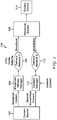
- System 200 includes a transmitter 202 for encoding and broadcasting video content and a receiver 204 for receiving the video content, decoding the video content and providing the decoded video content to a display device.
- Transmitter 202 may typically be included with equipment located at a signal transmission center, such as broadcast affiliate manager 104 described in FIG. 1 .
- the signal produced by transmitter 202 is transmitted over a broadcast network, such as delivery network 1 (106) to receiver 204.
- Receiver 204 may be a set top box, gateway, computer, or other network interface device that is typically located at or near a user's home.
- Receiver 204 may also be included in a mobile device, such as a personal digital assistant, tablet, or cellular telephone.
- the transmitter 202 includes a source for, or otherwise acquires, a full resolution, right view image 206 and a full resolution left view image 208 of a stereo image pair.
- the right view image 206 and left view image 208 may be provided from a content source, such as content source 102 described in FIG. 1 .
- Each of the right view image 206 and left view image 208 are passed to respective sample rate converters 210, 212.
- Sample rate converters 210, 212 convert the horizontal sample rate of each image to one half the original horizontal size.
- the one half size right view image 214 and one half size left view 216 are merged into a single image in an image processor 218.
- the merged image from image processor 218 is then transmitted to encoder 220 where the merged image is encoded in accordance with the Motion Picture Entertainment Groups (MPEG) H.264/MPEG-4 Part 10 standard, the Advanced Video Coding (AVC) standard, or similar compression algorithm, to create first bit stream 222.
- MPEG Motion Picture Entertainment Groups
- AVC Advanced Video Coding
- the acquired full resolution left view image 208 is provided to encoder 224 where the left view image 208 is encoded in accordance with H.264/MPEG-4 Part 10, AVC, or similar compression algorithm, to create a second bit stream 226.
- the two streams may not use the identical compression algorithms.
- encoder 220 may encode the first bit stream 222 using a higher or lower compression rate H.264 algorithm than encoder 224 uses for the second bit stream 226.
- full resolution image 208 is identified as a left view image, its description is for convention purposes only.
- the full resolution image 208 may, instead be identified as aright view image. As a result, it is understood that the descriptions for left view image and right view image signal throughout this disclosure may be reversed.
- the first and second bit streams 222, 226 from encoder 238 and encoder 244 are provided to output signal processor 228.
- Controller 230 creates of determines identification information and provides this information along with any other control information to output signal processor 228. In one embodiment, controller 230 sets a packet ID for each bit stream.
- Output signal processor 228 merges the first and second bit streams 222, 226 into a single bit stream 232 for transmission as part of a signal to the receiving device 204 based on the packet ID information and the control information provided by controller 230.
- Controller 230 also appends additional information to the single bit stream 232 including, but not limited to, an identification bit, an identification byte, or identification packet.
- the controller 230 may create a program guide that is also transmitted as part of the signal to the receiving device using the identification. The inclusion of program guide information allows the receiver 204 to identify the program content that the bit stream 232 contains.
- the receiver 204 processes the incoming signal including bit steam 232, and provides a separation of the content based on the program guide.
- the receiver 204 may include a storage device 237, such as a hard drive or optical disk drive, for recording and playing back audio and video content.
- the processed content is provided to a display device, such as display device 114 described in FIG. 1 .
- the display device may be a conventional 2-D type display or may alternatively be an advanced 3-D display.
- the receiving device 204 may also be incorporated into other systems including the display device itself. In either case, several components necessary for complete operation of the system are not shown in the interest of conciseness, as they are well known to those skilled in the art.
- a signal including content is received in an input signal receiver 234.
- the input signal receiver 234 may be one of several known receiver circuits used for receiving, demodulation, and decoding signals provided over one of the several possible networks including over the air, cable, satellite, Ethernet, fiber and phone line networks.
- the desired input signal may be selected and retrieved in the input signal receiver 234 based on user input provided through a control interface (not shown).
- the output signal from the input signal receiver 234 is provided to an input stream processor 236.
- the input stream processor 236 performs the signal selection and processing, and determines which of the first and second bit streams are to be sent to the proper decoder.
- the input stream processor 236 will distinguish the first and second bit streams based on the program guide sent by device 202 and the packet ID or other identification information for each bit stream (e.g., bit stream 222 and bit stream 226).
- the input stream processor 236 may send the received bit streams to storage device 237.
- the storage device 237 allows later retrieval and playback of the content under the control of a controller 254 and also based on commands, e.g., navigation instructions such as fast-forward (FF) and rewind (Rew), received from a user interface (not shown).
- the storage device 237 may be a hard disk drive, one or more large capacity integrated electronic memories, such as static random access memory, or dynamic random access memory, or may be an interchangeable optical disk storage system such as a compact disk drive or digital video disk drive.
- the input stream processor 236 will separate the bit streams and forward one of the first and second bit streams to the appropriate decoder, either decoder 238 or decoder 244.
- the bit stream will be sent to decoder 238.
- Decoder 238 decodes the merged image in accordance with one or more video compression decoding algorithms, such as H.264/MPEG-4 Part 10 or AVC, to a merged image 240 having a half resolution left and right view.
- the 3D half resolution output 242 is provided to selector 250.
- Controller 254 is used to determine and control which of the bit streams is provided through selector 250 to audio/video interface 252. The operation of the selector 250 and controller 254 will be described below.
- the bit stream will be sent to decoder 244.
- Decoder 244 decodes the left view image 208 in accordance with one or more compression decoding algorithms to generate a left view image 246.
- the left view image is then outputted as a 2D full resolution output signal 248.
- the 2D full resolution output signal 248 is also provided to the selector 250.
- Controller 254 determines a type of a display device coupled to the receiving device 204 via an audio/video interface 252.
- the audio/video interface 252 may be an analog signal interface such as red-green-blue (RGB) or may be a digital interface such as high definition multimedia interface (HDMI).
- the controller 254 communicates with the audio/video interface 252 and receives information from the audio/video interface 252 as to whether a 2D or 3D display device is connected thereto.
- the controller 254 determines the capabilities of the display device by communicating through the HDMI interface with the display device.
- A/V analog audio/video
- the display device setup is normally accomplished with buttons on the receiving device 204 which can be read by the controller, or with user interface screens where a user inputs the display type with a remote control driven selection.
- the controller 254 controls the selector 250 to output the appropriate output signal, either the 3D half resolution video signal or 2D full resolution video signal. For example, if the controller 254 determines a 3D display device is coupled to the audio/video interface 252, the 3D half resolution output 242 will be sent to the audio/video interface 252 via the selector 250. If the controller 254 determines a 2D display device is coupled to the audio/video interface 252, the 2D full resolution output 248 will be sent to the audio/video interface 252 via the selector 250. It is to be appreciated that the above processing may originate from the signals received at the input signal receiver or from content retrieved from the storage device 237.
- controller 230 and controller 254 may be interconnected via a bus to several of the components contained within transmitter 202 and set-top box 204 respectively.
- controller 254 may manage the conversion process for converting the input stream signal into a signal for storage on the storage device 237 or for display on a display device, not shown.
- the controller 254 also manages the retrieval and playback of stored content.
- the controller 230 and controller 254 may further be coupled to a control memory, not shown, (e.g., volatile or non-volatile memory, including random access memory, static RAM, dynamic RAM, read only memory, programmable ROM, flash memory, EPROM, EEPROM, etc.) for storing information and instruction code for controller 230 and controller 254.
- volatile or non-volatile memory including random access memory, static RAM, dynamic RAM, read only memory, programmable ROM, flash memory, EPROM, EEPROM, etc.
- the implementation of the memory may include several possible embodiments, such as a single memory device or, alternatively, more than one memory circuit connected together to form a shared or common memory. Still further, the memory may be included with other circuitry, such as portions of bus communications circuitry, in a larger circuit.
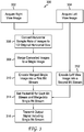
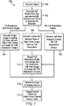
- FIG. 3 a flowchart of an embodiment of a process 300 for encoding half resolution split screen broadcasts is shown.
- Process 300 will primarily be described with respect to the transmitter 202 described in FIG. 2 but may similarly be included in the equipment found in broadcast affiliate manager 104 described in FIG. 1 .
- a full resolution, right view image is acquired.
- a full resolution left view image is acquired.
- the right view and left view image form a stereo image pair and may be provided from a content source, such as content source 102 described in FIG. 1 .
- one of the two images may be generated by a transmitter device, such as transmitter 202, using a 2D image and 2D-3D processing techniques.
- each of the right view image and left view image are converted by changing the horizontal sample rate of each image to one half the original horizontal size.
- the one half size right view image and one half size left view are merged into a single image. It is important to note that each one half size image typically occupies one half of the full horizontal width of the image signal. Alternatively, each half size image may be interspersed in a pattern across the entire image signal, such as in a checkerboard pattern.
- the merged image is then encoded using a video compression encoding algorithm to create a first encoded bit stream.
- the merged image may be encoded in accordance with H.264/MPEG-4 Part 10, AVC, or some similar compression algorithm.
- the full resolution left view image from step 304 is encoded using a video compression encoding algorithm, similar to that described in step 310, to create a second encoded bit stream.
- step 314 information about the first bit stream and second bit stream is retrieved and processed to form one or segments (e.g., bits, bytes, packets) of program information. Also in step 314, the first bit stream and second bit stream are merged to form a single signal or bit stream and the information for the first bit stream and second bit stream is appended to the single bit stream. In one embodiment the information is appended as a program identification (PID). The PID for the single bit stream may also be combined with PIDs from other bit streams to form a separate program guide bit stream.
- an output signal containing the single bit stream is transmitted. The output signal may be transmitted as a transmission signal over a delivery network, such as delivery network 106 described in FIG. 1 .
- the transmission step 316 may also include additional signal processing necessary to transmit the signal, such as additional error correction encoding, modulation coding, digital to analog conversion, filtering, and upconverting of the analog signal.
- the output signal may contain other bit streams as well as additional information, such as a program guide stream. It is important to note that the program guide information may be appended to the single bit stream instead of being created as a separate bit stream.
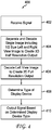
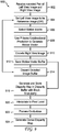
- Process 400 will be primarily described with respect to receiver 204 described in FIG. 2 .
- Process 400 may also be used as part of the operation of a receiving device, such as receiving device 108 described in FIG. 1 .
- a signal containing the desired bit stream (e.g., bit stream 232) as well as other content, is received from a transmission network.
- the signal and the content may be provided by a network service provider, such as broadcast affiliate manager 104 described in FIG. 1 , and received in an input signal receiver, such as receiver 234.
- the content, including the bit stream, such as desired bit stream 232 may also be provided from a storage device, such as storage device 237 or other media device, such as digital versatile disc (DVD) or other media.
- DVD digital versatile disc
- Step 404 the received input signal is separated into multiple bit streams.
- each of first and second bit streams from the desired bit stream 232 is provided to the appropriate decoder.
- Step 404 may include a determination as to whether the bit stream includes the merged image. If the bit stream includes the merged image, the bit stream will be decoded in accordance with one or more video compression decoding algorithms, such as H.264/MPEG-4 Part 10, AVC, or other similar compression decoding process.
- the decoding at step 404 produces a merged image having a half resolution left and right view.
- a similar decoding occurs if one of the separated bit streams includes the full resolution left view image.
- the decoding at step 406 may use a video compression decoding algorithm similar to that described in step 404.
- the type of display device used for displaying the video content is determined.
- the display device is coupled to the set top box 204 via an audio/video interface, such as audio/video interface 252.
- the audio/video interface 252 may be an analog signal interface such as red-green-blue (RGB) or may be a digital interface such as high definition multimedia interface (HDMI).
- the display device may also be integrated with the receiving and processing components in set top 204.
- the determination at step 408 may be performed automatically through a display device identification process, or may be user selected.
- steps 408 and 410 are performed by controller 254 and selector 250. For example, if the controller 254 determines a 3D display device is coupled to the audio/video interface 252, the 3D half resolution output 242 will be sent to the audio/video interface 252 via the selector 250. If the controller 254 determines a 2D display device is coupled to the audio/video interface 252, the 2D full resolution output 248 will be sent to the audio/video interface 252 via the selector 250. Alternatively, steps 408 and 410 may be performed using other elements, such as the audio/video interface 22 or decoders 238 and 244. It is also to be appreciated that the above processing may originate from the signals received at the input signal receiver or from content retrieved from the storage device 237.
- System 500 includes a transmitter 502 for encoding and broadcasting video content and a receiving device 504, e.g., a set-top box, gateway, or other network interface device, for receiving the video content, decoding the video content and providing the decoded video content to a display device.
- Receiving device 504 may also be included in a mobile device, such as a personal digital assistant, tablet, or cellular telephone. Except as described below, both transmitter 502 and receiving device 504 operate and interface with each other in a manner similar to system 200 described in FIG. 2 .
- Transmitter 502 acquires a full resolution right view image and a full resolution left view image of a stereo image pair.
- the full resolution right view image and left view image may be provided from a content source or in some other manner as described above.
- the right view image and left view image are merged into a single image in merging circuit 511 and provided to a sample rate converter 510.
- the sample rate converter 510 converts the horizontal sample rate of the merged image to one half the original horizontal size.
- the output of the sample rate converter 510 provides a converted image 518 to encoder 520.
- Encoder 520 encodes the image using one or more video compression algorithms, such as those described above. Additionally, the acquired full resolution left view image is provided to encoder 524, and encoded using one or more video compression algorithms as described above.
- Output of signal processor 528 operates under the control of controller 530. Controller 530 sets a packet ID, or other stream identification, for each bit stream and the output signal processor 528 merges the first bit stream 522 and second bit stream 526 into a single bit stream 532, along with the packet ID or other stream identification.
- Output signal processor 528 provides an output signal, including bit stream 532, that is transmitted from transmitter 502 to receiving device 504. Additionally, controller 530 creates a program guide that is also transmitted to the receiving device 504.
- the program guide may include the packet ID or other information about output stream 532, as well as information about other bit streams transmitted to receiving device 504.
- the program guide is used to inform the receiving device 504 what bit stream 532, as well as any other bit streams included and transmitted as part of the output signal, contains.
- the program guide may be transmitted as a separate bit stream or may be appended to output bit stream 532.
- the receiving device 504 processes the bit steam 532, and provides a separation of the content based on the program guide.
- the receiving device 504 may include a storage device, such as a hard drive or optical disk drive, for recording and playing back audio and video content.
- the processed content is provided to a display device, such as display device 114 described in FIG. 1 .
- the display device may be a conventional 2-D type display or may alternatively be an advanced 3-D display.
- the receiving device 504 may also be incorporated into other systems including the display device itself. In either case, several components necessary for complete operation of the system are not shown in the interest of conciseness, as they are well known to those skilled in the art.
- the received signal including content such as bit stream 532, is received in an input signal receiver 534.
- the input signal receiver 534 may be one of several known receiver circuits used for receiving, demodulation, and decoding signals provided over one of the several possible networks including over the air, cable, satellite, Ethernet, fiber and phone line networks.
- the desired input signal may be selected and retrieved in the input signal receiver 534 based on user input provided through a control interface (not shown).
- the output signal from the input signal receiver 534 is provided to an input stream processor 536.
- the input stream processor 536 performs the signal selection and processing, and determines which of the first and second bit streams are to be sent to the proper decoder, either decoder 538 or decoder 544.
- the input stream processor 536 identifies and distinguishes the first and second bit streams based on the program guide information sent by device 502 and the identification of the packet ID, or other stream identification, for a received bit stream, such as bit stream 532. Additionally, the input stream processor 536 may send the received bit streams, if necessary, to a storage device 537, as described above.
- the input stream processor 536 will separate the bit streams and, if identified or distinguished, provide one of the first and second bit streams to the appropriate decoder, either decider 538 or decoder 544.
- the input stream processor 536 determines that the bit stream includes the merged image bit stream (e.g., bit stream 522), then the merged image bit stream will be sent to decoder 538.
- Decoder 538 decodes the merged image bit stream using a video compression algorithm in accordance with H.264/MPEG-4 Part 10, AVC (Advanced Video Coding), or other algorithm. Decoder 538 produces a 3D half resolution output image signal 542 that is a merged image 540 having a half resolution left and right view.
- the 3D half resolution output 542 is provided to selector 550 which is under control of controller 554.
- the operation of the selector 550 and controller 554 are similar to the selector and controller described above in relation to FIG. 2 .
- the input stream processor 536 determines, identifies, or distinguishes that the bit stream including the full resolution left view image (e.g., bit stream 526) is provided as part of the received signal, this bit stream is provided to decoder 544.
- the left view image is decoded in accordance with H.264/MPEG-4 Part 10, AVC, or other decoding process to produce a 2D full resolution output signal 548 that is a left view image 546.
- the 2D full resolution output signal 548 from decoder 544 like the output of decoder 538, is also sent to the selector 550, which is under control of the controller 554.
- the half resolution right view portion of the 3D half resolution output signal 542 is also provided to sample rate converter 556.
- Sample rate converter 556 upconverts the horizontal sample rate of the right view portion of the image to back to full resolution.
- the entire 3D half resolution output signal 542 may be provided to sample rate converter 556.
- Sample rated converter 556 may operated to discard the left view portion of the signal before upconverting the right view portion.
- the upsampled right view image may be a 1080i horizontal split image or 720p vertical split image.
- the upconverted right view image signal is provided along with the 2D full resolution output signal 548 from decoder 544 to the merging circuit 557.
- Merging circuit 557 combines the upconverted right view image with the full resolution left view image to produce left and right full resolution output signal 558.
- the full resolution output signal is also provided to selector 550, which is under the control of controller 554.
- sample rate conversion may also be performed on the 2D full resolution output signal 548.
- the 2D full resolution output signal 548 may be 1080i format, while the upconverted right portion signal may be 720P.
- a sample rate conversion of the 2D full resolution output signal 548 from 1080i to 720P may be necessary.
- the sample rate conversion may be performed in decoder 544, or may be performed in a separate sample rate converter, not shown.
- an additional sample rate conversion of the left view image portion of 3D half resolution output signal 542 may also be performed along with the right view image portion in sample rate converter 556, the use of the 2D full resolution output signal 548 for the left view image results in a higher visual quality image.
- the process of sample rate conversion may be produce noticeable artifacts, such as image errors or distortions.
- the 2D full resolution output signal 548 the viewer may be less aware of the sample rate conversion artifacts because these artifacts may only be present in the right eye view.
- Controller 554 determines a type of a display device coupled to the receiving device 504 via an audio/video interface 552.
- the audio/video interface 552 may be an analog signal interface such as red-green-blue (RGB) or may be a digital interface such as high definition multimedia interface (HDMI).
- the controller 554 communicates with the audio/video interface 552 and receives information from the audio/video interface 552 as to whether a 2D display device, 3D legacy display device or 3D full resolution display device is connected thereto. Based on the type of the display device, the controller 554 controls the selector 550 to output the appropriate output signal.
- the controller 554 determines a legacy 3D display device is coupled to the audio/video interface 552, the 3D half resolution output 542 will be sent to the audio/video interface 552 via the selector 550. If the controller 554 determines a 2D display device is coupled to the audio/video interface 552, the 2D full resolution output 548 will be sent to the audio/video interface 552 via the selector 550. If the controller 554 determines a full resolution 3D display device is coupled to the audio/video interface 552, the 3D full resolution output 558 will be sent to the audio/video interface 552 via the selector 550. It is to be appreciated that the above processing may originate from the signals received at the input signal receiver or from content retrieved from the storage device 537.
- Process 600 will primarily be described with respect to the transmitter 502 described in FIG. 5 but may similarly be described with respect to transmitter 202 described in FIG. 2 or may be included in the equipment found in broadcast affiliate manager 104 described in FIG. 1 .
- a full resolution, right view image is acquired.
- a full resolution left view image is acquired.
- the right view and left view image form a stereo image pair and may be provided from a content source, such as content source 102 described in FIG. 1 .
- one of the two images may be generated by a transmitter device, such as transmitter 502, using a 2D image and 2D-3D processing techniques.
- each of the right view image and left view image are converted by changing the horizontal sample rate of each image to one half the original horizontal size.
- the one half size right view image and one half size left view are merged into a single image. It is important to note that each one half size image typically occupies one half of the full horizontal width of the image signal. Alternatively, each half size image may be interspersed in a pattern across the entire image signal, such as in a checkerboard pattern.
- the sample rate conversion at step 606 and merging at step 608 should be performed to create a merged single image that is in a 1080p format.
- the highest possible video quality for the merged image signal is maintained and transmitted for use by a receiver, such as receiving device 504.
- the merged image is then encoded using a video compression encoding algorithm to create a first encoded bit stream.
- the merged image may be encoded in accordance with H.264/MPEG-4 Part 10, AVC, or some similar compression algorithm.
- the full resolution left view image from step 604 is encoded using a video compression encoding algorithm, similar to that described in step 610, to create a second encoded bit stream.
- step 614 information about the first bit stream and second bit stream is retrieved and processed to form one or segments (e.g., bits, bytes, packets) of program information. Also in step 614, the first bit stream and second bit stream are merged to form a single signal or bit stream and the information for the first bit stream and second bit stream is appended to the single bit stream. In one embodiment the information is appended as a program identification (PID). The PID for the single bit stream may also be combined with PIDs from other bit streams to form a separate program guide bit stream. Finally, at step 616, an output signal containing the single bit stream is transmitted. The output signal may be transmitted as a transmission signal over a delivery network, such as delivery network 106 described in FIG. 1 .
- a delivery network such as delivery network 106 described in FIG. 1 .
- the transmission step 616 may also include additional signal processing necessary to transmit the signal, as described earlier.
- the output signal may contain other bit streams as well as additional information, such as a program guide stream. It is important to note that the program guide information may be appended to the single bit stream instead of being created as a separate bit stream.
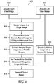
- Process 700 will be primarily described with respect to receiving device 504 described in FIG. 5 but may similarly be described with respect to receiver 202 described in FIG. 2 .
- Process 700 may also be used as part of the operation of a receiving device, such as receiving device 108 described in FIG. 1 .
- a signal containing desired video content in a bit stream, as well as other content, is received from a transmission network.
- the signal and the content may be provided by a network service provider, such as broadcast affiliate manager 104 described in FIG. 1 , and received in an input signal receiver, such as receiver 534.
- the content, including the bit stream may also be provided from a storage device, such as storage device 237 or other media device, such as digital versatile disc (DVD) or other media.
- DVD digital versatile disc
- the received input signal is separated into multiple bit streams.
- the separation step 703 includes identification of the individual bit streams, such as a determination and identification of a first bit stream as a merged half resolution 3D video image and identifying a second bit stream as a full resolution 2D image as a left view image.
- the separation step 703 also provides each of the identified first and second bit streams from the desired bit stream to the appropriate decoder.
- the first bit stream, a half resolution 3D video signal is decoded in accordance with one or more video compression decoding algorithms, such as H.264/MPEG-4 Part 10, AVC, or other similar compression decoding process.
- the half resolution 3D signal may be in several formats, including a split screen 3D video signal or a checkerboard video signal.
- the decoding at step 704 produces a merged image having a half resolution left and right view.
- a similar decoding occurs for the second bit stream, a 2D full resolution image signal.
- the decoding at step 706 may use a video compression decoding algorithm similar to that described in step 704.
- the right view portion of the half resolution merged image signal is sample rate converted to produce a full size and full resolution right view image signal.
- the right view image signal is a full resolution signal, it is understood that the sample rate conversion will introduce image artifacts to the full resolution right view image.
- the decoded and converted full resolution right view image generated in step 708 and the decoded full resolution left view image are merged into a single full resolution 3D output signal. It is important to note that the single full resolution 3D output signal from step 710, the half resolution 3D output signal from step 704, and the full resolution 2D (left view) output signal from step 706 are available and provided for display.
- the type of display device used for displaying one of the output signals generated above is determined.
- the display device is coupled to the receiving device 504 via an audio/video interface, such as audio/video interface 552.
- the determination at step 712 may be performed automatically through a display device identification process, or may be user selected.
- a 2D display device if a 2D display device is used, the full resolution 2D output signal is selected.
- a 3D display device is used, either the half resolution 3D resolution output signal or the full resolution 3D output signal is selected.
- the choice of a half resolution or a full resolution 3D output signal may be made by a user through a user interface selection.
- the full resolution 3D output signal is always selected if it available, as determined in step 703.
- the selected output signal either a 2D full resolution left view image signal, a half resolution 3D left view and right view image signal, or a full resolution 3D left view and right view image signal, is provided to the display device.
- system 500, process 600, and process 700 are described as operating on a half resolution 3D left view and right view image signal, other partial, or reduced, resolution 3D signals may also be used.
- 3D signal including a reduced resolution (other than half) left view image and a reduced resolution (other than half) right view image may be used, with the resolution of the left view image being different from the resolution of the right view image.
- Certain steps in process 800 may be modified or omitted based on a specific implementation.
- the display determination step 712 may be performed prior to the decoding steps 704 and 706. Based on the type of display device used, one or the other of decoding steps may be omitted or disabled.
- a system and method for legacy three dimensional (3D) broadcasts, legacy 2D broadcasts and full resolution 3D broadcasts has been described.
- the receiving device 504 will decode the legacy 2D broadcast for the left eye view and the legacy 3D split screen broadcast.
- the full resolution right view is created by scaling the right half of legacy 3D split screen broadcast. In this manner, full resolution 3D may be provided with no new compression techniques required.
- the embodiments in FIGs. 2-7 relate to receiving and processing the bit streams used for 3D broadcasts includes receiving a data signal that includes two different bit streams merged into the data signal.
- the first video signal represents a two-dimensional image at a first video resolution and the second video signal represents a three-dimensional image at a second resolution.
- the embodiments also include decoding the first video signal if an output display type is a two-dimensional display type, decoding the second video signal if the output display type is a first three-dimensional display type, and decoding the first video signal and second video signal simultaneously if the output display type is a second three-dimensional display type.
- the embodiments in FIGs. 2-7 also relate to processing a received signal to provide a 3D video output.
- the embodiments include receiving a signal, the signal including a first video signal representing a two-dimensional image at a first video resolution and a second video signal representing a three-dimensional image at a second resolution, determining a type of display device for viewing video content, decoding the first video signal, decoding the second video signal, and providing an output signal to the display device, the output signal including a combination of the first decoded video signal and a portion of the second decoded video signal if the type of display device is a three dimensional display device.
- a system and method for user adjustable disparity mapping in a receiving device uses an H.264 encoder in the receiving device to assist in generating a dense disparity mapping of a received and decoded pair of stereo images, i.e., a right view image and a left view image.
- the two images are aligned consecutively in time and passed through the encoder to generate encoding information such as motion vectors.
- the resulting motion information is used to generate a disparity map that can be used as a user control for adjusting the image depth in the stereo image set.
- Such a system is useful if the signal transmission includes sending stereoscopic images but omits transmission of a depth map.
- FIG. 8 an exemplary embodiment of a receiving device 800 for generating a dense disparity map is shown. It is to be appreciated that, except as described below, elements similar to those described above in relation to FIGS. 2 and 5 will not be described in detail.
- input signal receiver 834, input stream processor 836, storage device 837, decoders 838 and 844 and sample rate converter 856 perform substantially as described above to provide the 3D half resolution output 842, the 2D full resolution output 848 and 3D full resolution output 858 to the selector 850.
- Receiving device 800 further includes an encoder 860 coupled to the output of selector 850.
- Encoder 860 is also coupled to memory 862.
- Controller 854 is also coupled to encoder 860 as well as memory 862.
- a user interface 870 is coupled to controller 854.
- encoder 860 receives the decoded pair of left view and right view images and stores the images in the coded image buffer 864, shown as portion of memory 862.
- the encoder 860 sets the left view image to be the reference image, also known as an instantaneous decode refresh (IDR) frame.
- IDR instantaneous decode refresh
- Encoder 860 apportions the reference image to select 4 pixel by 4 pixel (4x4) motion blocks and use P-frame unidirectional prediction to generate a motion vector for each 4x4 sub-block of the right view image. It is important to note that the use of a 4 pixel by 4 pixel block is based on standard practice.
- the motion vector for each 4x4 block is used to encode the right view image which is stored in the coded image buffer 864. Since the desired output of the encode process is the motion vectors rather than the actual coded image the motion vectors are extracted from the coded image signal and stored in a motion vector buffer 866, also shown as part of memory 862. The information stored in coded image buffer 864 following creation and storage of the motion vectors in motion vector buffer 866. As necessary, encoder 860 steps through the remaining portions of the image signal to encode the next image pair until all images pairs are processed.
- coded image buffer 864 and motion buffer 866 may reside on a single, shared memory device 862 or may be separate individual buffers.
- an arbiter 863 is included.
- Arbiter 863 arbitrates, or manages, access to the shared memory elements of memory 862.
- FIG. 8 only shows two clients (i.e., encoder 860 and controller 854) accessing memory device 862, in most practical systems there are several independent clients all trying to access the same memory device, such as memory device 862.
- memory access may be individually controlled or controlled by a controller similar to control 854. It is the function of the arbiter 863 to make sure each client gets access at an assigned level of priority and with sufficient bandwidth and low enough latency to accomplish the task assigned to each of the functional units.
- the signal stored in motion vector buffer 866 is filtered to remove any vertical component of any generated motion vector.
- the filtered result is used as an indication, with picture level granularity of four pixel by four pixel image regions, of the horizontal disparity between the left view and right view pictures.
- This filtered result represented as a numerical entry, or as some other quantifiable difference indicator, is stored in disparity buffer 868, also shown as part of memory device 862. It is to be appreciated that although the above functions are illustrated and described as being performed by encoder 860, one or more of the functions could also be implemented by controller 854 or by fixed function hardware or a combination of hardware and software.
- the array of horizontal disparity values stored in disparity buffer 868 may be further filtered (e.g., spatially) by taking into account the differences in value between horizontally adjacent disparity values. For example, consider a 4x4 picture block B with a 4x4 picture block A to its immediate left and a 4x4 picture block C to its immediate right. If the disparity between left and right picture views at block A is 6, and if the disparity between left and right picture views at block B is 4, and if the disparity between left and right picture views at block C is 2, then a gradual shift is indicated in the disparity as a function of the progression from the left spatial position in the image pair to the right spatial position in the image pair.
- the controller 854 can interpolate across 4x4 picture block B assigning the left-most pixels with a disparity between 4 and 6 and the right most pixels with a disparity between 4 and 2.
- this example only looks at, or incorporated and processes, one 4x4 region to the left and right, other filters could be employed that incorporate further regions in either direction.
- the same filter principles may be applied in the vertical direction to create and process a disparity map with pixel level granularity.
- encoder 860 As needed, encoder 860, or alternatively the controller 854, generates an occlusion map.
- Sharp changes in disparity value between horizontally or vertically adjacent 4x4 blocks provide an indication of the existence of edges between near field objects and far field objects in the stereo image pair. On these edges, it is typically the case that the left eye is able to see part of the near field object that is blocked from view for the right eye; and likewise the right eye will have a view of part of the object which is blocked for the left eye.
- These areas of visual mutual exclusivity of view between the left and right eyes create occlusions which can be detected while processing the disparity vectors and signaled to a later image processing step.
- the pixel level disparity map described above and the occlusion map form a dense disparity map. It is to be appreciated that there are several techniques known in the art to generate a dense disparity map from the pixel level disparity map and the occlusion map.
- a dense disparity map of a stereo video signal reveals the convergence depth of every pixel pair within the stereo image pair.
- the receiving device 800 is able to determine how and where in the picture graphics overlays can be presented in order to avoid unpleasant depth conflicts between video and graphics.
- the dense disparity map can be used in order to allow receiving device 800 to modify the perceived 3D depth of a stereo image by applying a disparity and occlusion aware scaling algorithm to one or both pictures of the stereo pair. This enables receiving device 800 to implement features such as user controlled 3D depth.
- Depth scaling using disparity and occlusion aware scaling permits easy modification of the range of perceived depth in the stereo image pair.
- the range of depth in an image may be identified as the perceived distance between the furthest object behind the plane of the image rendering surface and the object furthest in front of the plane of the image rendering surface.
- This depth range represents a visual stereoscopic 'volume'.
- the user may control this visual stereoscopic 'volume' with a simple user control, such as an up/down control via user interface 870. The control may be used to increase or decrease the perceived range of depth in the stereo image.
- User interface 870 may be any known user interface including, but not limited to, a remote control device, a plurality of buttons disposed on the receiving device 804, a user preference screen generated by the receiving device 804 and displayed on a display device, etc. Therefore, by generating a dense disparity map in the receiving device 804, user controlled depth scaling can be achieved.
- FIG. 9 a flowchart of an exemplary process 900 for generating the dense disparity map is shown.
- the steps of process 900 may be performed in receiving device 800.
- the steps of process 900 may similarly be performed in other receivers or set top box devices, such as receiver 204 described in FIG. 2 or receiving device 504 described in FIG. 5 .
- the decoded pair of left view and right view images are received.
- the decoded pair of left and right view images are provided by a selector and may be a half resolution 3D image signal or a full resolution 3D image signal.
- the full resolution 3D image signal may include a sample rate converted portion of the half resolution 3D image signal as described above.
- Step 902 may also include storing the images in memory, such as the coded image buffer 864.
- the left view image is set to be the reference image or IDR. Although either image may be set as the reference image, it is advantageous to use the left view image because, as described above, the left view image is a full resolution image, thus reducing or eliminating the presence of image artifacts in the reference image.
- the size and apportioning of motion blocks is selected. As described above, the motion block size may be 4x4 pixels, however, other block sizes are possible.
- motion vectors are generated using P-frame unidirectional prediction for each of the corresponding sub-blocks of the right view image with reference to the left view image.
- the generated motion vectors for the sub-blocks are used to encode the right view image.
- the final set of motion vectors from steps 908 and 910 is stored in a memory, such as motion vector buffer 866.
- a memory such as motion vector buffer 866.
- the left and right view images are processed as if they exist temporally rather than spatially. In other words, although the left and right images are intended to be viewed simultaneously in time, the motion processing is performed as if the left and right view images occurred consecutively in time.
- step 914 the contents of the memory storing the encoded images (e.g., coded image buffer 864) are discarded, or erased, since the desired output of the encode process steps described above is the motion vectors rather than the actual coded image the motion vectors.
- process 900 returns to step 904 to encode any remaining image pairs or portions until all images pairs are encoded and motion vectors processed.
- a granular disparity map is generated and stored by filtering sets of motion vectors.
- the granular disparity map is an indication, with picture level granularity of equal to sub-block size selected at step 906, of the horizontal disparity between the left view and right view pictures.
- the motion vectors for a set of three consecutively located motion sub-blocks are compared and quantified to determine adjacent disparity values.
- the array of horizontal disparity values may then be further filtered, or interpolated, at step 920, by taking into account the differences in value between horizontally adjacent disparity values and further interpolated vertically in a manner similar to that described above to determine a pixel level disparity map.
- an occlusion map is generated.
- any changes in disparity value between horizontally or vertically adjacent blocks may be an indication of edges between near field and far field objects in the stereo image pair.
- the occlusion map may be generated at step 922 using either the original motion vectors stored at step 912, or the disparity maps generated at steps 916 and/or 920. In the latter, the occlusion map may be generated from the motion vectors by filtering or interpolating the motion vectors in a manner to reinforce the presence of edges.
- the pixel level disparity map generated at step 920 and the occlusion map generated at step 922 are combined to form a dense disparity map.
- the dense disparity may be used to permit such features as a user adjustable depth range in the 3D image.
- the embodiments described in FIGs. 8 and 9 relate to generating a dense disparity map in a receiving device.
- the embodiments include receiving a signal that includes a desired bit stream.
- the desired bit stream may further include, and be separated into one or more bit streams representing a 2D full resolution image signal as a single left eye or right eye image and a 3D partial or reduced (e.g., half) resolution image signal containing a reduced resolution left eye image and a reduced resolution right eye image.
- the bit streams are decoded in order to produce a signal having a left eye image and a right eye image, either at full or reduced resolution.
- the embodiments further describe encoding the left eye image as a reference image, predictively coding the right eye image using the coded left eye image as the reference image, capturing motion indicators generated during encoding of the right eye image, and generating a dense disparity map between the left eye image and right eye image using the motion indicators.
Claims (4)
- Verfahren, das die folgenden Schritte umfasst:Empfangen (702) eines Datensignals, wobei das Datensignal ein erstes Videosignal und ein zweites Videosignal enthält, wobei das erste Videosignal ein zweidimensionales Bild umfasst, wobei das zweidimensionale Bild ein erstes linkes bzw. rechtes Ansichtsbild eines dreidimensionalen stereoskopischen Bilds mit einer ersten Videoauflösung ist;Bestimmen (712) eines Ausgabeanzeigetyps zum Betrachten von Videoinhalt;Decodieren (706) des ersten Videosignals;Decodieren (704) des zweiten Videosignals;Ausgeben (714) eines decodierten Signals auf der Grundlage des Ausgabeanzeigetyps;dadurch gekennzeichnet, dassdas zweite Videosignal ein dreidimensionales stereoskopisches Bild mit verringerter Auflösung umfasst, das ein von dem ersten linken bzw. rechten Ansichtsbild ausgegebenes linkes bzw. rechtes Ansichtsbild mit verringerter Auflösung und ein rechtes bzw. linkes Ansichtsbild mit verringerter Auflösung, jedes mit einer selben niedrigeren Auflösung als die erste Videoauflösung, enthält;und dadurch, dass das Verfahren ferner umfasst:gleichzeitiges Decodieren (706, 704) des ersten Videosignals und des zweiten Videosignals, wobei der Schritt des Decodierens des ersten und des zweiten Videosignals das Aufwärtsabtasten (708) des rechten bzw. linken Ansichtsbilds mit verringerter Auflösung auf die erste Videoauflösung enthält;und Vereinigen (710) des decodierten ersten Videosignals und des decodierten und aufwärtsabgetasteten rechten bzw. linken Ansichtsbilds mit verringerter Auflösung, um ein zweites dreidimensionales Bild mit der ersten Videoauflösung zu erhalten;wobei das ausgegebene decodierte Signal Folgendes ist:das decodierte erste Videosignal, falls der Ausgabeanzeigetyp ein zweidimensionaler Anzeigetyp ist;das decodierte zweite Videosignal, falls der Ausgabeanzeigetyp ein erster dreidimensionaler Anzeigetyp ist,das vereinigte Videosignal, falls der Ausgabeanzeigetyp ein zweiter dreidimensionaler Anzeigetyp ist.
- Verfahren nach Anspruch 1, wobei das linke bzw. rechte Ansichtsbild mit verringerter Auflösung und das rechte bzw. linke Ansichtsbild mit verringerter Auflösung eine halbe horizontale Auflösung der ersten Videoauflösung aufweisen.
- Verfahren nach Anspruch 1, wobei die Schritte des Empfangens des Datensignals und des Decodierens in einer Set-Top-Box ausgeführt werden.
- Vorrichtung zum Verarbeiten von Inhalt, wobei die Vorrichtung umfasst:einen Signalempfänger (534), der ein Datensignal (532) empfängt, wobei das Datensignal ein erstes Videosignal (526) und ein zweites Videosignal (522) enthält,wobei das erste Videosignal (526) ein zweidimensionales Bild umfasst, wobei das zweidimensionale Bild ein erstes linkes bzw. rechtes Ansichtsbild eines dreidimensionalen stereoskopischen Bilds mit einer ersten Videoauflösung ist;mindestens einen Decodierer (538, 544), der konfiguriert ist zum:
gleichzeitigen Decodieren des ersten Videosignals und des zweiten Videosignals (540, 546);eine Schnittstelle (552), die mit dem mindestens einen Decodierer (538, 544) gekoppelt ist und dafür konfiguriert ist, ein decodiertes Signal (542, 548, 558) zu empfangen und das decodierte Signal (550) an eine Anzeigevorrichtung auszugeben, wobei die Schnittstelle (552) dafür konfiguriert ist, einen Ausgabeanzeigetyp zu bestimmen;dadurch gekennzeichnet, dassdas zweite Videosignal ein dreidimensionales stereoskopisches Bild mit verringerter Auflösung umfasst, das ein von dem ersten linken bzw. rechten Ansichtsbild ausgegebenes linkes bzw. rechtes Ansichtsbild mit verringerter Auflösung und ein rechtes bzw. linkes Ansichtsbild mit verringerter Auflösung, jedes mit einer selben niedrigeren Auflösung als die erste Videoauflösung, enthält;und dadurch, dass die Vorrichtung ferner umfasst:einen Abtastratenumsetzer, der dafür konfiguriert ist, das rechte bzw. linke Ansichtsbild mit verringerter Auflösung auf eine erste Videoauflösung aufwärtsabzutasten (556) und das decodierte erste Videosignal (546) und das decodierte und aufwärtsabgetastete rechte bzw. linke Ansichtsbild (557) mit verringerter Auflösung zu vereinigen (558), um ein zweites dreidimensionales Bild mit der ersten Videoauflösung (558) zu erhalten;wobei das ausgegebene decodierte Signal (550) Folgendes ist:das decodierte erste Videosignal, falls der Ausgabeanzeigetyp ein zweidimensionaler Anzeigetyp ist;das decodierte zweite Videosignal, falls der Ausgabeanzeigetyp ein erster dreidimensionaler Anzeigetyp ist,das vereinigte Videosignal, falls der Ausgabeanzeigetyp ein zweiter dreidimensionaler Anzeigetyp ist.
Applications Claiming Priority (2)
| Application Number | Priority Date | Filing Date | Title |
|---|---|---|---|
| US30471810P | 2010-02-15 | 2010-02-15 | |
| PCT/US2011/024831 WO2011100735A1 (en) | 2010-02-15 | 2011-02-15 | Apparatus and method for processing video content |
Publications (2)
| Publication Number | Publication Date |
|---|---|
| EP2537347A1 EP2537347A1 (de) | 2012-12-26 |
| EP2537347B1 true EP2537347B1 (de) | 2019-06-05 |
Family
ID=43897306
Family Applications (1)
| Application Number | Title | Priority Date | Filing Date |
|---|---|---|---|
| EP11706395.8A Active EP2537347B1 (de) | 2010-02-15 | 2011-02-15 | Vorrichtung und verfahren zur bearbeitung von videoinhalten |
Country Status (7)
| Country | Link |
|---|---|
| US (2) | US9077966B2 (de) |
| EP (1) | EP2537347B1 (de) |
| JP (1) | JP6013920B2 (de) |
| KR (1) | KR101787133B1 (de) |
| CN (1) | CN102763421B (de) |
| BR (1) | BR112012020471B1 (de) |
| WO (1) | WO2011100735A1 (de) |
Families Citing this family (24)
| Publication number | Priority date | Publication date | Assignee | Title |
|---|---|---|---|---|
| CN102484729B (zh) | 2009-04-07 | 2016-08-24 | Lg电子株式会社 | 广播发送器、广播接收器及其3d视频数据处理方法 |
| US20120314023A1 (en) * | 2010-02-24 | 2012-12-13 | Jesus Barcons-Palau | Split screen for 3d |
| US9930316B2 (en) * | 2013-08-16 | 2018-03-27 | University Of New Brunswick | Camera imaging systems and methods |
| US9521418B2 (en) | 2011-07-22 | 2016-12-13 | Qualcomm Incorporated | Slice header three-dimensional video extension for slice header prediction |
| US11496760B2 (en) | 2011-07-22 | 2022-11-08 | Qualcomm Incorporated | Slice header prediction for depth maps in three-dimensional video codecs |
| US9288505B2 (en) | 2011-08-11 | 2016-03-15 | Qualcomm Incorporated | Three-dimensional video with asymmetric spatial resolution |
| EP2742693A4 (de) * | 2011-08-12 | 2015-04-08 | Motorola Mobility Inc | Verfahren und vorrichtung zur kodierung und übertragung von 3d-videosequenzen in einem drahtlosen kommunikationssystem |
| CN102271272B (zh) * | 2011-08-19 | 2014-12-17 | 深圳超多维光电子有限公司 | 2d图像和3d图像的图像数据存储、传输方法和装置 |
| JP2013066075A (ja) * | 2011-09-01 | 2013-04-11 | Sony Corp | 送信装置、送信方法および受信装置 |
| JP5813236B2 (ja) | 2011-09-16 | 2015-11-17 | ドルビー ラボラトリーズ ライセンシング コーポレイション | フレーム互換なフル解像度立体視3d圧縮および復元 |
| US9485503B2 (en) | 2011-11-18 | 2016-11-01 | Qualcomm Incorporated | Inside view motion prediction among texture and depth view components |
| CN102413350B (zh) * | 2011-11-30 | 2014-04-16 | 四川长虹电器股份有限公司 | 蓝光3d视频处理方法 |
| WO2013089770A1 (en) | 2011-12-16 | 2013-06-20 | Intel Corporation | Resolution loss mitigation for 3d displays |
| CN103379357B (zh) * | 2012-04-26 | 2015-12-16 | 联咏科技股份有限公司 | 图像处理装置 |
| CN104662898A (zh) * | 2012-08-17 | 2015-05-27 | 摩托罗拉移动有限责任公司 | 从三维视频回退 |
| US10264241B2 (en) * | 2013-02-12 | 2019-04-16 | Comcast Cable Communications, Llc | Complimentary video content |
| WO2015016913A1 (en) * | 2013-07-31 | 2015-02-05 | Empire Technology Development Llc | Encoding scheme |
| US9348495B2 (en) | 2014-03-07 | 2016-05-24 | Sony Corporation | Control of large screen display using wireless portable computer and facilitating selection of audio on a headphone |
| JP2016032227A (ja) * | 2014-07-29 | 2016-03-07 | 日立マクセル株式会社 | 映像表示システム、三次元映像ポインティング装置、および映像表示装置 |
| KR102288087B1 (ko) * | 2014-11-25 | 2021-08-10 | 엘지전자 주식회사 | 멀티미디어 디바이스 및 그 제어 방법 |
| WO2018101514A1 (ko) * | 2016-12-01 | 2018-06-07 | 엘지전자 주식회사 | 영상표시장치, 및 이를 구비하는 영상표시 시스템 |
| CN108833878A (zh) * | 2018-06-15 | 2018-11-16 | 深圳超多维科技有限公司 | 视频拍摄方法、装置及系统 |
| CN108769643A (zh) * | 2018-06-15 | 2018-11-06 | 深圳超多维科技有限公司 | 视频拍摄方法、装置及系统 |
| KR102581186B1 (ko) | 2018-10-12 | 2023-09-21 | 삼성전자주식회사 | 전자 장치 및 전자 장치의 제어 방법 |
Citations (2)
| Publication number | Priority date | Publication date | Assignee | Title |
|---|---|---|---|---|
| EP1739979A2 (de) * | 2005-07-02 | 2007-01-03 | Samsung Electronics Co., Ltd. | Verfahren und Vorrichtung zur Kodierung und Dekodierung von Videodaten zur Erzeugung lokaler dreidimensionaler Videobilder |
| WO2009133714A1 (ja) * | 2008-05-01 | 2009-11-05 | パナソニック株式会社 | 立体視映像を再生するための光ディスク |
Family Cites Families (25)
| Publication number | Priority date | Publication date | Assignee | Title |
|---|---|---|---|---|
| US5612735A (en) | 1995-05-26 | 1997-03-18 | Luncent Technologies Inc. | Digital 3D/stereoscopic video compression technique utilizing two disparity estimates |
| JP4056154B2 (ja) | 1997-12-30 | 2008-03-05 | 三星電子株式会社 | 2次元連続映像の3次元映像変換装置及び方法並びに3次元映像の後処理方法 |
| JP3365333B2 (ja) * | 1999-03-03 | 2003-01-08 | 日本電気株式会社 | 解像度変換装置 |
| KR100397511B1 (ko) * | 2001-11-21 | 2003-09-13 | 한국전자통신연구원 | 양안식/다시점 3차원 동영상 처리 시스템 및 그 방법 |
| KR100523052B1 (ko) * | 2002-08-30 | 2005-10-24 | 한국전자통신연구원 | 다중 디스플레이 방식을 지원하는 다시점 동영상의 객체 기반 부호화 장치 및 그 방법과 그를 이용한 객체 기반 송수신 시스템 및 그 방법 |
| KR100523930B1 (ko) | 2003-01-13 | 2005-10-26 | 전자부품연구원 | 다시점 영상의 압축/복원장치 |
| US7046306B2 (en) * | 2003-03-31 | 2006-05-16 | Texas Instruments Incorporated | Processing a video signal using motion estimation to separate luminance information from chrominance information in the video signal |
| KR100556826B1 (ko) * | 2003-04-17 | 2006-03-10 | 한국전자통신연구원 | Mpeg-4 기반의 양안식 3차원 동영상을 서비스하기 위한 인터넷 방송 시스템 및 그 방법 |
| US7515759B2 (en) * | 2004-07-14 | 2009-04-07 | Sharp Laboratories Of America, Inc. | 3D video coding using sub-sequences |
| EP1781046A4 (de) * | 2004-08-18 | 2010-01-20 | Sharp Kk | Bilddaten-anzeigevorrichtung |
| JP4602737B2 (ja) | 2004-10-25 | 2010-12-22 | シャープ株式会社 | 映像表示装置 |
| KR100813961B1 (ko) * | 2005-06-14 | 2008-03-14 | 삼성전자주식회사 | 영상 수신장치 |
| JP2007066012A (ja) * | 2005-08-31 | 2007-03-15 | Toshiba Corp | 映像描画装置、方法およびプログラム |
| US7742046B2 (en) * | 2005-08-31 | 2010-06-22 | Kabushiki Kaisha Toshiba | Method, device, and program for producing elemental image array for three-dimensional image display |
| JP4706638B2 (ja) | 2006-09-29 | 2011-06-22 | セイコーエプソン株式会社 | 表示装置、画像処理方法並びに電子機器 |
| US8594180B2 (en) * | 2007-02-21 | 2013-11-26 | Qualcomm Incorporated | 3D video encoding |
| KR101345303B1 (ko) | 2007-03-29 | 2013-12-27 | 삼성전자주식회사 | 스테레오 또는 다시점 영상의 입체감 조정 방법 및 장치 |
| KR100839429B1 (ko) | 2007-04-17 | 2008-06-19 | 삼성에스디아이 주식회사 | 전자 영상 기기 및 그 구동방법 |
| US8373744B2 (en) | 2007-06-07 | 2013-02-12 | Reald Inc. | Stereoplexing for video and film applications |
| MY162861A (en) * | 2007-09-24 | 2017-07-31 | Koninl Philips Electronics Nv | Method and system for encoding a video data signal, encoded video data signal, method and system for decoding a video data signal |
| KR20090035427A (ko) | 2007-10-05 | 2009-04-09 | 한국전자통신연구원 | 단일시점 또는 다시점 비디오 부호화와 복호화 방법 및 그 장치 |
| WO2009091383A2 (en) | 2008-01-11 | 2009-07-23 | Thomson Licensing | Video and depth coding |
| JP5338166B2 (ja) | 2008-07-16 | 2013-11-13 | ソニー株式会社 | 送信装置、立体画像データ送信方法、受信装置および立体画像データ受信方法 |
| US20100177162A1 (en) | 2009-01-15 | 2010-07-15 | Charles Macfarlane | Method and system for enabling 3d video and image processing using one full resolution video stream and one lower resolution video stream |
| CA2760100C (en) * | 2009-04-27 | 2015-12-08 | Lg Electronics Inc. | Broadcast transmitter, broadcast receiver and 3d video data processing method thereof |
-
2011
- 2011-02-15 KR KR1020127024022A patent/KR101787133B1/ko active IP Right Grant
- 2011-02-15 CN CN201180009602.8A patent/CN102763421B/zh active Active
- 2011-02-15 BR BR112012020471-8A patent/BR112012020471B1/pt active IP Right Grant
- 2011-02-15 JP JP2012553959A patent/JP6013920B2/ja active Active
- 2011-02-15 WO PCT/US2011/024831 patent/WO2011100735A1/en active Application Filing
- 2011-02-15 EP EP11706395.8A patent/EP2537347B1/de active Active
- 2011-02-15 US US13/575,475 patent/US9077966B2/en active Active
-
2015
- 2015-03-25 US US14/668,197 patent/US9148646B2/en active Active
Patent Citations (2)
| Publication number | Priority date | Publication date | Assignee | Title |
|---|---|---|---|---|
| EP1739979A2 (de) * | 2005-07-02 | 2007-01-03 | Samsung Electronics Co., Ltd. | Verfahren und Vorrichtung zur Kodierung und Dekodierung von Videodaten zur Erzeugung lokaler dreidimensionaler Videobilder |
| WO2009133714A1 (ja) * | 2008-05-01 | 2009-11-05 | パナソニック株式会社 | 立体視映像を再生するための光ディスク |
Also Published As
| Publication number | Publication date |
|---|---|
| US20150201177A1 (en) | 2015-07-16 |
| EP2537347A1 (de) | 2012-12-26 |
| KR20130008548A (ko) | 2013-01-22 |
| US20120300031A1 (en) | 2012-11-29 |
| CN102763421B (zh) | 2015-08-26 |
| US9077966B2 (en) | 2015-07-07 |
| CN102763421A (zh) | 2012-10-31 |
| WO2011100735A1 (en) | 2011-08-18 |
| JP2013526094A (ja) | 2013-06-20 |
| BR112012020471A2 (pt) | 2016-05-17 |
| BR112012020471B1 (pt) | 2021-09-21 |
| JP6013920B2 (ja) | 2016-10-25 |
| US9148646B2 (en) | 2015-09-29 |
| KR101787133B1 (ko) | 2017-10-18 |
Similar Documents
| Publication | Publication Date | Title |
|---|---|---|
| US9148646B2 (en) | Apparatus and method for processing video content | |
| US8988506B2 (en) | Transcoder supporting selective delivery of 2D, stereoscopic 3D, and multi-view 3D content from source video | |
| US9161023B2 (en) | Method and system for response time compensation for 3D video processing | |
| TWI520567B (zh) | ㄧ種用於視頻處理的方法和系統 | |
| TWI573425B (zh) | 產生三維視訊信號 | |
| JP2013526094A5 (de) | ||
| JP6040932B2 (ja) | 立体視に対応したビデオストリームを生成、再構築する方法、および関連する符号化および復号化デバイス | |
| US20110149020A1 (en) | Method and system for video post-processing based on 3d data | |
| JP2007536825A (ja) | 立体テレビジョン信号処理方法、送信システムおよびビユーア拡張装置 | |
| EP2337365A2 (de) | Verfahren und System zur Pulldown-Verarbeitung für 3D-Video | |
| MX2012010268A (es) | Metodo y aparato para convertir contenido de video bidimensional para insercion en contenido de video tridimensional. | |
| US9628769B2 (en) | Apparatus and method for generating a disparity map in a receiving device | |
| US20110149040A1 (en) | Method and system for interlacing 3d video | |
| Coll et al. | 3D TV at home: Status, challenges and solutions for delivering a high quality experience | |
| US20110150355A1 (en) | Method and system for dynamic contrast processing for 3d video | |
| US20110149021A1 (en) | Method and system for sharpness processing for 3d video | |
| US20150062296A1 (en) | Depth signaling data | |
| JP2012222426A (ja) | 映像配信システム、映像送信装置、及び映像再生装置 |
Legal Events
| Date | Code | Title | Description |
|---|---|---|---|
| PUAI | Public reference made under article 153(3) epc to a published international application that has entered the european phase |
Free format text: ORIGINAL CODE: 0009012 |
|
| 17P | Request for examination filed |
Effective date: 20120816 |
|
| AK | Designated contracting states |
Kind code of ref document: A1 Designated state(s): AL AT BE BG CH CY CZ DE DK EE ES FI FR GB GR HR HU IE IS IT LI LT LU LV MC MK MT NL NO PL PT RO RS SE SI SK SM TR |
|
| DAX | Request for extension of the european patent (deleted) | ||
| 17Q | First examination report despatched |
Effective date: 20151223 |
|
| RAP1 | Party data changed (applicant data changed or rights of an application transferred) |
Owner name: THOMSON LICENSING DTV |
|
| STAA | Information on the status of an ep patent application or granted ep patent |
Free format text: STATUS: EXAMINATION IS IN PROGRESS |
|
| RAP1 | Party data changed (applicant data changed or rights of an application transferred) |
Owner name: INTERDIGITAL MADISON PATENT HOLDINGS |
|
| REG | Reference to a national code |
Ref country code: DE Ref legal event code: R079 Ref document number: 602011059439 Country of ref document: DE Free format text: PREVIOUS MAIN CLASS: H04N0013000000 Ipc: H04N0013139000 |
|
| GRAP | Despatch of communication of intention to grant a patent |
Free format text: ORIGINAL CODE: EPIDOSNIGR1 |
|
| STAA | Information on the status of an ep patent application or granted ep patent |
Free format text: STATUS: GRANT OF PATENT IS INTENDED |
|
| RIC1 | Information provided on ipc code assigned before grant |
Ipc: H04N 13/161 20180101ALI20190118BHEP Ipc: H04N 13/139 20180101AFI20190118BHEP Ipc: H04N 13/194 20180101ALI20190118BHEP |
|
| INTG | Intention to grant announced |
Effective date: 20190208 |
|
| GRAS | Grant fee paid |
Free format text: ORIGINAL CODE: EPIDOSNIGR3 |
|
| GRAA | (expected) grant |
Free format text: ORIGINAL CODE: 0009210 |
|
| STAA | Information on the status of an ep patent application or granted ep patent |
Free format text: STATUS: THE PATENT HAS BEEN GRANTED |
|
| AK | Designated contracting states |
Kind code of ref document: B1 Designated state(s): AL AT BE BG CH CY CZ DE DK EE ES FI FR GB GR HR HU IE IS IT LI LT LU LV MC MK MT NL NO PL PT RO RS SE SI SK SM TR |
|
| REG | Reference to a national code |
Ref country code: GB Ref legal event code: FG4D |
|
| REG | Reference to a national code |
Ref country code: CH Ref legal event code: EP |
|
| REG | Reference to a national code |
Ref country code: AT Ref legal event code: REF Ref document number: 1141172 Country of ref document: AT Kind code of ref document: T Effective date: 20190615 |
|
| REG | Reference to a national code |
Ref country code: IE Ref legal event code: FG4D |
|
| REG | Reference to a national code |
Ref country code: DE Ref legal event code: R096 Ref document number: 602011059439 Country of ref document: DE |
|
| REG | Reference to a national code |
Ref country code: NL Ref legal event code: MP Effective date: 20190605 |
|
| REG | Reference to a national code |
Ref country code: LT Ref legal event code: MG4D |
|
| PG25 | Lapsed in a contracting state [announced via postgrant information from national office to epo] |
Ref country code: SE Free format text: LAPSE BECAUSE OF FAILURE TO SUBMIT A TRANSLATION OF THE DESCRIPTION OR TO PAY THE FEE WITHIN THE PRESCRIBED TIME-LIMIT Effective date: 20190605 Ref country code: LT Free format text: LAPSE BECAUSE OF FAILURE TO SUBMIT A TRANSLATION OF THE DESCRIPTION OR TO PAY THE FEE WITHIN THE PRESCRIBED TIME-LIMIT Effective date: 20190605 Ref country code: ES Free format text: LAPSE BECAUSE OF FAILURE TO SUBMIT A TRANSLATION OF THE DESCRIPTION OR TO PAY THE FEE WITHIN THE PRESCRIBED TIME-LIMIT Effective date: 20190605 Ref country code: FI Free format text: LAPSE BECAUSE OF FAILURE TO SUBMIT A TRANSLATION OF THE DESCRIPTION OR TO PAY THE FEE WITHIN THE PRESCRIBED TIME-LIMIT Effective date: 20190605 Ref country code: NO Free format text: LAPSE BECAUSE OF FAILURE TO SUBMIT A TRANSLATION OF THE DESCRIPTION OR TO PAY THE FEE WITHIN THE PRESCRIBED TIME-LIMIT Effective date: 20190905 Ref country code: AL Free format text: LAPSE BECAUSE OF FAILURE TO SUBMIT A TRANSLATION OF THE DESCRIPTION OR TO PAY THE FEE WITHIN THE PRESCRIBED TIME-LIMIT Effective date: 20190605 Ref country code: HR Free format text: LAPSE BECAUSE OF FAILURE TO SUBMIT A TRANSLATION OF THE DESCRIPTION OR TO PAY THE FEE WITHIN THE PRESCRIBED TIME-LIMIT Effective date: 20190605 |
|
| PG25 | Lapsed in a contracting state [announced via postgrant information from national office to epo] |
Ref country code: GR Free format text: LAPSE BECAUSE OF FAILURE TO SUBMIT A TRANSLATION OF THE DESCRIPTION OR TO PAY THE FEE WITHIN THE PRESCRIBED TIME-LIMIT Effective date: 20190906 Ref country code: BG Free format text: LAPSE BECAUSE OF FAILURE TO SUBMIT A TRANSLATION OF THE DESCRIPTION OR TO PAY THE FEE WITHIN THE PRESCRIBED TIME-LIMIT Effective date: 20190905 Ref country code: LV Free format text: LAPSE BECAUSE OF FAILURE TO SUBMIT A TRANSLATION OF THE DESCRIPTION OR TO PAY THE FEE WITHIN THE PRESCRIBED TIME-LIMIT Effective date: 20190605 Ref country code: RS Free format text: LAPSE BECAUSE OF FAILURE TO SUBMIT A TRANSLATION OF THE DESCRIPTION OR TO PAY THE FEE WITHIN THE PRESCRIBED TIME-LIMIT Effective date: 20190605 |
|
| REG | Reference to a national code |
Ref country code: AT Ref legal event code: MK05 Ref document number: 1141172 Country of ref document: AT Kind code of ref document: T Effective date: 20190605 |
|
| PG25 | Lapsed in a contracting state [announced via postgrant information from national office to epo] |
Ref country code: AT Free format text: LAPSE BECAUSE OF FAILURE TO SUBMIT A TRANSLATION OF THE DESCRIPTION OR TO PAY THE FEE WITHIN THE PRESCRIBED TIME-LIMIT Effective date: 20190605 Ref country code: EE Free format text: LAPSE BECAUSE OF FAILURE TO SUBMIT A TRANSLATION OF THE DESCRIPTION OR TO PAY THE FEE WITHIN THE PRESCRIBED TIME-LIMIT Effective date: 20190605 Ref country code: RO Free format text: LAPSE BECAUSE OF FAILURE TO SUBMIT A TRANSLATION OF THE DESCRIPTION OR TO PAY THE FEE WITHIN THE PRESCRIBED TIME-LIMIT Effective date: 20190605 Ref country code: NL Free format text: LAPSE BECAUSE OF FAILURE TO SUBMIT A TRANSLATION OF THE DESCRIPTION OR TO PAY THE FEE WITHIN THE PRESCRIBED TIME-LIMIT Effective date: 20190605 Ref country code: CZ Free format text: LAPSE BECAUSE OF FAILURE TO SUBMIT A TRANSLATION OF THE DESCRIPTION OR TO PAY THE FEE WITHIN THE PRESCRIBED TIME-LIMIT Effective date: 20190605 Ref country code: PT Free format text: LAPSE BECAUSE OF FAILURE TO SUBMIT A TRANSLATION OF THE DESCRIPTION OR TO PAY THE FEE WITHIN THE PRESCRIBED TIME-LIMIT Effective date: 20191007 Ref country code: SK Free format text: LAPSE BECAUSE OF FAILURE TO SUBMIT A TRANSLATION OF THE DESCRIPTION OR TO PAY THE FEE WITHIN THE PRESCRIBED TIME-LIMIT Effective date: 20190605 |
|
| PG25 | Lapsed in a contracting state [announced via postgrant information from national office to epo] |
Ref country code: IS Free format text: LAPSE BECAUSE OF FAILURE TO SUBMIT A TRANSLATION OF THE DESCRIPTION OR TO PAY THE FEE WITHIN THE PRESCRIBED TIME-LIMIT Effective date: 20191005 Ref country code: SM Free format text: LAPSE BECAUSE OF FAILURE TO SUBMIT A TRANSLATION OF THE DESCRIPTION OR TO PAY THE FEE WITHIN THE PRESCRIBED TIME-LIMIT Effective date: 20190605 Ref country code: IT Free format text: LAPSE BECAUSE OF FAILURE TO SUBMIT A TRANSLATION OF THE DESCRIPTION OR TO PAY THE FEE WITHIN THE PRESCRIBED TIME-LIMIT Effective date: 20190605 |
|
| REG | Reference to a national code |
Ref country code: DE Ref legal event code: R097 Ref document number: 602011059439 Country of ref document: DE |
|
| PG25 | Lapsed in a contracting state [announced via postgrant information from national office to epo] |
Ref country code: TR Free format text: LAPSE BECAUSE OF FAILURE TO SUBMIT A TRANSLATION OF THE DESCRIPTION OR TO PAY THE FEE WITHIN THE PRESCRIBED TIME-LIMIT Effective date: 20190605 |
|
| PLBE | No opposition filed within time limit |
Free format text: ORIGINAL CODE: 0009261 |
|
| STAA | Information on the status of an ep patent application or granted ep patent |
Free format text: STATUS: NO OPPOSITION FILED WITHIN TIME LIMIT |
|
| PG25 | Lapsed in a contracting state [announced via postgrant information from national office to epo] |
Ref country code: DK Free format text: LAPSE BECAUSE OF FAILURE TO SUBMIT A TRANSLATION OF THE DESCRIPTION OR TO PAY THE FEE WITHIN THE PRESCRIBED TIME-LIMIT Effective date: 20190605 Ref country code: PL Free format text: LAPSE BECAUSE OF FAILURE TO SUBMIT A TRANSLATION OF THE DESCRIPTION OR TO PAY THE FEE WITHIN THE PRESCRIBED TIME-LIMIT Effective date: 20190605 |
|
| 26N | No opposition filed |
Effective date: 20200306 |
|
| PG25 | Lapsed in a contracting state [announced via postgrant information from national office to epo] |
Ref country code: SI Free format text: LAPSE BECAUSE OF FAILURE TO SUBMIT A TRANSLATION OF THE DESCRIPTION OR TO PAY THE FEE WITHIN THE PRESCRIBED TIME-LIMIT Effective date: 20190605 |
|
| REG | Reference to a national code |
Ref country code: CH Ref legal event code: PL |
|
| GBPC | Gb: european patent ceased through non-payment of renewal fee |
Effective date: 20200215 |
|
| REG | Reference to a national code |
Ref country code: BE Ref legal event code: MM Effective date: 20200229 |
|
| PG25 | Lapsed in a contracting state [announced via postgrant information from national office to epo] |
Ref country code: LU Free format text: LAPSE BECAUSE OF NON-PAYMENT OF DUE FEES Effective date: 20200215 Ref country code: MC Free format text: LAPSE BECAUSE OF FAILURE TO SUBMIT A TRANSLATION OF THE DESCRIPTION OR TO PAY THE FEE WITHIN THE PRESCRIBED TIME-LIMIT Effective date: 20190605 |
|
| PG25 | Lapsed in a contracting state [announced via postgrant information from national office to epo] |
Ref country code: LI Free format text: LAPSE BECAUSE OF NON-PAYMENT OF DUE FEES Effective date: 20200229 Ref country code: CH Free format text: LAPSE BECAUSE OF NON-PAYMENT OF DUE FEES Effective date: 20200229 |
|
| PG25 | Lapsed in a contracting state [announced via postgrant information from national office to epo] |
Ref country code: GB Free format text: LAPSE BECAUSE OF NON-PAYMENT OF DUE FEES Effective date: 20200215 Ref country code: IE Free format text: LAPSE BECAUSE OF NON-PAYMENT OF DUE FEES Effective date: 20200215 |
|
| PG25 | Lapsed in a contracting state [announced via postgrant information from national office to epo] |
Ref country code: BE Free format text: LAPSE BECAUSE OF NON-PAYMENT OF DUE FEES Effective date: 20200229 |
|
| PG25 | Lapsed in a contracting state [announced via postgrant information from national office to epo] |
Ref country code: MT Free format text: LAPSE BECAUSE OF FAILURE TO SUBMIT A TRANSLATION OF THE DESCRIPTION OR TO PAY THE FEE WITHIN THE PRESCRIBED TIME-LIMIT Effective date: 20190605 Ref country code: CY Free format text: LAPSE BECAUSE OF FAILURE TO SUBMIT A TRANSLATION OF THE DESCRIPTION OR TO PAY THE FEE WITHIN THE PRESCRIBED TIME-LIMIT Effective date: 20190605 |
|
| PG25 | Lapsed in a contracting state [announced via postgrant information from national office to epo] |
Ref country code: MK Free format text: LAPSE BECAUSE OF FAILURE TO SUBMIT A TRANSLATION OF THE DESCRIPTION OR TO PAY THE FEE WITHIN THE PRESCRIBED TIME-LIMIT Effective date: 20190605 |
|
| PGFP | Annual fee paid to national office [announced via postgrant information from national office to epo] |
Ref country code: FR Payment date: 20230223 Year of fee payment: 13 |
|
| PGFP | Annual fee paid to national office [announced via postgrant information from national office to epo] |
Ref country code: DE Payment date: 20230227 Year of fee payment: 13 |
|
| P01 | Opt-out of the competence of the unified patent court (upc) registered |
Effective date: 20230514 |