EP2536641B1 - Vorrichtung zur flüssigkeitsprobennahme - Google Patents
Vorrichtung zur flüssigkeitsprobennahme Download PDFInfo
- Publication number
- EP2536641B1 EP2536641B1 EP11745169.0A EP11745169A EP2536641B1 EP 2536641 B1 EP2536641 B1 EP 2536641B1 EP 11745169 A EP11745169 A EP 11745169A EP 2536641 B1 EP2536641 B1 EP 2536641B1
- Authority
- EP
- European Patent Office
- Prior art keywords
- sampling
- bag
- panels
- sampling device
- walls
- Prior art date
- Legal status (The legal status is an assumption and is not a legal conclusion. Google has not performed a legal analysis and makes no representation as to the accuracy of the status listed.)
- Active
Links
Images




Classifications
-
- G—PHYSICS
- G01—MEASURING; TESTING
- G01N—INVESTIGATING OR ANALYSING MATERIALS BY DETERMINING THEIR CHEMICAL OR PHYSICAL PROPERTIES
- G01N1/00—Sampling; Preparing specimens for investigation
- G01N1/02—Devices for withdrawing samples
- G01N1/10—Devices for withdrawing samples in the liquid or fluent state
- G01N1/14—Suction devices, e.g. pumps; Ejector devices
-
- G—PHYSICS
- G01—MEASURING; TESTING
- G01N—INVESTIGATING OR ANALYSING MATERIALS BY DETERMINING THEIR CHEMICAL OR PHYSICAL PROPERTIES
- G01N1/00—Sampling; Preparing specimens for investigation
- G01N1/02—Devices for withdrawing samples
- G01N1/22—Devices for withdrawing samples in the gaseous state
- G01N1/24—Suction devices
-
- G—PHYSICS
- G01—MEASURING; TESTING
- G01N—INVESTIGATING OR ANALYSING MATERIALS BY DETERMINING THEIR CHEMICAL OR PHYSICAL PROPERTIES
- G01N1/00—Sampling; Preparing specimens for investigation
- G01N1/02—Devices for withdrawing samples
- G01N1/10—Devices for withdrawing samples in the liquid or fluent state
- G01N1/14—Suction devices, e.g. pumps; Ejector devices
- G01N2001/1418—Depression, aspiration
- G01N2001/1427—Positive displacement, piston, peristaltic
Definitions
- Embodiments of the present invention is directed to sampling of fluids and more particularly to air sampling with containers with flexible walls, referred to as sampling bags.
- embodiments of the sampling bag may comprise panel attached to the exterior of the sampling bags.
- the panels may further comprise a handle configured to allow the sampling bags to be inflated and deflated by hand.
- Conventional containers for fluids may have rigid walls or flexible walls. Containers with rigid walls have a defined permanent volume for containing fluids and containers with flexible walls have variable or changeable volumes.
- Conventional containers include, but are not limited to, bottles, canisters and bags. Such containers may be used for a variety of purposes, including obtaining and holding fluid samples and containing standard gas mixtures that may be used for calibration of analytical instruments.
- the term "fluid” includes gases and/or liquids. There are many configurations of such containers that have been developed and specialized for particular uses.
- Gas mixtures under pressure are effective for preparing standard fluid mixtures in industrial quantities and preferably with comparably high concentration of one (or more) components in a carrier fluid.
- Gas mixtures under high pressure are typically stored in containers with rigid walls.
- Such gas mixtures may be diluted with additional carrier fluid to a desired concentration of a specific component in order to prepare a standard mixture.
- Conventional containers for transporting, preserving and use of such standard mixtures may be containers having flexible walls comprised of an inert, low-permeability material. Materials having low sorption on the walls for the components contained are preferred to increase the integrity of the mixture.
- Containers with flexible walls, also referred to as sampling bags are widely used for fluid sampling, air sampling and liquid sampling. Materials such as Kynar and Tedlar are widely used for making such containers.
- the containers In order to obtain a representative sample or prepare an accurate standard, the containers must be properly prepared prior to filling. Typically, the bags are flushed with neutral gas and subjected to high vacuum to substantially remove all the fluid from the container with strong vacuum pumps. The bags should be purged and flushed to cause desorption of any residue and their volume should reduced to substantially zero. Any adsorbed residue or residual gas may contaminate any prepared fluid mixture or sample of fluid put in a poorly prepared bag.
- Containers with rigid walls and flexible walls both have their own advantages and disadvantages.
- the disadvantages of containers with rigid walls include their extremely high price and expensive maintenance; they are bulky and, thus, their storage, transportation, and mailing costs are expensive; they have to be over pressurized when delivery of gas vapors or mixtures is needed; and completely vacuumed before used for fluid sampling.
- Another drawback of sampling with containers with rigid walls is that after removing a portion of the sample from the container, the pressure in the canister may be reduced below atmospheric pressure and additional carrier gas (noble gas for example) may be added to increase the pressure back to atmospheric pressure. This process dilutes the sample or standard and analysis requires compensation for the additional carrier gas.
- additional carrier gas noble gas for example
- One method of filling container with rigid walls is to create a vacuum within the container.
- the driving force to get fluid into the container is provided by this vacuum.
- a small sampling pump cannot create a sufficient vacuum within the container; therefore, strong specialized vacuum pumps are needed.
- the first method comprises delivering the fluid or fluid sample, e.g. industrial ambient air, into the bag with an external pump.
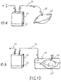
- a schematic of this method is depicted in FIG. 10-A .
- the sampling method includes a bag 40, a pump 50 powered by a battery 52, and tubing 44 connecting pump 50 to bag 40.
- Typical personal sampling pumps are suitable for this sampling method.
- Bags may be used for preparing standard fluid mixtures or for sampling.
- first the bag is filled with an appropriate measured volume of carrier fluid.
- the clean carrier gas is dosed with a quantity of fluid, typically, added by pump or syringe as shown in FIG. 10-A .
- a sample of an environment is delivered through the pump and tubing into the bag.
- the bag is then sealed and sent to a laboratory for analysis.
- the disadvantages include the cost, inaccuracy, and potential contamination from using an external pump to deliver and withdraw the fluid mix.
- the contamination or inaccuracy can occur from sorption and desorption of some chemicals or components of gas mixture or sample on the walls of the tubes, internal part of the pumps, filters, tubing and connectors.
- the same problem is caused by sorption of chemical components on the walls of the sampling bag.
- Even with cleaned walls, active adsorbing sites on the walls can reduce the concentration of certain chemicals when the sample gas is subsequently removed and analyzed. This adsorption may decrease the recovery of certain chemical compounds up to 15%.
- the recovery rates of t his method can be improved with the use of expensive stationary pumps and connection tubes, especially for sampling of trace components.
- FIG. 10-B the flexible sampling bag 40 is hermetically sealed within an outer container 60 with rigid walls.
- the air from the outer container is evacuated through tubing 44 by a pump 50.
- the pump may be powered by battery 52.
- the pressure in the outer container 60 is reduced and bag 40 expands and air from the surrounding environment enters the bag 40.
- the vacuum outside of the bag 40 and within the container 60 is a driving force for fluid sampling.
- the inlet of a sampling bag is connected directly with the ambient fluid. This method does not suffer from one of the major drawbacks of the configuration shown in FIG. 10-A .
- FIG. 10-B does not contact the pump 50 or tubing 44, therefore, there is no sorption or cross-contamination from the walls of the tubing 44, connectors, filter or parts of the sampling pump 50.
- the other drawbacks of the configuration of FIG. 10-A are, however, still persisting in the alternative configuration of FIG. 10-B , for example, the components is bulky and heavy; the equipment is expensive; the pump requires a battery and frequent maintenance; the sorption on the walls of the bag is the same as described above.
- U.S. Patent 3,866,474 to Hasselman describes a system in which a sample and an inert gas are drawn into a sample bag within a hermetically sealed container.
- U.S. Patent 3,965,946 to D'Alo describes improvements in the construction of the outer container.
- U.S. Patent 5,437,201 to Krueger describes a method of repeatedly purging the sampling bag within the outer container. More sophisticated devices are disclosed in U.S. Patent 5,714,696 to Yemans . The devices attempt to overcome the disadvantages of the system to obtain samples with very low contamination levels.
- U.S. Patent 6,338,282 to Gilbert describes an apparatus for collection of liquids proves the versatility of this approach. More recently U.S. Patent 6,993,985 to Srebro describes using the apparatus combined in single device yet connected to external vacuum source. Despite of cleanliness suggested by this method, it is using comparably heavy, bulky and expensive equipment requiring calibration and battery maintenance.
- U.S. Patent 4,546,659 to Gill et al. discloses a small (10 ml) envelope for the collection of atmospheric air samples for subsequent analysis.
- the envelope is formed of first and second opposed panels of flexible, gas impermeable material which are peripherally sealed to define a collection chamber.
- the envelope contains expandable means such as a spiral spring or foam.
- the expandable means transfer force to the walls via guard plate and large septum.
- a device that allows use of sampling bags without external hand or electric pumps and without connecting tubes.
- a device capable of fast grab sampling and fast consecutive strokes/flushes of the sampling bag, thereby to allow sorption equilibrium on the bag's walls.
- a device that simplifies sampling such that personnel with minimal training may properly use and perform industrial hygiene sampling.
- such a device that is inexpensive, easy to manufacture, designed for multiple use, may be used with both sampling bags specially designed and conventional sampling bags, light, not bulky, hand or self operated and easy to transport, and/or intrinsically safe in use.
- JP S55 63736 A , JP S52 18390 A and JP S52 10191 A disclose gas sampling devices.
- Embodiments of the present invention as defined in claim 1 are directed to a device for filling and emptying sampling bags.
- Embodiments of the device comprise mechanical means to expand the sampling bag thereby creating a reduced pressure inside the sampling bag relative to the environment to be sampled. The expansion of the sampling bag creates the driving force for a fluid to be sampled to fill the bag.
- Embodiments of the device may utilize conventional sampling bags or sampling bags specially designed for embodiments of the device.
- Embodiments of the device allowing relatively fast grab sampling and convenient flushing for achieving on-the-wall equilibrium of the sampled air contaminant.
- Further embodiments of the device may be used with sampling bags for a sampling system which permits sampling without any additional devices such as pumps and tubing.
- the device comprise flaps capable of being folded to form a box for storage, shipping and/or transportation of the sampled bag. Further embodiments of the device may be used for self sampling.
- an embodiment of the sampling device is intended for the same uses as conventional market available sampling bags.
- Embodiments of the device comprise two surfaces. Each surface of the device may be attached to opposite sides of a sampling bag.
- the sampling device comprises substantially rectangular hinged panels, wherein each panel has an inner surface capable of adhering, attaching or otherwise connecting to one side of sampling bag's outer surface.
- the inner surface of the panel is removably adhered to the walls of the sampling bag, however, in certain other embodiments the sampling device may be integral or incorporated directly into the sampling bag.
- the two opposite side walls of the sampling bag are temporarily engaged with means of engagement mounted on the panels of the clamp.
- the clamps When the clamps are closed, the bag is squeezed substantially to zero volume and, when the clamps are opened, the walls are pulled apart creating a moderate underpressure or a vacuum within the sampling bag. If the sampling bag is opened to the atmosphere, the expansion of the sampling bag allows air to be drawn into the inner space of the sample bag.
- the panels may have handles; for convenience.
- the sampling device comprises two panels, wherein the inner surfaces of the panels are hinged such that the inner surfaces are substantially parallel or close to parallel during the sampling.
- a parallel relationship will allow maximum expansion of a typical conventional sampling bag, however, embodiments of the sampling device may comprise panels with inner surfaces that are not parallel during sampling or embodiments of the sampling device may comprise panels that are only parallel when the device is in the closed position to facilitate evacuation of the sample bag.
- the walls of the sampling bag may be sufficiently adhered, attached, or otherwise connected to the panels of the sampling device such that biasing the panels away from each other causes the sampling bag to inflate during the sampling process.
- the adhering forces between the panels and bag's walls should to be stronger than the opposing force that are created by the reduction of pressure with the sampling bag.
- the reduction in pressure will depend upon various forces including, but not limited to, the size of the inlet, the density of the fluid, the force applied to the panels, for example.
- the operator can control the pulling forces and/or speed on the clamp panels in order to perform sampling and keeping the bag walls attached to the clamp panels during sampling.
- the adhering forces between the panels and bag's walls may be provided by one of the following means:
- the sampling device may comprise substantially rigid panels.
- substantially rigid means that the panels may be pulled apart to without sufficient deflation to inflate a sampling bag and pushed together to substantially empty the sampling bag.
- sampling device comprises a sampling bag with at least one slot or channel incorporated into or on the flexible walls of the sampling bag for mechanically attaching the sampling device to the sampling bag.
- the sampling device may comprise at least one tab or tine for inserting into the slot or channel of the sampling bag.
- the sampling device may comprise adhesive patches or labels that comprise at least one slot or channel. The adhesive patch or label may then be attached to a sampling bag thus providing at least one slot or channel on the sampling bag for connecting to the sampling device.
- the patch or label may comprise a corrugated portion a patch or label may then be adhered on each side of the sampling bag.
- the corrugated portion defines channels and the sampling device may comprise a series of tines with similar pitch or spacing between teeth to correspond with the corrugation.
- the teeth of the fork may engage the corrugated patches or label and transfer pulling or inflating forces to the bag's walls when panels are biased apart.
- Embodiments of the sampling device may also be configured as a self sampling device.
- Embodiments of the self-sampling device comprise means for biasing the walls of sampling bag.
- an embodiment of the self sampling device may comprise two rectangular panels with accurate shape.
- the panels when placed adjacent to each other may substantially resemble the wall of a cylinder.
- the two panels may be in any shape that may be pushed together to be in a substantially parallel position, then the means for biasing may open and inflate the sampling bag.
- the panels of the self sampling device comprise a material with shape memory to bias the sampling bag walls apart.
- the self sampling device may comprise flat panels and a spring, coil spring, leaf spring, pneumatic cylinders, or other biasing means for exerting springing forces to bias the panels away from each other.
- the sampling device may comprise two panels in hinged connection on one end.
- the other end of the panels may be hinged, not hinged, connected or may be unconnected.
- a cross-section of such an embodiment may resemble a substantially circular or oval shape or semi circular or semi oval shape.
- at least a central portion of the panels has a means for temporary engagement of the bag's side walls. When a force is applied, the two panels are pressed close to each other toward a substantially flat shape. After removing the force, the biasing means, elastic forces or shape memory of the panels tend to return the panels to their original cross-sectional shape. Once the walls of the sampling bag are pressed together by a biasing force on to the panels, the panels will then bias the bag's walls apart creating moderate underpressure and, thereby, creating sufficient driving force for fluid to enter the bag.
- the surface area of the panels when pressed together is sufficiently larger than the outer surface area of the sampling bag.
- one end of the panels may be made detachably hinged to the other panel allowing the bag to be removed after being loaded with sampled fluid.
- Another embodiment of the self-sampling device may comprise spring biased panels that may be are connected on one side with a hinge and the other side capable of being separated by a biasing force, such as by a biasing means, as described, or by hand.
- devices may comprise two panels having two opposite sides connected by hinges or a combination such one side comprising a hinge and the other side comprising a spring, or both sides comprising a spring.
- An embodiment of the sampling device comprising hinged panels, an inlet port and a biasing means for self sampling may be further envisioned as long term sampling system.
- the inlet port may be designed or have connected to the inlet port a controllable aerodynamic resistance tube or restriction.
- the maximum flow rate drawn into the bag may be a controlled and a reliable, substantially repeatable volume may be drawn over a sampling period to provide reproducible sampling.
- sampling device comprises a sampling bag having permanently mounted panels of a semi-rigid material on both sides.
- shape of the panels is substantially rectangular (though the panels may be any shape) and their size may slightly bigger than the size of flattened bag (though the panels may be any size that is capable of inflating and substantially deflating the sample bag).
- each of the panels is permanently adhered to the flexible sampling bag's sides with an appropriate adhesive.
- the size of the adhered spot may be approximately 1/3 of the surface area one bag wall but may vary as desired.
- the panels may comprise means for biasing the panels away from each other, handles of soft material and/or may have precut foldable and retractable handles.
- the panels further comprise foldable extensions capable of forming a box construction. The extensions may be folded to form a box to allow convenient storage, transportation and/or mailing of the bag. The extensions may carry strips of adhesive material construction capable of stabilizing the box.
- Embodiments of the sampling device comprise two panels capable of assisting with inflating and deflating the sampling or other bag.
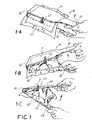
- the sampling device 10 comprises an top panel 11 and a bottom panel 13.
- the top panel 11 and bottom panel 13 have a substantially rectangular shape and area sufficient to cover a substantial portion of the surface of the sampling bag 40.
- the top panel 11 and bottom panel 13 have one of their ends rotatably attached with a hinged connection 16.
- the other ends of the top panel 11 and bottom panel 13 are shaped as handles 19 for easy operation by hands.
- Other embodiments of the sampling device may comprise panels having other handle designs.
- the inner surface of the rotatably connected top panel 11 and bottom panel 13 at least partially comprises an adhering means 30 capable of at least temporary adhesion to one surface of the sampling bag 40.
- the material for adhering means 30 may be selected from one of the group including, but not limited to; a permanent adhesive, a temporary adhesive, a multitude of mini vacuuming cups suction capable do adhering to material with smooth surface such as sampling bag 40 wall surface and attached to the panels; a flat magnetic material mounted on top panel 11 and bottom panel 13 and on both side walls of the sampling bag 40, as well as other adhesives or connectors or combinations of such adhesives and connectors.
- the shape and the size of panels of embodiments of the sampling device may be any shapes and/or sizes desirable to match or conform to the shape and size of a sampling bag.
- the surface area of the panels 11 and 13 may be slightly larger than the surface area of the sampling bag.
- the panel may or many not correspond with the contour of the sampling bias bag, nevertheless in examples not according to the invention a panel with a smaller surface than the sampling bag may also be used, for example, the panels may be smaller if the bag is previously flattened by vacuuming or folding the sampling bag or if the sampling bag has sufficiently stiff or rigid walls.
- the volume of a fully or substantially deflated sampling bag is less than 5% of the fully inflated volume. This remaining volume is substantially negligible once the bag is clean, sufficiently purged, or pre-cleaned before use (as in standard sampling procedure for reuse of sampling bags).
- the positioning of the adhering means in the example not according to the invention of FIG. 1 is a contacting line.
- the adhering means of this embodiment takes much less area of the panels compared to the total panel surface and the sampling bag surface because in the inflated/loaded position the contact area between the bag 40 and the top panel 11 and bottom panel13 is smaller than in the flattened position. In a general case, this area may be in the range of approximately 1/3 from the total area of the side wall of the flattened sampling bag 40 , for example.
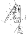
- Sampling device 10 Of FIG. 2 comprises an additional connecting plate 18 with a hinged connection 17 to the top panel 11 in order to stay somewhat parallel to the bottom panel 13 .
- a sampling device with a hinged connection 17 may result in more complete loading and/or unloading of the sampling bag 40 .
- the contacting surfaces on the top additional plate 18 as well as bottom panel 13 comprise an adhering means.
- the embodiments of the sampling device shown in FIGS.1 and 2 may be used with conventional or standard sampling bags or specially designed sampling bags.
- Embodiments of the sampling device may comprise removable and/or changeable panels or a set of removable and/or changeable panels.
- the panels in the set may be of different size, shape, or include a different adhesive.
- an embodiment may include a kit of multiple sized panels so the panel may be changed to be more compatible with the size of the desired sampling bag.
- a smaller panel may be removed and replaced with a panel comprising a larger surface area than the surface area of the sampling bags flexible wall.
- the examples not according to the invention shown on FIG.1 and 2 may be moved away from each other not only by the hands of operator but by other biasing means such as, (but not limited to weights, springs, an electric motor, or other biasing mechanisms as described).
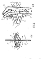
- FIG.3 another example of a non-claimed sampling device is shown.
- the sampling device 10 of FIG. 3 comprises two panels-top panel12 and bottom panel14 made from a flexible material with shape memory.
- Embodiments of the invention may have a cross-sectional shape in the general shape of a cylinder, oval, a portion of a circle, or a portion of an oval.
- the flexible material for those panels may be selected from a group including, but not limited to plastics, polycarbonates, nylon, polyester, multilayer composite plastics, metals, aluminum, stainless steel alloys, steel alloys, brass and bronze alloys.
- the top panel 12 and bottom panel 14 may have one or two sides pivotally connected.
- the sampling device comprise a panel having one end pivotally connected to the panel and the other end of the panel comprising a releasably hinged connection.
- the releasable hinged connection may comprise a pin that may be inserted to make the hinged connection and removed to release the hinged connection.
- both ends of top panel 12 and bottom panel 14 may be unconnected or comprise a hinged releasable connection.
- Each top panel 12 and bottom 14 may be connected to the sample bag as the already discussed with embodiments shown in FIGS. 1 and 2 .
- the sampling bag 40 of FIG. 3 may be flattened in the cavity formed between top panel 12 and bottom panel 14 when the panels are forced by hands or other biasing force to be substantially flat.
- the force may be used to simultaneously connect the sampling bag to the top panel 12 and/or the bottom panel 14 adhering means 30 and compress, deflate or flatten the sampling bag.
- the inlet cap or sampling valve 60 FIG. 3 -B
- the external force is removed.
- the elastic, or shape memory, or other biasing forces on the panels pull the sampling bag walls into an inflated or open position. These biasing forces create initially a small space with underpressure.
- This underpressure relative to the environment is the driving force for the fluid to pass through the inlet or valve 60 and begin to inflate the bag.
- the top panel and bottom panels continue to move apart and then stops as the bag is filled.
- the volume of the sampling bag may be limited by a mechanical stop such as a plastic strip or similar stop, the fully separated position of the shape memory panels 12 and 14 , the length or shape of the biasing means, or other mechanical limitation of the sampling bag or sampling device.
- the device thus provides a self sampling device that may be filled over an extended period or cycle and the sampling time for this cycle is limited mainly by the biasing forces and the aerodynamic resistance and/or flow of fluid through the inlet port or valve 60 .
- the sampling time may varied between short sampling periods to long sampling periods.
- the sampling time may be controlled by the biasing means of the panels and/or the sampling inlet or design of valve to vary from very short time, (grab sample) to 15 , 30 min, 1 hour, 8 hours, or days, or other desired sample time.
- the devices upon present invention are much lighter, simpler and less expensive.
- FIG 4-B An example not according to the invention is shown in FIG 4-B .
- This embodiment of the sampling device 40 comprises a top panel 34 that has a surface area that is smaller than the surface area of the wall of the sampling bag.
- the sampling device may have a panel 34 that is merely sufficient for attaching handle 19 to the sampling bag 40.
- the handle 19 may be directly attached to the sampling bag.
- the bags may be deflated by connecting inlet 60 to a vacuum source, for example. The bag may then be conveniently stored in a deflated state until needed. The sampling device may then be used to obtain a sample by simply opening inlet 60 and pulling the handle 19 or handles 19, if applicable.
- Such an embodiment gives the sampling bag unique properties to be stored in small space and when needed for sampling purposes may be easily used without any other apparatus and complicated system with tubing, etc.
- the panels 34 may be made from corrugated material having inside channels which may be engaged by forklike means as discussed per FIGS. 1 and 2 .
- a still further non-claimed example of a sampling device is shown in FIGS 5A to 7B .
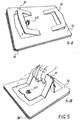
- the sampling bag may be flattened between the two panels 36 as shown on FIG.5-A .
- foldable handles are precut and can be easily moved up as shown on FIG.5-A and then engaged by hands as shown in FIG. 5-B .
- For grab sampling the inlet 60 may be completely opened and sampling bag 40 can be filled by pulling handles 19 until the bag is appropriately filled with the targeted fluid as shown on FIG.6- 6-A and 6-B .
- the handles 19 may be folded flat as shown on FIG.7-A and both sides can be pushed towards each other shown on FIG.7-B and edges fixed with tape, clips or other means to ease insertion in an envelope for storage or shipping.
- Embodiments of the sampling bag may include such panels incorporated directly into the walls of the sampling bag.
- the bag may be flushed several times in by inflating and deflating the sampling bag as shown on FIG. 8 until the inside volume is purged and the inside walls are substantially at equilibrium with the targeted substances in the sampled fluid. This will gives the sampling device the unique feature of achieving almost 100% recovery, compare to 85-90% with one only sampling suction from prior art devices.
- FIG. 9 An embodiment of the invention is depicted in FIG. 9 demonstrating the versatility of the concept allowing the extensions of side panels 36 to be used after sampling to form a rigid wall box convenient for prolonged storage or mailing of the sample.
- Embodiments of the devices discussed have many unique features as compared to conventional sampling bags and methods, embodiments of the sampling bag have some or all of the following features:
Landscapes
- Life Sciences & Earth Sciences (AREA)
- Health & Medical Sciences (AREA)
- Pathology (AREA)
- General Health & Medical Sciences (AREA)
- Immunology (AREA)
- Physics & Mathematics (AREA)
- Chemical & Material Sciences (AREA)
- Analytical Chemistry (AREA)
- Biochemistry (AREA)
- General Physics & Mathematics (AREA)
- Hydrology & Water Resources (AREA)
- Biomedical Technology (AREA)
- Molecular Biology (AREA)
- Engineering & Computer Science (AREA)
- Sampling And Sample Adjustment (AREA)
- Bag Frames (AREA)
Claims (13)
- Probenahmevorrichtung (10), die Folgendes umfasst:einen Probenahmebeutel (40), der zwei biegsame Wände und ein Innenvolumen umfasst;zwei im Wesentlichen starre Platten (11, 13);Mittel zum Ankleben der Wände des Probenahmebeutels an die Platten, wobei jede biegsame Wand des Probenahmebeutels eine Außenoberfläche aufweist und jede der im Wesentlichen starren Platten derart einen Oberflächeninhalt aufweist, der größer als der Außenoberflächeninhalt der biegsamen Wand ist, dass die zwei im Wesentlichen starren Platten miteinander vorgespannt werden können, um das Innenvolumen auf ein Volumen von weniger als 5 % des vollständig aufgeblasenen Volumens des Probenahmebeutels zu reduzieren;wobei der Probenahmebeutel ferner eine Einlassöffnung (60) umfasst, die durch eine der zwei biegsamen Wände definiert ist, die eine Kommunikation zwischen einem Umgebungsfluid, das zu beproben ist, und dem internen Probenahmevolumen bereitstellt; undwobei die zwei im Wesentlichen starren Platten eine obere im Wesentlichen starre Platte (11), die mit einer der biegsamen Wände auf einer ersten Seite des Probennahmebeutels verbunden ist, und eine untere im Wesentlichen starre Platte (13) umfasst, die mit der anderen der biegsamen Wände auf einer Seite verbunden ist, die gegenüber der ersten Seite des Probenbeutels ist, wobei die Platten Klappen (36) umfassen, wobei die Klappen konfiguriert sind, um gefaltet zu werden, um eine Schachtel um den Probenahmebeutel herum auszubilden.
- Probenahmevorrichtung nach Anspruch 1, wobei die starren Platten an einem Ende in einer gelenkigen Anordnung miteinander verbunden sind.
- Probenahmevorrichtung nach einem der Ansprüche 1 oder 2, wobei die Mittel zum Ankleben Mittel zum lösbaren Ankleben sind.
- Probenahmevorrichtung nach Anspruch 3, wobei das Mittel zum lösbaren Ankleben ein beliebiges Mittel zum ausreichenden Ankleben des Probenahmebeutels an der Oberfläche der Platte ist, um die Wände des Beutels angeklebt zu halten, um genügend bewegende Kraft zu erzeugen, um Luft in den Beutel zu treiben, wenn die Platten wegbewegt werden.
- Probenahmevorrichtung nach Anspruch 3, wobei das Mittel zum lösbaren Ankleben aus der Gruppe ausgewählt ist, die aus Folgenden besteht: temporären Klebepunkten, die an einem Teil der gegenüberliegenden Wände des Probenahmebeutels haften; Mini-Vakuumsaugnäpfen, die an den Innenoberflächen der Platten gelegen sind; klettverschlussartigen Haftetiketten, die dauerhaft an der Innenoberfläche der Platten befestigt sind und entweder temporär oder dauerhaft an den Wänden des Beutels angeklebt sind; Klebesprays; wasserlöslichen Klebstoffen, wie etwa, aber nicht beschränkt auf, thermoplastische wasserlösliche Klebstoffe; druckempfindlichen Klebstoffen; magnetischen Flachmaterialien wie etwa, aber nicht beschränkt auf Magnetfolien; Doppelklebebändern; anderen lösbaren chemischen oder mechanischen Klebstoffen; oder Kombinationen von diesen.
- Probenahmevorrichtung nach einem der vorhergehenden Ansprüche, wobei wenigstens eine Platte einen Griff (19) umfasst.
- Probenahmevorrichtung nach Anspruch 1, wobei die Probenahmevorrichtung ferner Vorspannmittel zum Ausüben von Federkräften auf die Platten umfasst, um die Platten voneinander weg vorzuspannen.
- Probenahmevorrichtung nach Anspruch 7, wobei das Vorspannmittel eine Feder, eine Schraubenfeder, eine Blattfeder oder ein Pneumatikzylinder ist.
- Probenahmevorrichtung nach Anspruch 7, wobei die obere im Wesentlichen starre Platte und die untere im Wesentlichen starre Platte an einem Ende mit einer gelenkigen Anordnung drehbar befestigt sind.
- Probenahmevorrichtung nach Anspruch 7, wobei die obere im Wesentlichen starre Platte in Richtung der unteren im Wesentlichen starren Platte vorgespannt sein kann, um das interne Probenahmevolumen auf ein Volumen von weniger als 5 % des vollständig aufgeblasenen Volumens zu reduzieren.
- Probenahmevorrichtung nach Anspruch 1, wobei die Schachtel eine Versandschachtel ist.
- Probenahmevorrichtung nach Anspruch 1, wobei die Klappen Streifen aus Klebematerial umfassen, die konfiguriert sind, um die Schachtel zu stabilisieren.
- Probenahmevorrichtung nach Anspruch 1, wobei jede der Platten einen einziehbaren Griff (19) umfasst, der faltbar ist.
Applications Claiming Priority (2)
| Application Number | Priority Date | Filing Date | Title |
|---|---|---|---|
| US30500110P | 2010-02-16 | 2010-02-16 | |
| PCT/US2011/025071 WO2011103181A1 (en) | 2010-02-16 | 2011-02-16 | Device for fluid sampling |
Publications (3)
| Publication Number | Publication Date |
|---|---|
| EP2536641A1 EP2536641A1 (de) | 2012-12-26 |
| EP2536641A4 EP2536641A4 (de) | 2018-03-07 |
| EP2536641B1 true EP2536641B1 (de) | 2021-08-11 |
Family
ID=44368688
Family Applications (1)
| Application Number | Title | Priority Date | Filing Date |
|---|---|---|---|
| EP11745169.0A Active EP2536641B1 (de) | 2010-02-16 | 2011-02-16 | Vorrichtung zur flüssigkeitsprobennahme |
Country Status (8)
| Country | Link |
|---|---|
| US (2) | US8714035B2 (de) |
| EP (1) | EP2536641B1 (de) |
| JP (1) | JP6113506B2 (de) |
| CN (1) | CN102883968B (de) |
| BR (1) | BR112012020421A2 (de) |
| CA (1) | CA2790125C (de) |
| MX (1) | MX342179B (de) |
| WO (1) | WO2011103181A1 (de) |
Families Citing this family (28)
| Publication number | Priority date | Publication date | Assignee | Title |
|---|---|---|---|---|
| CN102883968B (zh) * | 2010-02-16 | 2015-05-13 | 耐斯特科技有限公司 | 用于流体取样的装置 |
| WO2013102032A1 (en) * | 2011-12-28 | 2013-07-04 | Nexxteq Llc | Sample bag with multilayer walls |
| US9188509B2 (en) | 2011-12-28 | 2015-11-17 | Nextteq Llc | Sampling device |
| JP6623179B2 (ja) | 2014-06-02 | 2019-12-18 | ネクストテック エルエルシー | サンプリング装置のためのフロータイマー |
| CN104535377B (zh) * | 2014-12-04 | 2017-02-22 | 苏州国环环境检测有限公司 | 气体采样装置 |
| US9833284B2 (en) * | 2015-02-04 | 2017-12-05 | Biosense Webster (Israel) Ltd. | Pressure-driven irrigation pump |
| CN108351278A (zh) * | 2015-06-05 | 2018-07-31 | 威廉·T·韦切雷 | 低渗透率样品袋 |
| CN105067391A (zh) * | 2015-07-16 | 2015-11-18 | 苏州华达仪器设备有限公司 | 一种方便携带的空气快速取样袋 |
| CN105865857A (zh) * | 2016-04-06 | 2016-08-17 | 易安蓝焰煤与煤层气共采技术有限责任公司 | 化学能气体收集-输出技术方法与装置 |
| CN108279300A (zh) * | 2017-05-08 | 2018-07-13 | 许昌义 | 酒驾检测机 |
| CN109323893A (zh) * | 2018-09-28 | 2019-02-12 | 暨南大学 | 适用于无人机或系留汽艇的气溶胶采样袋、装置及方法 |
| US10634558B1 (en) | 2018-11-13 | 2020-04-28 | Anna Ailene Scott | Air quality monitoring system and enhanced spectrophotometric chemical sensor |
| CN109520782A (zh) * | 2018-12-10 | 2019-03-26 | 黔西县黔希煤化工投资有限责任公司 | 一种真空法在分析取样中的应用 |
| US10697947B1 (en) | 2019-01-23 | 2020-06-30 | Project Canary, Inc. | Apparatus and methods for reducing fugitive gas emissions at oil facilities |
| WO2020243221A1 (en) * | 2019-05-31 | 2020-12-03 | Dow Global Technologies Llc | Flexible container with tether |
| US11150167B1 (en) | 2020-04-03 | 2021-10-19 | Project Canary, Pbc | Air sampling actuator and associated method |
| WO2022056152A1 (en) | 2020-09-10 | 2022-03-17 | Project Canary, Pbc | Air quality monitoring system and method |
| CN112255048B (zh) * | 2020-11-17 | 2023-12-01 | 佳木斯大学 | 一种基础医学用检验取样装置 |
| CN112961763B (zh) * | 2021-02-05 | 2024-01-09 | 重庆三峡学院 | 一种微生物定期检测用的取样装置 |
| US12029377B2 (en) * | 2021-07-08 | 2024-07-09 | ZHF Group, LLC | Vacuum bag |
| US11598698B1 (en) * | 2021-09-08 | 2023-03-07 | Robert Laughlin | Air testing collector |
| CN114279776A (zh) * | 2021-12-23 | 2022-04-05 | 深圳市步锐生物科技有限公司 | 手动收集环境背景气的气袋装置及其制备方法与使用方法 |
| CN114516482A (zh) * | 2021-12-27 | 2022-05-20 | 上海交通大学 | 一种热敏螺旋弹簧在柔性填充容器中的应用 |
| US11802860B1 (en) | 2022-03-25 | 2023-10-31 | Project Canary, Pbc | Emissions detection system and methods |
| US11887203B1 (en) | 2023-02-01 | 2024-01-30 | Project Canary, Pbc | Air quality monitors minimization system and methods |
| US11861753B1 (en) | 2023-02-01 | 2024-01-02 | Project Canary, Pbc | Air quality monitors minimization system and methods |
| US11727519B1 (en) | 2023-02-01 | 2023-08-15 | Project Canary, Pbc | Air quality monitors minimization system and methods |
| USD1102911S1 (en) * | 2024-05-20 | 2025-11-25 | Nasco Sampling Llc | Sampling and pour bag |
Family Cites Families (39)
| Publication number | Priority date | Publication date | Assignee | Title |
|---|---|---|---|---|
| US3239312A (en) * | 1962-03-02 | 1966-03-08 | Coleman Instr Corp | System for processing and analysis of liquid samples |
| US3206982A (en) * | 1962-12-18 | 1965-09-21 | Beckman Instruments Inc | Fluid sampling device |
| US3512700A (en) * | 1968-10-30 | 1970-05-19 | Jaite Display Bag Co The | Flexible bag construction |
| JPS5232639B2 (de) | 1972-12-28 | 1977-08-23 | ||
| JPS513283A (ja) | 1974-06-26 | 1976-01-12 | Hitachi Ltd | Henkakusokuteisochi |
| JPS5113670A (en) | 1974-07-25 | 1976-02-03 | Iseki Agricult Mach | Konbainni okeru shorizumikokukanno ketsusokuhoshutsusochi |
| JPS555954Y2 (de) * | 1974-07-29 | 1980-02-12 | ||
| JPS5210191A (en) * | 1975-07-15 | 1977-01-26 | Yukie Chiba | Sample gas collecting bag |
| JPS5218390A (en) * | 1975-08-01 | 1977-02-10 | Osaka Kagaku Bunseki Center:Kk | Method of smpling gas for analysis |
| JPS5295485U (de) * | 1976-01-16 | 1977-07-16 | ||
| JPS52106190U (de) * | 1976-02-10 | 1977-08-12 | ||
| JPS53138332A (en) | 1977-05-07 | 1978-12-02 | Canon Inc | Cine camera |
| JPS5553446U (de) * | 1978-10-06 | 1980-04-10 | ||
| JPS6059536B2 (ja) * | 1978-11-09 | 1985-12-25 | 宇部興産株式会社 | 大気サンプル捕集方法および装置 |
| JPS5673298A (en) * | 1979-11-17 | 1981-06-17 | Toyota Central Res & Dev Lab Inc | Gas collector |
| JPS62181391A (ja) | 1986-08-29 | 1987-08-08 | Toa Nenryo Kogyo Kk | 光学的異方性炭素質ピツチの製造法 |
| JPH0185243U (de) * | 1987-11-27 | 1989-06-06 | ||
| CN2059904U (zh) * | 1990-02-15 | 1990-08-01 | 任乾健 | 折叠充气救生包 |
| US5180229A (en) * | 1991-03-08 | 1993-01-19 | Nasco International, Inc. | Sampling bag with enclosed wire ends |
| GB9212032D0 (en) * | 1992-06-05 | 1992-07-15 | Farrell Peter J | Collapsible container apparatus for fluid material |
| JPH087116B2 (ja) * | 1993-09-08 | 1996-01-29 | 海洋科学技術センター | 自動採水器 |
| US5853247A (en) * | 1997-05-27 | 1998-12-29 | Shroyer; John Bruce | Sample bag container |
| FR2791645B1 (fr) * | 1999-04-02 | 2001-06-15 | Valois Sa | Echantillon de produit fluide destine a la presse |
| US6734401B2 (en) * | 2000-06-28 | 2004-05-11 | 3M Innovative Properties Company | Enhanced sample processing devices, systems and methods |
| US6550967B2 (en) * | 2001-01-24 | 2003-04-22 | Barclay Brown Corp. | Bag stuffer |
| JP2004045398A (ja) | 2002-06-03 | 2004-02-12 | Straughan Technical Distribution Llc | 気体検出装置および一体型温度補正デバイスを使用する方法 |
| CA2501825C (en) * | 2002-10-09 | 2009-12-01 | Therasense, Inc. | Fluid delivery device, system and method |
| JP2004357918A (ja) * | 2003-06-04 | 2004-12-24 | Yokohama Rubber Co Ltd:The | 携帯用蘇生器 |
| GB0400632D0 (en) * | 2004-01-13 | 2004-02-11 | Scott Wilson Pavement Engineer | Improvements relating to the testing of mechanical properties of materials |
| US7690275B1 (en) * | 2004-08-26 | 2010-04-06 | Elemental Scientific, Inc. | Automated sampling device |
| CN2754648Y (zh) * | 2004-11-08 | 2006-02-01 | 张允芝 | 氧气袋 |
| US8042702B2 (en) * | 2007-06-05 | 2011-10-25 | GM Global Technology Operations LLC | Reconfigurable container and methods of fabrication and use thereof |
| CN201168306Y (zh) * | 2008-03-07 | 2008-12-24 | 徐瑞华 | 氧气袋加压装置 |
| CN201244266Y (zh) * | 2008-09-08 | 2009-05-27 | 马振广 | 新型氧气袋 |
| EP2258418A1 (de) * | 2009-06-05 | 2010-12-08 | Fresenius Medical Care Deutschland GmbH | Vorrichtung zur Probensammlung |
| CN102883968B (zh) * | 2010-02-16 | 2015-05-13 | 耐斯特科技有限公司 | 用于流体取样的装置 |
| CA2790016C (en) * | 2010-02-16 | 2018-12-11 | Nextteq, Llc | Containers for fluids with composite agile walls |
| FR2958401A1 (fr) * | 2010-04-01 | 2011-10-07 | Braun Medical Sas | Dispositif de prelevement d'un echantillon de liquide d'une poche souple |
| GB2494721B8 (en) * | 2011-11-15 | 2023-07-26 | Hermes Solution Ltd | Modular walling solution |
-
2011
- 2011-02-16 CN CN201180009817.XA patent/CN102883968B/zh not_active Expired - Fee Related
- 2011-02-16 US US13/028,587 patent/US8714035B2/en active Active
- 2011-02-16 WO PCT/US2011/025071 patent/WO2011103181A1/en not_active Ceased
- 2011-02-16 MX MX2012009534A patent/MX342179B/es active IP Right Grant
- 2011-02-16 EP EP11745169.0A patent/EP2536641B1/de active Active
- 2011-02-16 BR BR112012020421A patent/BR112012020421A2/pt not_active IP Right Cessation
- 2011-02-16 JP JP2012553995A patent/JP6113506B2/ja active Active
- 2011-02-16 CA CA2790125A patent/CA2790125C/en active Active
-
2014
- 2014-02-19 US US14/184,198 patent/US9574975B2/en active Active
Non-Patent Citations (1)
| Title |
|---|
| None * |
Also Published As
| Publication number | Publication date |
|---|---|
| EP2536641A4 (de) | 2018-03-07 |
| US20110197687A1 (en) | 2011-08-18 |
| HK1181012A1 (en) | 2013-11-01 |
| MX342179B (es) | 2016-09-20 |
| CN102883968A (zh) | 2013-01-16 |
| CA2790125C (en) | 2019-04-02 |
| US9574975B2 (en) | 2017-02-21 |
| WO2011103181A1 (en) | 2011-08-25 |
| CA2790125A1 (en) | 2011-08-25 |
| CN102883968B (zh) | 2015-05-13 |
| US20140318280A1 (en) | 2014-10-30 |
| JP2013519903A (ja) | 2013-05-30 |
| JP6113506B2 (ja) | 2017-04-12 |
| US8714035B2 (en) | 2014-05-06 |
| BR112012020421A2 (pt) | 2016-05-17 |
| EP2536641A1 (de) | 2012-12-26 |
| MX2012009534A (es) | 2013-02-21 |
Similar Documents
| Publication | Publication Date | Title |
|---|---|---|
| EP2536641B1 (de) | Vorrichtung zur flüssigkeitsprobennahme | |
| US9846108B2 (en) | Containers for fluids with composite agile walls | |
| US20110219891A1 (en) | Container For Fluid Sampling With Flexible Metal Alloy Walls | |
| US10359341B2 (en) | Sampling device | |
| US7870708B2 (en) | Device and method for evacuating a storage bag | |
| JPH09207909A (ja) | 急速減圧装置 | |
| HK1181012B (en) | Device for fluid sampling | |
| CA2858274C (en) | Sampling device | |
| HK1181013B (en) | Containers for fluids with composite agile walls | |
| CN116767683B (zh) | 一种猪链球菌2型基因检测试剂盒及其应用 | |
| HK1181014A (en) | Container for fluid sampling with flexible metal alloy walls | |
| WO2011097298A1 (en) | Bag vacuum apparatus |
Legal Events
| Date | Code | Title | Description |
|---|---|---|---|
| PUAI | Public reference made under article 153(3) epc to a published international application that has entered the european phase |
Free format text: ORIGINAL CODE: 0009012 |
|
| 17P | Request for examination filed |
Effective date: 20120913 |
|
| AK | Designated contracting states |
Kind code of ref document: A1 Designated state(s): AL AT BE BG CH CY CZ DE DK EE ES FI FR GB GR HR HU IE IS IT LI LT LU LV MC MK MT NL NO PL PT RO RS SE SI SK SM TR |
|
| DAX | Request for extension of the european patent (deleted) | ||
| RIC1 | Information provided on ipc code assigned before grant |
Ipc: B65D 33/02 20060101AFI20171016BHEP |
|
| RA4 | Supplementary search report drawn up and despatched (corrected) |
Effective date: 20180207 |
|
| RIC1 | Information provided on ipc code assigned before grant |
Ipc: B65D 33/02 20060101AFI20180201BHEP |
|
| STAA | Information on the status of an ep patent application or granted ep patent |
Free format text: STATUS: EXAMINATION IS IN PROGRESS |
|
| 17Q | First examination report despatched |
Effective date: 20200417 |
|
| GRAP | Despatch of communication of intention to grant a patent |
Free format text: ORIGINAL CODE: EPIDOSNIGR1 |
|
| STAA | Information on the status of an ep patent application or granted ep patent |
Free format text: STATUS: GRANT OF PATENT IS INTENDED |
|
| INTG | Intention to grant announced |
Effective date: 20210310 |
|
| GRAS | Grant fee paid |
Free format text: ORIGINAL CODE: EPIDOSNIGR3 |
|
| GRAA | (expected) grant |
Free format text: ORIGINAL CODE: 0009210 |
|
| STAA | Information on the status of an ep patent application or granted ep patent |
Free format text: STATUS: THE PATENT HAS BEEN GRANTED |
|
| AK | Designated contracting states |
Kind code of ref document: B1 Designated state(s): AL AT BE BG CH CY CZ DE DK EE ES FI FR GB GR HR HU IE IS IT LI LT LU LV MC MK MT NL NO PL PT RO RS SE SI SK SM TR |
|
| REG | Reference to a national code |
Ref country code: GB Ref legal event code: FG4D |
|
| REG | Reference to a national code |
Ref country code: CH Ref legal event code: EP |
|
| REG | Reference to a national code |
Ref country code: DE Ref legal event code: R096 Ref document number: 602011071538 Country of ref document: DE |
|
| REG | Reference to a national code |
Ref country code: AT Ref legal event code: REF Ref document number: 1419181 Country of ref document: AT Kind code of ref document: T Effective date: 20210915 Ref country code: IE Ref legal event code: FG4D |
|
| REG | Reference to a national code |
Ref country code: SE Ref legal event code: TRGR |
|
| REG | Reference to a national code |
Ref country code: LT Ref legal event code: MG9D |
|
| REG | Reference to a national code |
Ref country code: NL Ref legal event code: MP Effective date: 20210811 |
|
| REG | Reference to a national code |
Ref country code: AT Ref legal event code: MK05 Ref document number: 1419181 Country of ref document: AT Kind code of ref document: T Effective date: 20210811 |
|
| PG25 | Lapsed in a contracting state [announced via postgrant information from national office to epo] |
Ref country code: ES Free format text: LAPSE BECAUSE OF FAILURE TO SUBMIT A TRANSLATION OF THE DESCRIPTION OR TO PAY THE FEE WITHIN THE PRESCRIBED TIME-LIMIT Effective date: 20210811 Ref country code: FI Free format text: LAPSE BECAUSE OF FAILURE TO SUBMIT A TRANSLATION OF THE DESCRIPTION OR TO PAY THE FEE WITHIN THE PRESCRIBED TIME-LIMIT Effective date: 20210811 Ref country code: NO Free format text: LAPSE BECAUSE OF FAILURE TO SUBMIT A TRANSLATION OF THE DESCRIPTION OR TO PAY THE FEE WITHIN THE PRESCRIBED TIME-LIMIT Effective date: 20211111 Ref country code: PT Free format text: LAPSE BECAUSE OF FAILURE TO SUBMIT A TRANSLATION OF THE DESCRIPTION OR TO PAY THE FEE WITHIN THE PRESCRIBED TIME-LIMIT Effective date: 20211213 Ref country code: RS Free format text: LAPSE BECAUSE OF FAILURE TO SUBMIT A TRANSLATION OF THE DESCRIPTION OR TO PAY THE FEE WITHIN THE PRESCRIBED TIME-LIMIT Effective date: 20210811 Ref country code: AT Free format text: LAPSE BECAUSE OF FAILURE TO SUBMIT A TRANSLATION OF THE DESCRIPTION OR TO PAY THE FEE WITHIN THE PRESCRIBED TIME-LIMIT Effective date: 20210811 Ref country code: BG Free format text: LAPSE BECAUSE OF FAILURE TO SUBMIT A TRANSLATION OF THE DESCRIPTION OR TO PAY THE FEE WITHIN THE PRESCRIBED TIME-LIMIT Effective date: 20211111 Ref country code: LT Free format text: LAPSE BECAUSE OF FAILURE TO SUBMIT A TRANSLATION OF THE DESCRIPTION OR TO PAY THE FEE WITHIN THE PRESCRIBED TIME-LIMIT Effective date: 20210811 Ref country code: HR Free format text: LAPSE BECAUSE OF FAILURE TO SUBMIT A TRANSLATION OF THE DESCRIPTION OR TO PAY THE FEE WITHIN THE PRESCRIBED TIME-LIMIT Effective date: 20210811 |
|
| PG25 | Lapsed in a contracting state [announced via postgrant information from national office to epo] |
Ref country code: PL Free format text: LAPSE BECAUSE OF FAILURE TO SUBMIT A TRANSLATION OF THE DESCRIPTION OR TO PAY THE FEE WITHIN THE PRESCRIBED TIME-LIMIT Effective date: 20210811 Ref country code: LV Free format text: LAPSE BECAUSE OF FAILURE TO SUBMIT A TRANSLATION OF THE DESCRIPTION OR TO PAY THE FEE WITHIN THE PRESCRIBED TIME-LIMIT Effective date: 20210811 Ref country code: GR Free format text: LAPSE BECAUSE OF FAILURE TO SUBMIT A TRANSLATION OF THE DESCRIPTION OR TO PAY THE FEE WITHIN THE PRESCRIBED TIME-LIMIT Effective date: 20211112 |
|
| PG25 | Lapsed in a contracting state [announced via postgrant information from national office to epo] |
Ref country code: NL Free format text: LAPSE BECAUSE OF FAILURE TO SUBMIT A TRANSLATION OF THE DESCRIPTION OR TO PAY THE FEE WITHIN THE PRESCRIBED TIME-LIMIT Effective date: 20210811 |
|
| PG25 | Lapsed in a contracting state [announced via postgrant information from national office to epo] |
Ref country code: DK Free format text: LAPSE BECAUSE OF FAILURE TO SUBMIT A TRANSLATION OF THE DESCRIPTION OR TO PAY THE FEE WITHIN THE PRESCRIBED TIME-LIMIT Effective date: 20210811 |
|
| REG | Reference to a national code |
Ref country code: DE Ref legal event code: R097 Ref document number: 602011071538 Country of ref document: DE |
|
| PG25 | Lapsed in a contracting state [announced via postgrant information from national office to epo] |
Ref country code: SM Free format text: LAPSE BECAUSE OF FAILURE TO SUBMIT A TRANSLATION OF THE DESCRIPTION OR TO PAY THE FEE WITHIN THE PRESCRIBED TIME-LIMIT Effective date: 20210811 Ref country code: SK Free format text: LAPSE BECAUSE OF FAILURE TO SUBMIT A TRANSLATION OF THE DESCRIPTION OR TO PAY THE FEE WITHIN THE PRESCRIBED TIME-LIMIT Effective date: 20210811 Ref country code: RO Free format text: LAPSE BECAUSE OF FAILURE TO SUBMIT A TRANSLATION OF THE DESCRIPTION OR TO PAY THE FEE WITHIN THE PRESCRIBED TIME-LIMIT Effective date: 20210811 Ref country code: EE Free format text: LAPSE BECAUSE OF FAILURE TO SUBMIT A TRANSLATION OF THE DESCRIPTION OR TO PAY THE FEE WITHIN THE PRESCRIBED TIME-LIMIT Effective date: 20210811 Ref country code: CZ Free format text: LAPSE BECAUSE OF FAILURE TO SUBMIT A TRANSLATION OF THE DESCRIPTION OR TO PAY THE FEE WITHIN THE PRESCRIBED TIME-LIMIT Effective date: 20210811 Ref country code: AL Free format text: LAPSE BECAUSE OF FAILURE TO SUBMIT A TRANSLATION OF THE DESCRIPTION OR TO PAY THE FEE WITHIN THE PRESCRIBED TIME-LIMIT Effective date: 20210811 |
|
| PLBE | No opposition filed within time limit |
Free format text: ORIGINAL CODE: 0009261 |
|
| STAA | Information on the status of an ep patent application or granted ep patent |
Free format text: STATUS: NO OPPOSITION FILED WITHIN TIME LIMIT |
|
| 26N | No opposition filed |
Effective date: 20220512 |
|
| PG25 | Lapsed in a contracting state [announced via postgrant information from national office to epo] |
Ref country code: IT Free format text: LAPSE BECAUSE OF FAILURE TO SUBMIT A TRANSLATION OF THE DESCRIPTION OR TO PAY THE FEE WITHIN THE PRESCRIBED TIME-LIMIT Effective date: 20210811 |
|
| PG25 | Lapsed in a contracting state [announced via postgrant information from national office to epo] |
Ref country code: SI Free format text: LAPSE BECAUSE OF FAILURE TO SUBMIT A TRANSLATION OF THE DESCRIPTION OR TO PAY THE FEE WITHIN THE PRESCRIBED TIME-LIMIT Effective date: 20210811 |
|
| REG | Reference to a national code |
Ref country code: DE Ref legal event code: R119 Ref document number: 602011071538 Country of ref document: DE |
|
| PG25 | Lapsed in a contracting state [announced via postgrant information from national office to epo] |
Ref country code: MC Free format text: LAPSE BECAUSE OF FAILURE TO SUBMIT A TRANSLATION OF THE DESCRIPTION OR TO PAY THE FEE WITHIN THE PRESCRIBED TIME-LIMIT Effective date: 20210811 |
|
| REG | Reference to a national code |
Ref country code: SE Ref legal event code: EUG |
|
| REG | Reference to a national code |
Ref country code: CH Ref legal event code: PL |
|
| REG | Reference to a national code |
Ref country code: BE Ref legal event code: MM Effective date: 20220228 |
|
| GBPC | Gb: european patent ceased through non-payment of renewal fee |
Effective date: 20220216 |
|
| PG25 | Lapsed in a contracting state [announced via postgrant information from national office to epo] |
Ref country code: SE Free format text: LAPSE BECAUSE OF NON-PAYMENT OF DUE FEES Effective date: 20220217 Ref country code: LU Free format text: LAPSE BECAUSE OF NON-PAYMENT OF DUE FEES Effective date: 20220216 |
|
| PG25 | Lapsed in a contracting state [announced via postgrant information from national office to epo] |
Ref country code: FR Free format text: LAPSE BECAUSE OF NON-PAYMENT OF DUE FEES Effective date: 20220228 |
|
| PG25 | Lapsed in a contracting state [announced via postgrant information from national office to epo] |
Ref country code: LI Free format text: LAPSE BECAUSE OF NON-PAYMENT OF DUE FEES Effective date: 20220228 Ref country code: IE Free format text: LAPSE BECAUSE OF NON-PAYMENT OF DUE FEES Effective date: 20220216 Ref country code: GB Free format text: LAPSE BECAUSE OF NON-PAYMENT OF DUE FEES Effective date: 20220216 Ref country code: DE Free format text: LAPSE BECAUSE OF NON-PAYMENT OF DUE FEES Effective date: 20220901 Ref country code: CH Free format text: LAPSE BECAUSE OF NON-PAYMENT OF DUE FEES Effective date: 20220228 |
|
| PG25 | Lapsed in a contracting state [announced via postgrant information from national office to epo] |
Ref country code: BE Free format text: LAPSE BECAUSE OF NON-PAYMENT OF DUE FEES Effective date: 20220228 |
|
| PGFP | Annual fee paid to national office [announced via postgrant information from national office to epo] |
Ref country code: SE Payment date: 20230224 Year of fee payment: 13 |
|
| PG25 | Lapsed in a contracting state [announced via postgrant information from national office to epo] |
Ref country code: HU Free format text: LAPSE BECAUSE OF FAILURE TO SUBMIT A TRANSLATION OF THE DESCRIPTION OR TO PAY THE FEE WITHIN THE PRESCRIBED TIME-LIMIT; INVALID AB INITIO Effective date: 20110216 |
|
| PG25 | Lapsed in a contracting state [announced via postgrant information from national office to epo] |
Ref country code: MK Free format text: LAPSE BECAUSE OF FAILURE TO SUBMIT A TRANSLATION OF THE DESCRIPTION OR TO PAY THE FEE WITHIN THE PRESCRIBED TIME-LIMIT Effective date: 20210811 Ref country code: CY Free format text: LAPSE BECAUSE OF FAILURE TO SUBMIT A TRANSLATION OF THE DESCRIPTION OR TO PAY THE FEE WITHIN THE PRESCRIBED TIME-LIMIT Effective date: 20210811 |
|
| PG25 | Lapsed in a contracting state [announced via postgrant information from national office to epo] |
Ref country code: TR Free format text: LAPSE BECAUSE OF FAILURE TO SUBMIT A TRANSLATION OF THE DESCRIPTION OR TO PAY THE FEE WITHIN THE PRESCRIBED TIME-LIMIT Effective date: 20210811 |
|
| PG25 | Lapsed in a contracting state [announced via postgrant information from national office to epo] |
Ref country code: MT Free format text: LAPSE BECAUSE OF FAILURE TO SUBMIT A TRANSLATION OF THE DESCRIPTION OR TO PAY THE FEE WITHIN THE PRESCRIBED TIME-LIMIT Effective date: 20210811 |