EP2536455B1 - Protege-doigts pour dispositif d'injection - Google Patents
Protege-doigts pour dispositif d'injection Download PDFInfo
- Publication number
- EP2536455B1 EP2536455B1 EP11705852.9A EP11705852A EP2536455B1 EP 2536455 B1 EP2536455 B1 EP 2536455B1 EP 11705852 A EP11705852 A EP 11705852A EP 2536455 B1 EP2536455 B1 EP 2536455B1
- Authority
- EP
- European Patent Office
- Prior art keywords
- finger guard
- spring
- syringe
- needle shield
- outer casing
- Prior art date
- Legal status (The legal status is an assumption and is not a legal conclusion. Google has not performed a legal analysis and makes no representation as to the accuracy of the status listed.)
- Active
Links
- 238000002347 injection Methods 0.000 title claims description 46
- 239000007924 injection Substances 0.000 title claims description 46
- 230000001681 protective effect Effects 0.000 claims description 35
- 239000003814 drug Substances 0.000 claims description 26
- 229910052751 metal Inorganic materials 0.000 claims description 7
- 239000002184 metal Substances 0.000 claims description 7
- 239000007788 liquid Substances 0.000 claims description 6
- 238000007789 sealing Methods 0.000 claims description 3
- JUFFVKRROAPVBI-PVOYSMBESA-N chembl1210015 Chemical compound C([C@@H](C(=O)N[C@@H]([C@@H](C)CC)C(=O)N[C@@H](CCC(O)=O)C(=O)N[C@@H](CC=1C2=CC=CC=C2NC=1)C(=O)N[C@@H](CC(C)C)C(=O)N[C@@H](CCCCN)C(=O)N[C@@H](CC(=O)N[C@H]1[C@@H]([C@@H](O)[C@H](O[C@H]2[C@@H]([C@@H](O)[C@@H](O)[C@@H](CO[C@]3(O[C@@H](C[C@H](O)[C@H](O)CO)[C@H](NC(C)=O)[C@@H](O)C3)C(O)=O)O2)O)[C@@H](CO)O1)NC(C)=O)C(=O)NCC(=O)NCC(=O)N1[C@@H](CCC1)C(=O)N[C@@H](CO)C(=O)N[C@@H](CO)C(=O)NCC(=O)N[C@@H](C)C(=O)N1[C@@H](CCC1)C(=O)N1[C@@H](CCC1)C(=O)N1[C@@H](CCC1)C(=O)N[C@@H](CO)C(N)=O)NC(=O)[C@H](CC(C)C)NC(=O)[C@H](CCCNC(N)=N)NC(=O)[C@@H](NC(=O)[C@H](C)NC(=O)[C@H](CCC(O)=O)NC(=O)[C@H](CCC(O)=O)NC(=O)[C@H](CCC(O)=O)NC(=O)[C@H](CCSC)NC(=O)[C@H](CCC(N)=O)NC(=O)[C@H](CCCCN)NC(=O)[C@H](CO)NC(=O)[C@H](CC(C)C)NC(=O)[C@H](CC(O)=O)NC(=O)[C@H](CO)NC(=O)[C@@H](NC(=O)[C@H](CC=1C=CC=CC=1)NC(=O)[C@@H](NC(=O)CNC(=O)[C@H](CCC(O)=O)NC(=O)CNC(=O)[C@@H](N)CC=1NC=NC=1)[C@@H](C)O)[C@@H](C)O)C(C)C)C1=CC=CC=C1 JUFFVKRROAPVBI-PVOYSMBESA-N 0.000 description 50
- 108010011459 Exenatide Proteins 0.000 description 47
- 229960001519 exenatide Drugs 0.000 description 47
- 229940090047 auto-injector Drugs 0.000 description 36
- 101000976075 Homo sapiens Insulin Proteins 0.000 description 22
- QEFRNWWLZKMPFJ-YGVKFDHGSA-N L-methionine S-oxide Chemical compound CS(=O)CC[C@H](N)C(O)=O QEFRNWWLZKMPFJ-YGVKFDHGSA-N 0.000 description 22
- PBGKTOXHQIOBKM-FHFVDXKLSA-N insulin (human) Chemical compound C([C@@H](C(=O)N[C@@H](CC(C)C)C(=O)N[C@H]1CSSC[C@H]2C(=O)N[C@H](C(=O)N[C@@H](CO)C(=O)N[C@H](C(=O)N[C@H](C(N[C@@H](CO)C(=O)N[C@@H](CC(C)C)C(=O)N[C@@H](CC=3C=CC(O)=CC=3)C(=O)N[C@@H](CCC(N)=O)C(=O)N[C@@H](CC(C)C)C(=O)N[C@@H](CCC(O)=O)C(=O)N[C@@H](CC(N)=O)C(=O)N[C@@H](CC=3C=CC(O)=CC=3)C(=O)N[C@@H](CSSC[C@H](NC(=O)[C@H](C(C)C)NC(=O)[C@H](CC(C)C)NC(=O)[C@H](CC=3C=CC(O)=CC=3)NC(=O)[C@H](CC(C)C)NC(=O)[C@H](C)NC(=O)[C@H](CCC(O)=O)NC(=O)[C@H](C(C)C)NC(=O)[C@H](CC(C)C)NC(=O)[C@H](CC=3NC=NC=3)NC(=O)[C@H](CO)NC(=O)CNC1=O)C(=O)NCC(=O)N[C@@H](CCC(O)=O)C(=O)N[C@@H](CCCNC(N)=N)C(=O)NCC(=O)N[C@@H](CC=1C=CC=CC=1)C(=O)N[C@@H](CC=1C=CC=CC=1)C(=O)N[C@@H](CC=1C=CC(O)=CC=1)C(=O)N[C@@H]([C@@H](C)O)C(=O)N1[C@@H](CCC1)C(=O)N[C@@H](CCCCN)C(=O)N[C@@H]([C@@H](C)O)C(O)=O)C(=O)N[C@@H](CC(N)=O)C(O)=O)=O)CSSC[C@@H](C(N2)=O)NC(=O)[C@H](CCC(N)=O)NC(=O)[C@H](CCC(O)=O)NC(=O)[C@H](C(C)C)NC(=O)[C@@H](NC(=O)CN)[C@@H](C)CC)[C@@H](C)CC)[C@@H](C)O)NC(=O)[C@H](CCC(N)=O)NC(=O)[C@H](CC(N)=O)NC(=O)[C@@H](NC(=O)[C@@H](N)CC=1C=CC=CC=1)C(C)C)C1=CN=CN1 PBGKTOXHQIOBKM-FHFVDXKLSA-N 0.000 description 21
- 230000033001 locomotion Effects 0.000 description 14
- 230000008878 coupling Effects 0.000 description 13
- 238000010168 coupling process Methods 0.000 description 13
- 238000005859 coupling reaction Methods 0.000 description 13
- NOESYZHRGYRDHS-UHFFFAOYSA-N insulin Chemical compound N1C(=O)C(NC(=O)C(CCC(N)=O)NC(=O)C(CCC(O)=O)NC(=O)C(C(C)C)NC(=O)C(NC(=O)CN)C(C)CC)CSSCC(C(NC(CO)C(=O)NC(CC(C)C)C(=O)NC(CC=2C=CC(O)=CC=2)C(=O)NC(CCC(N)=O)C(=O)NC(CC(C)C)C(=O)NC(CCC(O)=O)C(=O)NC(CC(N)=O)C(=O)NC(CC=2C=CC(O)=CC=2)C(=O)NC(CSSCC(NC(=O)C(C(C)C)NC(=O)C(CC(C)C)NC(=O)C(CC=2C=CC(O)=CC=2)NC(=O)C(CC(C)C)NC(=O)C(C)NC(=O)C(CCC(O)=O)NC(=O)C(C(C)C)NC(=O)C(CC(C)C)NC(=O)C(CC=2NC=NC=2)NC(=O)C(CO)NC(=O)CNC2=O)C(=O)NCC(=O)NC(CCC(O)=O)C(=O)NC(CCCNC(N)=N)C(=O)NCC(=O)NC(CC=3C=CC=CC=3)C(=O)NC(CC=3C=CC=CC=3)C(=O)NC(CC=3C=CC(O)=CC=3)C(=O)NC(C(C)O)C(=O)N3C(CCC3)C(=O)NC(CCCCN)C(=O)NC(C)C(O)=O)C(=O)NC(CC(N)=O)C(O)=O)=O)NC(=O)C(C(C)CC)NC(=O)C(CO)NC(=O)C(C(C)O)NC(=O)C1CSSCC2NC(=O)C(CC(C)C)NC(=O)C(NC(=O)C(CCC(N)=O)NC(=O)C(CC(N)=O)NC(=O)C(NC(=O)C(N)CC=1C=CC=CC=1)C(C)C)CC1=CN=CN1 NOESYZHRGYRDHS-UHFFFAOYSA-N 0.000 description 13
- 150000003839 salts Chemical class 0.000 description 8
- 150000001875 compounds Chemical class 0.000 description 7
- 239000012530 fluid Substances 0.000 description 7
- 108090001061 Insulin Proteins 0.000 description 6
- 102000004877 Insulin Human genes 0.000 description 6
- 229940125396 insulin Drugs 0.000 description 6
- HTTJABKRGRZYRN-UHFFFAOYSA-N Heparin Chemical compound OC1C(NC(=O)C)C(O)OC(COS(O)(=O)=O)C1OC1C(OS(O)(=O)=O)C(O)C(OC2C(C(OS(O)(=O)=O)C(OC3C(C(O)C(O)C(O3)C(O)=O)OS(O)(=O)=O)C(CO)O2)NS(O)(=O)=O)C(C(O)=O)O1 HTTJABKRGRZYRN-UHFFFAOYSA-N 0.000 description 5
- 238000007906 compression Methods 0.000 description 5
- 230000006835 compression Effects 0.000 description 5
- 206010012601 diabetes mellitus Diseases 0.000 description 5
- 238000003780 insertion Methods 0.000 description 5
- 230000037431 insertion Effects 0.000 description 5
- 230000003213 activating effect Effects 0.000 description 4
- 229940079593 drug Drugs 0.000 description 4
- 108090000765 processed proteins & peptides Proteins 0.000 description 4
- 108010088406 Glucagon-Like Peptides Proteins 0.000 description 3
- 208000012266 Needlestick injury Diseases 0.000 description 3
- 239000003708 ampul Substances 0.000 description 3
- 239000003146 anticoagulant agent Substances 0.000 description 3
- 229940127219 anticoagulant drug Drugs 0.000 description 3
- 230000008901 benefit Effects 0.000 description 3
- 230000001419 dependent effect Effects 0.000 description 3
- 150000004676 glycans Chemical class 0.000 description 3
- 229960002897 heparin Drugs 0.000 description 3
- 229920000669 heparin Polymers 0.000 description 3
- 229940088597 hormone Drugs 0.000 description 3
- 239000005556 hormone Substances 0.000 description 3
- 239000003055 low molecular weight heparin Substances 0.000 description 3
- 229940127215 low-molecular weight heparin Drugs 0.000 description 3
- 229920001282 polysaccharide Polymers 0.000 description 3
- 239000005017 polysaccharide Substances 0.000 description 3
- 238000010254 subcutaneous injection Methods 0.000 description 3
- 239000007929 subcutaneous injection Substances 0.000 description 3
- 230000001960 triggered effect Effects 0.000 description 3
- 229960005486 vaccine Drugs 0.000 description 3
- 208000004476 Acute Coronary Syndrome Diseases 0.000 description 2
- 208000002249 Diabetes Complications Diseases 0.000 description 2
- 206010012689 Diabetic retinopathy Diseases 0.000 description 2
- 102000018997 Growth Hormone Human genes 0.000 description 2
- 108010051696 Growth Hormone Proteins 0.000 description 2
- 208000002193 Pain Diseases 0.000 description 2
- 239000002253 acid Substances 0.000 description 2
- 150000001447 alkali salts Chemical class 0.000 description 2
- 230000000202 analgesic effect Effects 0.000 description 2
- 150000001720 carbohydrates Chemical class 0.000 description 2
- 235000014633 carbohydrates Nutrition 0.000 description 2
- 230000000694 effects Effects 0.000 description 2
- 239000006260 foam Substances 0.000 description 2
- 239000011521 glass Substances 0.000 description 2
- 239000000122 growth hormone Substances 0.000 description 2
- 238000010255 intramuscular injection Methods 0.000 description 2
- 239000007927 intramuscular injection Substances 0.000 description 2
- 229940118179 lovenox Drugs 0.000 description 2
- 239000000813 peptide hormone Substances 0.000 description 2
- 238000011321 prophylaxis Methods 0.000 description 2
- 102000004169 proteins and genes Human genes 0.000 description 2
- 108090000623 proteins and genes Proteins 0.000 description 2
- 239000012453 solvate Substances 0.000 description 2
- 238000011282 treatment Methods 0.000 description 2
- KIUKXJAPPMFGSW-DNGZLQJQSA-N (2S,3S,4S,5R,6R)-6-[(2S,3R,4R,5S,6R)-3-Acetamido-2-[(2S,3S,4R,5R,6R)-6-[(2R,3R,4R,5S,6R)-3-acetamido-2,5-dihydroxy-6-(hydroxymethyl)oxan-4-yl]oxy-2-carboxy-4,5-dihydroxyoxan-3-yl]oxy-5-hydroxy-6-(hydroxymethyl)oxan-4-yl]oxy-3,4,5-trihydroxyoxane-2-carboxylic acid Chemical compound CC(=O)N[C@H]1[C@H](O)O[C@H](CO)[C@@H](O)[C@@H]1O[C@H]1[C@H](O)[C@@H](O)[C@H](O[C@H]2[C@@H]([C@@H](O[C@H]3[C@@H]([C@@H](O)[C@H](O)[C@H](O3)C(O)=O)O)[C@H](O)[C@@H](CO)O2)NC(C)=O)[C@@H](C(O)=O)O1 KIUKXJAPPMFGSW-DNGZLQJQSA-N 0.000 description 1
- 125000004169 (C1-C6) alkyl group Chemical group 0.000 description 1
- 125000001831 (C6-C10) heteroaryl group Chemical group 0.000 description 1
- 208000035285 Allergic Seasonal Rhinitis Diseases 0.000 description 1
- QGZKDVFQNNGYKY-UHFFFAOYSA-O Ammonium Chemical compound [NH4+] QGZKDVFQNNGYKY-UHFFFAOYSA-O 0.000 description 1
- 206010002383 Angina Pectoris Diseases 0.000 description 1
- 201000001320 Atherosclerosis Diseases 0.000 description 1
- 108010037003 Buserelin Proteins 0.000 description 1
- 125000000882 C2-C6 alkenyl group Chemical group 0.000 description 1
- 125000000041 C6-C10 aryl group Chemical group 0.000 description 1
- 108010000437 Deamino Arginine Vasopressin Proteins 0.000 description 1
- 208000005189 Embolism Diseases 0.000 description 1
- 102000004190 Enzymes Human genes 0.000 description 1
- 108090000790 Enzymes Proteins 0.000 description 1
- 102000012673 Follicle Stimulating Hormone Human genes 0.000 description 1
- 108010079345 Follicle Stimulating Hormone Proteins 0.000 description 1
- 102400000932 Gonadoliberin-1 Human genes 0.000 description 1
- 108010069236 Goserelin Proteins 0.000 description 1
- BLCLNMBMMGCOAS-URPVMXJPSA-N Goserelin Chemical compound C([C@@H](C(=O)N[C@H](COC(C)(C)C)C(=O)N[C@@H](CC(C)C)C(=O)N[C@@H](CCCN=C(N)N)C(=O)N1[C@@H](CCC1)C(=O)NNC(N)=O)NC(=O)[C@H](CO)NC(=O)[C@H](CC=1C2=CC=CC=C2NC=1)NC(=O)[C@H](CC=1NC=NC=1)NC(=O)[C@H]1NC(=O)CC1)C1=CC=C(O)C=C1 BLCLNMBMMGCOAS-URPVMXJPSA-N 0.000 description 1
- 101500026183 Homo sapiens Gonadoliberin-1 Proteins 0.000 description 1
- 102000002265 Human Growth Hormone Human genes 0.000 description 1
- 108010000521 Human Growth Hormone Proteins 0.000 description 1
- 239000000854 Human Growth Hormone Substances 0.000 description 1
- 206010061218 Inflammation Diseases 0.000 description 1
- 206010069803 Injury associated with device Diseases 0.000 description 1
- 108010000817 Leuprolide Proteins 0.000 description 1
- 102000009151 Luteinizing Hormone Human genes 0.000 description 1
- 108010073521 Luteinizing Hormone Proteins 0.000 description 1
- 208000019695 Migraine disease Diseases 0.000 description 1
- 108010021717 Nafarelin Proteins 0.000 description 1
- 206010028980 Neoplasm Diseases 0.000 description 1
- 108091034117 Oligonucleotide Proteins 0.000 description 1
- ONIBWKKTOPOVIA-UHFFFAOYSA-N Proline Natural products OC(=O)C1CCCN1 ONIBWKKTOPOVIA-UHFFFAOYSA-N 0.000 description 1
- 208000010378 Pulmonary Embolism Diseases 0.000 description 1
- 108010010056 Terlipressin Proteins 0.000 description 1
- 208000001435 Thromboembolism Diseases 0.000 description 1
- 206010044565 Tremor Diseases 0.000 description 1
- 108010050144 Triptorelin Pamoate Proteins 0.000 description 1
- 206010057362 Underdose Diseases 0.000 description 1
- 208000027418 Wounds and injury Diseases 0.000 description 1
- 230000009471 action Effects 0.000 description 1
- 230000004913 activation Effects 0.000 description 1
- 239000003513 alkali Substances 0.000 description 1
- 239000005557 antagonist Substances 0.000 description 1
- 238000013459 approach Methods 0.000 description 1
- 229960002719 buserelin Drugs 0.000 description 1
- CUWODFFVMXJOKD-UVLQAERKSA-N buserelin Chemical compound CCNC(=O)[C@@H]1CCCN1C(=O)[C@H](CCCN=C(N)N)NC(=O)[C@H](CC(C)C)NC(=O)[C@@H](COC(C)(C)C)NC(=O)[C@@H](NC(=O)[C@H](CO)NC(=O)[C@H](CC=1C2=CC=CC=C2NC=1)NC(=O)[C@H](CC=1NC=NC=1)NC(=O)[C@H]1NC(=O)CC1)CC1=CC=C(O)C=C1 CUWODFFVMXJOKD-UVLQAERKSA-N 0.000 description 1
- 201000011510 cancer Diseases 0.000 description 1
- 150000001768 cations Chemical class 0.000 description 1
- 230000008859 change Effects 0.000 description 1
- 238000011461 current therapy Methods 0.000 description 1
- 230000006378 damage Effects 0.000 description 1
- 230000000994 depressogenic effect Effects 0.000 description 1
- 238000013461 design Methods 0.000 description 1
- 229960004281 desmopressin Drugs 0.000 description 1
- NFLWUMRGJYTJIN-NXBWRCJVSA-N desmopressin Chemical compound C([C@H]1C(=O)N[C@H](C(N[C@@H](CC(N)=O)C(=O)N[C@@H](CSSCCC(=O)N[C@@H](CC=2C=CC(O)=CC=2)C(=O)N1)C(=O)N1[C@@H](CCC1)C(=O)N[C@@H](CCCNC(N)=N)C(=O)NCC(N)=O)=O)CCC(=O)N)C1=CC=CC=C1 NFLWUMRGJYTJIN-NXBWRCJVSA-N 0.000 description 1
- 208000037265 diseases, disorders, signs and symptoms Diseases 0.000 description 1
- 208000035475 disorder Diseases 0.000 description 1
- 238000006073 displacement reaction Methods 0.000 description 1
- 238000012377 drug delivery Methods 0.000 description 1
- 238000005516 engineering process Methods 0.000 description 1
- 229960005153 enoxaparin sodium Drugs 0.000 description 1
- 229960001442 gonadorelin Drugs 0.000 description 1
- XLXSAKCOAKORKW-AQJXLSMYSA-N gonadorelin Chemical compound C([C@@H](C(=O)NCC(=O)N[C@@H](CC(C)C)C(=O)N[C@@H](CCCNC(N)=N)C(=O)N1[C@@H](CCC1)C(=O)NCC(N)=O)NC(=O)[C@H](CO)NC(=O)[C@H](CC=1C2=CC=CC=C2NC=1)NC(=O)[C@H](CC=1N=CNC=1)NC(=O)[C@H]1NC(=O)CC1)C1=CC=C(O)C=C1 XLXSAKCOAKORKW-AQJXLSMYSA-N 0.000 description 1
- 229960002913 goserelin Drugs 0.000 description 1
- 238000001794 hormone therapy Methods 0.000 description 1
- 229920002674 hyaluronan Polymers 0.000 description 1
- 229960003160 hyaluronic acid Drugs 0.000 description 1
- 150000004677 hydrates Chemical class 0.000 description 1
- 229910052739 hydrogen Inorganic materials 0.000 description 1
- 239000001257 hydrogen Substances 0.000 description 1
- 125000004435 hydrogen atom Chemical class [H]* 0.000 description 1
- 239000000960 hypophysis hormone Substances 0.000 description 1
- 210000003016 hypothalamus Anatomy 0.000 description 1
- 230000004054 inflammatory process Effects 0.000 description 1
- 208000014674 injury Diseases 0.000 description 1
- 239000004026 insulin derivative Substances 0.000 description 1
- GFIJNRVAKGFPGQ-LIJARHBVSA-N leuprolide Chemical compound CCNC(=O)[C@@H]1CCCN1C(=O)[C@H](CCCNC(N)=N)NC(=O)[C@H](CC(C)C)NC(=O)[C@@H](CC(C)C)NC(=O)[C@@H](NC(=O)[C@H](CO)NC(=O)[C@H](CC=1C2=CC=CC=C2NC=1)NC(=O)[C@H](CC=1N=CNC=1)NC(=O)[C@H]1NC(=O)CC1)CC1=CC=C(O)C=C1 GFIJNRVAKGFPGQ-LIJARHBVSA-N 0.000 description 1
- 229960004338 leuprorelin Drugs 0.000 description 1
- 208000002780 macular degeneration Diseases 0.000 description 1
- 239000000463 material Substances 0.000 description 1
- 230000007246 mechanism Effects 0.000 description 1
- 230000003340 mental effect Effects 0.000 description 1
- 238000000034 method Methods 0.000 description 1
- 206010027599 migraine Diseases 0.000 description 1
- 239000000203 mixture Substances 0.000 description 1
- 238000012986 modification Methods 0.000 description 1
- 230000004048 modification Effects 0.000 description 1
- 208000010125 myocardial infarction Diseases 0.000 description 1
- RWHUEXWOYVBUCI-ITQXDASVSA-N nafarelin Chemical compound C([C@@H](C(=O)N[C@H](CC=1C=C2C=CC=CC2=CC=1)C(=O)N[C@@H](CC(C)C)C(=O)N[C@@H](CCCN=C(N)N)C(=O)N1[C@@H](CCC1)C(=O)NCC(N)=O)NC(=O)[C@H](CO)NC(=O)[C@H](CC=1C2=CC=CC=C2NC=1)NC(=O)[C@H](CC=1NC=NC=1)NC(=O)[C@H]1NC(=O)CC1)C1=CC=C(O)C=C1 RWHUEXWOYVBUCI-ITQXDASVSA-N 0.000 description 1
- 229960002333 nafarelin Drugs 0.000 description 1
- 239000008194 pharmaceutical composition Substances 0.000 description 1
- 238000003825 pressing Methods 0.000 description 1
- 230000008569 process Effects 0.000 description 1
- 102000004196 processed proteins & peptides Human genes 0.000 description 1
- 125000001500 prolyl group Chemical group [H]N1C([H])(C(=O)[*])C([H])([H])C([H])([H])C1([H])[H] 0.000 description 1
- 230000001105 regulatory effect Effects 0.000 description 1
- 230000002441 reversible effect Effects 0.000 description 1
- 206010039073 rheumatoid arthritis Diseases 0.000 description 1
- 229960004532 somatropin Drugs 0.000 description 1
- 229960003813 terlipressin Drugs 0.000 description 1
- BENFXAYNYRLAIU-QSVFAHTRSA-N terlipressin Chemical compound NCCCC[C@@H](C(=O)NCC(N)=O)NC(=O)[C@@H]1CCCN1C(=O)[C@H]1NC(=O)[C@H](CC(N)=O)NC(=O)[C@H](CCC(N)=O)NC(=O)[C@H](CC=2C=CC=CC=2)NC(=O)[C@H](CC=2C=CC(O)=CC=2)NC(=O)[C@@H](NC(=O)CNC(=O)CNC(=O)CN)CSSC1 BENFXAYNYRLAIU-QSVFAHTRSA-N 0.000 description 1
- CIJQTPFWFXOSEO-NDMITSJXSA-J tetrasodium;(2r,3r,4s)-2-[(2r,3s,4r,5r,6s)-5-acetamido-6-[(1r,2r,3r,4r)-4-[(2r,3s,4r,5r,6r)-5-acetamido-6-[(4r,5r,6r)-2-carboxylato-4,5-dihydroxy-6-[[(1r,3r,4r,5r)-3-hydroxy-4-(sulfonatoamino)-6,8-dioxabicyclo[3.2.1]octan-2-yl]oxy]oxan-3-yl]oxy-2-(hydroxy Chemical compound [Na+].[Na+].[Na+].[Na+].O([C@@H]1[C@@H](COS(O)(=O)=O)O[C@@H]([C@@H]([C@H]1O)NC(C)=O)O[C@@H]1C(C[C@H]([C@@H]([C@H]1O)O)O[C@@H]1[C@@H](CO)O[C@H](OC2C(O[C@@H](OC3[C@@H]([C@@H](NS([O-])(=O)=O)[C@@H]4OC[C@H]3O4)O)[C@H](O)[C@H]2O)C([O-])=O)[C@H](NC(C)=O)[C@H]1C)C([O-])=O)[C@@H]1OC(C([O-])=O)=C[C@H](O)[C@H]1O CIJQTPFWFXOSEO-NDMITSJXSA-J 0.000 description 1
- 238000002560 therapeutic procedure Methods 0.000 description 1
- 238000013519 translation Methods 0.000 description 1
- 229960004824 triptorelin Drugs 0.000 description 1
- VXKHXGOKWPXYNA-PGBVPBMZSA-N triptorelin Chemical compound C([C@@H](C(=O)N[C@H](CC=1C2=CC=CC=C2NC=1)C(=O)N[C@@H](CC(C)C)C(=O)N[C@@H](CCCNC(N)=N)C(=O)N1[C@@H](CCC1)C(=O)NCC(N)=O)NC(=O)[C@H](CO)NC(=O)[C@H](CC=1C2=CC=CC=C2NC=1)NC(=O)[C@H](CC=1N=CNC=1)NC(=O)[C@H]1NC(=O)CC1)C1=CC=C(O)C=C1 VXKHXGOKWPXYNA-PGBVPBMZSA-N 0.000 description 1
- 210000003462 vein Anatomy 0.000 description 1
Images


Classifications
-
- A—HUMAN NECESSITIES
- A61—MEDICAL OR VETERINARY SCIENCE; HYGIENE
- A61M—DEVICES FOR INTRODUCING MEDIA INTO, OR ONTO, THE BODY; DEVICES FOR TRANSDUCING BODY MEDIA OR FOR TAKING MEDIA FROM THE BODY; DEVICES FOR PRODUCING OR ENDING SLEEP OR STUPOR
- A61M5/00—Devices for bringing media into the body in a subcutaneous, intra-vascular or intramuscular way; Accessories therefor, e.g. filling or cleaning devices, arm-rests
- A61M5/178—Syringes
- A61M5/20—Automatic syringes, e.g. with automatically actuated piston rod, with automatic needle injection, filling automatically
- A61M5/2033—Spring-loaded one-shot injectors with or without automatic needle insertion
-
- A—HUMAN NECESSITIES
- A61—MEDICAL OR VETERINARY SCIENCE; HYGIENE
- A61M—DEVICES FOR INTRODUCING MEDIA INTO, OR ONTO, THE BODY; DEVICES FOR TRANSDUCING BODY MEDIA OR FOR TAKING MEDIA FROM THE BODY; DEVICES FOR PRODUCING OR ENDING SLEEP OR STUPOR
- A61M5/00—Devices for bringing media into the body in a subcutaneous, intra-vascular or intramuscular way; Accessories therefor, e.g. filling or cleaning devices, arm-rests
- A61M5/178—Syringes
- A61M5/31—Details
- A61M5/32—Needles; Details of needles pertaining to their connection with syringe or hub; Accessories for bringing the needle into, or holding the needle on, the body; Devices for protection of needles
- A61M5/3205—Apparatus for removing or disposing of used needles or syringes, e.g. containers; Means for protection against accidental injuries from used needles
- A61M5/321—Means for protection against accidental injuries by used needles
- A61M5/3243—Means for protection against accidental injuries by used needles being axially-extensible, e.g. protective sleeves coaxially slidable on the syringe barrel
- A61M5/3245—Constructional features thereof, e.g. to improve manipulation or functioning
-
- A—HUMAN NECESSITIES
- A61—MEDICAL OR VETERINARY SCIENCE; HYGIENE
- A61M—DEVICES FOR INTRODUCING MEDIA INTO, OR ONTO, THE BODY; DEVICES FOR TRANSDUCING BODY MEDIA OR FOR TAKING MEDIA FROM THE BODY; DEVICES FOR PRODUCING OR ENDING SLEEP OR STUPOR
- A61M5/00—Devices for bringing media into the body in a subcutaneous, intra-vascular or intramuscular way; Accessories therefor, e.g. filling or cleaning devices, arm-rests
- A61M5/178—Syringes
- A61M5/31—Details
- A61M5/32—Needles; Details of needles pertaining to their connection with syringe or hub; Accessories for bringing the needle into, or holding the needle on, the body; Devices for protection of needles
- A61M5/3202—Devices for protection of the needle before use, e.g. caps
-
- A—HUMAN NECESSITIES
- A61—MEDICAL OR VETERINARY SCIENCE; HYGIENE
- A61M—DEVICES FOR INTRODUCING MEDIA INTO, OR ONTO, THE BODY; DEVICES FOR TRANSDUCING BODY MEDIA OR FOR TAKING MEDIA FROM THE BODY; DEVICES FOR PRODUCING OR ENDING SLEEP OR STUPOR
- A61M5/00—Devices for bringing media into the body in a subcutaneous, intra-vascular or intramuscular way; Accessories therefor, e.g. filling or cleaning devices, arm-rests
- A61M5/178—Syringes
- A61M5/31—Details
- A61M5/32—Needles; Details of needles pertaining to their connection with syringe or hub; Accessories for bringing the needle into, or holding the needle on, the body; Devices for protection of needles
- A61M5/3205—Apparatus for removing or disposing of used needles or syringes, e.g. containers; Means for protection against accidental injuries from used needles
- A61M5/321—Means for protection against accidental injuries by used needles
- A61M5/3243—Means for protection against accidental injuries by used needles being axially-extensible, e.g. protective sleeves coaxially slidable on the syringe barrel
- A61M5/326—Fully automatic sleeve extension, i.e. in which triggering of the sleeve does not require a deliberate action by the user
-
- A—HUMAN NECESSITIES
- A61—MEDICAL OR VETERINARY SCIENCE; HYGIENE
- A61M—DEVICES FOR INTRODUCING MEDIA INTO, OR ONTO, THE BODY; DEVICES FOR TRANSDUCING BODY MEDIA OR FOR TAKING MEDIA FROM THE BODY; DEVICES FOR PRODUCING OR ENDING SLEEP OR STUPOR
- A61M5/00—Devices for bringing media into the body in a subcutaneous, intra-vascular or intramuscular way; Accessories therefor, e.g. filling or cleaning devices, arm-rests
- A61M5/178—Syringes
- A61M5/20—Automatic syringes, e.g. with automatically actuated piston rod, with automatic needle injection, filling automatically
- A61M2005/206—With automatic needle insertion
-
- A—HUMAN NECESSITIES
- A61—MEDICAL OR VETERINARY SCIENCE; HYGIENE
- A61M—DEVICES FOR INTRODUCING MEDIA INTO, OR ONTO, THE BODY; DEVICES FOR TRANSDUCING BODY MEDIA OR FOR TAKING MEDIA FROM THE BODY; DEVICES FOR PRODUCING OR ENDING SLEEP OR STUPOR
- A61M5/00—Devices for bringing media into the body in a subcutaneous, intra-vascular or intramuscular way; Accessories therefor, e.g. filling or cleaning devices, arm-rests
- A61M5/178—Syringes
- A61M5/20—Automatic syringes, e.g. with automatically actuated piston rod, with automatic needle injection, filling automatically
- A61M2005/2073—Automatic syringes, e.g. with automatically actuated piston rod, with automatic needle injection, filling automatically preventing premature release, e.g. by making use of a safety lock
-
- A—HUMAN NECESSITIES
- A61—MEDICAL OR VETERINARY SCIENCE; HYGIENE
- A61M—DEVICES FOR INTRODUCING MEDIA INTO, OR ONTO, THE BODY; DEVICES FOR TRANSDUCING BODY MEDIA OR FOR TAKING MEDIA FROM THE BODY; DEVICES FOR PRODUCING OR ENDING SLEEP OR STUPOR
- A61M5/00—Devices for bringing media into the body in a subcutaneous, intra-vascular or intramuscular way; Accessories therefor, e.g. filling or cleaning devices, arm-rests
- A61M5/178—Syringes
- A61M5/31—Details
- A61M5/315—Pistons; Piston-rods; Guiding, blocking or restricting the movement of the rod or piston; Appliances on the rod for facilitating dosing ; Dosing mechanisms
- A61M5/31511—Piston or piston-rod constructions, e.g. connection of piston with piston-rod
- A61M2005/31516—Piston or piston-rod constructions, e.g. connection of piston with piston-rod reducing dead-space in the syringe barrel after delivery
-
- A—HUMAN NECESSITIES
- A61—MEDICAL OR VETERINARY SCIENCE; HYGIENE
- A61M—DEVICES FOR INTRODUCING MEDIA INTO, OR ONTO, THE BODY; DEVICES FOR TRANSDUCING BODY MEDIA OR FOR TAKING MEDIA FROM THE BODY; DEVICES FOR PRODUCING OR ENDING SLEEP OR STUPOR
- A61M5/00—Devices for bringing media into the body in a subcutaneous, intra-vascular or intramuscular way; Accessories therefor, e.g. filling or cleaning devices, arm-rests
- A61M5/178—Syringes
- A61M5/31—Details
- A61M5/32—Needles; Details of needles pertaining to their connection with syringe or hub; Accessories for bringing the needle into, or holding the needle on, the body; Devices for protection of needles
- A61M5/3205—Apparatus for removing or disposing of used needles or syringes, e.g. containers; Means for protection against accidental injuries from used needles
- A61M5/321—Means for protection against accidental injuries by used needles
- A61M5/3243—Means for protection against accidental injuries by used needles being axially-extensible, e.g. protective sleeves coaxially slidable on the syringe barrel
- A61M5/3245—Constructional features thereof, e.g. to improve manipulation or functioning
- A61M2005/3247—Means to impede repositioning of protection sleeve from needle covering to needle uncovering position
- A61M2005/325—Means obstructing the needle passage at distal end of a needle protection sleeve
-
- A—HUMAN NECESSITIES
- A61—MEDICAL OR VETERINARY SCIENCE; HYGIENE
- A61M—DEVICES FOR INTRODUCING MEDIA INTO, OR ONTO, THE BODY; DEVICES FOR TRANSDUCING BODY MEDIA OR FOR TAKING MEDIA FROM THE BODY; DEVICES FOR PRODUCING OR ENDING SLEEP OR STUPOR
- A61M5/00—Devices for bringing media into the body in a subcutaneous, intra-vascular or intramuscular way; Accessories therefor, e.g. filling or cleaning devices, arm-rests
- A61M5/178—Syringes
- A61M5/31—Details
- A61M5/3146—Priming, e.g. purging, reducing backlash or clearance
-
- A—HUMAN NECESSITIES
- A61—MEDICAL OR VETERINARY SCIENCE; HYGIENE
- A61M—DEVICES FOR INTRODUCING MEDIA INTO, OR ONTO, THE BODY; DEVICES FOR TRANSDUCING BODY MEDIA OR FOR TAKING MEDIA FROM THE BODY; DEVICES FOR PRODUCING OR ENDING SLEEP OR STUPOR
- A61M5/00—Devices for bringing media into the body in a subcutaneous, intra-vascular or intramuscular way; Accessories therefor, e.g. filling or cleaning devices, arm-rests
- A61M5/178—Syringes
- A61M5/31—Details
- A61M5/315—Pistons; Piston-rods; Guiding, blocking or restricting the movement of the rod or piston; Appliances on the rod for facilitating dosing ; Dosing mechanisms
- A61M5/31565—Administration mechanisms, i.e. constructional features, modes of administering a dose
- A61M5/31566—Means improving security or handling thereof
- A61M5/31573—Accuracy improving means
- A61M5/31575—Accuracy improving means using scaling up or down transmissions, e.g. gearbox
-
- A—HUMAN NECESSITIES
- A61—MEDICAL OR VETERINARY SCIENCE; HYGIENE
- A61M—DEVICES FOR INTRODUCING MEDIA INTO, OR ONTO, THE BODY; DEVICES FOR TRANSDUCING BODY MEDIA OR FOR TAKING MEDIA FROM THE BODY; DEVICES FOR PRODUCING OR ENDING SLEEP OR STUPOR
- A61M5/00—Devices for bringing media into the body in a subcutaneous, intra-vascular or intramuscular way; Accessories therefor, e.g. filling or cleaning devices, arm-rests
- A61M5/178—Syringes
- A61M5/31—Details
- A61M5/32—Needles; Details of needles pertaining to their connection with syringe or hub; Accessories for bringing the needle into, or holding the needle on, the body; Devices for protection of needles
- A61M5/3202—Devices for protection of the needle before use, e.g. caps
- A61M5/3204—Needle cap remover, i.e. devices to dislodge protection cover from needle or needle hub, e.g. deshielding devices
-
- A—HUMAN NECESSITIES
- A61—MEDICAL OR VETERINARY SCIENCE; HYGIENE
- A61M—DEVICES FOR INTRODUCING MEDIA INTO, OR ONTO, THE BODY; DEVICES FOR TRANSDUCING BODY MEDIA OR FOR TAKING MEDIA FROM THE BODY; DEVICES FOR PRODUCING OR ENDING SLEEP OR STUPOR
- A61M5/00—Devices for bringing media into the body in a subcutaneous, intra-vascular or intramuscular way; Accessories therefor, e.g. filling or cleaning devices, arm-rests
- A61M5/178—Syringes
- A61M5/31—Details
- A61M5/32—Needles; Details of needles pertaining to their connection with syringe or hub; Accessories for bringing the needle into, or holding the needle on, the body; Devices for protection of needles
- A61M5/3205—Apparatus for removing or disposing of used needles or syringes, e.g. containers; Means for protection against accidental injuries from used needles
- A61M5/321—Means for protection against accidental injuries by used needles
-
- A—HUMAN NECESSITIES
- A61—MEDICAL OR VETERINARY SCIENCE; HYGIENE
- A61M—DEVICES FOR INTRODUCING MEDIA INTO, OR ONTO, THE BODY; DEVICES FOR TRANSDUCING BODY MEDIA OR FOR TAKING MEDIA FROM THE BODY; DEVICES FOR PRODUCING OR ENDING SLEEP OR STUPOR
- A61M5/00—Devices for bringing media into the body in a subcutaneous, intra-vascular or intramuscular way; Accessories therefor, e.g. filling or cleaning devices, arm-rests
- A61M5/42—Devices for bringing media into the body in a subcutaneous, intra-vascular or intramuscular way; Accessories therefor, e.g. filling or cleaning devices, arm-rests having means for desensitising skin, for protruding skin to facilitate piercing, or for locating point where body is to be pierced
- A61M5/422—Desensitising skin
-
- A—HUMAN NECESSITIES
- A61—MEDICAL OR VETERINARY SCIENCE; HYGIENE
- A61M—DEVICES FOR INTRODUCING MEDIA INTO, OR ONTO, THE BODY; DEVICES FOR TRANSDUCING BODY MEDIA OR FOR TAKING MEDIA FROM THE BODY; DEVICES FOR PRODUCING OR ENDING SLEEP OR STUPOR
- A61M5/00—Devices for bringing media into the body in a subcutaneous, intra-vascular or intramuscular way; Accessories therefor, e.g. filling or cleaning devices, arm-rests
- A61M5/46—Devices for bringing media into the body in a subcutaneous, intra-vascular or intramuscular way; Accessories therefor, e.g. filling or cleaning devices, arm-rests having means for controlling depth of insertion
Definitions
- the invention relates to a finger guard for an injection device.
- Administering an injection is a process which presents a number of both mental and physical risks and challenges for users and healthcare professionals.
- Injection devices i.e. devices capable of delivering medicaments from a medication container
- Injection devices typically fall into two categories - manual devices and auto-injectors.
- a manual device the user must provide the mechanical energy to drive the fluid through the needle. This is typically done by some form of button / plunger that has to be continuously pressed by the user during the injection. There are numerous disadvantages to the user from this approach. If the user stops pressing the button / plunger then the injection will also stop. This means that the user can deliver an under dose if the device is not used properly (i.e. the plunger is not fully pressed to its end position). Injection forces may be too high for the user, in particular if the patient is elderly or has dexterity problems.
- the extension of the button/plunger may be too great. Thus it can be inconvenient for the user to reach a fully extended button.
- the combination of injection force and button extension can cause trembling / shaking of the hand which in turn increases discomfort as the inserted needle moves.
- Auto-injector devices aim to make self-administration of injected therapies easier for patients.
- Current therapies delivered by means of self-administered injections include drugs for diabetes (both insulin and newer GLP-1 class drugs), migraine, hormone therapies, anticoagulants etc.
- Auto-injectors are devices which completely or partially replace activities involved in parenteral drug delivery from standard syringes. These activities may include removal of a protective syringe cap, insertion of a needle into a patient's skin, injection of the medicament, removal of the needle, shielding of the needle and preventing reuse of the device.
- This overcomes many of the disadvantages of manual devices. Injection forces / button extension, hand-shaking and the likelihood of delivering an incomplete dose are reduced.
- Triggering may be performed by numerous means, for example a trigger button or the action of the needle reaching its injection depth. In some devices the energy to deliver the fluid is provided by a spring.
- US 2002/0095120 A1 discloses an automatic injection device which automatically injects a pre-measured quantity of fluid medicine when a tension spring is released.
- the tension spring moves an ampoule and the injection needle from a storage position to a deployed position when it is released.
- the content of the ampoule is thereafter expelled by the tension spring forcing a piston forward inside the ampoule.
- torsion stored in the tension spring is released and the injection needle is automatically retracted back to its original storage position.
- the injection needle is equipped with a protective needle shield for keeping the needle sterile and preventing it from being mechanically damaged.
- the protective needle shield is attached to the needle the syringe is assembled.
- the user In order to prepare for an injection the user has to remove the protective needle shield. In this situation the risk for needle stick injuries is more or less increased depending on the design of the syringe or the injection device.
- EP 1 702 643 A2 discloses a needle guard for shielding a needle tip, comprising a proximal rear wall having an opening for receiving a needle therethrough, and first and second arms extending distally from the proximal rear wall, wherein each arm has a distal end wall at the end thereof and wherein the first arm crosses the second arm.
- the object is achieved by a finger guard according to claim 1.
- a finger guard for an injection device for administering a dose of a liquid medicament comprises two inwardly biased spring arms arranged for bearing against a protective needle shield arrangeable at a hollow needle.
- a respective locking arm is assigned to each spring arm, wherein the locking arm is biased in a distal direction. The locking arm is thus bearing against the respective spring arm when the protective needle shield is in place.
- the spring arms are arranged to move inwards when the protective needle shield is removed thus allowing the locking arms to move distally into a position where they prevent the spring arms from being pushed outward again.
- proximal refers to the direction pointing towards the patient during an injection while the term distal refers to the opposite direction pointing away from the patient.
- the spring arms and/or the locking arms may be made of or comprise sheet metal and/or spring wire and/or plastic.
- the spring arms may be separate parts or integrally formed.
- the locking arms may also be integrally formed with the spring arms.
- the spring arms are essentially S-shaped with a longitudinal leg in the middle and two transversal legs adjoining the longitudinal leg.
- the transversal legs When the spring arm is relaxed, the transversal legs may be essentially parallel to each other.
- An outer one of the transversal legs of each spring arm adjoins a wall portion of the finger guard.
- the other, inner transversal leg of each spring arm is intended to bear against the protective needle shield.
- the locking arm may be a short arm with an outer end adjoining a front portion of the finger guard and with an inner end bearing against the inner transversal leg in distal direction when the protective needle shield is in place.
- the spring arms move together and the locking arms come clear of the inner transversal leg when the joint between the inner transversal leg and the longitudinal leg passes the inner end.
- the inner end locks behind the longitudinal leg thus preventing the spring arm from being pushed outward again.
- the tips of the spring arm's inner transversal legs where the spring arms bear against the protective needle shield may be rounded off in order to facilitate removal of the protective needle shield.
- the finger guard may be applied in all kinds of injection devices for administering a dose of a liquid medicament, wherein the finger guard may be provided in an elongate outer casing at a proximal end of the injection device.
- the injection device may comprise a syringe contained in the elongate outer casing, the syringe having a hollow needle and a stopper for sealing the syringe and displacing the medicament, the outer casing having a distal end and the proximal end with an orifice intended to be applied against an injection site.
- the syringe may be slidably arranged with respect to the outer casing.
- the injection device is arranged as an auto-injector, comprising:
- the spring means may be a torsion spring grounded at one end in the outer casing and at the other end in a first gear member rotatable about a longitudinal axis.
- the first gear member upon rotation, is arranged for translatively moving a second gear member toward the proximal end.
- the second gear member is prevented from rotating and coupled to the stopper in order to push it towards the proximal end.
- the first gear member is engaged with the activating means prior to manual operation in a manner to prevent rotation and disengaged from the activating means upon manual operation.
- the single torsion spring is used for inserting the needle, fully emptying the syringe and retracting the syringe and needle to a safe position after injection.
- a major advantage of the torsion spring is that force is exerted on the stopper and syringe in a smooth manner, whereas a conventional compression spring exhibits a rather abrupt force deployment which may spoil a glass syringe or other parts of the auto-injector.
- the first and second gear members may be in the shape of tubes telescoped into each other.
- the first gear member may be a cam follower tube and the second gear member a lead screw tube, with the lead screw tube telescoped into the cam follower tube.
- the lead screw tube has a lead screw thread engaged with the cam follower tube by at least one ball bearing.
- the cam follower tube may be engaged with the lead screw by a pin.
- the ball bearing is preferred in order to achieve a low friction contact.
- the syringe may be held in an essentially tubular syringe carrier and supported at its proximal end therein, wherein the syringe carrier is slidably arranged in the lead screw tube. Supporting the syringe at its proximal end rather than at its flanges avoids damaging the syringe under load since the flanges are more fragile, in particular in a glass syringe.
- the first gear member is coupled to a retraction slider tube for joint translative movement but independent rotation.
- the retraction slider tube is arranged in a proximal part of the outer casing in a manner to be prevented from rotation, e.g. by one or more flats or splines guided in correspondent flats or splines in the outer casing.
- latches for preventing the retraction slider tube from being axially moved are provided in the outer casing. The latches are engaged for the most part of the operation of the auto-injector, i.e. before and during needle insertion and injection.
- the latches When the second gear member is advanced into or near a maximum proximal position at the end of the injection the latches are disengaged by ramp features of the second gear member pushing the latches outward thus releasing the retraction slider tube for being translatively moved in distal direction. As long as the latches are engaged the second gear member is forced in proximal direction by the axially fixed and rotating first gear member. When the latches are disengaged the second gear member has at least nearly reached the end of its travel and bottomed out at the proximal end of the outer casing. Due to the disengaged latches the first gear member and the retraction slider tube are now pulled in distal direction by continued rotation of the torsion spring and the first gear member since the second gear member cannot advance further.
- the retraction slider tube comprises at least one dog feature for taking along the syringe carrier with the syringe when the retraction slider tube is retracted.
- the syringe carrier is retracted into the auto-injector until the hollow needle is fully covered.
- the dog feature preferably extends inwardly from the retraction slider tube through recesses in the lead screw tube.
- the second gear member may be coupled to the stopper by a plunger which is releasably engageable with the second gear member for joint axial movement.
- the plunger is disengageable from the second gear member upon the second gear member reaching its maximum proximal position in order to allow the syringe to be retracted after injection.
- the plunger is engageable with the second gear member by at least one plunger ball detent.
- the detent ball may be held in a recess in the second gear member and engage a circumferential notch in the plunger. In order to stay engaged with the notch the ball is supported by the first gear member until the second gear member reaches the end of its travel. At this point the detent ball reaches a pocket in the first gear member so it is no longer supported and the detent ball drops into the pocket thus disengaging the plunger from the second gear member.
- the plunger comprises a plunger rear and a plunger front telescoped into each other.
- a plunger spring is arranged between the plunger rear and plunger front.
- the plunger spring may be a compression spring or a piece of foam or a pneumatic spring. It is arranged for being partially compressed when the plunger is advanced to push the stopper towards the proximal end. This partial compression happens due to friction between the stopper and the inner wall of the syringe and due to hydraulic resistance of the liquid medicament forced through the small fluid channel in the hollow needle.
- the second gear member may be provided with pockets containing a respective viscous damper at the proximal end of the second gear member.
- the viscous damper is arranged for being compressed by a respective rib arranged in the proximal end of the outer casing when the second gear member nearly reaches its maximum proximal position. Thereby part of the load from the second gear member is resolved and the plunger spring is allowed to expand. Thus the stopper is advanced further by the compression spring so residual medicament is expelled from the syringe. This allows for dealing with the problem that the syringe and stopper are subject to large tolerances making it virtually impossible to expel the whole content of the syringe and trigger the retraction of the syringe exactly at the end of the injection.
- the stopper With conventional auto-injectors the stopper will either bottom out before the retraction can be triggered. Thus the syringe is emptied but the syringe and needle are never retracted so the risk for needlestick injuries is tremendously increased. Or the retraction will be triggered before the stopper bottoms out in the syringe. In this case the syringe and needle are indeed retracted to a safe position but the syringe is not fully emptied.
- the auto-injector with the viscous damper and the plunger spring allows for solving both problems, reliably retracting the hollow needle to a safe position and fully emptying the syringe which is particularly desirable with expensive drugs. Emptying the syringe is also important for dosage accuracy.
- the viscous damper contacts ribs in the proximal end of the outer casing.
- a velocity dependent load opposes the motion of the second gear member slowing it down.
- This allows the plunger spring to expand and empty the residual dose of medicament.
- the second gear member is further advanced until it bottoms out in the proximal end of the outer casing. Shortly before this the ramp features disengage the latches so the retraction slider tube can be moved in the distal direction taking with it the syringe carrier and syringe as soon as the plunger and the second gear member are decoupled by the detent ball falling into the pocket.
- the stopper is kept from stalling the retraction and the syringe is fully emptied.
- the first gear member and the retraction slider tube preferably exhibit respective circumferential shoulders facing each other and held together by a coupling ring. This allows for independent rotation while joint axial movement is ensured.
- the lead screw thread has a variable pitch arranged in a manner to advance the second gear member faster and with less force when inserting the hollow needle (steep pitch) and more slowly with increased force when expelling the medicament (flat pitch).
- the pitch is preferably even flatter in order to increase the force for compressing the viscous damper.
- a rapid needle insertion is known to reduce pain felt by the patient.
- a variable pitch also allows a steady delivery of the dose. The repeatability of the time required for the operational cycle of the auto-injector is important to the user. If the time required is highly variable between devices then the user may be confused and make errors in delivering the injection.
- Changing the pressure angle of the lead screw or cam track allows the load from the spring to be applied either more or less directly to the plunger, e.g. if there is a step in the device cycle that requires a high axial load such as when compressing the viscous damper or operating the latches for triggering the needle retraction.
- the activating means may be a trigger button arranged at the distal end of the outer casing and operable by being pressed in proximal direction.
- the trigger button is splined to the outer casing for preventing relative rotation.
- the trigger button may be engageable to the distal end of the first gear member by longitudinal splines engaged in an initial state for preventing relative rotation and disengageable by pushing the trigger button in proximal direction.
- the load of the torsion spring is statically resolved in the outer casing so the first gear member cannot rotate.
- the trigger button is pressed the splines are disengaged and the first gear member starts rotating driven by the torsion spring.
- a locking collar may be arranged at the distal end of the outer casing, wherein the locking collar is rotatable between a locked position and an unlocked position. In the locked position the trigger button is prevented from proximal movement and in the unlocked position the trigger button may be pressed allowing proximal movement and operation of the device. Thus the auto-injector is prevented from being unintentionally triggered.
- the housing may have at least one viewing window for inspecting the syringe.
- the auto-injector may preferably be used for subcutaneous or intra-muscular injection, particularly for delivering one of an analgetic, an anticoagulant, insulin, an insulin derivate, heparin, Lovenox, a vaccine, a growth hormone, a peptide hormone, a protein, antibodies and complex carbohydrates.
- the term "medicament”, as used herein, means a pharmaceutical formulation containing at least one pharmaceutically active compound, wherein in one embodiment the pharmaceutically active compound has a molecular weight up to 1500 Da and/or is a peptide, a proteine, a polysaccharide, a vaccine, a DNA, a RNA, a antibody, an enzyme, an antibody, a hormone or an oligonucleotide, or a mixture of the above-mentioned pharmaceutically active compound, wherein in a further embodiment the pharmaceutically active compound is useful for the treatment and/or prophylaxis of diabetes mellitus or complications associated with diabetes mellitus such as diabetic retinopathy, thromboembolism disorders such as deep vein or pulmonary thromboembolism, acute coronary syndrome (ACS), angina, myocardial infarction, cancer, macular degeneration, inflammation, hay fever, atherosclerosis and/or rheumatoid arthritis, wherein in a further embodiment the pharmaceutically active
- Insulin analogues are for example Gly(A21), Arg(B31), Arg(B32) human insulin; Lys(B3), Glu(B29) human insulin; Lys(B28), Pro(B29) human insulin; Asp(B28) human insulin; human insulin, wherein proline in position B28 is replaced by Asp, Lys, Leu, Val or Ala and wherein in position B29 Lys may be replaced by Pro; Ala(B26) human insulin; Des(B28-B30) human insulin; Des(B27) human insulin and Des(B30) human insulin.
- Insulin derivates are for example B29-N-myristoyl-des(B30) human insulin; B29-N-palmitoyl-des(B30) human insulin; B29-N-myristoyl human insulin; B29-N-palmitoyl human insulin; B28-N-myristoyl LysB28ProB29 human insulin; B28-N-palmitoyl-LysB28ProB29 human insulin; B30-N-myristoyl-ThrB29LysB30 human insulin; B30-N-palmitoyl- ThrB29LysB30 human insulin; B29-N-(N-palmitoyl-Y-glutamyl)-des(B30) human insulin; B29-N-(N-lithocholyl-Y-glutamyl)-des(B30) human insulin; B29-N-( ⁇ -carboxyheptadecanoyl)-des(B30) human insulin and B29-N-( ⁇ -carbox
- Exendin-4 for example means Exendin-4(1-39), a peptide of the sequence H-His-Gly-Glu-Gly-Thr-Phe-Thr-Ser-Asp-Leu-Ser-Lys-Gln-Met-Glu-Glu-Glu-Ala-Val-Arg-Leu-Phe-Ile-Glu-Trp-Leu-Lys-Asn-Gly-Gly-Pro-Ser-Ser-Gly-Ala-Pro-Pro-Pro-Ser-NH2.
- Exendin-4 derivatives are for example selected from the following list of compounds:
- Hormones are for example hypophysis hormones or hypothalamus hormones or regulatory active peptides and their antagonists as listed in Rote Liste, ed. 2008, Chapter 50 , such as Gonadotropine (Follitropin, Lutropin, Choriongonadotropin, Menotropin), Somatropine (Somatropin), Desmopressin, Terlipressin, Gonadorelin, Triptorelin, Leuprorelin, Buserelin, Nafarelin, Goserelin.
- Gonadotropine Follitropin, Lutropin, Choriongonadotropin, Menotropin
- Somatropine Somatropin
- Desmopressin Terlipressin
- Gonadorelin Triptorelin
- Leuprorelin Buserelin
- Nafarelin Goserelin.
- a polysaccharide is for example a glucosaminoglycane, a hyaluronic acid, a heparin, a low molecular weight heparin or an ultra low molecular weight heparin or a derivative thereof, or a sulphated, e.g. a poly-sulphated form of the above-mentioned polysaccharides, and/or a pharmaceutically acceptable salt thereof.
- An example of a pharmaceutically acceptable salt of a poly-sulphated low molecular weight heparin is enoxaparin sodium.
- Pharmaceutically acceptable salts are for example acid addition salts and basic salts.
- Acid addition salts are e.g. HCl or HBr salts.
- Basic salts are e.g. salts having a cation selected from alkali or alkaline, e.g. Na+, or K+, or Ca2+, or an ammonium ion N+(R1)(R2)(R3)(R4), wherein R1 to R4 independently of each other mean: hydrogen, an optionally substituted C1-C6-alkyl group, an optionally substituted C2-C6-alkenyl group, an optionally substituted C6-C10-aryl group, or an optionally substituted C6-C10-heteroaryl group.
- solvates are for example hydrates.
- An alternative embodiment of the auto-injector may be arranged to swap the end of the torsion spring grounded to the outer casing to reverse the direction of rotation in order to first advance the syringe with the needle and inject the dose and then retract the needle with reversed sense of rotation.
- the overall length of the auto-injector may be further reduced.
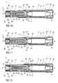
- Figure 1 shows two longitudinal sections in different section planes of an auto-injector 1, the different section planes approximately 90° rotated to each other.
- the auto-injector comprises an elongate outer casing 2.
- a syringe 3 with a hollow needle 4 is arranged in a proximal part of the auto-injector 1.
- a protective needle shield 5 is attached to the needle 4 and protruding through an orifice 6 at the proximal end P.
- a finger guard 7 in the shape of a sheet metal spring is arranged near the protective needle shield 5.
- the finger guard 7 comprises two spring arms 8 which are inwardly biased so they bear against the protective needle shield 5 as long as it is still in place.
- a respective locking arm 9 is assigned to each spring arm 8.
- the locking arms 9 are biased in distal direction D so they bear against a part of the spring arms 8 when the protective needle shield 5 is in place. As the protective needle shield 5 is pulled away from the needle 4 (see fig. 3 ) the spring arms 8 move inwards and relax leaving a small gap between them just wide enough to let the needle pass without touching it. This allows the locking arms 9 to come clear of the spring arms 8 and move distally into a position where they prevent the spring arms 8 from being pushed outward again so despite the rather big orifice 6 the user cannot touch the tip of the needle 4.
- the spring arms 8 and/or the locking arms 9 may be made of or comprise spring wire and/or plastic instead of sheet metal.
- the spring arms 8 and locking arms 9 may be integrally formed as illustrated. They may also be separate parts, e.g. attached to inner walls of the proximal part of the auto-injector 1.
- the spring arms 8 are essentially S-shaped with a longitudinal leg 8.1 in the middle and two transversal legs 8.2, 8.3 adjoining the longitudinal leg 8.1.
- the transversal legs 8.2, 8.3 are essentially parallel to each other.
- An outer transversal leg 8.2 of each spring arm 8 adjoins a wall portion 7.1 of the sheet metal spring 7.
- the other, inner transversal 8.3 leg of each spring arm 8 is intended to bear against the protective needle shield 5.
- a small gap is defined between the two inner transversal legs 8.3 of the spring arms 8.
- the locking arm 9 is a short arm with an outer end 9.1 adjoining a front portion 7.2 of the sheet metal spring 7 and with an inner end 9.2 bearing against the inner transversal leg 8.3 in distal direction D when the protective needle shield 5 is in place.
- the spring arms 8 move together and the locking arms 9 come clear of the inner transversal leg 8.3 when the joint between the inner transversal leg 8.3 and the longitudinal leg 8.1 passes the inner end 9.2.
- the inner end 9.2 locks behind the longitudinal leg 8.1 thus preventing the spring arm 8 from being pushed outward again.
- the tips of the spring arms' 8 inner transversal legs 8.3 where the spring arms 8 bear against the protective needle shield 5 are rounded off in order to facilitate removal of the protective needle shield 5.
- a trigger button 10 for releasing a torsion spring 11 is arranged at the distal end D of the auto-injector 1 .
- the trigger button 10 may be locked or unlocked by a locking collar 12 which is also arranged at the distal end D (see fig. 4 for details).
- the trigger button 10 is equipped with a number of longitudinal splines 10.1 that engage with respective slots 2.1 in the outer casing 2 so the trigger button 10 is prevented from rotating with respect to the outer casing 2 while allowed to be pushed into the outer casing 2 by a certain distance.
- At least one of the slots 2.1 has a lateral clearance 2.2.
- the locking collar 12 has an internal protrusion 12.1 (see fig. 4e ) also engaged in the slot 2.1.
- a small pin 12.2 provided in the collar 12 engages in a guiding clearance 2.3 of the slot 2.1 in order to prevent axial movement of the collar 12.
- the protrusion 12.1 is aligned with one of the splines 10.1 thus preventing the trigger button 10 from being pushed.
- a device cap (not shown) may be attached to the protective needle shield 5.
- the finger guard 7 locks into place to protect the user from accidental needlestick injuries.
- the user rotates the locking collar 12 by a small angle in the direction indicated by the arrow in figure 4c .
- the protrusion 12.1 is turned out of the alignment with the spline 10.1 and into the clearance 2.2.
- the trigger button 10 can now be depressed (see fig. 4d ).
- the auto-injector 1 is usually shipped with the trigger button 10 in the locked position.
- the torsion spring 11 is arranged inside the outer casing 2 and grounded with its distal end 11.1 in the outer casing 2 near the distal end D of the auto-injector 1 (cf. fig. 5 ).
- the proximal end 11.2 of the torsion spring 11 is grounded in a cam follower tube 13 arranged inside the torsion spring 11 and rotatable with respect to the outer casing 2.
- the cam follower tube 13 is engaged with an essentially tubular coupling member 14 telescoped into the cam follower tube 13.
- Fig. 5 shows the coupling member 14 in more detail.
- the distal end of the cam follower tube 13 and the coupling member 14 are provided with respective longitudinal splines 15 which are engaged with each other when the trigger button 10 is not pressed (cf. fig. 5a ).
- the trigger button 10 is splined to the outer casing 2 (cf. fig. 4 ) so the load of the torsion spring 11 is resolved statically.
- the trigger button 10 is attached to the coupling member 14 in a manner to prevent relative rotation.
- the trigger button 10 and the coupling member 14 may be a one-piece component.
- the cam follower tube 13 is telescoped with a lead screw tube 16.
- the lead screw tube 16 is supported and guided in a retraction slider tube 17 arranged in the proximal part of the outer casing 2 in a manner to prevent the lead screw tube 16 from rotating while allowing it to be moved axially in proximal direction P.
- the retraction slider tube 17 in turn is engaged with the outer casing 2 by flats 18 and latches 19 in a manner to prevent both rotation and translation with respect to the outer casing 2 at least in the initial situation shown in figure 1 . It will be shown in the following how the retraction slider tube 17 is disengaged from the latches 19 for being axially moved.
- the retraction slider tube 17 and the cam follower tube 13 are provided with respective shoulders 17.1, 13.1 held together by a coupling ring 20 for allowing relative rotation but preventing them from being independently axially moved.
- the lead screw tube 16 has an external lead screw which is engaged with the cam follower tube by a number of ball bearings 21. Rotation of the cam follower tube 13 therefore results in translative movement of the lead screw tube 16.
- the user places the auto-injector 1 with the orifice 6 ahead on the injection site and depresses the trigger button 10.
- the coupling member 14 is pushed further into the cam follower tube 13 so the splines 15 of the coupling member and the cam follower tube 13 come clear of each other.
- This rotation causes translative movement of the lead screw tube 16 in proximal direction P.
- a two part plunger with a plunger rear 22 and a plunger front 23 is arranged, the plunger rear 22 telescoped into the hollow plunger front 23.
- a plunger spring 24 in the shape of a compression spring is arranged which bears against the plunger rear 22 when the plunger rear 22 pushed in proximal direction P.
- the plunger front 23 in turn pushes against a stopper 25 arranged for sealing the syringe 3 distally and for displacing a liquid medicament M through the hollow needle 4.
- the syringe is held in a tubular syringe carrier 26 and supported at its proximal end therein.
- the plunger rear 22 is coupled for joined axial movement to the lead screw tube 16 by a plunger ball 27 arranged in a recess in the lead screw tube 16 and guided in a circumferential notch 28 of the plunger rear 22. In the initial position shown in figure 1 the plunger ball 27 is held in position by the cam follower tube 13 in order to keep the plunger rear 22 and lead screw tube 16 from disengaging.
- the external lead screw of the lead screw tube 16 has a variable pitch.
- the pitch is steeper in the proximal part of the external lead screw (cf. fig. 1 ). This allows for a rapid insertion of the hollow needle 4 into the patient's skin in order to avoid unnecessary pain for the patient.
- the load required to insert a siliconized fine gauge needle is thought to be in the region of 5 N, which is relatively low so a steep screw pitch can be used with little risk of the screw engagement locking.
- Figure 9 shows the auto-injector with the hollow needle 4 fully advanced.
- each ball 21 may be held in a respective longitudinal slot hole.
- each ball 21 may be engaged with a respective screw thread so the lead screw tube 16 would have a multi-start thread.
- the syringe carrier 26 has bottomed out at the proximal end P of the outer casing 2 thus defining an injection depth, e.g. for a subcutaneous injection.
- the auto-injector 1 is shown towards the end of the dose, i.e. just before the stopper 25 bottoms out in the syringe 3.
- viscous dampers 29 contained in pockets in the proximal end of the lead screw tube 16 contact small ribs 30 in the proximal end P of the outer casing 2.
- the plunger spring 24 is allowed to extend and complete the dose by fully advancing the stopper 25. This allows for fully emptying the syringe 3 before starting to retract the needle 4.
- the viscous damper 29 has a speed dependent load characteristic. In this instance the load from the torsion spring 11 is almost constant over the small axial travel of the viscous damper 29 so the speed can be tuned so that the plunger spring 24 has enough time to fully expel the residual contents of the syringe 3.
- the material of the viscous damper 29 may be viscoelastic foam or a fluid forced through a small orifice.
- a change in the lead screw pitch at this point allows a controlled increase in the mechanical advantage to apply sufficient force to the mechanism.
- the stopper 25 has bottomed out in the syringe and the lead screw tube 16 reaches the end of travel.
- the plunger ball 27 disengages the plunger rear 22 from the lead screw tube 16 by dropping out of its recess into a pocket 31 in the cam follower tube 13.
- the latches 19 are released by ramp features 32 of the lead screw tube 16 pushing them outward so the retraction slider tube 17 and the cam follower tube 13 are released from the outer casing 2 with respect to translative movement. Since the lead screw tube 16 has bottomed out at the proximal end P of the outer casing continued rotation of the torsion spring results in a backward movement of the retraction slider tube 17 and the cam follower tube 13 which is still rotating.
- the retraction slider tube 17 takes along the syringe carrier 26 and retracts it into the auto-injector 1 until the hollow needle 4 is fully covered.
- the retraction slider tube 17 may have one or more dog features extending inwardly through recesses in the lead screw tube 16 and engaging the syringe carrier 26 (dog features not illustrated).
- the auto-injector 1 may preferably be used for subcutaneous or intra-muscular injection, particularly for delivering one of an analgetic, an anticoagulant, insulin, an insulin derivate, heparin, Lovenox, a vaccine, a growth hormone, a peptide hormone, a protein, antibodies and complex carbohydrates.
Claims (7)
- Protège-doigt (7) pour un dispositif d'injection destiné à administrer une dose de médicament liquide (M), caractérisé en ce que le protège-doigt (7) comprend deux bras de ressort précontraints vers l'intérieur (8) prévus pour presser contre un fourreau d'aiguille protecteur (5) pouvant être disposé au niveau d'une aiguille creuse (4), le protège-doigt (7) ayant en outre un bras de verrouillage respectif (9) affecté à chaque bras de ressort (8), précontraint dans une direction distale (D) pour ainsi presser contre le bras de ressort respectif (8) lorsque le fourreau d'aiguille protecteur (5) est en place, les bras de ressort (8) étant prévus pour se déplacer vers l'intérieur lorsque le fourreau d'aiguille protecteur (5) est enlevé, en permettant ainsi aux bras de verrouillage (9) de se déplacer distalement dans une position dans laquelle ils empêchent les bras de ressort (8) d'être à nouveau poussés vers l'extérieur.
- Protège-doigt (7) selon la revendication 1, caractérisé en ce que les bras de ressort (8) et/ou les bras de verrouillage (9) sont constitués de tôle métallique et/ou de fil métallique à ressort et/ou de plastique.
- Protège-doigt (7) selon l'une quelconque des revendications 1 ou 2, caractérisé en ce que les bras de ressort (8) sont formés intégralement.
- Protège-doigt (7) selon l'une quelconque des revendications précédentes, caractérisé en ce que les bras de ressort (8) sont essentiellement en forme de S avec une branche longitudinale (8.1) au milieu et deux branches transversales (8.2, 8.3) joignant la branche longitudinale (8.1), une branche externe (8.2) des branches transversales (8.2, 8.3) de chaque bras de ressort (8) joignant une partie de paroi (7.1) du protège-doigt (7), une branche interne (8.3) des branches transversales (8.2, 8.3) de chaque bras de ressort (8) étant prévue pour presser contre le fourreau d'aiguille protecteur (5).
- Protège-doigt (7) selon la revendication 4, caractérisé en ce que le bras de verrouillage (9) présente une extrémité externe (9.1) joignant une partie avant (7.2) du protège-doigt (7) et une extrémité interne (9.2) prévue pour presser contre la branche transversale interne (8.3) dans la direction distale (D), le fourreau d'aiguille protecteur (5) étant en place et étant prévu pour se verrouiller derrière la branche longitudinale (8.1) lorsque le fourreau d'aiguille protecteur (5) est enlevé.
- Protège-doigt (7) selon l'une quelconque des revendications 4 ou 5, caractérisé en ce que les pointes des branches transversales internes (8.3) prévues pour presser contre le fourreau d'aiguille protecteur (5) sont arrondies.
- Dispositif d'injection destiné à administrer une dose de médicament liquide (M), le dispositif d'injection comprenant un protège-doigt (7) selon l'une quelconque des revendications 1 à 6, le protège-doigt (7) étant prévu dans un boîtier externe allongé (2) au niveau d'une extrémité proximale (P), le boîtier externe allongé (2) étant prévu pour contenir une seringue (3) avec une aiguille creuse (4) et un bouchon (25) pour fermer hermétiquement la seringue (3) et déplacer le médicament (M), le boîtier externe (2) ayant une extrémité distale (D) et l'extrémité proximale (P) avec un orifice (6) destiné à être appliqué contre un site d'injection, la seringue (3) étant disposée de manière à pouvoir coulisser par rapport au boîtier externe (2).
Priority Applications (1)
| Application Number | Priority Date | Filing Date | Title |
|---|---|---|---|
| EP11705852.9A EP2536455B1 (fr) | 2010-02-18 | 2011-02-16 | Protege-doigts pour dispositif d'injection |
Applications Claiming Priority (3)
| Application Number | Priority Date | Filing Date | Title |
|---|---|---|---|
| EP10153998 | 2010-02-18 | ||
| EP11705852.9A EP2536455B1 (fr) | 2010-02-18 | 2011-02-16 | Protege-doigts pour dispositif d'injection |
| PCT/EP2011/052300 WO2011101378A1 (fr) | 2010-02-18 | 2011-02-16 | Gaine d'aiguille pour un dispositif d'injection |
Publications (2)
| Publication Number | Publication Date |
|---|---|
| EP2536455A1 EP2536455A1 (fr) | 2012-12-26 |
| EP2536455B1 true EP2536455B1 (fr) | 2014-03-26 |
Family
ID=42790724
Family Applications (1)
| Application Number | Title | Priority Date | Filing Date |
|---|---|---|---|
| EP11705852.9A Active EP2536455B1 (fr) | 2010-02-18 | 2011-02-16 | Protege-doigts pour dispositif d'injection |
Country Status (6)
| Country | Link |
|---|---|
| US (1) | US9421336B2 (fr) |
| EP (1) | EP2536455B1 (fr) |
| JP (1) | JP5791637B2 (fr) |
| CA (1) | CA2789561A1 (fr) |
| DK (1) | DK2536455T3 (fr) |
| WO (1) | WO2011101378A1 (fr) |
Families Citing this family (67)
| Publication number | Priority date | Publication date | Assignee | Title |
|---|---|---|---|---|
| JP3993169B2 (ja) | 2002-02-11 | 2007-10-17 | アンタレス・ファーマ・インコーポレーテッド | 皮内注射器 |
| ES2716135T5 (es) | 2005-01-24 | 2023-06-15 | Antares Pharma Inc | Inyector de chorro asistido por aguja con jeringa precargada |
| US9352079B2 (en) * | 2005-02-25 | 2016-05-31 | Salvus Technology Limited | Safety needle accessory |
| WO2007131013A1 (fr) | 2006-05-03 | 2007-11-15 | Antares Pharma, Inc. | Injecteur de reconstitution à deux étages |
| US9144648B2 (en) | 2006-05-03 | 2015-09-29 | Antares Pharma, Inc. | Injector with adjustable dosing |
| US10420880B2 (en) | 2007-10-02 | 2019-09-24 | West Pharma. Services IL, Ltd. | Key for securing components of a drug delivery system during assembly and/or transport and methods of using same |
| CN101868273B (zh) * | 2007-10-02 | 2014-10-15 | 莱蒙德尔有限公司 | 外部药泵 |
| US9656019B2 (en) | 2007-10-02 | 2017-05-23 | Medimop Medical Projects Ltd. | Apparatuses for securing components of a drug delivery system during transport and methods of using same |
| US8814834B2 (en) | 2008-03-10 | 2014-08-26 | Antares Pharma, Inc. | Injector safety device |
| CA2732812C (fr) | 2008-08-05 | 2017-10-31 | Antares Pharma, Inc. | Injecteur a dosage multiple |
| WO2011101379A1 (fr) | 2010-02-18 | 2011-08-25 | Sanofi-Aventis Deutschland Gmbh | Injecteur automatique |
| EP2399635A1 (fr) | 2010-06-28 | 2011-12-28 | Sanofi-Aventis Deutschland GmbH | Auto-injecteur |
| NZ604014A (en) * | 2010-07-02 | 2014-04-30 | Sanofi Aventis Deutschland | Injection device with needle shield |
| NZ604076A (en) * | 2010-07-02 | 2014-05-30 | Sanofi Aventis Deutschland | Safety device for a pre-filled syringe and injection device |
| USRE48593E1 (en) | 2010-12-21 | 2021-06-15 | Sanofi-Aventis Deutschland Gmbh | Auto-injector |
| EP2468333A1 (fr) | 2010-12-21 | 2012-06-27 | Sanofi-Aventis Deutschland GmbH | Auto-injecteur |
| EP2468330A1 (fr) | 2010-12-21 | 2012-06-27 | Sanofi-Aventis Deutschland GmbH | Auto-injecteur |
| US9220660B2 (en) | 2011-07-15 | 2015-12-29 | Antares Pharma, Inc. | Liquid-transfer adapter beveled spike |
| US8496619B2 (en) | 2011-07-15 | 2013-07-30 | Antares Pharma, Inc. | Injection device with cammed ram assembly |
| EP2601988A1 (fr) | 2011-12-08 | 2013-06-12 | Sanofi-Aventis Deutschland GmbH | Support de seringue |
| EP2601990A1 (fr) * | 2011-12-08 | 2013-06-12 | Sanofi-Aventis Deutschland GmbH | Support de seringue |
| EP2601992A1 (fr) | 2011-12-08 | 2013-06-12 | Sanofi-Aventis Deutschland GmbH | Support de seringue |
| EP2601989A1 (fr) * | 2011-12-08 | 2013-06-12 | Sanofi-Aventis Deutschland GmbH | Support de seringue |
| JP6165786B2 (ja) | 2012-03-06 | 2017-07-19 | アンタレス・ファーマ・インコーポレーテッド | 離脱力特徴を備える充填シリンジ |
| CN104487114A (zh) | 2012-04-06 | 2015-04-01 | 安塔雷斯药品公司 | 针头辅助喷射注射给予睾酮组合物 |
| US9364610B2 (en) | 2012-05-07 | 2016-06-14 | Antares Pharma, Inc. | Injection device with cammed ram assembly |
| FI3659647T3 (fi) | 2013-02-11 | 2024-03-28 | Antares Pharma Inc | Neula-avusteinen suihkuinjektiolaite, jolla on pienennetty liipaisinvoima |
| GB2511317A (en) * | 2013-02-27 | 2014-09-03 | Owen Mumford Ltd | Automatic injection device |
| US9707354B2 (en) | 2013-03-11 | 2017-07-18 | Antares Pharma, Inc. | Multiple dosage injector with rack and pinion dosage system |
| EP2823841A1 (fr) | 2013-07-09 | 2015-01-14 | Sanofi-Aventis Deutschland GmbH | Auto-injecteur |
| EP2923714A1 (fr) | 2014-03-28 | 2015-09-30 | Sanofi-Aventis Deutschland GmbH | Auto-injecteur declenché par contact avec la peau |
| CN106413779B (zh) * | 2014-05-07 | 2020-06-05 | 安姆根有限公司 | 具有减震元件的自助注射器 |
| US10149943B2 (en) | 2015-05-29 | 2018-12-11 | West Pharma. Services IL, Ltd. | Linear rotation stabilizer for a telescoping syringe stopper driverdriving assembly |
| TW201700117A (zh) | 2015-06-03 | 2017-01-01 | 賽諾菲阿凡提斯德意志有限公司 | 用於自動注射器的注射筒托架和組裝方法 |
| TW201705994A (zh) | 2015-06-03 | 2017-02-16 | 賽諾菲阿凡提斯德意志有限公司 | 自動注射器及組裝方法 |
| EP3117854A1 (fr) | 2015-07-15 | 2017-01-18 | Sanofi-Aventis Deutschland GmbH | Dispositif d'administration de medicaments avec un mécanisme de contrôle du protecteur d'aiguille et d'activation du dispositif |
| US10086145B2 (en) | 2015-09-22 | 2018-10-02 | West Pharma Services Il, Ltd. | Rotation resistant friction adapter for plunger driver of drug delivery device |
| US10576207B2 (en) | 2015-10-09 | 2020-03-03 | West Pharma. Services IL, Ltd. | Angled syringe patch injector |
| US9987432B2 (en) | 2015-09-22 | 2018-06-05 | West Pharma. Services IL, Ltd. | Rotation resistant friction adapter for plunger driver of drug delivery device |
| AT517801B1 (de) * | 2015-09-24 | 2017-09-15 | Pharma Consult Gmbh | Injektionsvorrichtung, insbesondere Autoinjektor |
| JP7017512B2 (ja) | 2015-10-09 | 2022-02-08 | ウェスト ファーマ サービシーズ イスラエル リミテッド | 充填済流体容器の屈曲流体路型付属物 |
| WO2018070978A1 (fr) * | 2016-10-10 | 2018-04-19 | West Pharma. Services IL, Ltd. | Mécanisme d'insertion et de rétraction d'aiguille |
| CN111544704B (zh) | 2016-01-21 | 2022-06-03 | 西医药服务以色列有限公司 | 自动注射器中的力牵制 |
| WO2017127215A1 (fr) | 2016-01-21 | 2017-07-27 | Medimop Medical Projects Ltd. | Mécanisme d'introduction et de rétraction d'aiguille |
| CN113041432B (zh) | 2016-01-21 | 2023-04-07 | 西医药服务以色列有限公司 | 包括视觉指示物的药剂输送装置 |
| DK3429663T3 (da) * | 2016-03-15 | 2020-09-28 | Amgen Inc | Reduktion af sandsynligheden for glasbrud i anordninger til indgivelse af lægemidler |
| US11389597B2 (en) | 2016-03-16 | 2022-07-19 | West Pharma. Services IL, Ltd. | Staged telescopic screw assembly having different visual indicators |
| US10376647B2 (en) | 2016-03-18 | 2019-08-13 | West Pharma. Services IL, Ltd. | Anti-rotation mechanism for telescopic screw assembly |
| USD819198S1 (en) | 2016-04-28 | 2018-05-29 | Amgen Inc. | Autoinjector with removable cap |
| US20180015224A1 (en) | 2016-07-13 | 2018-01-18 | California Institute Of Technology | Dampers and Methods for Performing Measurements in an Autoinjector |
| CH712753A2 (de) | 2016-07-28 | 2018-01-31 | Tecpharma Licensing Ag | Trennen einer Nadelschutzkappe von einem Produktbehälter und Verfahren zum Montieren einer Injektionsvorrichtung. |
| JP6869327B2 (ja) | 2016-08-01 | 2021-05-12 | ウェスト ファーマ サービシーズ イスラエル リミテッド | 回転防止カートリッジ |
| EP3630226A1 (fr) | 2017-05-30 | 2020-04-08 | West Pharma. Services Il, Ltd. | Train d'entraînement modulaire pour injecteur pouvant être porté |
| IL270784B2 (en) | 2017-07-14 | 2023-11-01 | Amgen Inc | Needle insertion-extraction system with a double torsion spring system |
| TWI725517B (zh) * | 2018-09-24 | 2021-04-21 | 瑞士商瑞健醫療股份有限公司 | 針護罩移除器和包含有針護罩移除器的藥物輸送裝置 |
| USD1010811S1 (en) | 2019-09-30 | 2024-01-09 | Amgen Inc. | Handheld drug delivery device |
| US11173254B2 (en) | 2020-03-27 | 2021-11-16 | Medivena Sp. Z O.O. | Needle-based device with a safety mechanism implemented therein |
| US20230355889A1 (en) | 2020-03-27 | 2023-11-09 | Jaroslaw Moleda | Needle-based device based on direct wing-based coupling of a needle shield to a barrel thereof and safety mechanism implemented therein |
| US11224699B2 (en) | 2020-03-27 | 2022-01-18 | Medivena Sp. Z O.O. | Needle-based device with a safety mechanism implemented therein |
| JP2021500643S (ja) | 2020-11-05 | 2022-12-27 | 注射器 | |
| USD973866S1 (en) | 2020-11-05 | 2022-12-27 | Amgen Inc. | Handheld drug delivery device |
| USD974547S1 (en) | 2020-11-05 | 2023-01-03 | Amgen Inc. | Handheld drug delivery device |
| USD985116S1 (en) | 2021-03-10 | 2023-05-02 | Amgen Inc. | Handheld drug delivery device |
| USD985118S1 (en) | 2021-03-10 | 2023-05-02 | Amgen Inc. | Handheld drug delivery device |
| USD985117S1 (en) | 2021-03-10 | 2023-05-02 | Amgen Inc. | Handheld drug delivery device |
| USD985119S1 (en) | 2021-03-30 | 2023-05-02 | Amgen Inc. | Handheld drug delivery device |
| WO2023285152A1 (fr) * | 2021-07-16 | 2023-01-19 | Shl Medical Ag | Mécanisme d'activation dépendant de la séquence utilisant un rotateur |
Family Cites Families (9)
| Publication number | Priority date | Publication date | Assignee | Title |
|---|---|---|---|---|
| US6117108A (en) * | 1997-08-20 | 2000-09-12 | Braun Melsungen Ag | Spring clip safety IV catheter |
| US6280419B1 (en) * | 1999-08-09 | 2001-08-28 | Arrow International, Inc. | Hypodermic needle guard |
| WO2002017996A1 (fr) | 2000-08-29 | 2002-03-07 | Novo Nordisk A/S | Dispositif automatique d'injection a retrait de l'aiguille par torsion |
| DE20106697U1 (de) * | 2001-04-18 | 2001-10-31 | Braun Melsungen Ag | Kathetereinführvorrichtung |
| US20050075609A1 (en) * | 2003-10-01 | 2005-04-07 | Latona Patrick C. | Protective needle clips |
| MXPA06009272A (es) * | 2004-02-13 | 2007-02-02 | Smiths Medical Asd Inc | Protector para la punta de una aguja. |
| GB0724944D0 (en) * | 2007-12-20 | 2008-01-30 | Ucb Pharma Sa | Auto injector |
| DE202009009119U1 (de) | 2009-07-02 | 2009-12-31 | B. Braun Melsungen Ag | Schutzvorrichtung für eine Injektionsnadel |
| JP5797209B2 (ja) * | 2010-02-18 | 2015-10-21 | サノフィ−アベンティス・ドイチュラント・ゲゼルシャフト・ミット・ベシュレンクテル・ハフツング | 自動注射器 |
-
2011
- 2011-02-16 WO PCT/EP2011/052300 patent/WO2011101378A1/fr active Application Filing
- 2011-02-16 JP JP2012553302A patent/JP5791637B2/ja active Active
- 2011-02-16 US US13/578,997 patent/US9421336B2/en active Active
- 2011-02-16 EP EP11705852.9A patent/EP2536455B1/fr active Active
- 2011-02-16 CA CA2789561A patent/CA2789561A1/fr not_active Abandoned
- 2011-02-16 DK DK11705852.9T patent/DK2536455T3/da active
Also Published As
| Publication number | Publication date |
|---|---|
| WO2011101378A1 (fr) | 2011-08-25 |
| US20130190693A1 (en) | 2013-07-25 |
| JP5791637B2 (ja) | 2015-10-07 |
| CA2789561A1 (fr) | 2011-08-25 |
| JP2013519473A (ja) | 2013-05-30 |
| EP2536455A1 (fr) | 2012-12-26 |
| US9421336B2 (en) | 2016-08-23 |
| DK2536455T3 (da) | 2014-06-23 |
Similar Documents
| Publication | Publication Date | Title |
|---|---|---|
| EP2536455B1 (fr) | Protege-doigts pour dispositif d'injection | |
| US11484653B1 (en) | Auto-injector | |
| EP2536453B1 (fr) | Auto-injecteur | |
| US9616181B2 (en) | Auto-injector | |
| EP2536451B1 (fr) | Auto-injecteur avec un ressort à torsion | |
| EP2544738B1 (fr) | Dispositif d'injection | |
| EP2538996B1 (fr) | Auto-injecteur avec protection et capuchon d'aiguille | |
| US9358351B2 (en) | Gearbox |
Legal Events
| Date | Code | Title | Description |
|---|---|---|---|
| PUAI | Public reference made under article 153(3) epc to a published international application that has entered the european phase |
Free format text: ORIGINAL CODE: 0009012 |
|
| 17P | Request for examination filed |
Effective date: 20120918 |
|
| AK | Designated contracting states |
Kind code of ref document: A1 Designated state(s): AL AT BE BG CH CY CZ DE DK EE ES FI FR GB GR HR HU IE IS IT LI LT LU LV MC MK MT NL NO PL PT RO RS SE SI SK SM TR |
|
| AX | Request for extension of the european patent |
Extension state: BA ME |
|
| GRAP | Despatch of communication of intention to grant a patent |
Free format text: ORIGINAL CODE: EPIDOSNIGR1 |
|
| INTG | Intention to grant announced |
Effective date: 20130906 |
|
| GRAS | Grant fee paid |
Free format text: ORIGINAL CODE: EPIDOSNIGR3 |
|
| GRAA | (expected) grant |
Free format text: ORIGINAL CODE: 0009210 |
|
| AK | Designated contracting states |
Kind code of ref document: B1 Designated state(s): AL AT BE BG CH CY CZ DE DK EE ES FI FR GB GR HR HU IE IS IT LI LT LU LV MC MK MT NL NO PL PT RO RS SE SI SK SM TR |
|
| AX | Request for extension of the european patent |
Extension state: BA ME |
|
| REG | Reference to a national code |
Ref country code: GB Ref legal event code: FG4D |
|
| REG | Reference to a national code |
Ref country code: CH Ref legal event code: EP |
|
| REG | Reference to a national code |
Ref country code: AT Ref legal event code: REF Ref document number: 658614 Country of ref document: AT Kind code of ref document: T Effective date: 20140415 |
|
| REG | Reference to a national code |
Ref country code: DE Ref legal event code: R096 Ref document number: 602011005764 Country of ref document: DE Effective date: 20140430 |
|
| REG | Reference to a national code |
Ref country code: IE Ref legal event code: FG4D |
|
| REG | Reference to a national code |
Ref country code: SE Ref legal event code: TRGR |
|
| REG | Reference to a national code |
Ref country code: DK Ref legal event code: T3 Effective date: 20140620 |
|
| PG25 | Lapsed in a contracting state [announced via postgrant information from national office to epo] |
Ref country code: LT Free format text: LAPSE BECAUSE OF FAILURE TO SUBMIT A TRANSLATION OF THE DESCRIPTION OR TO PAY THE FEE WITHIN THE PRESCRIBED TIME-LIMIT Effective date: 20140326 Ref country code: NO Free format text: LAPSE BECAUSE OF FAILURE TO SUBMIT A TRANSLATION OF THE DESCRIPTION OR TO PAY THE FEE WITHIN THE PRESCRIBED TIME-LIMIT Effective date: 20140626 |
|
| REG | Reference to a national code |
Ref country code: AT Ref legal event code: MK05 Ref document number: 658614 Country of ref document: AT Kind code of ref document: T Effective date: 20140326 |
|
| REG | Reference to a national code |
Ref country code: NL Ref legal event code: VDEP Effective date: 20140326 |
|
| REG | Reference to a national code |
Ref country code: LT Ref legal event code: MG4D |
|
| PG25 | Lapsed in a contracting state [announced via postgrant information from national office to epo] |
Ref country code: FI Free format text: LAPSE BECAUSE OF FAILURE TO SUBMIT A TRANSLATION OF THE DESCRIPTION OR TO PAY THE FEE WITHIN THE PRESCRIBED TIME-LIMIT Effective date: 20140326 |
|
| PG25 | Lapsed in a contracting state [announced via postgrant information from national office to epo] |
Ref country code: LV Free format text: LAPSE BECAUSE OF FAILURE TO SUBMIT A TRANSLATION OF THE DESCRIPTION OR TO PAY THE FEE WITHIN THE PRESCRIBED TIME-LIMIT Effective date: 20140326 Ref country code: HR Free format text: LAPSE BECAUSE OF FAILURE TO SUBMIT A TRANSLATION OF THE DESCRIPTION OR TO PAY THE FEE WITHIN THE PRESCRIBED TIME-LIMIT Effective date: 20140326 Ref country code: RS Free format text: LAPSE BECAUSE OF FAILURE TO SUBMIT A TRANSLATION OF THE DESCRIPTION OR TO PAY THE FEE WITHIN THE PRESCRIBED TIME-LIMIT Effective date: 20140326 |
|
| PG25 | Lapsed in a contracting state [announced via postgrant information from national office to epo] |
Ref country code: EE Free format text: LAPSE BECAUSE OF FAILURE TO SUBMIT A TRANSLATION OF THE DESCRIPTION OR TO PAY THE FEE WITHIN THE PRESCRIBED TIME-LIMIT Effective date: 20140326 Ref country code: CY Free format text: LAPSE BECAUSE OF FAILURE TO SUBMIT A TRANSLATION OF THE DESCRIPTION OR TO PAY THE FEE WITHIN THE PRESCRIBED TIME-LIMIT Effective date: 20140326 Ref country code: BG Free format text: LAPSE BECAUSE OF FAILURE TO SUBMIT A TRANSLATION OF THE DESCRIPTION OR TO PAY THE FEE WITHIN THE PRESCRIBED TIME-LIMIT Effective date: 20140626 Ref country code: IS Free format text: LAPSE BECAUSE OF FAILURE TO SUBMIT A TRANSLATION OF THE DESCRIPTION OR TO PAY THE FEE WITHIN THE PRESCRIBED TIME-LIMIT Effective date: 20140726 Ref country code: CZ Free format text: LAPSE BECAUSE OF FAILURE TO SUBMIT A TRANSLATION OF THE DESCRIPTION OR TO PAY THE FEE WITHIN THE PRESCRIBED TIME-LIMIT Effective date: 20140326 Ref country code: NL Free format text: LAPSE BECAUSE OF FAILURE TO SUBMIT A TRANSLATION OF THE DESCRIPTION OR TO PAY THE FEE WITHIN THE PRESCRIBED TIME-LIMIT Effective date: 20140326 Ref country code: BE Free format text: LAPSE BECAUSE OF FAILURE TO SUBMIT A TRANSLATION OF THE DESCRIPTION OR TO PAY THE FEE WITHIN THE PRESCRIBED TIME-LIMIT Effective date: 20140326 Ref country code: RO Free format text: LAPSE BECAUSE OF FAILURE TO SUBMIT A TRANSLATION OF THE DESCRIPTION OR TO PAY THE FEE WITHIN THE PRESCRIBED TIME-LIMIT Effective date: 20140326 |
|
| PG25 | Lapsed in a contracting state [announced via postgrant information from national office to epo] |
Ref country code: AT Free format text: LAPSE BECAUSE OF FAILURE TO SUBMIT A TRANSLATION OF THE DESCRIPTION OR TO PAY THE FEE WITHIN THE PRESCRIBED TIME-LIMIT Effective date: 20140326 Ref country code: SK Free format text: LAPSE BECAUSE OF FAILURE TO SUBMIT A TRANSLATION OF THE DESCRIPTION OR TO PAY THE FEE WITHIN THE PRESCRIBED TIME-LIMIT Effective date: 20140326 Ref country code: PL Free format text: LAPSE BECAUSE OF FAILURE TO SUBMIT A TRANSLATION OF THE DESCRIPTION OR TO PAY THE FEE WITHIN THE PRESCRIBED TIME-LIMIT Effective date: 20140326 Ref country code: ES Free format text: LAPSE BECAUSE OF FAILURE TO SUBMIT A TRANSLATION OF THE DESCRIPTION OR TO PAY THE FEE WITHIN THE PRESCRIBED TIME-LIMIT Effective date: 20140326 |
|
| PG25 | Lapsed in a contracting state [announced via postgrant information from national office to epo] |
Ref country code: PT Free format text: LAPSE BECAUSE OF FAILURE TO SUBMIT A TRANSLATION OF THE DESCRIPTION OR TO PAY THE FEE WITHIN THE PRESCRIBED TIME-LIMIT Effective date: 20140728 |
|
| REG | Reference to a national code |
Ref country code: DE Ref legal event code: R097 Ref document number: 602011005764 Country of ref document: DE |
|
| PLBE | No opposition filed within time limit |
Free format text: ORIGINAL CODE: 0009261 |
|
| STAA | Information on the status of an ep patent application or granted ep patent |
Free format text: STATUS: NO OPPOSITION FILED WITHIN TIME LIMIT |
|
| 26N | No opposition filed |
Effective date: 20150106 |
|
| PG25 | Lapsed in a contracting state [announced via postgrant information from national office to epo] |
Ref country code: IT Free format text: LAPSE BECAUSE OF FAILURE TO SUBMIT A TRANSLATION OF THE DESCRIPTION OR TO PAY THE FEE WITHIN THE PRESCRIBED TIME-LIMIT Effective date: 20140326 |
|
| REG | Reference to a national code |
Ref country code: DE Ref legal event code: R097 Ref document number: 602011005764 Country of ref document: DE Effective date: 20150106 |
|
| PG25 | Lapsed in a contracting state [announced via postgrant information from national office to epo] |
Ref country code: SI Free format text: LAPSE BECAUSE OF FAILURE TO SUBMIT A TRANSLATION OF THE DESCRIPTION OR TO PAY THE FEE WITHIN THE PRESCRIBED TIME-LIMIT Effective date: 20140326 |
|
| REG | Reference to a national code |
Ref country code: DE Ref legal event code: R119 Ref document number: 602011005764 Country of ref document: DE |
|
| PG25 | Lapsed in a contracting state [announced via postgrant information from national office to epo] |
Ref country code: LU Free format text: LAPSE BECAUSE OF FAILURE TO SUBMIT A TRANSLATION OF THE DESCRIPTION OR TO PAY THE FEE WITHIN THE PRESCRIBED TIME-LIMIT Effective date: 20150216 |
|
| PG25 | Lapsed in a contracting state [announced via postgrant information from national office to epo] |
Ref country code: MC Free format text: LAPSE BECAUSE OF FAILURE TO SUBMIT A TRANSLATION OF THE DESCRIPTION OR TO PAY THE FEE WITHIN THE PRESCRIBED TIME-LIMIT Effective date: 20140326 |
|
| REG | Reference to a national code |
Ref country code: IE Ref legal event code: MM4A |
|
| REG | Reference to a national code |
Ref country code: FR Ref legal event code: PLFP Year of fee payment: 6 |
|
| PG25 | Lapsed in a contracting state [announced via postgrant information from national office to epo] |
Ref country code: IE Free format text: LAPSE BECAUSE OF NON-PAYMENT OF DUE FEES Effective date: 20150216 Ref country code: DE Free format text: LAPSE BECAUSE OF NON-PAYMENT OF DUE FEES Effective date: 20150901 |
|
| PG25 | Lapsed in a contracting state [announced via postgrant information from national office to epo] |
Ref country code: GR Free format text: LAPSE BECAUSE OF FAILURE TO SUBMIT A TRANSLATION OF THE DESCRIPTION OR TO PAY THE FEE WITHIN THE PRESCRIBED TIME-LIMIT Effective date: 20140627 |
|
| PG25 | Lapsed in a contracting state [announced via postgrant information from national office to epo] |
Ref country code: MT Free format text: LAPSE BECAUSE OF FAILURE TO SUBMIT A TRANSLATION OF THE DESCRIPTION OR TO PAY THE FEE WITHIN THE PRESCRIBED TIME-LIMIT Effective date: 20140326 |
|
| REG | Reference to a national code |
Ref country code: FR Ref legal event code: PLFP Year of fee payment: 7 |
|
| PG25 | Lapsed in a contracting state [announced via postgrant information from national office to epo] |
Ref country code: SM Free format text: LAPSE BECAUSE OF FAILURE TO SUBMIT A TRANSLATION OF THE DESCRIPTION OR TO PAY THE FEE WITHIN THE PRESCRIBED TIME-LIMIT Effective date: 20140326 Ref country code: HU Free format text: LAPSE BECAUSE OF FAILURE TO SUBMIT A TRANSLATION OF THE DESCRIPTION OR TO PAY THE FEE WITHIN THE PRESCRIBED TIME-LIMIT; INVALID AB INITIO Effective date: 20110216 |
|
| PG25 | Lapsed in a contracting state [announced via postgrant information from national office to epo] |
Ref country code: TR Free format text: LAPSE BECAUSE OF FAILURE TO SUBMIT A TRANSLATION OF THE DESCRIPTION OR TO PAY THE FEE WITHIN THE PRESCRIBED TIME-LIMIT Effective date: 20140326 |
|
| REG | Reference to a national code |
Ref country code: FR Ref legal event code: PLFP Year of fee payment: 8 |
|
| PG25 | Lapsed in a contracting state [announced via postgrant information from national office to epo] |
Ref country code: MK Free format text: LAPSE BECAUSE OF FAILURE TO SUBMIT A TRANSLATION OF THE DESCRIPTION OR TO PAY THE FEE WITHIN THE PRESCRIBED TIME-LIMIT Effective date: 20140326 |
|
| PG25 | Lapsed in a contracting state [announced via postgrant information from national office to epo] |
Ref country code: AL Free format text: LAPSE BECAUSE OF FAILURE TO SUBMIT A TRANSLATION OF THE DESCRIPTION OR TO PAY THE FEE WITHIN THE PRESCRIBED TIME-LIMIT Effective date: 20140326 |
|
| PGFP | Annual fee paid to national office [announced via postgrant information from national office to epo] |
Ref country code: SE Payment date: 20190212 Year of fee payment: 9 |
|
| REG | Reference to a national code |
Ref country code: SE Ref legal event code: EUG |
|
| PG25 | Lapsed in a contracting state [announced via postgrant information from national office to epo] |
Ref country code: SE Free format text: LAPSE BECAUSE OF NON-PAYMENT OF DUE FEES Effective date: 20200217 |
|
| PGFP | Annual fee paid to national office [announced via postgrant information from national office to epo] |
Ref country code: GB Payment date: 20221230 Year of fee payment: 13 |
|
| PGFP | Annual fee paid to national office [announced via postgrant information from national office to epo] |
Ref country code: DK Payment date: 20230213 Year of fee payment: 13 Ref country code: CH Payment date: 20230307 Year of fee payment: 13 |
|
| P01 | Opt-out of the competence of the unified patent court (upc) registered |
Effective date: 20230421 |
|
| PGFP | Annual fee paid to national office [announced via postgrant information from national office to epo] |
Ref country code: FR Payment date: 20231212 Year of fee payment: 14 |