EP2536151A2 - Procédé et appareil de traitement de signal vidéo - Google Patents
Procédé et appareil de traitement de signal vidéo Download PDFInfo
- Publication number
- EP2536151A2 EP2536151A2 EP11742484A EP11742484A EP2536151A2 EP 2536151 A2 EP2536151 A2 EP 2536151A2 EP 11742484 A EP11742484 A EP 11742484A EP 11742484 A EP11742484 A EP 11742484A EP 2536151 A2 EP2536151 A2 EP 2536151A2
- Authority
- EP
- European Patent Office
- Prior art keywords
- prediction
- block
- prediction mode
- sub
- current block
- Prior art date
- Legal status (The legal status is an assumption and is not a legal conclusion. Google has not performed a legal analysis and makes no representation as to the accuracy of the status listed.)
- Withdrawn
Links
Images


Classifications
-
- H—ELECTRICITY
- H04—ELECTRIC COMMUNICATION TECHNIQUE
- H04N—PICTORIAL COMMUNICATION, e.g. TELEVISION
- H04N19/00—Methods or arrangements for coding, decoding, compressing or decompressing digital video signals
- H04N19/10—Methods or arrangements for coding, decoding, compressing or decompressing digital video signals using adaptive coding
- H04N19/134—Methods or arrangements for coding, decoding, compressing or decompressing digital video signals using adaptive coding characterised by the element, parameter or criterion affecting or controlling the adaptive coding
- H04N19/157—Assigned coding mode, i.e. the coding mode being predefined or preselected to be further used for selection of another element or parameter
-
- H—ELECTRICITY
- H04—ELECTRIC COMMUNICATION TECHNIQUE
- H04N—PICTORIAL COMMUNICATION, e.g. TELEVISION
- H04N19/00—Methods or arrangements for coding, decoding, compressing or decompressing digital video signals
- H04N19/10—Methods or arrangements for coding, decoding, compressing or decompressing digital video signals using adaptive coding
- H04N19/102—Methods or arrangements for coding, decoding, compressing or decompressing digital video signals using adaptive coding characterised by the element, parameter or selection affected or controlled by the adaptive coding
- H04N19/103—Selection of coding mode or of prediction mode
- H04N19/11—Selection of coding mode or of prediction mode among a plurality of spatial predictive coding modes
-
- H—ELECTRICITY
- H04—ELECTRIC COMMUNICATION TECHNIQUE
- H04N—PICTORIAL COMMUNICATION, e.g. TELEVISION
- H04N19/00—Methods or arrangements for coding, decoding, compressing or decompressing digital video signals
- H04N19/10—Methods or arrangements for coding, decoding, compressing or decompressing digital video signals using adaptive coding
- H04N19/102—Methods or arrangements for coding, decoding, compressing or decompressing digital video signals using adaptive coding characterised by the element, parameter or selection affected or controlled by the adaptive coding
- H04N19/119—Adaptive subdivision aspects, e.g. subdivision of a picture into rectangular or non-rectangular coding blocks
-
- H—ELECTRICITY
- H04—ELECTRIC COMMUNICATION TECHNIQUE
- H04N—PICTORIAL COMMUNICATION, e.g. TELEVISION
- H04N19/00—Methods or arrangements for coding, decoding, compressing or decompressing digital video signals
- H04N19/10—Methods or arrangements for coding, decoding, compressing or decompressing digital video signals using adaptive coding
- H04N19/134—Methods or arrangements for coding, decoding, compressing or decompressing digital video signals using adaptive coding characterised by the element, parameter or criterion affecting or controlling the adaptive coding
- H04N19/136—Incoming video signal characteristics or properties
-
- H—ELECTRICITY
- H04—ELECTRIC COMMUNICATION TECHNIQUE
- H04N—PICTORIAL COMMUNICATION, e.g. TELEVISION
- H04N19/00—Methods or arrangements for coding, decoding, compressing or decompressing digital video signals
- H04N19/10—Methods or arrangements for coding, decoding, compressing or decompressing digital video signals using adaptive coding
- H04N19/134—Methods or arrangements for coding, decoding, compressing or decompressing digital video signals using adaptive coding characterised by the element, parameter or criterion affecting or controlling the adaptive coding
- H04N19/157—Assigned coding mode, i.e. the coding mode being predefined or preselected to be further used for selection of another element or parameter
- H04N19/159—Prediction type, e.g. intra-frame, inter-frame or bidirectional frame prediction
-
- H—ELECTRICITY
- H04—ELECTRIC COMMUNICATION TECHNIQUE
- H04N—PICTORIAL COMMUNICATION, e.g. TELEVISION
- H04N19/00—Methods or arrangements for coding, decoding, compressing or decompressing digital video signals
- H04N19/10—Methods or arrangements for coding, decoding, compressing or decompressing digital video signals using adaptive coding
- H04N19/169—Methods or arrangements for coding, decoding, compressing or decompressing digital video signals using adaptive coding characterised by the coding unit, i.e. the structural portion or semantic portion of the video signal being the object or the subject of the adaptive coding
- H04N19/17—Methods or arrangements for coding, decoding, compressing or decompressing digital video signals using adaptive coding characterised by the coding unit, i.e. the structural portion or semantic portion of the video signal being the object or the subject of the adaptive coding the unit being an image region, e.g. an object
- H04N19/176—Methods or arrangements for coding, decoding, compressing or decompressing digital video signals using adaptive coding characterised by the coding unit, i.e. the structural portion or semantic portion of the video signal being the object or the subject of the adaptive coding the unit being an image region, e.g. an object the region being a block, e.g. a macroblock
-
- H—ELECTRICITY
- H04—ELECTRIC COMMUNICATION TECHNIQUE
- H04N—PICTORIAL COMMUNICATION, e.g. TELEVISION
- H04N19/00—Methods or arrangements for coding, decoding, compressing or decompressing digital video signals
- H04N19/10—Methods or arrangements for coding, decoding, compressing or decompressing digital video signals using adaptive coding
- H04N19/169—Methods or arrangements for coding, decoding, compressing or decompressing digital video signals using adaptive coding characterised by the coding unit, i.e. the structural portion or semantic portion of the video signal being the object or the subject of the adaptive coding
- H04N19/186—Methods or arrangements for coding, decoding, compressing or decompressing digital video signals using adaptive coding characterised by the coding unit, i.e. the structural portion or semantic portion of the video signal being the object or the subject of the adaptive coding the unit being a colour or a chrominance component
-
- H—ELECTRICITY
- H04—ELECTRIC COMMUNICATION TECHNIQUE
- H04N—PICTORIAL COMMUNICATION, e.g. TELEVISION
- H04N19/00—Methods or arrangements for coding, decoding, compressing or decompressing digital video signals
- H04N19/46—Embedding additional information in the video signal during the compression process
- H04N19/463—Embedding additional information in the video signal during the compression process by compressing encoding parameters before transmission
-
- H—ELECTRICITY
- H04—ELECTRIC COMMUNICATION TECHNIQUE
- H04N—PICTORIAL COMMUNICATION, e.g. TELEVISION
- H04N19/00—Methods or arrangements for coding, decoding, compressing or decompressing digital video signals
- H04N19/70—Methods or arrangements for coding, decoding, compressing or decompressing digital video signals characterised by syntax aspects related to video coding, e.g. related to compression standards
-
- H—ELECTRICITY
- H04—ELECTRIC COMMUNICATION TECHNIQUE
- H04N—PICTORIAL COMMUNICATION, e.g. TELEVISION
- H04N19/00—Methods or arrangements for coding, decoding, compressing or decompressing digital video signals
- H04N19/50—Methods or arrangements for coding, decoding, compressing or decompressing digital video signals using predictive coding
- H04N19/593—Methods or arrangements for coding, decoding, compressing or decompressing digital video signals using predictive coding involving spatial prediction techniques
-
- H—ELECTRICITY
- H04—ELECTRIC COMMUNICATION TECHNIQUE
- H04N—PICTORIAL COMMUNICATION, e.g. TELEVISION
- H04N19/00—Methods or arrangements for coding, decoding, compressing or decompressing digital video signals
- H04N19/60—Methods or arrangements for coding, decoding, compressing or decompressing digital video signals using transform coding
- H04N19/61—Methods or arrangements for coding, decoding, compressing or decompressing digital video signals using transform coding in combination with predictive coding
Definitions
- the present invention relates to a method and apparatus for processing a video signal, and more particularly, to a method and apparatus for efficiently encoding or decoding a video signal.
- Compression encoding refers to a series of signal processing techniques of transmitting digitized information via a communication line or storing digitized information in a form suitable for a storage medium.
- video, audio and text are subjected to compression encoding.
- a technique of performing compression encoding with respect to video is referred to as video compression.
- Compression encoding of video is achieved by eliminating redundant information in consideration of spatial correlation, temporal correlation, probabilistic correlation, etc.
- the present invention is contrived to solve the above demand and an object of the present invention is to provide a video signal processing method capable of efficiently compressing a video signal using various motion prediction methods.
- Another object of the present invention is to provide an efficient and accurate method even in the case of using prediction blocks having various shapes in intra prediction.
- Another object of the present invention is to improve a compression rate by efficiently allocating a number indicating a prediction mode.
- Another object of the present invention is to provide a more accurate and efficient prediction method in intra prediction of a chrominance component.
- Another object of the present invention is to efficiently process a video signal by more accurately predicting a motion vector of a current block in inter prediction.
- the object of the present invention can be achieved by providing various prediction block shapes using information such as a partition flag or a merge flag in intra prediction.
- inter prediction it is possible to acquire a more accurate motion vector prediction value by predicting a motion vector with respect to an intra block without motion information.
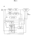
- FIG. 1 is a schematic block diagram of a video signal encoding apparatus according to an embodiment of the present invention
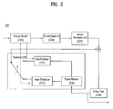
- FIG. 2 is a schematic block diagram of a video signal decoding apparatus according to an embodiment of the present invention.
- FIG. 3 is a diagram showing nine prediction modes and directions thereof in an intra 4x4 mode of H.264/AVC;
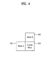
- FIG. 4 is a diagram showing neighboring blocks used to derive a most probable mode as a prediction mode of a current block according to an embodiment of the present invention
- FIG. 5 is a diagram showing partition forms of a 2Nx2N prediction block
- FIG. 6 is a diagram showing an arbitrary prediction direction in an intra prediction mode
- FIGs. 7 to 8 are diagrams illustrating prediction mode number allocation according to embodiments of the present invention.
- FIGs, 9(a) to 9(c) are diagrams showing use of neighboring chrominance components of a prediction block for intra prediction if one prediction block is quartered according to an embodiment of the present invention
- FIG. 10 is a diagram showing an area used by each sub-prediction block for intra prediction if one prediction block is quartered according to an embodiment of the present invention
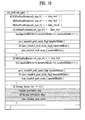
- FIG. 11 is a diagram showing an example of the syntax including flag information indicating whether a new intra prediction mode is used
- FIG. 12 is a flowchart illustrating a process of restoring a chrominance component
- FIG. 13 is a diagram showing neighboring blocks used to predict a motion vector of an intra block
- FIG. 14 is a diagram illustrating a method of utilizing a template matching method in order to find a motion vector of an intra block according to an embodiment of the present invention
- FIG. 15 is a diagram showing an example of the syntax including flag information indicating whether a new intra prediction mode is used.
- FIG. 16 is a diagram showing an example of the syntax indicating whether a hybrid mode among inter prediction modes is used.
- the object of the present invention can be achieved by providing a method of processing a video signal including acquiring partition information indicating whether a current block is partitioned, partitioning the current block into square sub-blocks if the partition information indicates that the current block is partitioned, acquiring prediction values of the sub-blocks using restored pixels in a current picture, and restoring the current block using the prediction values.
- the restored pixels in the current picture used to acquire the prediction values include restored pixels of other sub-blocks included in the current block.
- the method may further include acquiring merge flag information indicating whether the sub-blocks of the current block are merged, and, if the merge flag information indicates that the sub-blocks of the current block are merged, the prediction values may be acquired with respect to a shape of the merged block. At this time, sub-blocks which are vertically or horizontally adjacent may be merged and the merged sub-block may have a rectangular shape.
- the method may further include predicting a prediction mode of the current block using a prediction mode of an upper neighboring block or a left neighboring block of the current block, the acquiring the prediction values may use reference pixels located in a direction indicated by the prediction mode, and a partition of the sub-blocks may be taken into consideration in the prediction of the prediction mode.
- a prediction number can be more efficiently allocated to the prediction mode of the current block by considering a occurrence frequency. For example, one prediction mode having a smaller value between an upper neighboring block and a left neighboring block may be selected and a low prediction number may be allocated to the other value or to adjacent prediction modes of the selected prediction mode.
- the following terms may be construed based on the following criteria, and terms which are not used herein may also be construed based on the following criteria.
- the term coding may be construed as encoding or decoding and the term information includes values, parameters, coefficients, elements, etc. and the meanings thereof may be differently construed according to circumstances and the present invention is not limited thereto.
- the term "unit” indicates a basic video processing unit or a specific position of video and may be used interchangeably with the term “block” or "area” as necessary.
- FIG. 1 is a schematic block diagram of a video signal encoding apparatus 100 according to an embodiment of the present invention.
- the encoding apparatus 100 of the present invention includes a transform part 110, a quantizer 115, an inverse quantizer 120, an inverse transform part 125, a filter part 130, a predictor 150 and an entropy coder 160.
- the transform part 110 transforms a pixel value of a received video signal and acquires a transform coefficient value.
- a transform method for example, Discrete Cosine Transform (DCT), Wavelet Transform, etc. may be used.
- DCT is performed by partitioning the received video signal into blocks each having a predetermined size.
- the quantizer 115 quantizes the transform coefficient value output from the transform part 110.
- the inverse quantizer 120 inversely quantizes the transform coefficient value and the inverse transform part 125 restores a pixel value using the inversely quantized transform coefficient value.
- the filter part 130 performs a filtering operation for improving quality of the restored image.
- the filter part may include a deblocking filter and/or an adaptive loop filter, for example.
- the filtered image is output or stored in a frame memory 156 so as to be used as a reference image.
- An intra predictor 152 performs prediction within a current image and an inter predictor 154 predicts a current image using at least one reference image stored in the frame memory 156.
- the intra predictor 152 performs intra prediction from restored areas of the current image and sends the intra coding information to the entropy coder 160.
- the inter predictor 154 may be configured to include a motion compensator 162 and a motion estimator 164.
- the motion estimator 164 acquires a motion vector value of a current area by referring to a specific restored area.
- the motion estimator 164 may send position information (a reference frame, a motion vector, etc.) of a reference area to the entropy coder 160 to be included in a bitstream.
- the motion compensator 162 performs inter motion compensation using the motion vector value received from the motion estimator 164.
- the entropy coder 160 entropy-codes the quantized transform coefficient, inter coding information, intra coding information and the reference area information received from the inter predictor 154 to generate a video signal bitstream.
- the entropy coder 160 may use a variable length coding (VLC) scheme, an arithmetic coding scheme, etc.
- VLC variable length coding
- the VLC scheme transforms input symbols into continuous codewords and the length of the codeword is variable. For example, frequently occurred symbols may be expressed by a short codeword and symbols which are not frequently occurred may be expressed by a long codeword.
- a Context-based Adaptive Variable Length Coding (CAVLC) scheme may be used as the VLC scheme.
- CAVLC Context-based Adaptive Variable Length Coding
- the arithmetic coding scheme transforms continuous data symbols into one prime number. It is possible to obtain an optimal prime number bit necessary to express each symbol using arithmetic coding.
- CABAC
- FIG. 2 is a schematic block diagram of a video signal decoding apparatus 200 according to an embodiment of the present invention.
- the decoding apparatus 200 of the present invention includes an entropy decoder 210, an inverse quantizer 220, an inverse transform part 225, a filter unit 230 and a predictor 250.
- the entropy decoder 210 entropy-decodes a video signal stream and extracts an coding type, a transform coefficient of each area, a motion vector, etc.
- the inverse quantizer 220 inversely quantizes the entropy-decoded transform efficient and the inverse transform part 225 restores an pixel value using the inversely quantized transform coefficient.
- the predictor 250 includes an intra predictor 252 and an inter predictor 254 and restores a prediction image using an coding type, a transform coefficient of each area and a motion vector decoded through the entropy decoder 210.
- the intra predictor 252 generates an intra prediction image from decoded samples of a current image.
- the inter predictor 254 generates a prediction image using the reference image stored in the frame memory 256.
- the pixel value output from the inverse transform part 225 is added to the prediction image output from the intra predictor 252 or the inter predictor 254 to generate a restored video frame.
- the filter part 230 filters the restored video frame to improve image quality.
- a deblocking filter for reducing a block distortion phenomenon and an adaptive loop filter for eliminating distortion of an entire image may be included.
- the filtered image is output as a final image and is stored in the frame memory 256 in order to be used as the reference image.
- a coding unit is a basic unit for processing an image in a video signal processing procedure, e.g., intra/inter prediction, transform, quantization and/or entropy coding.
- the size of the coding unit used to code one image may not be constant.
- the coding unit may have a rectangular shape and one coding unit may be partitioned into several coding units. For example, one coding unit having a size of 2Nx2N may be partitioned into four coding units having a size of N ⁇ N.
- the coding unit may be recursively partitioned and need not be partitioned into coding units having the same shape. For convenience of the coding and processing procedure, there is a limit to a maximum size or a minimum size of the coding unit.
- information indicating whether the coding unit is partitioned may be specified. For example, if a flag value indicating partition/non-partition is 1, a block corresponding to the node is partitioned into four blocks and, if the flag value is 0, the coding unit may be processed without partition.
- the structure of the coding unit may be expressed using a recursive tree structure. That is, the coding unit partitioned has child nodes corresponding in number to the number of partitioned coding units using one image or a maximum-size coding unit as a root. Accordingly, a coding unit which is no longer partitioned becomes a leaf node. If it is assumed that one coding unit is only partitioned into squares, one coding unit may be partitioned into four coding units and thus a tree representing a coding unit structure becomes a quad tree.
- An encoder may select an optimal size of the coding unit by taking the properties (e.g., resolution) of the video signal or coding efficiency into consideration, and information about the size of the coding unit or information for driving the size of the coding unit may be included in a bitstream. For example, the maximum size of the coding unit and the maximum depth of the tree may be defined. If the coding unit is partitioned into squares, the height and width of the coding unit is half of the height and width of the coding unit of a parent node. Accordingly, it is possible to obtain a minimum coding unit size using the above information.
- a minimum size of the coding unit and a maximum depth of the tree are defined and the maximum size of the coding unit may be derived using the minimum size of the coding unit and the maximum depth of the tree.
- the actual size of the coding unit is expressed by a log value based on 2 so as to improve transmission efficiency.
- a decoder may acquire information indicating whether a current unit is partitioned. If such information is acquired (transmitted) only under a specific condition, efficiency can be increased. For example, since the current unit can be partitioned when addition of a current coding unit size and information about a current position is less than the size of the image and the current coding unit size is greater than a predetermined minimum coding unit size, it is possible to acquire information indicating whether the coding unit is partitioned only in this case.
- the size of the partitioned coding unit becomes half of the current coding unit and the current coding unit is partitioned into four square coding units based on the current processing position.
- the partitioned coding units are repeatedly subjected to the above processes.
- Image prediction (motion compensation) for coding is performed with respect to a coding unit (that is, a leaf node of a coding unit tree) which is no longer partitioned.
- a basic unit for performing such prediction is referred to a prediction unit or a prediction block.
- the prediction block may be partitioned to have various shapes and each partitioned part is referred to as a sub-prediction unit or sub-prediction block.
- One prediction block may be partitioned into sub-prediction blocks having a symmetrical shape such as a square or a rectangle, an asymmetrical shape or a geometric shape.
- the bitstream may include information indicating whether a prediction block is partitioned or information about the shape of a sub-prediction block. Alternatively, such information may be derived from other information.
- Prediction mode information indicates which mode is used. In a special case, it is possible to reduce the amount of transmitted information by deriving prediction mode information instead of transmitting prediction mode information.
- the intra predictor 252 performs intra prediction for predicting a pixel value of a target unit from restored areas of the current image.
- the pixel value of the current unit may be predicted from pixels of units located on the upper, left, left-upper and/or right-upper side of the current unit.
- a method of using reference pixels located in various directions such as a vertical direction, a horizontal direction and a diagonal direction or using an average value of restored pixels may be used in predicting a pixel value.
- FIG. 3 shows nine prediction modes and directions thereof in an intra 4x4 mode of H.264/AVC.
- prediction mode calculating an average value by referring only to pixels which do not deviate from a picture boundary is referred to "DC" prediction (prediction mode 2).
- the encoder transmits information as to which mode is used in intra prediction and the decoder acquires a prediction value of a current prediction block according to the mode information. In transmitting such information, if a smaller number is allocated as a prediction direction generation frequency is higher, the amount of transmitted information is reduced and thus compression efficiency can be increased. Referring to 3, numbers 0 to 8 may be allocated to the nine prediction modes in the order of frequency.
- FIG. 4 shows neighboring blocks used to predict MPM of a current block according to an embodiment of the present invention.
- a left neighboring block 420 and an upper neighboring block 430 of a current block 410 are already coded.
- the prediction mode of the left neighboring block and the prediction mode of the upper neighboring block may be compared and the prediction mode having the smaller number may be used as the MPM of the current block.
- the prediction mode information of such neighboring blocks may not be used to derive the intra prediction mode of the current block. Accordingly, information about the states of the neighboring blocks may be used to derive the prediction mode of the current block.
- a DC prediction mode may be set as the MPM of the current block.
- the prediction mode to which the smaller number is allocated may be selected from the prediction modes of the two neighboring blocks.
- the size and shape of the prediction block may be varied.
- FIG. 5 shows the case in which a minimum coding unit having a size of 2Nx2N, that is, a prediction block, of an image is partitioned into blocks using various methods.
- a maximum-size coding unit 500 may be partitioned into several coding units and the minimum coding unit 510 becomes a basic unit of prediction.
- one prediction block may not be partitioned or may be partitioned into four square sub-prediction blocks each having a size of N ⁇ N or rectangular sub-prediction blocks having a size of N ⁇ 2N or 2N ⁇ N.
- the decoder may receive information about various prediction block partition shapes and partition a prediction block.
- a prediction block having a rectangular shape may be generated by vertically or horizontally merging sub-prediction blocks having a size of N ⁇ N and flag information indicating whether merging has been performed may be used.
- a method of deriving an intra prediction mode of a current prediction block is used by taking various prediction block shapes into consideration.
- a prediction mode may be derived as follows. If the left neighboring block 420 is not available and the upper neighboring block 430 is not available or is coded in an inter prediction mode, a DC prediction mode is derived as the MPM of the current block. If the left neighboring block 420 is coded in an inter prediction mode and the upper neighboring block 430 is not available or is coded in an inter prediction mode, a DC prediction mode is derived as the MPM of the current block.
- the intra prediction mode of the neighboring block coded in the intra prediction mode is derived as the MPM of the current block. That is, if the left neighboring block 420 is not available or is coded in an inter prediction mode and the upper neighboring block 430 is coded in an intra prediction mode, the intra prediction mode of the upper neighboring block 430 may be used as the MPM of the current block. In other cases, as described above, a prediction mode, to which the smaller number is allocated, between the prediction modes of the two neighboring blocks is set as the MPM of the current block.
- the MPM of the current prediction block may be derived as follows. If the left neighboring block 420 is not available and the upper neighboring block 430 is not available or is coded in an inter prediction mode, a DC prediction mode is derived as the MPM of the current block. If the left neighboring block 420 is coded in an inter prediction mode and the upper neighboring block 430 is not available or is coded in an inter prediction mode, a DC prediction mode is derived as the MPM of the current block.
- the intra prediction mode of the neighboring block coded in the intra prediction mode is derived as the MPM of the current block. That is, if the left neighboring block 420 is not available or is coded in an inter prediction mode and the upper neighboring block 430 is coded in an intra prediction mode, the intra prediction mode of the upper neighboring block 430 may be used as the MPM of the current block. In other cases, as described above, the prediction mode of the upper neighboring block 430 is derived as the MPM of the current block.
- the MPM of the current prediction block may be derived as follows. If the left neighboring block 420 is not available and the upper neighboring block 430 is not available or is coded in an inter prediction mode, a DC prediction mode is derived as the MPM of the current block. If the left neighboring block 420 is coded in an inter prediction mode and the upper neighboring block 430 is not available or is coded in an inter prediction mode, a DC prediction mode is derived as the MPM of the current block.
- the intra prediction mode of the neighboring block coded in the intra prediction mode is derived as the MPM of the current block. That is, if the left neighboring block 420 is not available or is coded in an inter prediction mode and the upper neighboring block 430 is coded in an intra prediction mode, the intra prediction mode of the upper neighboring block 430 may be used as the MPM of the current block. In other cases, as described above, the prediction mode of the left neighboring block 420 is derived as the MPM of the current block.
- the prediction mode of the current block is predicted as a most probable prediction mode
- information indicating whether the MPM which is a predictor of the prediction mode of the current block is equal to a prediction direction of actual prediction may be transmitted. If the prediction directions are different from each other, the information indicates that the predicted direction is different from the prediction direction of actual prediction and information indicating which prediction mode except for the prediction direction is used for prediction coding may be transmitted. If the prediction directions are the same, since information about the prediction mode need not to be transmitted, it is possible to increase compression efficiency.
- FIG. 6 shows an arbitrary prediction direction in an intra prediction mode.
- the arbitrary prediction direction may be represented by a slope between a current pixel 610 and a reference pixel 620 used for prediction.
- the size of the prediction block which is a unit for performing prediction in one image, may be varied (e.g., 4x4, 8x8, ..., 64x64) and the kind of the prediction direction may be more various as the size of the prediction block is larger.
- fixed prediction numbers are not allocated but prediction numbers are allocated according to prediction direction occurrence frequency, thereby increasing encoding efficiency.
- the prediction mode of the current block is not MPM
- the prediction mode of the current block has a prediction mode having a smaller value, has directivity similar to the predicted prediction mode or may be a neighboring prediction mode which is not selected for deriving the MPM.
- FIG. 7 for example, an upper neighboring block 730 of a current block 710 is coded in a Vert mode and a left neighboring block 720 is coded in a Hori_down mode.
- FIG. 8 shows several methods of allocating a prediction mode number to the current block shown in FIG. 7 according to several embodiments of the present invention.
- the MPM value of the current block is derived as the prediction mode "Vert mode" of the upper neighboring block. Except for Vert mode which is the current MPM, numbers from 0 to 7 are sequentially allocated to the remaining prediction modes using the existing method.
- the remaining neighboring prediction mode which is not selected for prediction of the prediction mode may be regarded as a next most probable prediction mode and a smallest mode number may be allocated to the remaining neighboring prediction mode. That is, in the above example, the Hori_down mode of the unselected left block may become a next most probable mode of the MPM.
- the remaining prediction mode numbers are sequentially allocated using the existing method.
- Proposed Method 1 of FIG. 8 shows prediction numbers which are newly allocated using such a method.
- a prediction mode close to the prediction value of the prediction mode may be regarded as a most probable prediction mode and may be considered first.
- Vert_left and Vert_right close to Vert may be preferentially considered.
- the remaining prediction mode numbers are sequentially allocated using the existing method.
- Proposed Method 2 of FIG. 8 shows prediction numbers which are newly allocated using such a method. Although only two adjacent directions are considered in the present embodiment, the range of the adjacent direction may be extended as necessary.
- a low prediction number is preferentially allocated to the prediction mode of an unselected neighboring block and the mode of the adjacent direction of the predicted prediction mode.
- Proposed Method 3 of FIG. 8 shows prediction numbers which are newly allocated using such a method.
- the present invention is not limited to these embodiments and a determination as to which mode a smaller prediction number is allocated may be reversely made.
- prediction modes of nine directions are described for convenience of description, prediction modes of more directions may be necessary according to the size of the prediction block as described above. Even when the number of prediction modes is increased, the prediction mode allocation method of the present invention is applicable.
- FIGs. 9(a) to 9(c) show use of chrominance components adjacent to a prediction block for intra prediction if one prediction block 900 is quartered into four sub-prediction blocks 910, 920, 930 and 940.
- the chrominance components of the partitioned sub-prediction blocks are predicted using left and upper outer areas 950 and 960 of the decoded block.
- the pixel prediction value according to each prediction mode may be derived as follows.
- the size of each sub-prediction block is 4 ⁇ 4.
- FIG. 9(a) shows which outer area is used to predict each sub-prediction block in a DC prediction mode.
- an average value is obtained using available pixels of the outer area of the prediction block 900 and is used as a prediction value.
- the prediction value of the current block is as follows.
- the prediction value of the current block may be expressed by an average value of the left and upper outer areas 950 and 960
- the prediction value of the current block may be expressed by the average value of the left outer area 950
- the prediction value of the current block may be expressed by the average value of the upper outer area 960
- the prediction value of the current block may be expressed as the above.
- bitDepth c indicates the bit depth of a current block.
- the prediction value of the current block is expressed by the following equation:
- FIGs. 9(a) and 9(b) show areas used in each sub-prediction block in a horizontal prediction mode and a vertical prediction mode, respectively. These are expressed by the following equations.
- Equations of a plane mode are as follows.
- each sub-prediction block may not use neighboring pixels of the prediction block but may use neighboring pixels of each sub-prediction block as a reference pixel. If restoration is not performed in prediction block units but is sequentially performed in sub-prediction block units, information about other sub-prediction blocks may be used when restoring a specific sub-prediction block.
- FIG. 10 shows an area used by each sub-prediction block for intra prediction if one prediction block is quartered according to an embodiment of the present invention. Although the sub-prediction blocks generally use the same prediction mode, different prediction modes may be used in some cases.
- subHeightC and subWidthC indicate the height and width of the sub-prediction unit, respectively.
- a chrominance component may be calculated using a luminance component. More specifically, the equation of the chrominance component according to a linear relationship with the luminance component may be expressed by the following equation when the luminance component and the chrominance component are respectively L(x, y) and C(x, y).
- a prediction value may be approximated by the following equation.
- L'(x, y) and C'(x, y) indicate the restored luminance component and chrominance component of neighboring blocks, respectively.
- a method of predicting a chrominance component using a luminance component may be added as a new intra prediction mode of the chrominance component.
- flag information indicating whether such a prediction mode is used may be transmitted to the decoder.
- FIG. 12 shows a process of restoring a chrominance component.
- a current block is predicted using restored pixels (S1210), is transformed (S1220), and is restored (S1230). Such a process may be performed with respect to the prediction block or in sub-prediction block units as described above.
- the chrominance component is described in FIG. 12
- the luminance component may be restored in sub-prediction block units to be used for other sub-prediction blocks.
- inter predictor 254 a method of estimating motion from a previously encoded image (or frame) and predicting a current block is used. This prediction method is referred to as inter prediction.
- inter prediction there is a need for a process of deriving information about a reference image and a motion vector indicating a reference block.
- a motion vector of any block has correlation with a motion vector of a neighboring block. Accordingly, a motion vector of a current block is predicted from a neighboring block and only a difference vector thereof is coded, thereby reducing the amount of bits to be coded and increasing compression efficiency.
- a motion vector prediction value for example, a median or average value of motion vectors of neighboring blocks may be used.
- the motion vector of the intra block may be regarded as a specific value (e.g., 0) and may be generally used to predict the motion information of the current block.
- the block coded in the intra prediction mode is referred to as an intra block and the block coded in the inter prediction mode is referred to as an inter block.
- a determination as to which block size is used or which prediction mode is used may be most efficiently made through rate-distortion optimization. In general, since correlation with a previous image (or frame) is high, inter prediction is selected rather than intra prediction.
- intra prediction is used if inter prediction cannot be performed, for example, in case of an intra image, or if correlation between images is low and thus inter prediction performance is deteriorated. If an incorrect motion vector prediction value mvp is obtained, a motion vector difference mvd to be transmitted is too large and rate-distortion cost is increased or if a residual value is increased due to large change between two pictures and thus rate-distortion cost is increased, the intra prediction mode may be selected instead of the inter prediction mode. In addition, even in case of texture in which intra prediction may be performed, intra prediction is more advantageous than inter prediction. Accordingly, it is possible to predict a motion vector of an intra block by taking such causes into consideration.
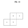
- FIG. 13 shows neighboring blocks used to predict the motion vector of an intra block X.
- neighboring blocks A, B and C located at the left side, upper side, and right-upper side of the intra block may be used.
- the motion vector prediction value mvx of X may be obtained by a median of the motion vectors mvA, mvb and mvC of the neighboring blocks A, B and C.
- all the blocks A, B and C are inter blocks (for example, all the reference image indexes refA, refB and refC of A, B and C are not -1).
- a smallest value among the reference image indexes of A, B and C may be selected as the index of the reference image.
- mvX median (mvA, mvB, mvC)
- the motion vector of a corresponding prediction block in a reference picture may be used as a motion vector of the intra block. If the corresponding block is an intra block, a specific value (e.g., 0) may be used.
- information indicating which value is used as a motion vector prediction value may be transmitted.
- this information may represent which of the motion vectors of the neighboring blocks A, B and C or the medians mvA, mvB and mvC thereof is used as the motion vector prediction value.
- the intra prediction mode is selected because intra prediction efficiency is better than inter prediction efficiency
- a method of finding a motion vector of an intra block at a decoder may be used.
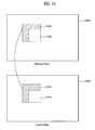
- FIG. 14 shows a method of using a template matching method in order to find a motion vector of an intra block according to an embodiment of the present invention.
- FIG. 14 shows a current frame 1400A including a current block 1410A and a reference frame 1400B.
- a target area is the current block 1410A to be predicted using template matching.
- a template refers to an area to be found in the reference frame 1400B and an restored area is used as the template.
- the left-upper side of the current block 1410A is an restored area and a right-lower side is an area before restoration.
- the template area 1420A may be composed of pixels located at a constant interval to contact the left and upper edge of the target area.
- An area 1420B similar to the template area 1420A of the current frame is found in the reference frame 1400B.
- the motion vector of the area 1410B corresponding to the target block on the periphery of the template similar area 2420B in the reference frame may be acquired and used as the motion vector prediction value of the target block 1410A.
- the template area is composed of a constant pixel area contacting the left and upper edge in the present embodiment, an area composed of an already restored area may be used as the template.
- the chrominance component may be derived using the luminance component without inter prediction as described above as shown in the following equation.
- prediction using a luminance component may be added as one of an inter prediction mode.
- Flag information indicating whether such a prediction mode is used may be transmitted to the decoder.
- FIG. 15 shows an example of the syntax including such flag information chroma_estimation_flag. For example, if an approximate value mode using a luminance component is used, the flag information is 1.
- a chrominance component may be predicted using the luminance value according to the flag information or motion compensation using a motion vector may be performed using the existing method.
- the chrominance component may be predicted using an estimation value using a luminance signal and an average of a prediction value using motion compensation.
- an estimation value C1'(x, y) using a luminance signal and C2'(x, y) using motion compensation may be expressed as follows.
- FIG. 16 shows the syntax in this case.
- the aforementioned embodiments are proposed by combining constituent components and characteristics of the present invention according to a predetermined format.
- the individual constituent components or characteristics should be considered optional factors on the condition that there is no additional remark. If required, the individual constituent components or characteristics may not be combined with other components or characteristics. Also, some constituent components and/or characteristics may be combined to implement the embodiments of the present invention.
- the order of operations to be disclosed in the embodiments of the present invention may be changed to another. Some components or characteristics of any embodiment may also be included in other embodiments, or may be replaced with those of the other embodiments as necessary.
- the decoding/encoding method according to the present invention may be embodied as a program to be executed on a computer and may be stored in a computer-readable recording medium, and multimedia data having a data structure according to the present invention may be stored in a computer-readable recording medium.
- the computer-readable recording medium may be any type of recording device in which data can be stored in a computer-readable manner. Examples of the computer-readable recording medium include a ROM, a RAM, a CD-ROM, a magnetic tape, a floppy disc, optical data storage, and a carrier wave (e.g., data transmission over the Internet).
- a bitstream generated by the above encoding method may be stored in a computer-readable recording medium or may be transmitted over a wired/wireless communication network.
- the embodiments of the present invention can be implemented by a variety of means, for example, hardware, firmware, software, or a combination thereof.
- the present invention can be implemented with application specific integrated circuits (ASICs), digital signal processors (DSPs), digital signal processing devices (DSPDs), programmable logic devices (PLDs), field programmable gate arrays (FPGAs), a processor, a controller, a microcontroller, a microprocessor, etc.
- ASICs application specific integrated circuits
- DSPs digital signal processors
- DSPDs digital signal processing devices
- PLDs programmable logic devices
- FPGAs field programmable gate arrays
- processor a controller, a microcontroller, a microprocessor, etc.
- the present invention is applicable to encoding or decoding of a video signal.
Landscapes
- Engineering & Computer Science (AREA)
- Multimedia (AREA)
- Signal Processing (AREA)
- Compression Or Coding Systems Of Tv Signals (AREA)
- Compression, Expansion, Code Conversion, And Decoders (AREA)
Applications Claiming Priority (5)
| Application Number | Priority Date | Filing Date | Title |
|---|---|---|---|
| US30327210P | 2010-02-10 | 2010-02-10 | |
| US34601410P | 2010-05-18 | 2010-05-18 | |
| US34825910P | 2010-05-26 | 2010-05-26 | |
| US34919610P | 2010-05-27 | 2010-05-27 | |
| PCT/KR2011/000898 WO2011099792A2 (fr) | 2010-02-10 | 2011-02-10 | Procédé et appareil de traitement de signal vidéo |
Publications (2)
| Publication Number | Publication Date |
|---|---|
| EP2536151A2 true EP2536151A2 (fr) | 2012-12-19 |
| EP2536151A4 EP2536151A4 (fr) | 2014-03-19 |
Family
ID=44368314
Family Applications (1)
| Application Number | Title | Priority Date | Filing Date |
|---|---|---|---|
| EP11742484.6A Withdrawn EP2536151A4 (fr) | 2010-02-10 | 2011-02-10 | Procédé et appareil de traitement de signal vidéo |
Country Status (5)
| Country | Link |
|---|---|
| US (1) | US9100649B2 (fr) |
| EP (1) | EP2536151A4 (fr) |
| KR (1) | KR20120129944A (fr) |
| CN (1) | CN102754442A (fr) |
| WO (1) | WO2011099792A2 (fr) |
Cited By (4)
| Publication number | Priority date | Publication date | Assignee | Title |
|---|---|---|---|---|
| JP2017507618A (ja) * | 2013-12-30 | 2017-03-16 | クゥアルコム・インコーポレイテッドQualcomm Incorporated | 3dビデオコーディングにおける大型予測ブロックのセグメントごとのdcコーディングの簡易化 |
| CN106688237A (zh) * | 2014-09-30 | 2017-05-17 | 凯迪迪爱通信技术有限公司 | 视频编码设备、视频译码设备、视频压缩传输系统、视频编码方法、视频译码方法和程序 |
| US10264280B2 (en) | 2011-06-09 | 2019-04-16 | Qualcomm Incorporated | Enhanced intra-prediction mode signaling for video coding using neighboring mode |
| US11700384B2 (en) | 2011-07-17 | 2023-07-11 | Qualcomm Incorporated | Signaling picture size in video coding |
Families Citing this family (48)
| Publication number | Priority date | Publication date | Assignee | Title |
|---|---|---|---|---|
| CN105472386B (zh) * | 2010-04-09 | 2018-09-18 | Lg电子株式会社 | 处理视频数据的方法和装置 |
| US8902978B2 (en) * | 2010-05-30 | 2014-12-02 | Lg Electronics Inc. | Enhanced intra prediction mode signaling |
| KR20120016991A (ko) * | 2010-08-17 | 2012-02-27 | 오수미 | 인터 프리딕션 방법 |
| KR101953384B1 (ko) | 2011-03-06 | 2019-03-04 | 엘지전자 주식회사 | 휘도 샘플을 이용한 색차 블록의 화면 내 예측 방법 및 이러한 방법을 사용하는 장치 |
| WO2012140821A1 (fr) | 2011-04-12 | 2012-10-18 | パナソニック株式会社 | Procédé de codage de vidéo animée, appareil de codage de vidéo animée, procédé de décodage de vidéo animée, appareil de décodage de vidéo animée et appareil de codage/décodage de vidéo animée |
| US9485518B2 (en) | 2011-05-27 | 2016-11-01 | Sun Patent Trust | Decoding method and apparatus with candidate motion vectors |
| PL3614665T3 (pl) | 2011-05-27 | 2022-07-04 | Sun Patent Trust | Sposób kodowania obrazów, urządzenie do kodowania obrazów, sposób dekodowania obrazów, urządzenie do dekodowania obrazów, i urządzenie do kodowania i dekodowania obrazów |
| KR101889582B1 (ko) | 2011-05-31 | 2018-08-20 | 선 페이턴트 트러스트 | 동화상 부호화 방법, 동화상 부호화 장치, 동화상 복호화 방법, 동화상 복호화 장치, 및, 동화상 부호화 복호화 장치 |
| WO2012167418A1 (fr) * | 2011-06-07 | 2012-12-13 | Technicolor (China) Technology Co., Ltd. | Procédé pour coder et/ou décoder des images sur un niveau de macrobloc à l'aide d'une prévision interne |
| US9282338B2 (en) * | 2011-06-20 | 2016-03-08 | Qualcomm Incorporated | Unified merge mode and adaptive motion vector prediction mode candidates selection |
| PL2725791T3 (pl) | 2011-06-23 | 2024-02-26 | Sun Patent Trust | Sposób dekodowania obrazów, sposób kodowania obrazów |
| WO2012176464A1 (fr) * | 2011-06-24 | 2012-12-27 | パナソニック株式会社 | Procédé de décodage d'image, procédé de codage d'image, dispositif de décodage d'image, dispositif de codage d'image et dispositif de codage/décodage d'image |
| HUE046468T2 (hu) | 2011-06-24 | 2020-03-30 | Sun Patent Trust | Kódoló eljárás és kódoló berendezés |
| MX2013013483A (es) | 2011-06-27 | 2014-02-27 | Panasonic Corp | Metodo de decodificacion de imagenes, metodo de codificacion de imagenes, aparato de decodificacion de imagenes, aparato de codificacion de imagenes y aparato de codificacion y decodificacion de imagenes. |
| MY165469A (en) * | 2011-06-28 | 2018-03-23 | Sun Patent Trust | Image decoding method, image coding method, image decoding apparatus, image coding apparatus, and image coding and decoding apparatus |
| MX2013010892A (es) * | 2011-06-29 | 2013-12-06 | Panasonic Corp | Metodo de decodificacion de imagenes, metodo de codificacion de imagenes, aparato de decodificacion de imagenes, aparato de codificacion de imagenes y aparato de codificacion y decodificacion de imagenes. |
| ES2908152T3 (es) | 2011-06-30 | 2022-04-27 | Sun Patent Trust | Procedimiento de decodificación de imágenes |
| KR102060619B1 (ko) | 2011-06-30 | 2019-12-30 | 선 페이턴트 트러스트 | 화상 복호 방법, 화상 부호화 방법, 화상 복호 장치, 화상 부호화 장치 및 화상 부호화 복호 장치 |
| KR102271116B1 (ko) | 2011-07-11 | 2021-06-29 | 선 페이턴트 트러스트 | 화상 복호 방법, 화상 부호화 방법, 화상 복호 장치, 화상 부호화 장치 및 화상 부호화 복호 장치 |
| CN103703780B (zh) * | 2011-07-22 | 2016-12-07 | 株式会社日立制作所 | 运动图像解码方法及图像编码方法 |
| EP2741499A4 (fr) | 2011-08-03 | 2014-12-10 | Panasonic Ip Corp America | Procédé de codage vidéo, appareil de codage vidéo, procédé de décodage vidéo, appareil de décodage vidéo et appareil de codage/décodage vidéo |
| CN103858428B (zh) * | 2011-10-19 | 2018-07-03 | 太阳专利托管公司 | 图像编码方法、图像编码装置、图像解码方法及图像解码装置 |
| HUE050655T2 (hu) * | 2011-10-24 | 2020-12-28 | Innotive Ltd | Képdekódolási eljárás |
| RS60786B1 (sr) * | 2012-01-20 | 2020-10-30 | Dolby Laboratories Licensing Corp | Postupak mapiranja režima intra predikcije |
| WO2013139212A1 (fr) * | 2012-03-21 | 2013-09-26 | Mediatek Singapore Pte. Ltd. | Procédé et appareil pour une dérivation et un codage en mode intra dans un système de codage vidéo scalable |
| WO2013162275A1 (fr) * | 2012-04-24 | 2013-10-31 | 엘지전자 주식회사 | Procédé et appareil permettant de traiter des signaux vidéo |
| JP6005572B2 (ja) * | 2013-03-28 | 2016-10-12 | Kddi株式会社 | 動画像符号化装置、動画像復号装置、動画像符号化方法、動画像復号方法、およびプログラム |
| US9426465B2 (en) * | 2013-08-20 | 2016-08-23 | Qualcomm Incorporated | Sub-PU level advanced residual prediction |
| KR102378459B1 (ko) * | 2014-06-30 | 2022-03-24 | 한국전자통신연구원 | 움직임 병합 모드에서 시점 합성 예측 후보의 중복성 제거 장치 및 방법 |
| CN112584140B (zh) * | 2014-11-27 | 2024-08-13 | 株式会社Kt | 对视频信号进行解码或编码的方法 |
| CN107005696B (zh) | 2014-11-27 | 2020-06-26 | 株式会社Kt | 视频信号处理方法和设备 |
| KR20160067580A (ko) * | 2014-12-04 | 2016-06-14 | 삼성전자주식회사 | 영상 데이터의 인코딩 방법, 상기 방법을 이용한 인코더, 및 상기 인코더를 포함하는 애플리케이션 프로세서 |
| CN107431806B (zh) * | 2015-03-19 | 2020-07-31 | Lg 电子株式会社 | 用于处理视频信号的方法及其设备 |
| WO2017030260A1 (fr) * | 2015-08-19 | 2017-02-23 | 엘지전자(주) | Procédé de traitement d'image effectué sur la base d'un mode de prédiction inter et dispositif à cet effet |
| CN113810700B (zh) * | 2016-04-29 | 2024-07-02 | 世宗大学校产学协力团 | 用于对图像信号进行编码和解码的方法和装置 |
| CN116708775A (zh) | 2016-07-18 | 2023-09-05 | 韩国电子通信研究院 | 图像编码/解码方法和装置以及存储比特流的记录介质 |
| WO2018068259A1 (fr) * | 2016-10-13 | 2018-04-19 | 富士通株式会社 | Procédé et dispositif de codage/décodage d'image et appareil de traitement d'image |
| WO2018143496A1 (fr) * | 2017-02-03 | 2018-08-09 | 엘지전자(주) | Procédé et appareil de codage et de décodage de signal vidéo par dérivation d'un mode de prédiction |
| CN118018721A (zh) * | 2018-05-10 | 2024-05-10 | 三星电子株式会社 | 视频编码方法和设备以及视频解码方法和设备 |
| US10798407B2 (en) * | 2018-06-01 | 2020-10-06 | Tencent America LLC | Methods and apparatus for inter prediction with a reduced above line buffer in video coding |
| US11265579B2 (en) * | 2018-08-01 | 2022-03-01 | Comcast Cable Communications, Llc | Systems, methods, and apparatuses for video processing |
| CN117061742A (zh) * | 2018-10-12 | 2023-11-14 | 三星电子株式会社 | 通过使用交叉分量线性模型来处理视频信号的方法和设备 |
| CN114245136B (zh) * | 2018-12-21 | 2022-12-27 | 北京达佳互联信息技术有限公司 | 用于视频编解码的方法和装置及存储介质 |
| US11172197B2 (en) * | 2019-01-13 | 2021-11-09 | Tencent America LLC | Most probable mode list generation scheme |
| WO2020171647A1 (fr) * | 2019-02-21 | 2020-08-27 | 엘지전자 주식회사 | Procédé et appareil de décodage d'images utilisant une prédiction intra dans un système de codage d'images |
| MX2021009323A (es) * | 2019-06-24 | 2021-09-08 | Huawei Tech Co Ltd | Calculo de distancia de muestra para modo de division geometrica. |
| WO2021110568A1 (fr) * | 2019-12-05 | 2021-06-10 | Interdigital Vc Holdings France, Sas | Sous-partitions intra pour le codage et le décodage vidéo combinés à une sélection de transformées multiples, prédiction intra pondérée par matrice ou prédiction intra à multiples lignes de référence |
| CN112601081B (zh) * | 2020-12-04 | 2022-06-24 | 浙江大华技术股份有限公司 | 一种自适应分区多次预测方法及装置 |
Family Cites Families (4)
| Publication number | Priority date | Publication date | Assignee | Title |
|---|---|---|---|---|
| JP2507204B2 (ja) | 1991-08-30 | 1996-06-12 | 松下電器産業株式会社 | 映像信号符号化装置 |
| HUP0301368A3 (en) | 2003-05-20 | 2005-09-28 | Amt Advanced Multimedia Techno | Method and equipment for compressing motion picture data |
| KR100723840B1 (ko) * | 2004-12-08 | 2007-05-31 | 한국전자통신연구원 | 영상 움직임 추정 장치 |
| US20060120455A1 (en) | 2004-12-08 | 2006-06-08 | Park Seong M | Apparatus for motion estimation of video data |
-
2011
- 2011-02-10 KR KR1020127023310A patent/KR20120129944A/ko not_active Application Discontinuation
- 2011-02-10 CN CN2011800090040A patent/CN102754442A/zh active Pending
- 2011-02-10 US US13/578,000 patent/US9100649B2/en not_active Expired - Fee Related
- 2011-02-10 EP EP11742484.6A patent/EP2536151A4/fr not_active Withdrawn
- 2011-02-10 WO PCT/KR2011/000898 patent/WO2011099792A2/fr active Application Filing
Non-Patent Citations (7)
| Title |
|---|
| JEON (LG) B ET AL: "Video coding technology proposal by LG Electronics", 1. JCT-VC MEETING; 15-4-2010 - 23-4-2010; DRESDEN; (JOINTCOLLABORATIVE TEAM ON VIDEO CODING OF ISO/IEC JTC1/SC29/WG11 AND ITU-TSG.16 ); URL: HTTP://WFTP3.ITU.INT/AV-ARCH/JCTVC-SITE/, no. XP030007544, 13 April 2010 (2010-04-13), XP030007545, ISSN: 0000-0049 * |
| KEN MCCANN ET AL: "SAMSUNG'S RESPONSE TO THE CALL FOR PROPOSALS ON VIDEO COMPRESSION TECHNOLOGY", JOINT COLLABORATIVE TEAM ON VIDEO CODING (JCT-VC) OF ITU-T SG16 WP3 AND ISO/IEC JTC1/SC29/WG11, 1ST MEETING: DRESDEN, DE, 15-23 APRIL, 2010 , vol. JCTVC-A124 15 April 2010 (2010-04-15), pages 1-40, XP002649004, Retrieved from the Internet: URL:HTTP://WFTP3.ITU.INT/AV-ARCH/JCTVC-SITE/ [retrieved on 2010-04-15] * |
| KIM S Y ET AL: "Video compression using inter color prediction scheme", VISUAL COMMUNICATIONS AND IMAGE PROCESSING; 12-7-2005 - 15-7-2005; BEIJING, 12 July 2005 (2005-07-12), XP030081071, * |
| SANG HEON LEE ET AL: "A new intra prediction method using channel correlations for the H.264/AVC intra coding", PICTURE CODING SYMPOSIUM, 2009. PCS 2009, IEEE, PISCATAWAY, NJ, USA, 6 May 2009 (2009-05-06), pages 1-4, XP031491624, ISBN: 978-1-4244-4593-6 * |
| SANG HEON LEE ET AL: "Intra prediction method based on the linear relationship between the channels for YUV 4:2:0 intra coding", IMAGE PROCESSING (ICIP), 2009 16TH IEEE INTERNATIONAL CONFERENCE ON, IEEE, PISCATAWAY, NJ, USA, 7 November 2009 (2009-11-07), pages 1037-1040, XP031628426, DOI: 10.1109/ICIP.2009.5413727 ISBN: 978-1-4244-5653-6 * |
| See also references of WO2011099792A2 * |
| YONG-HWAN KIM ET AL: "High-Fidelity RGB Video Coding Using Adaptive Inter-Plane Weighted Prediction", IEEE TRANSACTIONS ON CIRCUITS AND SYSTEMS FOR VIDEO TECHNOLOGY, IEEE SERVICE CENTER, PISCATAWAY, NJ, US, vol. 19, no. 7, 1 July 2009 (2009-07-01), pages 1051-1056, XP011254899, ISSN: 1051-8215 * |
Cited By (8)
| Publication number | Priority date | Publication date | Assignee | Title |
|---|---|---|---|---|
| US10264280B2 (en) | 2011-06-09 | 2019-04-16 | Qualcomm Incorporated | Enhanced intra-prediction mode signaling for video coding using neighboring mode |
| US11700384B2 (en) | 2011-07-17 | 2023-07-11 | Qualcomm Incorporated | Signaling picture size in video coding |
| JP2017507618A (ja) * | 2013-12-30 | 2017-03-16 | クゥアルコム・インコーポレイテッドQualcomm Incorporated | 3dビデオコーディングにおける大型予測ブロックのセグメントごとのdcコーディングの簡易化 |
| US10306265B2 (en) | 2013-12-30 | 2019-05-28 | Qualcomm Incorporated | Simplification of segment-wise DC coding of large prediction blocks in 3D video coding |
| CN106688237A (zh) * | 2014-09-30 | 2017-05-17 | 凯迪迪爱通信技术有限公司 | 视频编码设备、视频译码设备、视频压缩传输系统、视频编码方法、视频译码方法和程序 |
| EP3203746A4 (fr) * | 2014-09-30 | 2017-09-13 | KDDI Corporation | Dispositif de codage d'image animée, dispositif de décodage d'image animée, système de compression et de transmission d'image animée, procédé de codage d'image animée, procédé de décodage d'image animée, et programme |
| CN106688237B (zh) * | 2014-09-30 | 2020-02-21 | 凯迪迪爱通信技术有限公司 | 视频编码设备、视频译码设备、视频压缩传输系统、视频编码方法、视频译码方法和程序 |
| US10681366B2 (en) | 2014-09-30 | 2020-06-09 | Kddi Corporation | Video encoding apparatus, video decoding apparatus, video compression and transmission system, video encoding method, video decoding method, and computer readable storage medium |
Also Published As
| Publication number | Publication date |
|---|---|
| EP2536151A4 (fr) | 2014-03-19 |
| KR20120129944A (ko) | 2012-11-28 |
| CN102754442A (zh) | 2012-10-24 |
| WO2011099792A2 (fr) | 2011-08-18 |
| US20130051469A1 (en) | 2013-02-28 |
| US9100649B2 (en) | 2015-08-04 |
| WO2011099792A3 (fr) | 2011-12-08 |
Similar Documents
| Publication | Publication Date | Title |
|---|---|---|
| US9100649B2 (en) | Method and apparatus for processing a video signal | |
| US11172234B2 (en) | Method and apparatus for encoding/decoding image information | |
| US11943476B2 (en) | Methods and apparatuses for coding video data with adaptive secondary transform signaling | |
| US10491892B2 (en) | Method and apparatus for processing a video signal | |
| US11202091B2 (en) | Method for encoding/decoding a quantization coefficient, and apparatus using same | |
| CN107071460B (zh) | 用于编码运动画面的设备 | |
| KR102540995B1 (ko) | 휘도 샘플을 이용한 색차 블록의 화면 내 예측 방법 및 이러한 방법을 사용하는 장치 | |
| EP3439304A1 (fr) | Procédé et appareil de traitement de signal vidéo | |
| EP3316579B1 (fr) | Transformation 3d et inter prédiction pour codage vidéo | |
| EP3754990A1 (fr) | Procédé de provocation d'un bloc candidat à la fusion | |
| EP2525575A2 (fr) | Procédé et dispositif de traitement de signaux vidéo | |
| US20210377519A1 (en) | Intra prediction-based video signal processing method and device | |
| WO2020211777A1 (fr) | Procédés et appareils de codage de données vidéo à l'aide d'une transformation secondaire | |
| KR20130067280A (ko) | 인터 예측 부호화된 동영상 복호화 방법 | |
| KR102103100B1 (ko) | 영상 복호화 장치 및 방법 |
Legal Events
| Date | Code | Title | Description |
|---|---|---|---|
| PUAI | Public reference made under article 153(3) epc to a published international application that has entered the european phase |
Free format text: ORIGINAL CODE: 0009012 |
|
| 17P | Request for examination filed |
Effective date: 20120828 |
|
| AK | Designated contracting states |
Kind code of ref document: A2 Designated state(s): AL AT BE BG CH CY CZ DE DK EE ES FI FR GB GR HR HU IE IS IT LI LT LU LV MC MK MT NL NO PL PT RO RS SE SI SK SM TR |
|
| DAX | Request for extension of the european patent (deleted) | ||
| A4 | Supplementary search report drawn up and despatched |
Effective date: 20140213 |
|
| RIC1 | Information provided on ipc code assigned before grant |
Ipc: H04N 19/176 20140101ALN20140207BHEP Ipc: H04N 19/61 20140101ALN20140207BHEP Ipc: H04N 19/159 20140101ALI20140207BHEP Ipc: H04N 19/11 20140101ALI20140207BHEP Ipc: H04N 19/593 20140101ALN20140207BHEP Ipc: H04N 19/186 20140101AFI20140207BHEP |
|
| STAA | Information on the status of an ep patent application or granted ep patent |
Free format text: STATUS: THE APPLICATION IS DEEMED TO BE WITHDRAWN |
|
| 18D | Application deemed to be withdrawn |
Effective date: 20140916 |