EP2535991A1 - Protective pipe, in particular for housing electrical cables - Google Patents
Protective pipe, in particular for housing electrical cables Download PDFInfo
- Publication number
- EP2535991A1 EP2535991A1 EP12171675A EP12171675A EP2535991A1 EP 2535991 A1 EP2535991 A1 EP 2535991A1 EP 12171675 A EP12171675 A EP 12171675A EP 12171675 A EP12171675 A EP 12171675A EP 2535991 A1 EP2535991 A1 EP 2535991A1
- Authority
- EP
- European Patent Office
- Prior art keywords
- pipe
- corrugated
- conduit
- pipe according
- flexible
- Prior art date
- Legal status (The legal status is an assumption and is not a legal conclusion. Google has not performed a legal analysis and makes no representation as to the accuracy of the status listed.)
- Withdrawn
Links
Images


Classifications
-
- H—ELECTRICITY
- H02—GENERATION; CONVERSION OR DISTRIBUTION OF ELECTRIC POWER
- H02G—INSTALLATION OF ELECTRIC CABLES OR LINES, OR OF COMBINED OPTICAL AND ELECTRIC CABLES OR LINES
- H02G3/00—Installations of electric cables or lines or protective tubing therefor in or on buildings, equivalent structures or vehicles
- H02G3/02—Details
- H02G3/04—Protective tubing or conduits, e.g. cable ladders or cable troughs
- H02G3/0462—Tubings, i.e. having a closed section
- H02G3/0468—Corrugated
Definitions
- the present invention relates to a conduit or protective sheath used in particular, but not exclusively, to receive electrical wires / cables, and more particularly relates to a pipe whose body is open / split over at least a part of its length.
- the sheath or pipe is intended to be used in particular (but again not exclusively) in an aircraft such as an airplane.
- the US patent US 6,563,045 to Goett, et al. describes various flexible and lightweight lines developed for use primarily on board an aircraft.
- the pipe is made of plastic material of the PTFE (polytetrafluoroethylene) type, and provided on its external face with ribs, the pipe being in known manner obtained by extrusion and forming to provide the ribs.
- This closed pipe along its length and plastic can be used in a harsh environment.
- the pipe may include an inner core of deformable pipe whose outer surface is helically corrugated.
- a metallized fabric, usually web-shaped, may be wrapped around the helical corrugations and postformed on the corrugated helix.
- the corrugated core and the metallized fabric, as well as other optional elements, are then enclosed in a smooth cylindrical protective envelope or in an envelope which is itself corrugated.
- the conduit has a closed body excluding its distal ends.
- a textile conduit in contrast to the conduct of Goett's US patent, a textile conduit (remote from the usual extruded plastic conduits, such as Goet's) whose longitudinal body is open, allows access to electrical wires or cables introduced at the same time. any place on its length.
- This type of textile pipe is used especially on board airplanes generally separate places PTFE pipes of the type of Goet, because to be arranged in a protected environment.
- Such a textile conduit may also have a smaller radius of curvature than the Goett patent closed wall conduit, which increases its utility in certain confined areas.
- this open textile conduit must usually be turned on itself / stranded during installation to avoid any separation of the pipe perpendicular to its longitudinal body, otherwise generating a lack of protection cables .
- the torsion hinders or even prevents the reopening of the pipe.
- strand in the following description means the action of turning, twist, apply a twist on the body of the protective pipe.
- wire refers to the constituent material of the pipe, a single or multi-filament flexible material made, for example from polyetheretherketone (PEEK), meta-aramid, phenylene polysulfide. (PPS), or a combination thereof.
- PEEK polyetheretherketone
- PPS phenylene polysulfide
- the term "textile”, as used hereinafter, refers to any device made of multiple yarns joined together, which are especially knitted or woven.
- the textile may include, but not exclusively, at least one thermoformable yarn.
- the present invention aims at providing a pipe which is flexible, which gives access to electrical wires or cables housed therein along its length, and which has a small radius of curvature.
- the conduct of the invention further has a small radius of curvature without torsion, unlike a conventional open body textile conduit. It also retains a generally circular cross section into which the wires and wiring are introduced.
- the pipe comprises a flexible wall having generally the shape of a cylinder, the flexible wall being slit along at least a certain length and along a longitudinal axis, characterized in that the wall is corrugated.
- corrugated means shapes protruding from the outer face of the wall, such as flutes.
- Embodiments of the invention combine open-body and corrugated (flute) technologies to provide an open / slotted and corrugated (fluted) textile conduit.
- the bending or bending of the pipe does not generate any separation of the material.
- this configuration split body and provided with corrugations does not cause any opening / yawning perpendicularly to the longitudinal body (at the longitudinal slot of the pipe), the cables thus remaining protected. In addition, it reduces friction with wires and cables.
- the conduit of the present invention may be formed generally as a cylinder which is open / split along a longitudinal axis. The pipe closes by overlapping itself.
- the flexible wall overlaps to form an overlapping region, preferably the overlap corresponding to an angle of at most 130 °, in particular between 65 and 130 °, in particular between and 70 and 110 °.
- This overlap improves the maintenance in the closed position of the pipe.
- the overlap region thus has twice the thickness of other regions because it comprises two contiguous layers of material.
- This overlap generates by the corrugated configuration of the wall a mutual cooperation of the ribs and grooves of one edge of the longitudinal slot of the body of the pipe with the other opposite edge.
- This mutual cooperation substantially in the manner of means of the male-female type, ensures better grip of one longitudinal edge on the other of the split wall and ensures a maintenance over time of a contact surface on the other .
- the conduct of the invention therefore does not impose stranding.
- the pipe body edges (on each side of the slot) along the longitudinal axis may simply be contiguous, in which case there is no (or almost no) overlap.
- the corrugations comprise alternating ribs and grooves.
- the ribs and grooves may have a variety of shapes such as sawtooth, crenellated or sinusoidal.
- the corrugations are not parallel to the longitudinal axis of the pipe body. They form an angle with respect to a central axis of the duct. Each rib defines a longitudinal central segment which forms with the central and longitudinal axis preferably an angle of between (approximately) 40 and 140 °, in particular 90 °. In addition, the corrugations may extend around the longitudinal axis helically or annularly.
- the pipe is made of a textile material comprising one or more wires of flexible, flexible material, preferably based on a thermoformable material, in particular PEEK, meta-aramid, PPS, or a combination of these plastics. this.
- the pipe is advantageously made from a textile material based on woven and / or knitted yarns.
- Driving can integrate one or more functionalities, for example by adding specific threads or one or more additional functional layers.
- the electromagnetic shielding function can in particular be associated with driving.
- the manufacture of the conduit of the present invention may utilize a machined (or otherwise formed) core or core with corrugations corresponding to those of the final conduit.
- the kernel can be placed at the interior of a body (elongated) non-waved and unformed open / split along a longitudinal axis to form an assembly.
- the assembly comprising the unformed conduit and the core, can then be placed in a machined (or otherwise created), corrugated mold of a shape complementary to that of the corrugated core, to form the undulations of the body.
- the mold and the assembly are then heated and cooled at least one cycle to form the resulting conduit.
- the assembly (the pipe) can then be removed from the mold, and the core can be removed from the body of the pipe thus created, to prepare the pipe for use.
- the present invention therefore has a non-limiting and exclusive purpose to provide a conduit for housing electrical son, cables and other elongated objects.
- Another object of the present invention is, not exclusively, to propose a flexible pipe which nevertheless gives access to its interior along its length.
- Another object of the present invention is, not exclusively, to provide a pipe with a small radius of curvature which can be obtained without torsion.
- the present invention also aims, not exclusively, to provide a pipe whose body is both split (longitudinally) and (surface) corrugated.
- the present invention further relates, not exclusively, to provide a pipe whose corrugations can form an angle relative to a central axis of the pipe.
- Another object of the present invention is, not exclusively, to provide a pipe whose corrugations are formed in a helical or annular manner, and preferably oriented between 40 and 140 ° with respect to the central axis, in particular at 90 °.
- the invention also relates to the use of such a pipe, which is for example arranged in an aircraft, in particular an airplane.
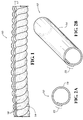
- the figure 1 illustrates an exemplary conduit 10 according to the present invention.
- the pipe 10 preferably comprises a generally tubular or cylindrical wall 14 which is open (split) along a longitudinal axis L1.
- the wall 14 is further preferably corrugated by having multiple corrugations 18.
- the corrugations 18 may advantageously extend relatively to the longitudinal axis helically or annularly, although other shapes may alternatively be employed.
- the conduit 10 is intended to receive bundles of electrical wires or cables, although other objects in particular slender may be housed inside instead. Since the wall 14 is open / split along the axis L1, it is possible to access the beams anywhere along the axis L1. Providing such access may be useful in many circumstances, for example if a repair or replacement of wires or cables, or a connection thereof, is necessary.
- the split wall In the position of use of the pipe, when it receives cables, the split wall is closed on itself, its edges longitudinals on either side of the slot being either abutting or overlapping.
- FIGS. 2A and 2B show the pipe 10 schematically, the undulations 18 not being shown.
- the wall 14 of the corrugated conduit body overlaps to "close" the open conduit.
- the overlap region 22 therefore includes two parallel layers of wall superposition 14 and has twice the thickness of the wall 14. This overlap can reach 180 ° but the preferred angle when electrical wires are installed is between 65 ° and 130 °, in particular between 70 and 110 °, the overall behavior of the pipe in this latter range of overlap being optimal. As this is particularly detailed on the Figure 2A however, line 10 retains a generally circular cross-section in which electrical wires, cables or the like may be introduced. It is possible to access the introduced materials simply by separating the layers of the wall 14 in the overlap region 22.
- the figure 3A details a preferred form of corrugations 18 for the pipe 10.
- the corrugations 18 may be defined by alternating grooves 26 and ribs 30. These grooves 26 and ribs 30 may be relatively to the longitudinal axis of the pipe, helical ( and therefore continuous over a given length of pipe 10, except at the longitudinal opening along the axis L1), annular (and therefore discontinuous over a given length of pipe 10), or have another suitable or desired shape.
- the grooves 26 and the ribs 30 do not necessarily need to be formed or configured as shown on the figure 3A ; instead, for example, they can take the sawtooth form of the figure 3B , the niche form of the figure 3C , or the shape of a sinusoid of the 3D figure . Indeed, those skilled in the art will adapt the shape of the corrugations 18 according to the behavior or the application intended for the pipe 10.
- the figure 3A also shows the central axis L2 of the pipe 10. Since the pipe 10 is curved on the figure 3A the central axis L2 is also curved. This is also true for the figure 4 .
- figure 4 further details an angle ⁇ of a rib 30 with respect to the central axis L2. Assuming that the ribs 30 are formed so that each defines a longitudinal central segment L3, the angle ⁇ can be defined by the intersection of the axis L2 and the segment L3 as shown in FIG. figure 4 .
- the angle ⁇ is preferably in a range from (or in the order of) 40 ° to 140 °, although any angle may be possible in some cases.
- the ribs and the grooves preferably have, according to the length of the pipe, uniform dimensions in width.
- width means the transverse extension to the longitudinal segment L3.
- Line 10 may be manufactured in any suitable manner.
- An example of a manufacturing method uses an elongate open / slit non-corrugated textile body, a corrugated core and a corrugated mold of complementary shape to the corrugated core. Initially, the core is placed inside the textile body. The entire core and body is then placed in a mold configured to complete the corrugations of the core, and the assembly and the mold are heated. and cooled. After the final cooling, the assembly is removed from the mold and the core is removed from the textile body so as to form the pipe 10.
- the textile conduit 10 can be made from any desired yarn made of any type of material or a combination of two or more different materials.
- the materials are in particular chosen from all materials, preferably based on plastic, which can be woven or knitted.
- the conduit 10 is preferably made of a thermoplastic polymer or fabric (e.g., PEEK, meta-aramid, or PPS), both of which are lightweight and flexible.
- the conduit 10 is not limited to aeronautical applications, it may be intended otherwise or in addition to any appropriate field and for any suitable purpose.
- Line 10 may further be of any suitable length, and line lengths may be connected if desired.
- a metallized fabric, a metallic or textile braid, a metallic ribbon, a retractable sheath or any other material of the Goett patent (or other) may be part of the pipe 10 for various functionalities such as electromagnetic protection, protection against friction, etc.
- the pipe 10 may have a small radius of curvature and bend without straining avoiding any separation of the wall 14.
- the conduct of the invention keeps in curves, which are imposed in use, a concave shape at the radii of curvature, in a homogeneous curvature and without presence of pinching and / or flattening of the pipe.
Landscapes
- Engineering & Computer Science (AREA)
- Architecture (AREA)
- Civil Engineering (AREA)
- Structural Engineering (AREA)
- Details Of Indoor Wiring (AREA)
- Rigid Pipes And Flexible Pipes (AREA)
Abstract
Description
La présente invention concerne une conduite ou gaine de protection utilisée en particulier, mais pas exclusivement, pour recevoir des fils/câbles électriques, et concerne plus particulièrement une conduite dont le corps est ouvert/fendu sur au moins une partie de sa longueur.The present invention relates to a conduit or protective sheath used in particular, but not exclusively, to receive electrical wires / cables, and more particularly relates to a pipe whose body is open / split over at least a part of its length.
La gaine ou conduite est destinée à être utilisée en particulier (mais là encore pas exclusivement) dans un aéronef tel qu'un avion.The sheath or pipe is intended to be used in particular (but again not exclusively) in an aircraft such as an airplane.
Le brevet américain
La conduite du type décrit dans ce brevet américain de Goett protège bien les fils électriques ou les câbles logés à l'intérieur. Toutefois, elle est quelque peu encombrante et présente un rayon de courbure relativement grand. Ces caractéristiques compliquent l'installation de la conduite dans certains espaces restreints, ce qui réduit l'utilité globale de la conduite. En outre, dès qu'un fil électrique ou un câble est introduit dans la conduite, il est accessible uniquement aux extrémités de la conduite.The pipe of the type described in this American patent Goett protects the electrical son or cables housed inside. However, it is somewhat bulky and has a relatively large radius of curvature great. These features complicate the installation of the duct in certain restricted spaces, which reduces the overall utility of the duct. In addition, as soon as an electric wire or cable is introduced into the pipe, it is accessible only at the ends of the pipe.
Au contraire de la conduite du brevet américain de Goett, une conduite textile (éloignée des conduites usuelles en matière plastique obtenues par extrusion, telles celle de Goet) dont le corps longitudinal est ouvert permet d'accéder aux fils électriques ou aux câbles introduits à n'importe quel endroit sur sa longueur. Ce type de conduite textile est utilisée notamment à bord des avions à des endroits généralement distincts des conduites PTFE du type celle de Goet, car devant être agencées dans un environnement protégé. Une telle conduite textile peut aussi avoir un rayon de courbure plus petit que la conduite à paroi fermée du brevet Goett, ce qui accroît son utilité dans certaines régions confinées. Cependant, pour obtenir ce rayon de courbure plus petit, cette conduite textile ouverte doit habituellement être tournée sur elle-même/toronnée durant l'installation pour éviter tout écartement de la conduite perpendiculairement à son corps longitudinal, engendrant sinon un manque de protection des câbles. En outre, la torsion gêne, voire empêche, la réouverture de la conduite.In contrast to the conduct of Goett's US patent, a textile conduit (remote from the usual extruded plastic conduits, such as Goet's) whose longitudinal body is open, allows access to electrical wires or cables introduced at the same time. any place on its length. This type of textile pipe is used especially on board airplanes generally separate places PTFE pipes of the type of Goet, because to be arranged in a protected environment. Such a textile conduit may also have a smaller radius of curvature than the Goett patent closed wall conduit, which increases its utility in certain confined areas. However, to obtain this smaller radius of curvature, this open textile conduit must usually be turned on itself / stranded during installation to avoid any separation of the pipe perpendicular to its longitudinal body, otherwise generating a lack of protection cables . In addition, the torsion hinders or even prevents the reopening of the pipe.
Le terme « toronner » dans la suite de la description s'entend comme l'action de tourner, tordre, appliquer une torsion sur le corps de la conduite de protection.The term "strand" in the following description means the action of turning, twist, apply a twist on the body of the protective pipe.
On entend dans la suite de la description par « fil » relatif au matériau constitutif de la conduite, un matériau flexible mono ou multi-filaments, fait, par exemple à partir de polyétheréthercétone (PEEK), de méta-aramide, de polysulfure de phénylène (PPS), ou une combinaison de ceux-ci.In the remainder of the description, the term "wire" refers to the constituent material of the pipe, a single or multi-filament flexible material made, for example from polyetheretherketone (PEEK), meta-aramid, phenylene polysulfide. (PPS), or a combination thereof.
Le terme « textile », tel qu'utilisé ci-après, se réfère à tout dispositif fait de fils multiples assemblés entre eux, qui sont notamment tricotés ou tissés. Le textile peut comprendre, mais pas exclusivement, au moins un fil thermo-formable.The term "textile", as used hereinafter, refers to any device made of multiple yarns joined together, which are especially knitted or woven. The textile may include, but not exclusively, at least one thermoformable yarn.
La présente invention vise à fournir une conduite qui est flexible, qui donne accès aux fils électriques ou aux câbles logés à l'intérieur sur sa longueur, et qui a un petit rayon de courbure. La conduite de l'invention présente en outre un petit rayon de courbure sans torsion, contrairement à une conduite textile à corps ouvert classique. Elle conserve de plus une section transversale généralement circulaire dans laquelle on introduit les fils et les câblages.The present invention aims at providing a pipe which is flexible, which gives access to electrical wires or cables housed therein along its length, and which has a small radius of curvature. The conduct of the invention further has a small radius of curvature without torsion, unlike a conventional open body textile conduit. It also retains a generally circular cross section into which the wires and wiring are introduced.
Selon l'invention, la conduite comprend une paroi flexible ayant d'une façon générale la forme d'un cylindre, la paroi flexible étant fendue selon au moins une certaine longueur et selon un axe longitudinal, caractérisée en ce que la paroi est ondulée. On entend par « ondulée », des formes en saillie de la face externe de la paroi, telles que des cannelures.According to the invention, the pipe comprises a flexible wall having generally the shape of a cylinder, the flexible wall being slit along at least a certain length and along a longitudinal axis, characterized in that the wall is corrugated. The term "corrugated" means shapes protruding from the outer face of the wall, such as flutes.
Les modes de réalisation de l'invention associent des technologies à corps ouvert et à ondulations (cannelures) pour fournir une conduite textile ouverte/fendue et ondulée (cannelée). En combinant des textiles flexibles et des ondulations, le pliage ou le cintrage de la conduite ne génère aucun écartement du matériau. En particulier, dans les courbes prises par la conduite lors de son installation ou au cours de son utilisation, cette configuration au corps fendu et doté d'ondulations (alternance de nervures et de rainures sur la paroi) n'engendre aucune ouverture/bâillement perpendiculairement au corps longitudinal (à la fente longitudinale de la conduite), les câbles restant ainsi protégés. De plus, cela réduit les frictions avec les fils et câbles. En raison de la rigidité résultant des ondulations et l'inutilité de toronner la conduite durant l'installation, la pression exercée par le corps de la conduite sur les fils électriques, en particulier de manière connue entre les points de serrage et de fixation de la conduite, est avantageusement relâchée.Embodiments of the invention combine open-body and corrugated (flute) technologies to provide an open / slotted and corrugated (fluted) textile conduit. By combining flexible textiles and corrugations, the bending or bending of the pipe does not generate any separation of the material. In particular, in the curves taken by the pipe during its installation or during its use, this configuration split body and provided with corrugations (alternation of ribs and grooves on the wall) does not cause any opening / yawning perpendicularly to the longitudinal body (at the longitudinal slot of the pipe), the cables thus remaining protected. In addition, it reduces friction with wires and cables. Due to the rigidity resulting from the corrugations and the need to strand the pipe during the installation, the pressure exerted by the pipe body on the electrical wires, in particular in a known manner between the clamping and fixing points of the pipe. driving, is advantageously relaxed.
La conduite de la présente invention peut être formée d'une façon générale comme un cylindre qui est ouvert/fendu suivant un axe longitudinal. La conduite se ferme en se chevauchant sur elle-même.The conduit of the present invention may be formed generally as a cylinder which is open / split along a longitudinal axis. The pipe closes by overlapping itself.
Ainsi, avantageusement, la paroi flexible se chevauche pour former une région de chevauchement, de préférence le chevauchement correspondant à un angle d'au plus 130°, notamment entre 65 et 130°, en particulier entre et 70 et 110°. Ce chevauchement améliore le maintien en position fermée de la conduite. La région de chevauchement présente ainsi deux fois l'épaisseur d'autres régions, car elle comprend deux couches de matériau contiguës.Thus, advantageously, the flexible wall overlaps to form an overlapping region, preferably the overlap corresponding to an angle of at most 130 °, in particular between 65 and 130 °, in particular between and 70 and 110 °. This overlap improves the maintenance in the closed position of the pipe. The overlap region thus has twice the thickness of other regions because it comprises two contiguous layers of material.
Ce chevauchement engendre par la configuration ondulée de la paroi une coopération mutuelle des nervures et des rainures d'un bord de la fente longitudinale du corps de la conduite avec l'autre bord opposé. Cette coopération mutuelle, sensiblement à la manière de moyens du type mâles-femelles, assure une meilleure prise d'un bord longitudinal sur l'autre de la paroi fendue et garantit un maintien dans le temps d'une surface de contact sur l'autre. La conduite de l'invention n'impose par conséquent pas de la toronner.This overlap generates by the corrugated configuration of the wall a mutual cooperation of the ribs and grooves of one edge of the longitudinal slot of the body of the pipe with the other opposite edge. This mutual cooperation, substantially in the manner of means of the male-female type, ensures better grip of one longitudinal edge on the other of the split wall and ensures a maintenance over time of a contact surface on the other . The conduct of the invention therefore does not impose stranding.
En variante, les bords du corps de la conduite (de chaque côté de la fente) suivant l'axe longitudinal peuvent simplement être contigus, auquel cas il n'y a pas (ou pratiquement pas) de chevauchement.Alternatively, the pipe body edges (on each side of the slot) along the longitudinal axis may simply be contiguous, in which case there is no (or almost no) overlap.
Les ondulations comprennent une alternance de nervures et de rainures.The corrugations comprise alternating ribs and grooves.
Les nervures et les rainures peuvent présenter diverses variantes de formes telles qu'en dents de scie, ou en créneau ou de forme sinusoïdale.The ribs and grooves may have a variety of shapes such as sawtooth, crenellated or sinusoidal.
Les ondulations ne sont pas parallèles à l'axe longitudinal du corps de la conduite. Elles forment un angle par rapport à un axe central de la conduite Chaque nervure définit un segment central longitudinal qui forme avec l'axe central et longitudinal de préférence un angle compris entre (approximativement) 40 et 140°, en particulier de 90°. De plus, les ondulations peuvent s'étendre autour de l'axe longitudinal de manière hélicoïdale ou annulaire.The corrugations are not parallel to the longitudinal axis of the pipe body. They form an angle with respect to a central axis of the duct. Each rib defines a longitudinal central segment which forms with the central and longitudinal axis preferably an angle of between (approximately) 40 and 140 °, in particular 90 °. In addition, the corrugations may extend around the longitudinal axis helically or annularly.
La conduite est faite d'un matériau textile comprenant un ou plusieurs fils en matériau flexible, souple, de préférence à base de matière thermoformable, notamment de matière plastique du type PEEK, méta-aramide, PPS, ou d'une combinaison de ceux-ci.The pipe is made of a textile material comprising one or more wires of flexible, flexible material, preferably based on a thermoformable material, in particular PEEK, meta-aramid, PPS, or a combination of these plastics. this.
La conduite est avantageusement faite à partir d'une matière textile à base de fils tissés et/ou tricotés.The pipe is advantageously made from a textile material based on woven and / or knitted yarns.
La conduite peut intégrer une ou plusieurs fonctionnalités, par exemple par l'ajout de fils spécifiques ou d'une ou de plusieurs couches supplémentaires fonctionnelles. La fonction de blindage électromagnétique peut notamment être associée à la conduite.Driving can integrate one or more functionalities, for example by adding specific threads or one or more additional functional layers. The electromagnetic shielding function can in particular be associated with driving.
La fabrication de la conduite de la présente invention peut utiliser une âme ou un noyau usiné (ou formé d'une autre manière) avec des ondulations correspondant à celles de la conduite finale. Le noyau peut être placé à l'intérieur d'un corps (longiligne) non ondulé et non formé ouvert/fendu suivant un axe longitudinal pour former un ensemble. L'ensemble comprenant la conduite non formée et le noyau, peut alors être placé dans un moule usiné (ou créé d'une autre manière), ondulé de forme complémentaire à celle du noyau ondulé, en vue de former les ondulations du corps. Le moule ainsi que l'ensemble sont ensuite chauffés et refroidis au moins un cycle pour former la conduite en résultant. L'ensemble (la conduite) peut alors être retiré du moule, et le noyau peut être retiré du corps de la conduite ainsi créée, pour préparer la conduite à une utilisation.The manufacture of the conduit of the present invention may utilize a machined (or otherwise formed) core or core with corrugations corresponding to those of the final conduit. The kernel can be placed at the interior of a body (elongated) non-waved and unformed open / split along a longitudinal axis to form an assembly. The assembly comprising the unformed conduit and the core, can then be placed in a machined (or otherwise created), corrugated mold of a shape complementary to that of the corrugated core, to form the undulations of the body. The mold and the assembly are then heated and cooled at least one cycle to form the resulting conduit. The assembly (the pipe) can then be removed from the mold, and the core can be removed from the body of the pipe thus created, to prepare the pipe for use.
La présente invention a donc pour objet sans caractère limitatif et exclusif de proposer une conduite destinée à loger des fils électriques, des câbles et autres objets allongés.The present invention therefore has a non-limiting and exclusive purpose to provide a conduit for housing electrical son, cables and other elongated objects.
La présente invention a pour autre objet, non exclusivement, de proposer une conduite flexible qui donne néanmoins accès à son intérieur sur sa longueur.Another object of the present invention is, not exclusively, to propose a flexible pipe which nevertheless gives access to its interior along its length.
La présente invention a pour autre objet, non exclusivement, de proposer une conduite avec un petit rayon de courbure pouvant être obtenu sans torsion.Another object of the present invention is, not exclusively, to provide a pipe with a small radius of curvature which can be obtained without torsion.
La présente invention a aussi pour objet, non exclusivement, de proposer une conduite dont le corps est à la fois fendu (longitudinalement) et (à surface) ondulée.The present invention also aims, not exclusively, to provide a pipe whose body is both split (longitudinally) and (surface) corrugated.
La présente invention a en outre pour objet, non exclusivement, de proposer une conduite dont les ondulations peuvent former un angle par rapport à un axe central de la conduite.The present invention further relates, not exclusively, to provide a pipe whose corrugations can form an angle relative to a central axis of the pipe.
La présente invention a pour autre objet, non exclusivement, de proposer une conduite dont les ondulations sont formées de manière hélicoïdale ou annulaire, et de préférence orientées entre 40 et 140° par rapport à l'axe central, en particulier à 90°.Another object of the present invention is, not exclusively, to provide a pipe whose corrugations are formed in a helical or annular manner, and preferably oriented between 40 and 140 ° with respect to the central axis, in particular at 90 °.
La présente invention a encore pour autre objet, non exclusivement, de proposer des procédés de fabrication d'une conduite dans lesquels un matériau non ondulé, à corps ouvert/fendu, est moulé avec un noyau ondulé à l'intérieur, le noyau étant retiré par la suite.It is another object of the present invention, not exclusively, to provide methods of manufacturing a pipe in which a non-corrugated, open / split body material is molded with a corrugated core therein, the core being removed thereafter.
L'invention est également relative à l'utilisation d'une telle conduite, qui est par exemple agencée dans un aéronef, notamment un avion.The invention also relates to the use of such a pipe, which is for example arranged in an aircraft, in particular an airplane.
L'invention est aussi relative à un aéronef, en particulier un avion, comprenant :
- a. des moyens pour produire un signal électrique;
- b. des moyens pour recevoir le signal électrique ; et
- c. une conduite pour transporter le signal électrique des moyens de production aux moyens de réception, caractérisé en ce que la conduite comprend une paroi flexible ayant d'une façon générale la forme d'un cylindre, la paroi flexible étant fendue suivant un axe longitudinal, et ondulée.
- at. means for producing an electrical signal;
- b. means for receiving the electrical signal; and
- vs. a pipe for conveying the electrical signal from the production means to the receiving means, characterized in that the pipe comprises a flexible wall generally having the shape of a cylinder, the flexible wall being slotted along a longitudinal axis, and corrugated.
D'autres objets, caractéristiques et avantages de la présente invention apparaîtront dans la description qui suit à l'aide d'exemples uniquement illustratifs et nullement limitatifs de la portée de l'invention, et à partir des illustrations ci-jointes, dans lesquelles :
- La
figure 1 est une vue en perspective d'un exemple de conduite de la présente invention. - La
figure 2A est une vue schématique en élévation de la conduite de lafigure 1 (les ondulations n'étant pas illustrées). - La
figure 2B est une vue en perspective de la version schématisée de la conduite de lafigure 2A . - La
figure 3A est une vue de dessus de la conduite de lafigure 1 . - Les
figures 3B à 3D sont des vues schématiques de variantes de formes d'ondulations différentes de celles de lafigure 3A . - La
figure 4 est une vue de dessus de la conduite de lafigure 1 illustrant un exemple d'orientation angulaire des ondulations par rapport à un axe central de la conduite.
- The
figure 1 is a perspective view of an exemplary conduct of the present invention. - The
Figure 2A is a schematic elevational view of the conduct of thefigure 1 (the undulations are not illustrated). - The
Figure 2B is a perspective view of the schematic version of the conduct of theFigure 2A . - The
figure 3A is a top view of the conduct of thefigure 1 . - The
Figures 3B to 3D are schematic views of different waveform variants different from those of thefigure 3A . - The
figure 4 is a top view of the conduct of thefigure 1 illustrating an example of angular orientation of the corrugations with respect to a central axis of the pipe.
La
En position d'utilisation de la conduite, lorsque celle-ci accueille des câbles, la paroi fendue est refermée sur elle-même, ses bords longitudinaux de part et d'autre de la fente étant soit aboutés, soit se chevauchent.In the position of use of the pipe, when it receives cables, the split wall is closed on itself, its edges longitudinals on either side of the slot being either abutting or overlapping.
Les
La région de chevauchement 22 inclut par conséquent deux couches parallèles de superposition de paroi 14 et possède deux fois l'épaisseur de la paroi 14. Ce chevauchement peut atteindre 180° mais l'angle préféré lorsque des fils électriques sont installés se situe entre 65° et 130°, en particulier entre 70 et 110°, le comportement global de la conduite dans cette dernière plage de chevauchement étant optimal. Comme cela est particulièrement détaillé sur la
La
La
Les nervures et les rainures présentent de préférence, selon la longueur de la conduite, des dimensions uniformes en largeur. On entend par « largeur », l'extension transversale au segment longitudinal L3.The ribs and the grooves preferably have, according to the length of the pipe, uniform dimensions in width. The term "width" means the transverse extension to the longitudinal segment L3.
La conduite 10 peut être fabriquée de n'importe quelle manière appropriée. Un exemple de procédé de fabrication utilise un corps longiligne ouvert/fendu en textile non ondulé, un noyau ondulé et un moule ondulé de forme complémentaire au noyau ondulé. Au départ, le noyau est placé à l'intérieur du corps en textile. L'ensemble du noyau et du corps est alors placé dans un moule configuré pour compléter les ondulations du noyau, et l'ensemble ainsi que le moule sont chauffés et refroidis. Après le refroidissement final, l'ensemble est retiré du moule et le noyau est retiré du corps textile de manière à former la conduite 10.
La conduite 10 en textile peut être fabriquée à partir de n'importe quel fil souhaité réalisé dans tout type de matériau ou dans une combinaison de deux ou plusieurs matériaux distincts. Les matériaux sont notamment choisis parmi toutes matières, de préférence à base de matière plastique, aptes à être tissées ou tricotées. Pour les applications aéronautiques, la conduite 10 est de préférence constituée d'un polymère ou d'un tissu thermoplastique (par exemple PEEK, méta-aramide, ou PPS), qui sont tous les deux légers et flexibles. La conduite 10 ne se limite cependant pas aux applications aéronautiques, elle peut être destinée au contraire ou en outre à tout domaine approprié et à toute fin appropriée.The
La conduite 10 peut de plus présenter toute longueur adaptée, et des longueurs de conduite 10 peuvent être raccordées si on le souhaite. Un tissu métallisé, une tresse métallique ou textile, un ruban métallique, une gaine rétractable ou tout autre matériau du brevet Goett (ou autre) peut faire partie de la conduite 10 pour des fonctionnalités divers telles qu'une protection électromagnétique, une protection contre les frottements, etc...
Par sa configuration, la conduite 10 peut posséder un petit rayon de courbure et se plier sans se toronner en évitant tout écartement de la paroi 14. En outre, la conduite de l'invention garde dans les courbes, qui sont imposées en utilisation, une forme concave au niveau des rayons de courbure, selon une courbure homogène et sans présence de pincement et/ou d'aplatissement de la conduite.By its configuration, the
Ce qui précède est fourni uniquement en vue d'illustrer, d'expliquer et de décrire des modes de réalisation de la présente invention. Des modifications et des adaptations de ces modes de réalisation apparaîtront à l'homme du métier et pourront être apportées sans s'écarter de la portée ou de l'esprit de l'invention. L'intégralité du contenu du brevet Goett est intégrée aux présentes par cette référence.The foregoing is provided solely for the purpose of illustrating, explaining, and describing embodiments of the present invention. Modifications and adaptations of these embodiments will be apparent to those skilled in the art and may be made without departing from the scope or spirit of the invention. The entire contents of the Goett patent are incorporated herein by this reference.
Claims (12)
Applications Claiming Priority (1)
| Application Number | Priority Date | Filing Date | Title |
|---|---|---|---|
| US201161497164P | 2011-06-15 | 2011-06-15 |
Publications (1)
| Publication Number | Publication Date |
|---|---|
| EP2535991A1 true EP2535991A1 (en) | 2012-12-19 |
Family
ID=46508232
Family Applications (1)
| Application Number | Title | Priority Date | Filing Date |
|---|---|---|---|
| EP12171675A Withdrawn EP2535991A1 (en) | 2011-06-15 | 2012-06-12 | Protective pipe, in particular for housing electrical cables |
Country Status (3)
| Country | Link |
|---|---|
| US (1) | US20120318397A1 (en) |
| EP (1) | EP2535991A1 (en) |
| FR (1) | FR2976742A1 (en) |
Cited By (1)
| Publication number | Priority date | Publication date | Assignee | Title |
|---|---|---|---|---|
| WO2015024289A1 (en) * | 2013-08-19 | 2015-02-26 | 深圳酷卡仕科技有限公司 | Tooth-form support |
Families Citing this family (3)
| Publication number | Priority date | Publication date | Assignee | Title |
|---|---|---|---|---|
| AU2014354752B2 (en) * | 2013-11-27 | 2018-12-13 | Patrick L. Chapman | Integration of microinverter with photovoltaic module |
| GB2595207A (en) * | 2020-05-04 | 2021-11-24 | Stirling Moulded Composites Ltd | Long article management conduit and method for producing the same |
| US11952110B1 (en) * | 2021-08-24 | 2024-04-09 | Sifly Aviation, Inc. | Electric rotorcraft cyclic control system |
Citations (6)
| Publication number | Priority date | Publication date | Assignee | Title |
|---|---|---|---|---|
| WO1995013495A1 (en) * | 1993-11-11 | 1995-05-18 | Bentley Harris Manufacturing Co. | Integrally flanged flexible sleeve |
| GB2336475A (en) * | 1998-04-18 | 1999-10-20 | T & N Technology Ltd | Flexible protective sleeve |
| US6563045B2 (en) | 1998-03-26 | 2003-05-13 | Icore International, Inc. | Lightweight shielded conduit |
| EP1775811A1 (en) * | 2004-08-05 | 2007-04-18 | Relats, S.A. | Flexible protective corrugated tube |
| FR2899838A1 (en) * | 2006-04-18 | 2007-10-19 | Sofanou Sa | METHOD AND DEVICE FOR MANUFACTURING AN ASSEMBLY OF TWO ANNELED SLEEVES DETACHABLE FROM EACH OTHER TO REALIZE A SINGLE YARN SHEATH |
| EP2131466A1 (en) * | 2007-03-29 | 2009-12-09 | Relats, S.A. | Protective sheath for cables, tubes and the like |
Family Cites Families (17)
| Publication number | Priority date | Publication date | Assignee | Title |
|---|---|---|---|---|
| US3466210A (en) * | 1966-01-10 | 1969-09-09 | Richard C Wareham | Method of forming a heat shrinkable tubular sleeve and bonding same to a tubular member |
| DE1945250U (en) * | 1966-03-07 | 1966-09-01 | Suomen Kaapelitehdas Osakeyhti | GUTTER FOR ELECTRIC CABLES. |
| US3857415A (en) * | 1970-09-15 | 1974-12-31 | Everflex Prod Inc | Reinforced convoluted tubing of polytetrafluoroethylene |
| US4384167A (en) * | 1982-02-19 | 1983-05-17 | General Motors Corporation | Break-out protector and wiring harness including same |
| US4929478A (en) * | 1988-06-17 | 1990-05-29 | The Bentley-Harris Manufacturing Company | Protective fabric sleeves |
| US4970351A (en) * | 1990-03-02 | 1990-11-13 | United Techologies Automotive, Inc. | Wiring harness conduit |
| US5186992A (en) * | 1990-03-12 | 1993-02-16 | The Bentley-Harris Manufacturing Company | Braided product and method of making same |
| US5413149A (en) * | 1991-11-05 | 1995-05-09 | The Bentley-Harris Manufacturing Company | Shaped fabric products and methods of making same |
| US5613522A (en) * | 1991-11-05 | 1997-03-25 | Bentley-Harris Inc. | Shaped fabric products |
| US5505117A (en) * | 1992-08-18 | 1996-04-09 | Dunlap; Daryl S. | Braided sleeve |
| US5485870A (en) * | 1994-12-05 | 1996-01-23 | Kraik; Newell P. | Wire wrapped composite spiral hose and method |
| US6433273B1 (en) * | 2000-10-20 | 2002-08-13 | The Zippertubing Co. | Heat-shielding jacket |
| AU2002326521A1 (en) * | 2001-08-09 | 2003-02-24 | Federal-Mogul Powertrain, Inc. | Damped flexible protective sleeving |
| US7395680B2 (en) * | 2004-07-20 | 2008-07-08 | Federal Mogul Worldwide, Inc. | Self-curling knitted sleeve and method of fabrication |
| WO2006014694A2 (en) * | 2004-07-20 | 2006-02-09 | Federal-Mogul World Wide, Inc. | Self-curling sleeve |
| DE102006062545B4 (en) * | 2006-12-29 | 2008-09-18 | Flexa Gmbh & Co. Produktion Und Vertrieb Kg | Auxiliary tool, set with an auxiliary tool, a protective tube and a closure element and arrangement with a supply of a protective tube and an auxiliary tool |
| US8925592B2 (en) * | 2009-06-11 | 2015-01-06 | Federal-Mogul Powertrain, Inc. | Flexible, abrasion resistant textile sleeve and method of construction thereof |
-
2012
- 2012-06-12 US US13/494,043 patent/US20120318397A1/en not_active Abandoned
- 2012-06-12 FR FR1255483A patent/FR2976742A1/en not_active Withdrawn
- 2012-06-12 EP EP12171675A patent/EP2535991A1/en not_active Withdrawn
Patent Citations (6)
| Publication number | Priority date | Publication date | Assignee | Title |
|---|---|---|---|---|
| WO1995013495A1 (en) * | 1993-11-11 | 1995-05-18 | Bentley Harris Manufacturing Co. | Integrally flanged flexible sleeve |
| US6563045B2 (en) | 1998-03-26 | 2003-05-13 | Icore International, Inc. | Lightweight shielded conduit |
| GB2336475A (en) * | 1998-04-18 | 1999-10-20 | T & N Technology Ltd | Flexible protective sleeve |
| EP1775811A1 (en) * | 2004-08-05 | 2007-04-18 | Relats, S.A. | Flexible protective corrugated tube |
| FR2899838A1 (en) * | 2006-04-18 | 2007-10-19 | Sofanou Sa | METHOD AND DEVICE FOR MANUFACTURING AN ASSEMBLY OF TWO ANNELED SLEEVES DETACHABLE FROM EACH OTHER TO REALIZE A SINGLE YARN SHEATH |
| EP2131466A1 (en) * | 2007-03-29 | 2009-12-09 | Relats, S.A. | Protective sheath for cables, tubes and the like |
Cited By (1)
| Publication number | Priority date | Publication date | Assignee | Title |
|---|---|---|---|---|
| WO2015024289A1 (en) * | 2013-08-19 | 2015-02-26 | 深圳酷卡仕科技有限公司 | Tooth-form support |
Also Published As
| Publication number | Publication date |
|---|---|
| FR2976742A1 (en) | 2012-12-21 |
| US20120318397A1 (en) | 2012-12-20 |
Similar Documents
| Publication | Publication Date | Title |
|---|---|---|
| EP2535991A1 (en) | Protective pipe, in particular for housing electrical cables | |
| EP2805393B1 (en) | Protective sheath, in particular for electric cables, and method for manufacturing same | |
| WO1999005441A1 (en) | Flexible conduit, such as pipe for medical or surgical use | |
| FR2899838A1 (en) | METHOD AND DEVICE FOR MANUFACTURING AN ASSEMBLY OF TWO ANNELED SLEEVES DETACHABLE FROM EACH OTHER TO REALIZE A SINGLE YARN SHEATH | |
| JP2013241954A (en) | Pipe joint | |
| FR2833679A1 (en) | Re-coverable sheath for electric wires, or conduits in automotive vehicles, can be re-closed by using adhesive members | |
| EP1931235B1 (en) | Grommet | |
| EP1382102A1 (en) | Protective sheath comprising a longitudinal flexible material strip and method for producing said sheath | |
| EP1742318A1 (en) | Tube support for cold shrinkable sleeve for electrical cable junction | |
| FR3068998A1 (en) | SIMPLIFIED AIR SEALING SYSTEM FOR A DOUBLE WALL OF AN INSULATION. | |
| FR2934427A1 (en) | CLOSETABLE LID OF CHUTE, AND CHUTE PROVIDED WITH SUCH AN ENCLICABLE COVER | |
| EP3717829A1 (en) | Bodywork component having an optical element fitted by snap-fastening | |
| WO2018073497A1 (en) | Protective sheath in particular intended for housing electrical cables | |
| FR2722820A1 (en) | Hollow metal fencing post | |
| EP0291418A1 (en) | Plastic extruded tube | |
| EP3129566B1 (en) | Fitting device for receiving the end of a rod forming a holding element for a construction element around which the holding element is clamped | |
| FR2513449A1 (en) | Mounting clip for bundles of small electronic cables - uses flexible band with compressible inner lining formed with inward facing serrations cooperating with cable dia. | |
| FR2906342A3 (en) | Inlet for ringed conduit, has elastically flexible pieces radially spaced, when axial force is applied on pieces under pressure of ringed conduit and including lip that is resistant to tearing off of conduit by being supported on ring | |
| EP2597222B1 (en) | False wall comprising stretched cloth joined by a separation rail | |
| EP2113468B1 (en) | Flexible protective sheath for a windscreen | |
| FR2769967A1 (en) | Combination flex for steam smoothing iron | |
| FR2920855A1 (en) | End fitting mounting method for reinforced thermoplastic pipe, involves folding free ends of wires against external polymeric sheath before covering end of pipe with cylindrical cover to fixedly maintain free ends between sheath and cover | |
| FR3008439A1 (en) | CLADDING BLADE | |
| FR3039299A1 (en) | RADIOIDENTIFICATION DEVICE FOR A TUBULAR-SHAPED IDENTIFIER ELEMENT IN A BINDING ENVIRONMENT | |
| FR3088770A1 (en) | PROTECTION SHEATH OF TORON |
Legal Events
| Date | Code | Title | Description |
|---|---|---|---|
| PUAI | Public reference made under article 153(3) epc to a published international application that has entered the european phase |
Free format text: ORIGINAL CODE: 0009012 |
|
| AK | Designated contracting states |
Kind code of ref document: A1 Designated state(s): AL AT BE BG CH CY CZ DE DK EE ES FI FR GB GR HR HU IE IS IT LI LT LU LV MC MK MT NL NO PL PT RO RS SE SI SK SM TR |
|
| AX | Request for extension of the european patent |
Extension state: BA ME |
|
| 17P | Request for examination filed |
Effective date: 20130617 |
|
| RBV | Designated contracting states (corrected) |
Designated state(s): AL AT BE BG CH CY CZ DE DK EE ES FI FR GB GR HR HU IE IS IT LI LT LU LV MC MK MT NL NO PL PT RO RS SE SI SK SM TR |
|
| STAA | Information on the status of an ep patent application or granted ep patent |
Free format text: STATUS: THE APPLICATION IS DEEMED TO BE WITHDRAWN |
|
| 18D | Application deemed to be withdrawn |
Effective date: 20160105 |