EP2535652B1 - Air conditioner - Google Patents
Air conditioner Download PDFInfo
- Publication number
- EP2535652B1 EP2535652B1 EP10845660.9A EP10845660A EP2535652B1 EP 2535652 B1 EP2535652 B1 EP 2535652B1 EP 10845660 A EP10845660 A EP 10845660A EP 2535652 B1 EP2535652 B1 EP 2535652B1
- Authority
- EP
- European Patent Office
- Prior art keywords
- heat
- heat medium
- refrigerant
- heat exchanger
- air
- Prior art date
- Legal status (The legal status is an assumption and is not a legal conclusion. Google has not performed a legal analysis and makes no representation as to the accuracy of the status listed.)
- Active
Links
- 239000003507 refrigerant Substances 0.000 claims description 341
- 238000010438 heat treatment Methods 0.000 claims description 115
- 238000004378 air conditioning Methods 0.000 claims description 97
- 238000001816 cooling Methods 0.000 claims description 75
- 238000010257 thawing Methods 0.000 claims description 69
- 238000011084 recovery Methods 0.000 claims description 12
- 239000007789 gas Substances 0.000 description 26
- 239000007788 liquid Substances 0.000 description 18
- 238000010586 diagram Methods 0.000 description 16
- XLYOFNOQVPJJNP-UHFFFAOYSA-N water Substances O XLYOFNOQVPJJNP-UHFFFAOYSA-N 0.000 description 13
- 238000001704 evaporation Methods 0.000 description 8
- CURLTUGMZLYLDI-UHFFFAOYSA-N Carbon dioxide Chemical compound O=C=O CURLTUGMZLYLDI-UHFFFAOYSA-N 0.000 description 5
- 229910002092 carbon dioxide Inorganic materials 0.000 description 4
- 239000001569 carbon dioxide Substances 0.000 description 4
- 238000010276 construction Methods 0.000 description 4
- 238000011144 upstream manufacturing Methods 0.000 description 4
- 230000002528 anti-freeze Effects 0.000 description 3
- 230000000694 effects Effects 0.000 description 3
- 238000009434 installation Methods 0.000 description 3
- 239000000203 mixture Substances 0.000 description 3
- ATUOYWHBWRKTHZ-UHFFFAOYSA-N Propane Chemical compound CCC ATUOYWHBWRKTHZ-UHFFFAOYSA-N 0.000 description 2
- 239000012267 brine Substances 0.000 description 2
- 230000001143 conditioned effect Effects 0.000 description 2
- 238000001514 detection method Methods 0.000 description 2
- 230000008014 freezing Effects 0.000 description 2
- 238000007710 freezing Methods 0.000 description 2
- 230000006872 improvement Effects 0.000 description 2
- 239000011259 mixed solution Substances 0.000 description 2
- 230000000717 retained effect Effects 0.000 description 2
- HPALAKNZSZLMCH-UHFFFAOYSA-M sodium;chloride;hydrate Chemical compound O.[Na+].[Cl-] HPALAKNZSZLMCH-UHFFFAOYSA-M 0.000 description 2
- 239000000654 additive Substances 0.000 description 1
- 230000000996 additive effect Effects 0.000 description 1
- 230000003466 anti-cipated effect Effects 0.000 description 1
- 230000008859 change Effects 0.000 description 1
- 238000009833 condensation Methods 0.000 description 1
- 230000005494 condensation Effects 0.000 description 1
- 230000008020 evaporation Effects 0.000 description 1
- 230000008018 melting Effects 0.000 description 1
- 238000002844 melting Methods 0.000 description 1
- 230000002265 prevention Effects 0.000 description 1
- 239000001294 propane Substances 0.000 description 1
- 230000005855 radiation Effects 0.000 description 1
- 230000009467 reduction Effects 0.000 description 1
- 238000005057 refrigeration Methods 0.000 description 1
- 239000000243 solution Substances 0.000 description 1
- 239000000126 substance Substances 0.000 description 1
- 239000000725 suspension Substances 0.000 description 1
- 238000009423 ventilation Methods 0.000 description 1
- 238000010792 warming Methods 0.000 description 1
- 239000002918 waste heat Substances 0.000 description 1
- 239000002699 waste material Substances 0.000 description 1
Images


Classifications
-
- F—MECHANICAL ENGINEERING; LIGHTING; HEATING; WEAPONS; BLASTING
- F24—HEATING; RANGES; VENTILATING
- F24F—AIR-CONDITIONING; AIR-HUMIDIFICATION; VENTILATION; USE OF AIR CURRENTS FOR SCREENING
- F24F3/00—Air-conditioning systems in which conditioned primary air is supplied from one or more central stations to distributing units in the rooms or spaces where it may receive secondary treatment; Apparatus specially designed for such systems
- F24F3/06—Air-conditioning systems in which conditioned primary air is supplied from one or more central stations to distributing units in the rooms or spaces where it may receive secondary treatment; Apparatus specially designed for such systems characterised by the arrangements for the supply of heat-exchange fluid for the subsequent treatment of primary air in the room units
-
- F—MECHANICAL ENGINEERING; LIGHTING; HEATING; WEAPONS; BLASTING
- F24—HEATING; RANGES; VENTILATING
- F24F—AIR-CONDITIONING; AIR-HUMIDIFICATION; VENTILATION; USE OF AIR CURRENTS FOR SCREENING
- F24F11/00—Control or safety arrangements
- F24F11/89—Arrangement or mounting of control or safety devices
-
- F—MECHANICAL ENGINEERING; LIGHTING; HEATING; WEAPONS; BLASTING
- F25—REFRIGERATION OR COOLING; COMBINED HEATING AND REFRIGERATION SYSTEMS; HEAT PUMP SYSTEMS; MANUFACTURE OR STORAGE OF ICE; LIQUEFACTION SOLIDIFICATION OF GASES
- F25B—REFRIGERATION MACHINES, PLANTS OR SYSTEMS; COMBINED HEATING AND REFRIGERATION SYSTEMS; HEAT PUMP SYSTEMS
- F25B13/00—Compression machines, plants or systems, with reversible cycle
-
- F—MECHANICAL ENGINEERING; LIGHTING; HEATING; WEAPONS; BLASTING
- F25—REFRIGERATION OR COOLING; COMBINED HEATING AND REFRIGERATION SYSTEMS; HEAT PUMP SYSTEMS; MANUFACTURE OR STORAGE OF ICE; LIQUEFACTION SOLIDIFICATION OF GASES
- F25B—REFRIGERATION MACHINES, PLANTS OR SYSTEMS; COMBINED HEATING AND REFRIGERATION SYSTEMS; HEAT PUMP SYSTEMS
- F25B25/00—Machines, plants or systems, using a combination of modes of operation covered by two or more of the groups F25B1/00 - F25B23/00
- F25B25/005—Machines, plants or systems, using a combination of modes of operation covered by two or more of the groups F25B1/00 - F25B23/00 using primary and secondary systems
-
- F—MECHANICAL ENGINEERING; LIGHTING; HEATING; WEAPONS; BLASTING
- F25—REFRIGERATION OR COOLING; COMBINED HEATING AND REFRIGERATION SYSTEMS; HEAT PUMP SYSTEMS; MANUFACTURE OR STORAGE OF ICE; LIQUEFACTION SOLIDIFICATION OF GASES
- F25B—REFRIGERATION MACHINES, PLANTS OR SYSTEMS; COMBINED HEATING AND REFRIGERATION SYSTEMS; HEAT PUMP SYSTEMS
- F25B47/00—Arrangements for preventing or removing deposits or corrosion, not provided for in another subclass
- F25B47/02—Defrosting cycles
- F25B47/022—Defrosting cycles hot gas defrosting
- F25B47/025—Defrosting cycles hot gas defrosting by reversing the cycle
-
- F—MECHANICAL ENGINEERING; LIGHTING; HEATING; WEAPONS; BLASTING
- F24—HEATING; RANGES; VENTILATING
- F24F—AIR-CONDITIONING; AIR-HUMIDIFICATION; VENTILATION; USE OF AIR CURRENTS FOR SCREENING
- F24F11/00—Control or safety arrangements
- F24F11/30—Control or safety arrangements for purposes related to the operation of the system, e.g. for safety or monitoring
- F24F11/41—Defrosting; Preventing freezing
-
- F—MECHANICAL ENGINEERING; LIGHTING; HEATING; WEAPONS; BLASTING
- F24—HEATING; RANGES; VENTILATING
- F24F—AIR-CONDITIONING; AIR-HUMIDIFICATION; VENTILATION; USE OF AIR CURRENTS FOR SCREENING
- F24F2221/00—Details or features not otherwise provided for
- F24F2221/54—Heating and cooling, simultaneously or alternatively
-
- F—MECHANICAL ENGINEERING; LIGHTING; HEATING; WEAPONS; BLASTING
- F25—REFRIGERATION OR COOLING; COMBINED HEATING AND REFRIGERATION SYSTEMS; HEAT PUMP SYSTEMS; MANUFACTURE OR STORAGE OF ICE; LIQUEFACTION SOLIDIFICATION OF GASES
- F25B—REFRIGERATION MACHINES, PLANTS OR SYSTEMS; COMBINED HEATING AND REFRIGERATION SYSTEMS; HEAT PUMP SYSTEMS
- F25B2313/00—Compression machines, plants or systems with reversible cycle not otherwise provided for
- F25B2313/023—Compression machines, plants or systems with reversible cycle not otherwise provided for using multiple indoor units
- F25B2313/0231—Compression machines, plants or systems with reversible cycle not otherwise provided for using multiple indoor units with simultaneous cooling and heating
-
- F—MECHANICAL ENGINEERING; LIGHTING; HEATING; WEAPONS; BLASTING
- F25—REFRIGERATION OR COOLING; COMBINED HEATING AND REFRIGERATION SYSTEMS; HEAT PUMP SYSTEMS; MANUFACTURE OR STORAGE OF ICE; LIQUEFACTION SOLIDIFICATION OF GASES
- F25B—REFRIGERATION MACHINES, PLANTS OR SYSTEMS; COMBINED HEATING AND REFRIGERATION SYSTEMS; HEAT PUMP SYSTEMS
- F25B2313/00—Compression machines, plants or systems with reversible cycle not otherwise provided for
- F25B2313/023—Compression machines, plants or systems with reversible cycle not otherwise provided for using multiple indoor units
- F25B2313/0232—Compression machines, plants or systems with reversible cycle not otherwise provided for using multiple indoor units with bypasses
- F25B2313/02322—Compression machines, plants or systems with reversible cycle not otherwise provided for using multiple indoor units with bypasses during defrosting
-
- F—MECHANICAL ENGINEERING; LIGHTING; HEATING; WEAPONS; BLASTING
- F25—REFRIGERATION OR COOLING; COMBINED HEATING AND REFRIGERATION SYSTEMS; HEAT PUMP SYSTEMS; MANUFACTURE OR STORAGE OF ICE; LIQUEFACTION SOLIDIFICATION OF GASES
- F25B—REFRIGERATION MACHINES, PLANTS OR SYSTEMS; COMBINED HEATING AND REFRIGERATION SYSTEMS; HEAT PUMP SYSTEMS
- F25B2313/00—Compression machines, plants or systems with reversible cycle not otherwise provided for
- F25B2313/027—Compression machines, plants or systems with reversible cycle not otherwise provided for characterised by the reversing means
- F25B2313/0272—Compression machines, plants or systems with reversible cycle not otherwise provided for characterised by the reversing means using bridge circuits of one-way valves
-
- F—MECHANICAL ENGINEERING; LIGHTING; HEATING; WEAPONS; BLASTING
- F25—REFRIGERATION OR COOLING; COMBINED HEATING AND REFRIGERATION SYSTEMS; HEAT PUMP SYSTEMS; MANUFACTURE OR STORAGE OF ICE; LIQUEFACTION SOLIDIFICATION OF GASES
- F25B—REFRIGERATION MACHINES, PLANTS OR SYSTEMS; COMBINED HEATING AND REFRIGERATION SYSTEMS; HEAT PUMP SYSTEMS
- F25B2313/00—Compression machines, plants or systems with reversible cycle not otherwise provided for
- F25B2313/027—Compression machines, plants or systems with reversible cycle not otherwise provided for characterised by the reversing means
- F25B2313/02732—Compression machines, plants or systems with reversible cycle not otherwise provided for characterised by the reversing means using two three-way valves
-
- F—MECHANICAL ENGINEERING; LIGHTING; HEATING; WEAPONS; BLASTING
- F25—REFRIGERATION OR COOLING; COMBINED HEATING AND REFRIGERATION SYSTEMS; HEAT PUMP SYSTEMS; MANUFACTURE OR STORAGE OF ICE; LIQUEFACTION SOLIDIFICATION OF GASES
- F25B—REFRIGERATION MACHINES, PLANTS OR SYSTEMS; COMBINED HEATING AND REFRIGERATION SYSTEMS; HEAT PUMP SYSTEMS
- F25B2313/00—Compression machines, plants or systems with reversible cycle not otherwise provided for
- F25B2313/027—Compression machines, plants or systems with reversible cycle not otherwise provided for characterised by the reversing means
- F25B2313/02741—Compression machines, plants or systems with reversible cycle not otherwise provided for characterised by the reversing means using one four-way valve
-
- F—MECHANICAL ENGINEERING; LIGHTING; HEATING; WEAPONS; BLASTING
- F25—REFRIGERATION OR COOLING; COMBINED HEATING AND REFRIGERATION SYSTEMS; HEAT PUMP SYSTEMS; MANUFACTURE OR STORAGE OF ICE; LIQUEFACTION SOLIDIFICATION OF GASES
- F25B—REFRIGERATION MACHINES, PLANTS OR SYSTEMS; COMBINED HEATING AND REFRIGERATION SYSTEMS; HEAT PUMP SYSTEMS
- F25B2600/00—Control issues
- F25B2600/25—Control of valves
- F25B2600/2513—Expansion valves
Definitions
- the present invention relates to an air-conditioning apparatus that is applied to, for example, a multi-air-conditioning apparatus for a building.
- a refrigerant is circulated between an outdoor unit, which is a heat source unit disposed, for example, outside a structure, and indoor units disposed in rooms in the structure.
- the refrigerant transfers heat or removes heat to heat or cool air, thus heating or cooling an air conditioned space through the heated or cooled air.
- Hydrofluorocarbon (HFC) based refrigerants are often used as the refrigerant, for example.
- cooling energy or heating energy is generated in a heat source unit disposed outside a structure.
- Water, antifreeze, or the like is heated or cooled by a heat exchanger disposed in an outdoor unit and it is carried to an indoor unit, such as a fan coil unit or a panel heater, to perform heating or cooling (refer to Patent Literature 1, for example).
- a heat recovery chiller that connects a heat source unit to each indoor unit with four water pipings arranged therebetween, supplies cooled and heated water or the like simultaneously, and allows the cooling and heating in the indoor units to be selected freely (refer to Patent Literature 2, for example).
- WO2009/133640 discloses the preamble of claim 1.
- an air-conditioning apparatus of the related art such as a multi-air-conditioning apparatus for a building
- a refrigerant leakage to, for example, an indoor space since the refrigerant is circulated to an indoor unit.
- the refrigerant does not pass through the indoor unit.
- the heat medium needs to be heated or cooled in a heat source unit disposed outside a structure, and needs to be carried to the indoor unit side. Accordingly, a circulation path of the heat medium becomes long.
- an air-conditioning apparatus of the related art such as a multi-air-conditioning apparatus for a building
- a defrosting operation mode to remove frost attached to a heat source side heat exchanger.
- the defrosting operation mode of such an air-conditioning apparatus since the defrosting is carried out by providing the heat source side heat exchanger with merely a heat capacity that had been retained in a refrigerant that had been conveyed to an indoor unit performing a heating operation and a heat capacity that had been retained in an actuator in a refrigerant conveying passage, it takes a long time until the defrosting is completed.
- the heating operation in the indoor space is suspended, the temperature of the indoor air is lowered, thus, disadvantageously undermining performance of a comfortable heating operation.
- the present invention has been made to overcome the above-described disadvantages and provides an air-conditioning apparatus capable of achieving energy saving.
- the invention further provides an air-conditioning apparatus capable of achieving improvement of safety by not allowing refrigerant to circulate in or near an indoor unit.
- the invention further provides an air-conditioning apparatus that is capable of reducing the number of pipings connecting an outdoor unit to a branch unit (heat medium relay unit) or the branch unit to an indoor unit, and improving ease of construction as well as allowing efficient defrosting operation to be performed, thus improving energy efficiency.
- the pipings in which the heat medium circulates can be shortened and small conveyance power is required, and thus, safety is increased and energy is saved. Further, according to the air-conditioning apparatus of the invention, efficient defrosting operation can be carried out and further energy saving can be achieved.
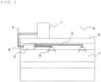
- Fig. 1 is a schematic diagram illustrating an exemplary installation of an air-conditioning apparatus according to Embodiment of the invention.
- This air-conditioning apparatus uses refrigeration cycles (a refrigerant circuit A and a heat medium circuit B) in which refrigerants (a heat source side refrigerant and a heat medium) circulate such that a cooling mode or a heating mode can be freely selected as its operation mode in each indoor unit.
- refrigerants a heat source side refrigerant and a heat medium
- the air-conditioning apparatus includes a single outdoor unit 1, functioning as a heat source unit, a plurality of indoor units 3, and a relay unit 2 disposed between the outdoor unit 1 and the indoor units 3.
- the relay unit 2 exchanges heat between the heat source side refrigerant and the heat medium.
- the outdoor unit 1 and the relay unit 2 are connected with refrigerant pipings 4 through which the heat source side refrigerant flows.
- the relay unit 2 and each indoor unit 3 are connected with pipings 5 (heat medium pipings) through which the heat medium flows. Cooling energy or heating energy generated in the outdoor unit 1 is delivered through the relay unit 2 to the indoor units 3.
- the outdoor unit 1 is typically disposed in an outdoor space 6 that is a space (e.g., a roof) outside a structure 9, such as a building, and is configured to supply cooling energy or heating energy through the relay unit 2 to the indoor units 3.
- Each indoor unit 3 is disposed at a position that can supply cooling air or heating air to an indoor space 7, which is a space (e.g., a living room) inside the structure 9, and supplies air for cooling or air for heating to the indoor space 7 that is an air conditioned space.
- the relay unit 2 is configured so that it can be disposed in a space different from the outdoor space 6 and the indoor space 7, (for example, a common space or a space above a ceiling in the structure 9, hereinafter, simply referred to as a "space 8").
- the relay unit 2 is connected to the outdoor unit 1 and the indoor units 3 with refrigerant pipings 4 and pipings 5, respectively, and conveys cooling energy or heating energy supplied from the outdoor unit 1 to the indoor units 3.
- the outdoor unit 1 is connected to the relay unit 2 using two refrigerant pipings 4, and the relay unit 2 is connected to each indoor unit 3 using two pipings 5.
- each of the units (the outdoor unit 1, the indoor units 3, and the relay unit 2) is connected using two pipings (the refrigerant pipings 4 or the pipings 5), thus construction is facilitated.
- the heat source side refrigerant is conveyed from the outdoor unit 1 to the relay unit 2 through the refrigerant piping 4.
- the heat source side refrigerant that has been conveyed to the relay unit 2 exchanges heat with the heat medium in a heat exchanger related to heat medium (described subsequently) in the relay unit 2 and transfers the heating energy or the cooling energy to the heat medium.
- the heating energy or the cooling energy stored in the heat medium is conveyed with a pump (described subsequently) to the indoor units 3 through the pipings 5.
- the heat medium that has been conveyed to the indoor units 3 is used in the heating operation or the cooling operation for the indoor space 7.
- FIG. 1 an exemplary state in which the relay unit 2 is disposed in the space 8, which is in the structure 9 but is a separate space to the indoor space 7, as a different casing from the outdoor unit 1 and the indoor units 3 is illustrated.
- the relay unit 2 can be disposed in other spaces, such as a common space where an elevator or the like is installed.
- Fig. 1 illustrates a case in which the indoor units 3 are of a ceiling-mounted cassette type, the indoor units are not limited to this type and, for example, a ceiling-concealed type, a ceiling-suspended type, or any type of indoor unit may be used as long as the unit can blow out heating air or cooling air into the indoor space 7 directly or through a duct or the like.
- Fig. 1 illustrates a case in which the outdoor unit 1 is disposed in the outdoor space 6.
- the outdoor unit 1 may be disposed in an enclosed space, for example, a machine room with a ventilation opening, may be disposed inside the structure 9 as long as waste heat can be exhausted through an exhaust duct to the outside of the structure 9, or may be disposed inside the structure 9 when the used outdoor unit 1 is of a water-cooled type. Even when the outdoor unit 1 is disposed in such a place, no problem in particular will occur.
- the relay unit 2 can be disposed near the outdoor unit 1.
- the numbers of connected outdoor unit 1, indoor units 3, and relay unit 2 are not limited to those illustrated in Fig. 1 . The numbers thereof can be determined in accordance with the structure 9 where the air-conditioning apparatus according to Embodiment is installed.
- a heat exchanger related to heat medium 25a or a heat exchanger related to heat medium 25b While a heat exchanger related to heat medium 25a or a heat exchanger related to heat medium 25b is operating for heating, a refrigerant that typically changes between two phases is condensed and liquefied and a refrigerant that turns into a supercritical state, such as CO 2 , is cooled in the supercritical state. As for the rest, either of the refrigerant acts in the same manner and offers the same advantages.
- the heat medium for example, brine (antifreeze), water, a mixed solution of brine and water, or a mixed solution of water and an additive with high anticorrosive effect can be used.
- brine antifreeze
- water a mixed solution of brine and water
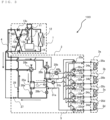
- Fig. 2 is a schematic circuit diagram illustrating an exemplary circuit configuration of the air-conditioning apparatus (hereinafter, referred to as an "air-conditioning apparatus 100") according to Embodiment of the invention.
- the detailed circuit configuration of the air-conditioning apparatus 100 will be described with reference to Fig. 2 .
- the outdoor unit 1 and the relay unit 2 are connected with the refrigerant pipings 4 through heat exchangers related to heat medium 25a and 25b included in the relay unit 2.
- the relay unit 2 and the indoor units 3 are connected with the pipings 5 through the heat exchangers related to heat medium 25a and 25b.
- the refrigerant piping 4 will be described in detail later.
- the outdoor unit 1 includes a compressor 10, a first refrigerant flow switching device 11, such as a four-way valve, a heat source side heat exchanger 12, and an accumulator 19 mounted in its housing, which are connected in series with the refrigerant pipings 4.
- the outdoor unit 1 further includes a first connecting piping 4a, a second connecting piping 4b, a check valve 13a, a check valve 13d, a check valve 13b, and a check valve 13c.
- the heat source side refrigerant can be made to flow into the relay unit 2 in a constant direction irrespective of the operation requested by the indoor units 3.
- the compressor 10 sucks in the heat source side refrigerant, compress the heat source side refrigerant to a high-temperature high-pressure state, and conveys the refrigerant to the refrigerant circuit A.
- the compressor 10 may include, for example, a capacity-controllable inverter compressor.
- the first refrigerant flow switching device 11 switches the flow of the heat source side refrigerant between a heating operation mode (a heating only operation mode and a heating main operation mode) and a cooling operation mode (a cooling only operation mode and a cooling main operation mode).
- the heat source side heat exchanger 12 functions as an evaporator in the heating operation, functions as a condenser (or a radiator) in the cooling operation, exchanges heat between air supplied from the air-sending device, such as a fan (not illustrated), and the heat source side refrigerant, and evaporates and gasifies or condenses and liquefies the heat source side refrigerant.
- the accumulator 19 is provided on the suction side of the compressor 10 and retains excessive refrigerant due to a difference in the heating operation and the cooling operation or excessive refrigerant due to a transitional operation change.
- the check valve 13a is provided in the refrigerant piping 4 between the heat source side heat exchanger 12 and the relay unit 2 and permits the heat source side refrigerant to flow only in a predetermined direction (the direction from the outdoor unit 1 to the relay unit 2).
- the check valve 13c is provided in the refrigerant piping 4 between the relay unit 2 and the first refrigerant flow switching device 11 and permits the heat source side refrigerant to flow only in a predetermined direction (the direction from the relay unit 2 to the outdoor unit 1).
- the check valve 13d is provided in the first connecting piping 4a and allows the heat source side refrigerant discharged from the compressor 10 to flow through the relay unit 2 during the heating operation.
- the check valve 13b is disposed in the second connecting piping 4b and allows the heat source side refrigerant, returning from the relay unit 2 to flow to the suction side of the compressor 10 during the heating operation.
- the first connecting piping 4a connects the refrigerant piping 4, between the first refrigerant flow switching device 11 and the check valve 13c, to the refrigerant piping 4, between the check valve 13a and the relay unit 2, in the outdoor unit 1.
- the second connecting piping 4b is configured to connect the refrigerant piping 4, between the check valve 13c and the relay unit 2, to the refrigerant piping 4, between the heat source side heat exchanger 12 and the check valve 13a, in the outdoor unit 1.
- FIG. 2 illustrates a case in which the first connecting piping 4a, the second connecting piping 4b, the check valve 13a, the check valve 13d, the check valve 13b, and the check valve 13c are disposed, but the device is not limited to this case, and they do not necessarily have to be provided.
- Each of the indoor units 3 include a use side heat exchanger 35 mounted in its housing.
- Each of the use side heat exchanger 35 is connected to a heat medium flow control device 34 and a second heat medium flow switching device 33 in the relay unit 2 with the pipings 5.
- Each of the use side heat exchangers 35 exchanges heat between air supplied from an air-sending device, such as a fan, (not illustrated) and the heat medium in order to generate air for heating or air for cooling supplied to the indoor space 7.
- Fig. 2 illustrates a case in which four indoor units 3 are connected to the relay unit 2. Illustrated are, from the top of the drawing, an indoor unit 3a, an indoor unit 3b, an indoor unit 3c, and an indoor unit 3d.
- the use side heat exchangers 35 are illustrated as, from the top of the drawing, a use side heat exchanger 35a, a use side heat exchanger 35b, a use side heat exchanger 35c, and a use side heat exchanger 35d each corresponding to the indoor units 3a to 3d.
- the number of connected indoor units 3 illustrated in Fig. 2 is not limited to four.
- the relay unit 2 includes in its housing at least two heat exchangers related to heat medium (refrigerant-to-water heat exchangers) 25, two expansion devices 26, an on-off device 27, an on-off device 29, two second refrigerant flow switching devices 28, two pumps 31, four first heat medium flow switching devices 32, the four second heat medium flow switching devices 33, and the four heat medium flow control devices 34.
- Each of the two heat exchangers related to heat medium functions as a condenser (radiator) when supplying the heat medium to an indoor unit 3 that is in heating operation and functions as an evaporator when supplying the heat medium to an indoor unit 3 that is in cooling operation, exchanges heat between the heat source side refrigerant and the heat medium, and conveys the cooling energy or heating energy that has been generated in the outdoor unit 1 and that is stored in the heat source side refrigerant to the heat medium.
- the heat exchanger related to heat medium 25a is disposed between an expansion device 26a and a second refrigerant flow switching device 28a in the refrigerant circuit A and is used to cool the heat medium in the cooling only operation mode and the cooling and heating mixed operation mode and is used to heat the heat medium in the heating only operation mode.
- the heat exchanger related to heat medium 25b is disposed between an expansion device 26b and a second refrigerant flow switching device 28b in the refrigerant circuit A and is used to heat the heat medium in the heating only operation mode and the cooling and heating mixed operation mode and is used to cool the heat medium in the cooling only operation mode.
- the two expansion devices 26 each have functions of a reducing valve and an expansion valve and are configured to reduce the pressure of and expand the heat source side refrigerant.
- the expansion device 26a is disposed upstream of the heat exchanger related to heat medium 25a, upstream regarding the heat source side refrigerant flow during the cooling operation.
- the expansion device 26b is disposed upstream of the heat exchanger related to heat medium 25b, upstream regarding the heat source side refrigerant flow during the cooling operation.
- Each of the two expansion devices 26 may include a component having a variably controllable opening degree, such as an electronic expansion valve.
- the on-off devices 27 and 29 each include, for example, a solenoid valve that is capable of performing opening and closing operation upon energization, and its opening and closing is controlled according to the operation mode of the indoor units 3 and the refrigerant passages of the refrigerant circuit A are switched.
- the on-off device 27 is disposed in the refrigerant piping 4 on the inlet side of the heat source side refrigerant.
- the on-off device 29 is disposed in a piping (bypass piping) connecting the refrigerant piping 4 on the inlet side of the heat source side refrigerant and the refrigerant piping 4 on an outlet side thereof.
- the two second refrigerant flow switching devices 28 each include, for example, a four-way valve, and switches the flow of the heat source side refrigerant so as to allow the corresponding heat exchanger related to heat medium 25 to be used as a condenser or an evaporator according to the operation mode of the indoor units 3.
- the second refrigerant flow switching device 28a is disposed downstream of the heat exchanger related to heat medium 25a, downstream regarding the heat source side refrigerant flow during the cooling operation.
- the second refrigerant flow switching device 28b is disposed downstream of the heat exchanger related to heat medium 25b, downstream regarding the heat source side refrigerant flow during the cooling only operation mode.
- the two pumps 31 each convey the heat medium flowing though the piping 5 to the indoor units 3.
- the pump 31a is disposed in the piping 5 between the heat exchanger related to heat medium 25a and the second heat medium flow switching devices 33.
- the pump 31b is disposed in the piping 5 between the heat exchanger related to heat medium 25b and the second heat medium flow switching devices 33.
- the two pumps 31 each include, for example, a capacity-controllable pump and may be one capable of controlling the flow rate according to the load in the indoor units 3.
- the four first heat medium flow switching devices 32 each include, for example, a three-way valve and switch passages of the heat medium.
- Each first heat medium flow switching device 32 is disposed on an outlet side of a heat medium passage of the corresponding use side heat exchanger 35 such that one of the three ways is connected to the heat exchanger related to heat medium 25a, another one of the three ways is connected to the heat exchanger related to heat medium 25b, and the other one of the three ways is connected to the corresponding heat medium flow control device 34. That is, each first heat medium flow switching device 32 switches the passages of the heat medium that is to flow into the corresponding indoor unit 3 between the heat exchanger related to heat medium 25a and the heat exchanger related to heat medium 25b.
- the first heat medium flow switching devices 32 are arranged so that the number thereof (four in this case) corresponds to the installed number of indoor units 3. Illustrated from the top of the drawing are the first heat medium flow switching device 32a, the first heat medium flow switching device 32b, the first heat medium flow switching device 32c, and the first heat medium flow switching device 32d, so as to correspond to the respective indoor units 3. Further, regarding the switching of the heat medium passage, not only a complete switching from one to the other but a partial switching from one to the other is also included.
- the four second heat medium flow switching devices 33 each include, for example, a three-way valve and are configured to switch passages of the heat medium.
- Each second heat medium flow switching device 33 is disposed on an inlet side of the heat medium passage of the corresponding use side heat exchanger 35 such that one of the three ways is connected to the heat exchanger related to heat medium 25a, another one of the three ways is connected to the heat exchanger related to heat medium 25b, and the other one of the three ways is connected to the corresponding use side heat exchanger 35.
- each second heat medium flow switching device 33 switches the passages of the heat medium that is to flow into the corresponding indoor unit 3 between the heat exchanger related to heat medium 25a and the heat exchanger related to heat medium 25b along with the corresponding first heat medium flow switching device 32.
- the second heat medium flow switching devices 33 are arranged so that the number thereof (four in this case) corresponds to the installed number of indoor units 3. Illustrated from the top of the drawing are the second heat medium flow switching device 33a, the second heat medium flow switching device 33b, the second heat medium flow switching device 33c, and the second heat medium flow switching device 33d, so as to correspond to the respective indoor units 3. Further, regarding the switching of the heat medium passage, not only a complete switching from one to the other but a partial switching from one to the other is also included.
- the four heat medium flow control devices 34 each include, for example, a two-way valve capable of controlling the area of opening and controls the flow rate of the heat medium flowing in the corresponding piping 5.
- Each heat medium flow control device 34 is disposed on the outlet side of the heat medium passage of the corresponding use side heat exchanger 35 such that one way is connected to the use side heat exchanger 35 and the other way is connected to the first heat medium flow switching device 32. That is, each heat medium flow control device 34 controls the amount of heat medium flowing into the corresponding indoor unit 3 by the temperatures of the heat medium flowing into and flowing out of the indoor unit 3, and thus is capable of supplying the optimum amount of heat medium to the indoor unit 3 in relation to the indoor load.
- the heat medium flow control devices 34 are arranged so that the number thereof (four in this case) corresponds to the installed number of indoor units 3. Furthermore, illustrated from the top of the drawing are the heat medium flow control device 34a, the heat medium flow control device 34b, the heat medium flow control device 34c, and the heat medium flow control device 34d so as to correspond to the respective indoor units 3. Additionally, each of the heat medium flow control devices 34 may be disposed in the inlet side of the heat medium passage of the corresponding use side heat exchanger 35, that is, between the corresponding use side heat exchanger 35 and second heat medium flow switching device 33. Further, in the indoor units 3, during suspension, thermo-off, or the like, when no load is demanded, the heat medium flow control devices 34 may be totally closed and the supply of the heat medium to the indoor units 3 may be stopped.
- the relay unit 2 is provided with two temperature sensors 40 (a temperature sensor 40a and a temperature sensor 40b). Information (temperature information) detected by these temperature sensors 40 are transmitted to a controller (not illustrated) that performs integrated control of the operation of the air-conditioning apparatus 100 such that the information is used to control, for example, the driving frequency of the compressor 10, the rotation speed of the air-sending device (not illustrated), switching of the first refrigerant flow switching device 11, the driving frequency of the pumps 31, switching by the second refrigerant flow switching devices 28, switching of passages of the heat medium, and the control of the flow rate of the heat medium of the indoor units 3.
- a controller not illustrated
- Each of the two temperature sensors 40 detects the temperature of the heat medium flowing out of the corresponding heat exchanger related to heat medium 25, namely, the heat medium at an outlet of the corresponding heat exchanger related to heat medium 25 and may include, for example, a thermistor.
- the temperature sensor 40a is disposed in the piping 5 on the inlet side of the pump 31a.
- the temperature sensor 40b is disposed in the piping 5 on the inlet side of the pump 31b.
- the controller includes, for example, a microcomputer and controls, for example, the driving frequency of the compressor 10, the rotation speed (including ON/OFF) of the air-sending device, switching of the first refrigerant flow switching device 11, driving of the pumps 31, the opening degree of each expansion device 26, opening and closing of each on-off device 29, switching of the second refrigerant flow switching devices 28, switching of the first heat medium flow switching devices 32, switching of the second heat medium flow switching devices 33, and the driving of each heat medium flow control device 34, on the basis of the information detected by each temperature sensor 40 and an instruction from a remote control to carry out the operation modes which will be described later.
- the controller may be provided to each unit, or may be provided to the outdoor unit 1 or the relay unit 2.
- the pipings 5 in which the heat medium flows include the pipings connected to the heat exchanger related to heat medium 25a and the pipings connected to the heat exchanger related to heat medium 25b. Each piping 5 is branched (into four in this case) in accordance with the number of indoor units 3 connected to the relay unit 2.
- the pipings 5 are connected with the first heat medium flow switching devices 32 and the second heat medium flow switching devices 33. Controlling the first heat medium flow switching devices 32 and the second heat medium flow switching devices 33 determines whether the heat medium flowing from the heat exchanger related to heat medium 25a is allowed to flow into the use side heat exchanger 35 or whether the heat medium flowing from the heat exchanger related to heat medium 25b is allowed to flow into the use side heat exchanger 35.
- the compressor 10 the first refrigerant flow switching device 11, the heat source side heat exchanger 12, the on-off device 17, the second refrigerant flow switching devices 28, a refrigerant passage of the heat exchanger related to heat medium 25a, the expansion devices 26, and the accumulator 19 are connected through the refrigerant piping 4, thus forming the refrigerant circuit A.
- a heat medium passage of the heat exchanger related to heat medium 25a, the pumps 31, the first heat medium flow switching devices 32, the heat medium flow control devices 34, the use side heat exchangers 35, and the second heat medium flow switching devices 33 are connected through the pipings 5, thus forming the heat medium circuit B.
- the plurality of use side heat exchangers 35 are connected in parallel to each of the heat exchangers related to heat medium 25, thus turning the heat medium circuit B into a multi-system.
- the outdoor unit 1 and the relay unit 2 are connected through the heat exchanger related to heat medium 25a and the heat exchanger related to heat medium 25b arranged in the relay unit 2.
- the relay unit 2 and each indoor unit 3 are connected through the heat exchanger related to heat medium 25a and the heat exchanger related to heat medium 25b.
- the heat exchanger related to heat medium 25a and the heat exchanger related to heat medium 25b each exchange heat between the heat source side refrigerant circulating in the refrigerant circuit A and the heat medium circulating in the heat medium circuit B.
- the air-conditioning apparatus 100 allows each indoor unit 3, on the basis of an instruction from the indoor unit 3, to perform a cooling operation or a heating operation. Specifically, the air-conditioning apparatus 100 may allow all of the indoor units 3 to perform the same operation and also allow each of the indoor units 3 to perform different operations.
- the operation modes carried out by the air-conditioning apparatus 100 includes the cooling only operation mode in which all of the operating indoor units 3 perform the cooling operation, the heating only operation mode in which all of the operating indoor units 3 perform the heating operation, the cooling main operation mode that is a cooling and heating mixed operation mode in which cooling load is larger, and the heating main operation mode that is a cooling and heating mixed operation mode in which heating load is larger. Additionally, the air-conditioning apparatus 100 is equipped with a first defrosting operation mode (a heat recovery defrosting operation mode) and a second defrosting operation mode (a bypass defrosting operation mode). The operation modes will be described below with respect to the flow of the heat source side refrigerant and that of the heat medium.
- Fig. 3 is a refrigerant circuit diagram illustrating the flows of the refrigerants in the heating only operation mode of the air-conditioning apparatus 100.
- Fig. 3 an exemplary case in which all of the indoor units 3 are driven will be described.
- the flow of the heat source side refrigerant during the heating only operation mode is indicated by the refrigerant piping 4 with thick lines.
- the direction of flow of the heat source side refrigerant is indicated by solid-line arrows and the direction of flow of the heat medium is indicated by broken-line arrows in Fig. 3 .
- the first refrigerant flow switching device 11 is switched such that the heat source side refrigerant discharged from the compressor 10 flows into the relay unit 2 without passing through the heat source side heat exchanger 12 in the outdoor unit 1.
- the second refrigerant flow switching device 28a and the second refrigerant flow switching device 28b are switched to the heating side, the pump 31a and the pump 31b are driven, and the heat medium flow control devices 34 are opened such that the heat medium circulates between each of the heat exchanger related to heat medium 25a and 25b and each of the use side heat exchangers 35.
- the opening degree of the expansion device 26a is controlled so that the degree of superheat of the refrigerant in the outlet of the heat exchanger related to heat medium 25a becomes a predetermined target value.
- the opening degree of the expansion device 26b is controlled so that the degree of subcooling of the refrigerant in the outlet of the heat exchanger related to heat medium 25b becomes a predetermined target value.
- the on-off device 27 is closed and the on-off device 29 is opened.
- each of the second heat medium flow switching devices 33 is controlled such that the opening degree is at an intermediate degree or the opening degree is controlled in accordance with the temperature of the heat medium at the outlet of the heat exchangers related to heat medium 25a and 25b.
- a low-temperature low-pressure refrigerant is compressed by the compressor 10 and is discharged as a high-temperature high-pressure gas refrigerant therefrom.
- the high-temperature high-pressure gas refrigerant that has been discharged from the compressor 10 passes through the first refrigerant flow switching device 11, flows through the first connecting piping 4a, passes through the check valve 13d, and flows out of the outdoor unit 1.
- the high-temperature high-pressure gas refrigerant that has flowed out of the outdoor unit 1 passes through the refrigerant piping 4 and flows into the relay unit 2.
- the high-temperature high-pressure gas refrigerant that has flowed into the relay unit 2 is branched, passes through each of the second refrigerant flow switching device 28a and the second refrigerant flow switching device 28b, and flows into the corresponding one of the heat exchanger related to heat medium 25a and the heat exchanger related to heat medium 25b.
- the high-temperature high-pressure gas refrigerant that has flowed into each of the heat exchanger related to heat medium 25a and the heat exchanger related to heat medium 25b is condensed and liquefied into a high-pressure liquid refrigerant while transferring heat to the heat medium circulating in the heat medium circuit B.
- the liquid refrigerant flowing out of the heat exchanger related to heat medium 25a and that flowing out of the heat exchanger related to heat medium 25b are expanded into a low-temperature low-pressure, two-phase refrigerant in the expansion device 26a and the expansion device 26b.
- This two-phase refrigerant passes through the on-off device 29, flows out of the relay unit 2, passes through the refrigerant piping 4, and again flows into the outdoor unit 1.
- the refrigerant that has flowed into the outdoor unit 1 flows through the second connecting piping 4b, passes through the check valve 13b, and flows into the heat source side heat exchanger 12 functioning as an evaporator.
- the refrigerant that has flowed into the heat source side heat exchanger 12 removes heat from the outdoor air in the heat source side heat exchanger 12 and thus turns into a low-temperature low-pressure gas refrigerant.
- the low-temperature low-pressure gas refrigerant flowing out of the heat source side heat exchanger 12 passes through the first refrigerant flow switching device 11 and the accumulator 19 and is sucked into the compressor 10 again.
- both of the heat exchanger related to heat medium 25a and the heat exchanger related to heat medium 25b transfer heating energy of the heat source side refrigerant to the heat medium, and the pumps 31a and the pump 31b allow the high-temperature heat medium to flow through the pipings 5.
- the heat medium which has flowed out of each of the pump 31a and 31b while being pressurized, passes through the second heat medium flow switching device 33a to the second heat medium flow switching device 33d and flows into the use side heat exchanger 35a to the use side heat exchanger 35d after its flow rate has been adjusted in the heat medium flow control device 34a to the heat medium flow control device 34d. Then the high-temperature heat medium transfers heat to the indoor air in the use side heat exchanger 35a to the use side heat exchanger 35d, thus heats the indoor space 7.
- the heat medium flows out of the use side heat exchanger 35a to the use side heat exchanger 35d and is conveyed to the relay unit 2 from the indoor unit 3a to the indoor unit 3d.
- the heat medium that has been conveyed to the relay unit 2 flows into the heat medium flow control device 34a to the heat medium flow control device 34d.
- the heat medium that has flowed out of the heat medium flow control device 34a to the heat medium flow control device 34d passes through the first heat medium flow switching device 32a to the first heat medium flow switching device 32d, flows into the heat exchanger related to heat medium 25a and the heat exchanger related to heat medium 25b, receives the quantity of heat amounting to the quantity of heat that had been supplied to the indoor space 7 through the indoor units 3, and is again sucked into the pump 31a and the pump 31b.
- Fig. 4 is a refrigerant circuit diagram illustrating the flows of the refrigerants in the heating main operation mode of the air-conditioning apparatus 100. Note that in Fig. 4 , the flow of the heat source side refrigerant during the heating main operation mode is indicated by the refrigerant piping 4 with thick lines. In addition, the direction of flow of the heat source side refrigerant is indicated by solid-line arrows and the direction of flow of the heat medium is indicated by broken-line arrows in Fig. 4 .
- the first refrigerant flow switching device 11 is switched such that the heat source side refrigerant discharged from the compressor 10 flows into the relay unit 2 without passing through the heat source side heat exchanger 12 in the outdoor unit 1.
- the second refrigerant flow switching device 28a is switched to the cooling side and the second refrigerant flow switching device 28b is switched to the heating side, the pump 31a and the pump 31b are driven, the heat medium flow control devices 34 are opened, and the first heat medium flow switching devices 32 and the second heat medium flow switching devices 33 are each switched according to the operation mode carried out by the corresponding indoor unit 3.
- the opening degree of the expansion device 26b is controlled so that the degree of subcooling of the refrigerant in the outlet of the heat exchanger related to heat medium 25b becomes a predetermined target value.
- the expansion device 26a is fully opened, the on-off device 27 is closed, and the on-off device 29 is closed.
- the expansion device 26b may be fully opened and the expansion device 26a may control the degree of subcooling.
- the second heat medium flow switching device 33 When the indoor unit 3 that is connected to the second heat medium flow switching device 33 is going to carry out the heating operation mode, the second heat medium flow switching device 33 is switched to the direction to which the heat exchanger related to heat medium 25b and the pump 31b are connected, and when the indoor unit 3 that is connected to the second heat medium flow switching device 33 is going to carry out the cooling operation mode, the second heat medium flow switching device 33 is switched to the direction to which the heat exchanger related to heat medium 25a and the pump 31a are connected. That is, depending on the operation mode of the indoor units 3, the heat medium that is supplied to the indoor units 3 can be switched to hot water or cold water.
- the first heat medium flow switching device 32 When the indoor unit 3 that is connected to the first heat medium flow switching device 32 is carrying out the heating operation mode, the first heat medium flow switching device 32 is switched to the direction to which the heat exchanger related to heat medium 25b is connected, and when the indoor unit 3 that is connected to the first heat medium flow switching device 32 is carrying out the cooling operation mode, the first heat medium flow switching device 32 is switched to the direction to which the heat exchanger related to heat medium 25a is connected.
- the heat medium that has been used in the heating operation mode to flow into the heat exchanger related to heat medium 25b that is functioning for a heating purpose
- the heat medium that has been used in the cooling operation mode to flow into the heat exchanger related to heat medium 25a that is functioning for a cooling purpose.
- a low-temperature low-pressure refrigerant is compressed by the compressor 10 and is discharged as a high-temperature high-pressure gas refrigerant therefrom.
- the high-temperature high-pressure gas refrigerant that has been discharged from the compressor 10 passes through the first refrigerant flow switching device 11, flows through the first connecting piping 4a, passes through the check valve 13d, and flows out of the outdoor unit 1.
- the high-temperature high-pressure gas refrigerant that has flowed out of the outdoor unit 1 passes through the refrigerant piping 4 and flows into the relay unit 2.
- the high-temperature high-pressure gas refrigerant that has flowed into the relay unit 2 passes through the second refrigerant flow switching device 28b and flows into the heat exchanger related to heat medium 25b functioning as a condenser.
- the gas refrigerant that has flowed into the heat exchanger related to heat medium 25b is condensed and liquefied while transferring heat to the heat medium circulating in the heat medium circuit B, and turns into a liquid refrigerant.
- the liquid refrigerant flowing out of the heat exchanger related to heat medium 25b is expanded into a low-pressure two-phase refrigerant by the expansion device 26b.
- This low-pressure two-phase refrigerant flows through the expansion device 26a and into the heat exchanger related to heat medium 25a functioning as an evaporator.
- the low-pressure two-phase refrigerant that has flowed into the heat exchanger related to heat medium 25a removes heat from the heat medium circulating in the heat medium circuit B, is evaporated, and cools the heat medium.
- This low-pressure two-phase refrigerant flows out of the heat exchanger related to heat medium 25a, passes through the second refrigerant flow switching device 28a, flows out of the relay unit 2, passes through the refrigerant piping 4, and again flows into the outdoor unit 1.
- the refrigerant that has flowed into the outdoor unit 1 passes through the check valve 13b and flows into the heat source side heat exchanger 12 functioning as an evaporator. Then, the refrigerant that has flowed into the heat source side heat exchanger 12 removes heat from the outdoor air in the heat source side heat exchanger 12 and thus turns into a low-temperature low-pressure gas refrigerant.
- the low-temperature low-pressure gas refrigerant flowing out of the heat source side heat exchanger 12 passes through the first refrigerant flow switching device 11 and the accumulator 19 and is sucked into the compressor 10 again.
- the heat exchanger related to heat medium 25b transfers heating energy of the heat source side refrigerant to the heat medium, and the pump 31b allows the heated heat medium to flow through the pipings 5. Furthermore, in the heating main operation mode, the heat exchanger related to heat medium 25a transfers cooling energy of the heat source side refrigerant to the heat medium, and the pump 31a allows the cooled heat medium to flow through the pipings 5.
- the heat medium that has flowed out of the pump 31a and the pump 31b while being pressurized passes through the corresponding second heat medium flow switching device 33 that is connected to each indoor unit 3, and flows into the use side heat exchanger 35.
- the flow rate of the heat medium flowing into each use side heat exchanger 35 is controlled in the corresponding heat medium flow control device 34.
- the heat medium exchanges heat with the indoor air in the use side heat exchanger 35 of the indoor unit 3, and thus heating or cooling of the indoor space 7 is carried out.
- the heat medium that has exchanged heat in the use side heat exchanger 35 flows through the piping 5 and flows into the relay unit 2 from the indoor unit 3.
- the heat medium that has flowed into the relay unit 2 flows through the heat medium flow control device 34 and flows into the first heat medium flow control device 32.
- the first heat medium flow switching device 32 makes the heat medium that has been used in the heating operation mode flow into the heat exchanger related to heat medium 25b that is functioning for a heating purpose and the heat medium that has been used in the cooling operation mode flow into the heat exchanger related to heat medium 25a that is functioning for a cooling purpose. Then, the heat medium exchanges heat with the heat source side refrigerant again, and is sucked into the pump 31a and the pump 31b again.
- the heat source side heat exchanger 12 in the outdoor unit 1 acts as an evaporator and exchanges heat with the outdoor air. Accordingly, when the temperature of the outdoor space 6 is low, the evaporating temperature of the heat source side heat exchanger 12 becomes low and moisture content in the outdoor air may form frost on the surface of the heat source side heat exchanger 12, and the heat exchange capacity may drop.
- the air conditioning apparatus 100 the evaporating temperature can be detected and when the detected evaporating temperature becomes excessively low, the air conditioning apparatus is made capable of carrying out defrosting operation modes (the first defrosting operation mode and the second defrosting operation mode, described below) that removes frost attached to the surface of the heat source side heat exchanger 12.
- defrosting operation modes the first defrosting operation mode and the second defrosting operation mode, described below
- Fig. 5 is a refrigerant circuit diagram illustrating flows of refrigerants in the first defrosting operation mode carried out during the heating only operation mode of the air-conditioning apparatus 100.
- the air-conditioning apparatus 100 is made capable of carrying out an operation (the first defrosting operation mode) of removing frost attached to the surface of the heat source side heat exchanger 12.
- the flow of the heat source side refrigerant during the first defrosting operation mode is indicated by the refrigerant piping 4 with thick lines.
- the direction of flow of the heat source side refrigerant is indicated by solid-line arrows and the direction of flow of the heat medium is indicated by broken-line arrows in Fig. 5 .
- the first refrigerant flow switching device 11 is switched such that the heat source side refrigerant discharged from the compressor 10 flows directly into the heat source side heat exchanger 12 in the outdoor unit 1.
- the second refrigerant flow switching device 28a and the second refrigerant flow switching device 28b are switched to the cooling side, the pump 31a and the pump 31b are driven, and the heat medium flow control devices 34 are fully opened such that the heat medium circulates between each of the heat exchanger related to heat medium 25a and 25b and each of the use side heat exchangers 35.
- the expansion device 26a and the expansion device 26b are fully opened, the on-off device 27 is opened, and the on-off device 29 is closed.
- each of the second heat medium flow switching devices 33 is controlled such that the opening degree is at an intermediate degree or the opening degree is controlled in accordance with the temperature of the heat medium at the outlet of the heat exchanger related to heat medium 25a and the heat exchanger related to heat medium 25b. Further, the opening degree control of the first heat medium flow switching devices 32 is the same as that of the second heat medium flow switching devices 33.
- a low-temperature low-pressure refrigerant is compressed by the compressor 10 and is discharged as a high-temperature high-pressure gas refrigerant therefrom.
- the high-temperature high-pressure gas refrigerant discharged from the compressor 10 flows through the first refrigerant flow switching device 11 and into the heat source side heat exchanger 12. Then the high-temperature high-pressure gas refrigerant condenses and liquefies while exchanging heat with the frost formed portion on the heat source side heat exchanger 12 and turns into a low-temperature high-pressure liquid refrigerant. At this time, the frost attached to the surface of the heat source side heat exchanger 12 is melted.
- the low-temperature high-pressure liquid refrigerant flowing out of the heat source side heat exchanger 12 passes through the check valve 13a, flows out of the outdoor unit 1, passes through the refrigerant piping 4, and flows into the relay unit 2.
- the high-pressure liquid refrigerant that has flowed into the relay unit 2 is branched after passing through the on-off device 27, passes through the expansion device 26a and the expansion device 26b, and flows into the heat exchanger related to heat medium 25a and the heat exchanger related to heat medium 25b.
- the high-pressure liquid refrigerant becomes high in temperature by exchanging heat in the heat exchanger related to heat medium 25a and the heat exchanger related to heat medium 25b with the heat medium that had been used for heating until then.
- This refrigerant passes through the second refrigerant flow switching device 28a and the second refrigerant flow switching device 28b and then is conveyed to the outdoor unit 1 through the refrigerant piping 4.
- the high-temperature refrigerant that has been conveyed to the outdoor unit 1 passes through the check valve 13c, is guided into the accumulator 19 by passing through the first refrigerant flow switching device 11, and is returned to the compressor 10.
- both the heat exchanger related to heat medium 25a and the heat exchanger related to heat medium 25b transfer cooling energy of the heat source side refrigerant to the heat medium, and the pump 31a and the pump 31b allow the cooled heat medium to flow through the pipings 5.
- the heat medium which has flowed out of the pump 31a and the pump 31b while being pressurized, passes through the use side heat exchanger 35a to the use side heat exchanger 35b through the second heat medium flow switching device 33a to the second heat medium flow switching device 33b, and flows out of the indoor units 3.
- the heat medium that has flowed out of the indoor units 3 flows into the heat exchanger related to heat medium 25a and heat exchanger related to heat medium 25b through the pipings 5, heat medium flow control devices 34, and the first heat medium flow switching devices 32.
- the heat medium that has flowed into the heat exchanger related to heat medium 25a and the heat exchanger related to heat medium 25b exchanges heat with the heat source side refrigerant again, supplies quantity of heat to the heat source side refrigerant side, and is sucked into the pump 31a and the pump 31b again.
- Fig. 6 is a refrigerant circuit diagram illustrating flows of refrigerants in the first defrosting operation mode carried out during the heating main operation mode of the air-conditioning apparatus 100.
- the air-conditioning apparatus 100 is made capable of carrying out the operation (the first defrosting operation mode) of removing frost attached to the surface of the heat source side heat exchanger.
- the flow of the heat source side refrigerant during the first defrosting operation mode is indicated by the refrigerant piping 4 with thick lines.
- the direction of flow of the heat source side refrigerant is indicated by solid-line arrows and the direction of flow of the heat medium is indicated by broken-line arrows in Fig. 6 .
- the first refrigerant flow switching device 11 is switched such that the heat source side refrigerant discharged from the compressor 10 flows directly into the heat source side heat exchanger 12 in the outdoor unit 1.
- the second refrigerant flow switching device 28a and the second refrigerant flow switching device 28b are switched to the cooling side, the pump 31a and the pump 31b are driven, and the opening degree of each heat medium flow control device 34 is controlled to control its flow rate based on the difference of the temperature immediately before the pump 31a and the outlet temperature of the connected indoor unit, such that the heat medium circulates between each of the heat exchanger related to heat medium 25a and 25b and each of the use side heat exchangers 35.
- the opening degree of the expansion device 26a is controlled such that the refrigerant in the outlet of the heat exchanger related to heat medium 25a is in a gaseous state, and the opening degree of the expansion device 26b is controlled so as to be virtually fully opened.
- the on-off device 27 is opened and the on-off device 29 is closed.
- a low-temperature low-pressure refrigerant is compressed by the compressor 10 and is discharged as a high-temperature high-pressure gas refrigerant therefrom.
- the high-temperature high-pressure gas refrigerant discharged from the compressor 10 flows through the first refrigerant flow switching device 11 into the heat source side heat exchanger 12.
- the high-temperature high-pressure gas refrigerant condenses and liquefies while exchanging heat with the frost formed portion on the heat source side heat exchanger 12 and turns into a low-temperature high-pressure liquid refrigerant.
- the frost attached to the surface of the heat source side heat exchanger 12 is melted.
- the low-temperature high-pressure liquid refrigerant flowing out of the heat source side heat exchanger 12 passes through the check valve 13a, flows out of the outdoor unit 1, passes through the refrigerant piping 4, and flows into the relay unit 2.
- the high-pressure liquid refrigerant that has flowed into the relay unit 2 is branched after passing through the on-off device 27, passes through the expansion device 26a and the expansion device 26b, and flows into the heat exchanger related to heat medium 25a and the heat exchanger related to heat medium 25b.
- the high-pressure liquid refrigerant becomes high in temperature by exchanging heat in the heat exchanger related to heat medium 25b with the heat medium that had been used for heating until then.
- this refrigerant After passing through the second refrigerant flow switching device 28b, this refrigerant merges with the low-temperature refrigerant that has passed through the heat exchanger related to heat medium 25a, that has exchanged heat with the heat medium which had been use for cooling operation, and that has passed through the second refrigerant flow switching device 28a, and flows into the outdoor unit 1 through the refrigerant piping 4.
- the refrigerant that has been conveyed to the outdoor unit 1 passes through the check valve 13c, is guided into the accumulator 19 by passing through the first refrigerant flow switching device 11, and is returned to the compressor 10.
- the heat exchanger related to heat medium 25a transfers cooling energy of the heat source side refrigerant to the heat medium, and the pump 31a allows the cooled heat medium to flow through the pipings 5. Furthermore, in the first defrosting operation mode during the heating main operation mode, the heat medium that has been tuned low in temperature in the heat exchanger related to heat medium 25b is allowed to flow through the pipings 5 by the pump 31b.
- the heat medium that has flowed out of the pump 31a and the pump 31b while being pressurized passes through the corresponding second heat medium flow switching device 33 that is connected to each indoor unit 3, and flows into the use side heat exchanger 35.
- the flow rate of the heat medium flowing into each use side heat exchanger 35 is controlled in the corresponding heat medium flow control device 34.
- the second heat medium flow switching device 33 is switched to the direction to which the heat exchanger related to heat medium 25b and the pump 31b are connected, and when the indoor unit 3 that is connected to the second heat medium flow switching device 33 is going to carry out the cooling operation mode, the second heat medium flow switching device 33 is switched to the direction to which the heat exchanger related to heat medium 25a and the pump 31a are connected.
- switching is carried out such that cold water is continuously supplied to the indoor unit 3 or switching is carried out such that a heat medium that has exchanged heat with the low-temperature refrigerant in the heat exchanger related to heat medium 25b is newly supplied to the indoor unit 3 that has been supplied with hot water until then.
- the heat medium that has been made to flow into the indoor unit 3 by the pump 31a continues the cooling operation by exchanging heat with the indoor air of the indoor space 7 in the use side heat exchanger 35 of the indoor unit 3 that has been carrying out cooling operation until then.
- the heat medium that has exchanged heat in the use side heat exchanger 35 flows out of the corresponding indoor unit 3 and flows into the relay unit 2.
- the heat medium that has flowed into the relay unit 2 is conveyed to the corresponding heat medium flow control device 34.
- the heat medium flows into the corresponding first heat medium flow switching device 32.
- the first heat medium flow switching device 32 is switched to the direction to which the heat exchanger related to heat medium 25a is connected.
- the corresponding first heat medium flow switching device 32 is switched to the direction to which the heat exchanger related to heat medium 25b is connected. Accordingly, the heat medium that has been used in the heating operation mode can be made to flow into the heat exchanger related to heat medium 25b to which the refrigerant that has turned low in temperature by the defrosting operation in the outdoor unit 1 is conveyed, and the heat medium that has been used in the cooling operation mode can be made to flow into the heat exchanger related to heat medium 25a to which the refrigerant that has received heat as a cooling purpose refrigerant is conveyed. After each heat medium has exchanged heat with the refrigerant once more, the heat medium is sent to the heat medium conveying devices 31a and 31b.
- the use side medium for example, air, water, and the like
- the room air temperature and the discharge air temperature of the indoor unit can be detected, there will be no problem in continuing the operation of the fan while the discharge air temperature of the indoor unit is not below the room air temperature.
- a heat medium temperature detection device temperature sensor 40
- the operation of the fan may be continued while the heat medium temperature in the outlet of the heat exchanger related to heat medium 25 is not below the indoor air temperature.
- the quantity of heat transferred to the heat source side refrigerant from the heat medium can be supplied to the heat source side heat exchanger 12 of the outdoor unit 1, and thus, the melting time of the formed frost can be shortened.
- the quantity of heat that was to be conveyed to the indoor unit carrying out operation of the heating operation mode until then will be used to defrost the heat source side heat exchanger 12. Accordingly, if the quantity of heat conveyed to the indoor unit 3 that has been carrying out operation of the heating operation mode is excessively used, the temperature of the heat medium may be disadvantageously dropped and the air for heating in the indoor unit 3 may be cooled when returning from the defrosting operation mode.
- the next anticipated heat medium temperature T is estimated as a preset temperature by the following equation (1).
- T T0 ⁇ T1 ⁇ T0 ⁇ T1 / T1 ⁇ T2 + T0
- the refrigerant passage is switched such that the heat medium and the refrigerant in the heat exchanger related to heat medium 25a and the heat exchanger related to heat medium 25b do not exchange heat.
- the refrigerant passage may be switched by simply comparing the heat medium temperature and the indoor air temperature so that the detection temperature T0 of the heat medium is higher than the highest indoor air temperature.
- a temperature sensor detecting the temperature (the indoor air temperature) of the air made to pass through the use side heat exchanger 35 may be provided.
- Fig. 7 is a refrigerant circuit diagram illustrating flows of refrigerants in the second defrosting operation mode carried out during the heating only operation mode of the air-conditioning apparatus 100.
- the air-conditioning apparatus 100 is made capable of carrying out removal of the frost attached to the surface of the heat source side heat exchanger 12 as well as carrying out an operation (the second defrosting operation mode) preventing the heat medium temperature to drop below the highest indoor air temperature. Note that in Fig.
- the flow of the heat source side refrigerant during the second defrosting operation mode is indicated by the refrigerant piping 4 with thick lines.
- the direction of flow of the heat source side refrigerant is indicated by solid-line arrows and the direction of flow of the heat medium is indicated by broken-line arrows in Fig. 7 .
- the first refrigerant flow switching device 11 is switched such that the heat source side refrigerant discharged from the compressor 10 flows directly into the heat source side heat exchanger 12 in the outdoor unit 1.
- both the second refrigerant flow switching device 28a and the second refrigerant flow switching device 28b are kept as they are, that is, in the state during the first defrosting operation mode, and the pump 31a and pump 31b are stopped such that no heat medium flows therein.
- the expansion device 26a and the expansion device 26b are totally closed, the on-off device 27 is opened, and the on-off device 29 is opened. That is, the heat source side does not convey any refrigerant to the heat exchanger related to heat medium 25a and heat exchanger related to heat medium 25b.
- the second heat medium flow switching devices 33 are controlled to an intermediate opening degree. Further, the opening degree control of the first heat medium flow switching devices 32 is the same as that of the second heat medium flow switching devices 33. Furthermore, the heat medium flow control devices 34 are totally closed.
- a low-temperature low-pressure refrigerant is compressed by the compressor 10 and is discharged as a high-temperature high-pressure gas refrigerant therefrom.
- the high-temperature high-pressure gas refrigerant discharged from the compressor 10 flows through the first refrigerant flow switching device 11 into the heat source side heat exchanger 12.
- the high-temperature high-pressure gas refrigerant condenses and liquefies while exchanging heat with the frost formed portion on the heat source side heat exchanger 12 and turns into a low-temperature high-pressure liquid refrigerant.
- the frost attached to the surface of the heat source side heat exchanger 12 is melted.
- the low-temperature high-pressure liquid refrigerant flowing out of the heat source side heat exchanger 12 passes through the check valve 13a, flows out of the outdoor unit 1, passes through the refrigerant piping 4, and flows into the relay unit 2.
- the high-pressure liquid refrigerant that has flowed into the relay unit 2 passes through the on-off device 29 after passing through the on-off device 27.
- the refrigerant that has passed through the on-off device 29 is directly conveyed out of the relay unit 2 and flows into the outdoor unit 1 through the refrigerant piping 4.
- the high-temperature refrigerant that has been conveyed to the outdoor unit 1 passes through the check valve 13c, is guided into the accumulator 19 by passing through the first refrigerant flow switching device 11, and is returned to the compressor 10.
- both the heat exchanger related to heat medium 25a and the heat exchanger related to heat medium 25b transfer cooling energy of the heat source side refrigerant to the heat medium, the cooled heat medium is made to flow through the pipings 5 by the pump 31a and the pump 31b, and the temperature of the heat medium is virtually the same to the temperature of the indoor air temperature. Accordingly, the heat medium circuit B is in stop mode.
- Fig. 8 is a refrigerant circuit diagram illustrating flows of refrigerants in the second defrosting operation mode carried out during the heating main operation mode of the air-conditioning apparatus 100.
- the air-conditioning apparatus 100 is made capable of carrying out removal of the frost attached to the surface of the heat source side heat exchanger 12 as well as carrying out an operation (the second defrosting operation mode) preventing the heat medium temperature to drop below the highest indoor air temperature. Note that in Fig.
- the flow of the heat source side refrigerant during the second defrosting operation mode is indicated by the refrigerant piping 4 with thick lines.
- the direction of flow of the heat source side refrigerant is indicated by solid-line arrows and the direction of flow of the heat medium is indicated by broken-line arrows in Fig. 8 .
- the first refrigerant flow switching device 11 is switched such that the heat source side refrigerant discharged from the compressor 10 flows directly into the heat source side heat exchanger 12 in the outdoor unit 1.
- both the second refrigerant flow switching device 28a and the second refrigerant flow switching device 28b are kept in the state until then, that is, the state during the first defrosting operation mode, the pump 31a is driven, the pump 31b is stopped, and the opening degree of each heat medium flow control device 34 is controlled to control its flow rate based on the difference of the temperature immediately before the pump 31a and the outlet temperature of the connected indoor unit, such that the heat medium circulates between the heat exchanger related to heat medium 25a and the use side heat exchangers 35.
- the opening degree of the expansion device 26a is controlled such that the refrigerant in the outlet of the heat exchanger related to heat medium 25a is in a gaseous state, and the opening degree of the expansion device 26b is controlled so as to be virtually totally closed. Further, the on-off device 27 is opened and the on-off device 29 is opened.
- a low-temperature low-pressure refrigerant is compressed by the compressor 10 and is discharged as a high-temperature high-pressure gas refrigerant therefrom.
- the high-temperature high-pressure gas refrigerant discharged from the compressor 10 flows through the first refrigerant flow switching device 11 into the heat source side heat exchanger 12.
- the high-temperature high-pressure gas refrigerant condenses and liquefies while exchanging heat with the frost formed portion on the heat source side heat exchanger 12 and turns into a low-temperature high-pressure liquid refrigerant.
- the frost attached to the surface of the heat source side heat exchanger 12 is melted.
- the low-temperature high-pressure liquid refrigerant flowing out of the heat source side heat exchanger 12 passes through the check valve 13a, flows out of the outdoor unit 1, passes through the refrigerant piping 4, and flows into the relay unit 2.
- the high-pressure liquid refrigerant that has flowed into the relay unit 2 passes through the on-off device 27 and is branched so that a portion flows into the on-off device 29 and the other portion flows into the on-off device 26a. Accordingly, while heat is exchanged with the heat medium in the heat exchanger related to heat medium 25a, no heat is exchanged with the heat medium in the heat exchanger related to heat medium 25b.
- the refrigerant that has passed through the on-off device 29 merges with the refrigerant that has exchanged heat in the heat exchanger related to heat medium 25a and that has passed through the second refrigerant flow switching device 28a, is conveyed out of the relay unit 2, and flows into the outdoor unit 1 through the refrigerant piping 4.
- the refrigerant that has been conveyed to the outdoor unit 1 passes through the check valve 13c, is guided into the accumulator 19 by passing through the first refrigerant flow switching device 11, and is returned to the compressor 10.
- the heat exchanger related to heat medium 25a transfers cooling energy of the heat source side refrigerant to the heat medium, and the pump 31a allows the cooled heat medium to flow through the pipings 5.
- the heat medium that has flowed out of the pump 31a while being pressurized passes through the second heat medium flow switching device 33 that is connected to each indoor unit 3, and flows into the corresponding use side heat exchanger 35.
- the flow rate of the heat medium flowing into each use side heat exchanger 35 is controlled in the corresponding heat medium flow control device 34.
- the second heat medium flow switching device 33 is switched to the direction to which the heat exchanger related to heat medium 25b and the pump 31b are connected, and when the indoor unit 3 that is connected to the second heat medium flow switching device 33 is going to carry out the cooling operation mode, the second heat medium flow switching device 33 is switched to the direction to which the heat exchanger related to heat medium 25a and the pump 31a are connected.
- the heat medium that has been made to flow into the indoor unit 3 by the pump 31a continues the cooling operation by exchanging heat with the indoor air of the indoor space 7 in the use side heat exchanger 35 of the indoor unit 3 that has been carrying out cooling operation until then.
- the heat medium that has exchanged heat in the use side heat exchanger 35 flows out of the corresponding indoor unit 3 and flows into the relay unit 2.
- the heat medium that has flowed into the relay unit 2 is conveyed to the corresponding heat medium flow control device 34.
- the heat medium flows into the corresponding first heat medium flow switching device 32.
- the first heat medium flow switching device 32 is switched to the direction to which the heat exchanger related to heat medium 25a is connected.
- the first heat medium flow switching device 32 is switched to the direction to which the heat exchanger related to heat medium 25a is connected.
- the pump 31b is suspended and does not convey any heat medium.
- the second heat medium flow switching device 33 that is connected to the indoor unit 3 that had been carrying out the heating operation mode is switched to the direction in which the pump 31b is connected.
- the heat medium flow control device 34 that is connected to the indoor unit 3 that had been carrying out the heating operation mode is totally closed, and the corresponding first heat medium flow switching device 32 is set to the same opening degree as that of the second heat medium flow switching device 33.
- the temperature of any portion in the passage between the expansion devices 26 to the outlet side of the heat exchanger related to heat mediums 25 is detected, and if this temperature is higher than a predetermined set temperature, the heat recovery defrosting operation mode is carried out, and if lower than the predetermined set temperature (for example, 0 degrees) or the estimated temperature at the next clock time is estimated to become lower than the preset temperature, the compressor reduces its rotation speed.
- the predetermined set temperature for example, 0 degrees
- the compressor reduces its rotation speed.
- the refrigerant temperature can be increased and freezing of the heat medium can be prevented.
- the refrigerant circuit may be switched so that the bypass defrosting operation mode is carried out, thus, sure prevention of freezing of the heat medium is achieved and a safe device is obtained.
- the air-conditioning apparatus 100 exchanges heat between the heat source side refrigerant and the heat medium through the relay unit 2 without circulating the refrigerant directly to the indoor space 7 where the indoor units 3 are disposed. Cooling operation and heating operation is carried out by conveying the heat medium to the indoor units 3, and with this, it is possible to avert refrigerant leaking into the indoor space 7. Further, in the air-conditioning apparatus 100, since the refrigerant is conveyed from the outdoor unit 1 to the relay unit 2, it will be possible to dispose the relay unit 2 in an appropriate location, thus allowing the conveying distance of the heat medium to be short, reduction of power of the pumps 31, and achievement of further energy saving.
- the refrigerant that has exchanged heat during the defrosting and that has turned low in temperature is made to exchange heat with the heat medium that had been conveyed to the indoor unit 3 during the heating operation, and is conveyed to the outdoor unit 1. Accordingly, the heat capacity of the heat medium can be used for defrosting, and thus, the defrosting operation time can be shortened.
- the air-conditioning apparatus 100 when exchanging heat between the heat medium and the heat source side refrigerant, a comparison is made between the heat medium temperature and the highest indoor air temperature among the detected indoor air temperature of the indoor unit 3 that had been carrying out the heating operation mode until then. If the heat medium temperature is estimated to be lower than the highest detected indoor air temperature, by switching the refrigerant side passage, heat exchange between the refrigerant and the heat medium can be prevented and further prevent the heat medium temperature from dropping.
- a heat source side heat exchanger 12 and a use side heat exchanger 35 are provided with an air-sending device in which a current of air often facilitates condensation or evaporation.
- the structure is not limited to this case.
- a heat exchanger such as a panel heater, using radiation can be used as the use side heat exchanger 35 and a water-cooled heat exchanger that transfers heat using water or antifreeze can be used as the heat source side heat exchanger 12.
- any type of use side medium can be used as long as their structures that can transfer heat or receive heat.
- Embodiment has been described in which the number of use side heat exchanges 35 is four. As a matter of course, the arrangement is not limited to this case. Furthermore, Description has been made illustrating a case in which there are two heat exchangers related to heat medium 25, namely, heat exchanger related to heat medium 25a and heat exchanger related to heat medium 25b. As a matter of course, the arrangement is not limited to this case, and as long as it is configured so that cooling and/or heating of the heat medium can be carried out, the number may be any number higher than or equal to two. Furthermore, each of the number of pumps 31a and that of pumps 31b is not limited to one. A plurality of pumps having a small capacity may be connected in parallel.
Description
- The present invention relates to an air-conditioning apparatus that is applied to, for example, a multi-air-conditioning apparatus for a building.
- In conventional air-conditioning apparatuses such as a multi-air-conditioning apparatus for a building, a refrigerant is circulated between an outdoor unit, which is a heat source unit disposed, for example, outside a structure, and indoor units disposed in rooms in the structure. The refrigerant transfers heat or removes heat to heat or cool air, thus heating or cooling an air conditioned space through the heated or cooled air. Hydrofluorocarbon (HFC) based refrigerants are often used as the refrigerant, for example. An air-conditioning apparatus using a natural refrigerant, such as carbon dioxide (CO2), has also been proposed.
- Furthermore, in an air-conditioning apparatus called a chiller, cooling energy or heating energy is generated in a heat source unit disposed outside a structure. Water, antifreeze, or the like is heated or cooled by a heat exchanger disposed in an outdoor unit and it is carried to an indoor unit, such as a fan coil unit or a panel heater, to perform heating or cooling (refer to
Patent Literature 1, for example). - Moreover, there is an air-conditioning apparatus called a heat recovery chiller that connects a heat source unit to each indoor unit with four water pipings arranged therebetween, supplies cooled and heated water or the like simultaneously, and allows the cooling and heating in the indoor units to be selected freely (refer to
Patent Literature 2, for example). - In addition, there is an air-conditioning apparatus that disposes a heat exchanger for a primary refrigerant and a secondary refrigerant near each indoor unit in which the secondary refrigerant is carried to the indoor unit (refer to
Patent Literature 3, for example). - Furthermore, there is an air-conditioning apparatus that connects an outdoor unit to each branch unit including a heat exchanger with two pipings in which a secondary refrigerant is carried to an indoor unit (refer to
Patent Literature 4, for example). -
- Patent Literature 1:
Japanese Unexamined Patent Application Publication No. 2005-140444 Fig. 1 , for example) - Patent Literature 2:
Japanese Unexamined Patent Application Publication No. 5-280818 Fig. 1 , for example) - Patent Literature 3:
Japanese Unexamined Patent Application Publication No. 2001-289465 Fig. 1 ,Fig. 2 , for example) - Patent Literature 4:
Japanese Unexamined Patent Application Publication No. 2003-343936 Fig. 1 ) -
WO2009/133640 discloses the preamble ofclaim 1. - In an air-conditioning apparatus of the related art, such as a multi-air-conditioning apparatus for a building, there is a possibility of a refrigerant leakage to, for example, an indoor space since the refrigerant is circulated to an indoor unit. On the other hand, in the air-conditioning apparatus disclosed in
Patent Literature 1 andPatent Literature 2, the refrigerant does not pass through the indoor unit. However, in the air-conditioning apparatus disclosed inPatent Literature 1 andPatent Literature 2, the heat medium needs to be heated or cooled in a heat source unit disposed outside a structure, and needs to be carried to the indoor unit side. Accordingly, a circulation path of the heat medium becomes long. In this case, carrying of heat for a predetermined heating or cooling work using the heat medium consumes more amount of energy, in the form of conveyance power and the like, than the amount of energy consumed by the refrigerant. Accordingly, as the circulation path becomes long, the conveyance power becomes markedly large. This indicates that energy saving can be achieved in an air-conditioning apparatus if the circulation of the heat medium can be controlled appropriately. - In the air-conditioning apparatus disclosed in
Patent Literature 2, the four pipings connecting the outdoor side and the indoor space need to be arranged in order to allow cooling or heating to be selectable in each indoor unit. Disadvantageously, there is little ease of construction. In the air-conditioning apparatus disclosed inPatent Literature 3, secondary medium circulating means such as a pump needs to be provided to each indoor unit. Disadvantageously, the system is not only costly but also creates a large noise, and is not practical. In addition, since the heat exchanger is disposed near each indoor unit, the risk of a refrigerant leakage to a place near the indoor space cannot be eliminated. - In the air-conditioning apparatus disclosed in
Patent Literature 4, a primary refrigerant that has exchanged heat flows into the same passage as that of the primary refrigerant before heat exchange. Accordingly, when a plurality of indoor units is connected, it is difficult for each indoor unit to exhibit its maximum capacity. Such a configuration wastes energy. Furthermore, each branch unit are connected to an extension piping with a total of four pipings, two for cooling and two for heating. This configuration is consequently similar to that of a system in which the outdoor unit is connected to each branching unit with four pipings. Accordingly, there is little ease of construction in such a system. - Additionally, in an air-conditioning apparatus of the related art such as a multi-air-conditioning apparatus for a building, there is one that is provided with a defrosting operation mode to remove frost attached to a heat source side heat exchanger. However, in the defrosting operation mode of such an air-conditioning apparatus, since the defrosting is carried out by providing the heat source side heat exchanger with merely a heat capacity that had been retained in a refrigerant that had been conveyed to an indoor unit performing a heating operation and a heat capacity that had been retained in an actuator in a refrigerant conveying passage, it takes a long time until the defrosting is completed. Moreover, during the above, since the heating operation in the indoor space is suspended, the temperature of the indoor air is lowered, thus, disadvantageously undermining performance of a comfortable heating operation.
- The present invention has been made to overcome the above-described disadvantages and provides an air-conditioning apparatus capable of achieving energy saving. The invention further provides an air-conditioning apparatus capable of achieving improvement of safety by not allowing refrigerant to circulate in or near an indoor unit. The invention further provides an air-conditioning apparatus that is capable of reducing the number of pipings connecting an outdoor unit to a branch unit (heat medium relay unit) or the branch unit to an indoor unit, and improving ease of construction as well as allowing efficient defrosting operation to be performed, thus improving energy efficiency.
- The invention is set out in the appended set of claims. Advantageous Effects of Invention
- According to the air-conditioning apparatus of the invention, the pipings in which the heat medium circulates can be shortened and small conveyance power is required, and thus, safety is increased and energy is saved. Further, according to the air-conditioning apparatus of the invention, efficient defrosting operation can be carried out and further energy saving can be achieved.
-
- [
Fig. 1] Fig. 1 is a schematic diagram illustrating an exemplary installation of an air-conditioning apparatus according to Embodiment of the invention. - [
Fig. 2] Fig. 2 is a schematic circuit diagram illustrating an exemplary circuit configuration of the air-conditioning apparatus according to Embodiment of the invention. - [
Fig. 3] Fig. 3 is a refrigerant circuit diagram illustrating flows of refrigerants in a heating only operation mode of the air-conditioning apparatus according to Embodiment of the invention. - [
Fig. 4] Fig. 4 is a refrigerant circuit diagram illustrating flows of refrigerants in a heating main operation mode of the air-conditioning apparatus according to Embodiment of the invention. - [
Fig. 5] Fig. 5 is a refrigerant circuit diagram illustrating flows of refrigerants in a first defrosting operation mode carried out during the heating only operation mode of the air-conditioning apparatus according to Embodiment of the invention. - [
Fig. 6] Fig. 6 is a refrigerant circuit diagram illustrating flows of refrigerants in the first defrosting operation mode carried out during the heating main operation mode of the air-conditioning apparatus according to Embodiment of the invention. - [
Fig. 7] Fig. 7 is a refrigerant circuit diagram illustrating flows of refrigerants in a second defrosting operation mode carried out during the heating only operation mode of the air-conditioning apparatus according to Embodiment of the invention. - [
Fig. 8] Fig. 8 is a refrigerant circuit diagram illustrating flows of refrigerants in the second defrosting operation mode carried out during the heating main operation mode of the air-conditioning apparatus according to Embodiment of the invention. - Embodiment of the present invention will be described below with reference to the drawings.
-
Fig. 1 is a schematic diagram illustrating an exemplary installation of an air-conditioning apparatus according to Embodiment of the invention. The exemplary installation of the air-conditioning apparatus will be described with reference toFig 1 . This air-conditioning apparatus uses refrigeration cycles (a refrigerant circuit A and a heat medium circuit B) in which refrigerants (a heat source side refrigerant and a heat medium) circulate such that a cooling mode or a heating mode can be freely selected as its operation mode in each indoor unit. It should be noted that the dimensional relationships of components inFig. 1 and other subsequent figures may be different from the actual ones. - Referring to
Fig. 1 , the air-conditioning apparatus according to Embodiment includes a singleoutdoor unit 1, functioning as a heat source unit, a plurality ofindoor units 3, and arelay unit 2 disposed between theoutdoor unit 1 and theindoor units 3. Therelay unit 2 exchanges heat between the heat source side refrigerant and the heat medium. Theoutdoor unit 1 and therelay unit 2 are connected withrefrigerant pipings 4 through which the heat source side refrigerant flows. Therelay unit 2 and eachindoor unit 3 are connected with pipings 5 (heat medium pipings) through which the heat medium flows. Cooling energy or heating energy generated in theoutdoor unit 1 is delivered through therelay unit 2 to theindoor units 3. - The
outdoor unit 1 is typically disposed in anoutdoor space 6 that is a space (e.g., a roof) outside astructure 9, such as a building, and is configured to supply cooling energy or heating energy through therelay unit 2 to theindoor units 3. Eachindoor unit 3 is disposed at a position that can supply cooling air or heating air to anindoor space 7, which is a space (e.g., a living room) inside thestructure 9, and supplies air for cooling or air for heating to theindoor space 7 that is an air conditioned space. Therelay unit 2 is configured so that it can be disposed in a space different from theoutdoor space 6 and theindoor space 7, (for example, a common space or a space above a ceiling in thestructure 9, hereinafter, simply referred to as a "space 8"). Therelay unit 2 is connected to theoutdoor unit 1 and theindoor units 3 withrefrigerant pipings 4 andpipings 5, respectively, and conveys cooling energy or heating energy supplied from theoutdoor unit 1 to theindoor units 3. - As illustrated in
Fig. 1 , in the air-conditioning apparatus according toEmbodiment 1, theoutdoor unit 1 is connected to therelay unit 2 using tworefrigerant pipings 4, and therelay unit 2 is connected to eachindoor unit 3 using twopipings 5. As described above, in the air-conditioning apparatus according to Embodiment, each of the units (theoutdoor unit 1, theindoor units 3, and the relay unit 2) is connected using two pipings (therefrigerant pipings 4 or the pipings 5), thus construction is facilitated. - An operation of the air-conditioning apparatus according to Embodiment will be briefly described.
- The heat source side refrigerant is conveyed from the
outdoor unit 1 to therelay unit 2 through therefrigerant piping 4. The heat source side refrigerant that has been conveyed to therelay unit 2 exchanges heat with the heat medium in a heat exchanger related to heat medium (described subsequently) in therelay unit 2 and transfers the heating energy or the cooling energy to the heat medium. In therelay unit 2, the heating energy or the cooling energy stored in the heat medium is conveyed with a pump (described subsequently) to theindoor units 3 through thepipings 5. The heat medium that has been conveyed to theindoor units 3 is used in the heating operation or the cooling operation for theindoor space 7. - Note that in
Fig. 1 , an exemplary state in which therelay unit 2 is disposed in thespace 8, which is in thestructure 9 but is a separate space to theindoor space 7, as a different casing from theoutdoor unit 1 and theindoor units 3 is illustrated. Therelay unit 2 can be disposed in other spaces, such as a common space where an elevator or the like is installed. In addition, althoughFig. 1 illustrates a case in which theindoor units 3 are of a ceiling-mounted cassette type, the indoor units are not limited to this type and, for example, a ceiling-concealed type, a ceiling-suspended type, or any type of indoor unit may be used as long as the unit can blow out heating air or cooling air into theindoor space 7 directly or through a duct or the like. -
Fig. 1 illustrates a case in which theoutdoor unit 1 is disposed in theoutdoor space 6. The arrangement is not limited to this case. For example, theoutdoor unit 1 may be disposed in an enclosed space, for example, a machine room with a ventilation opening, may be disposed inside thestructure 9 as long as waste heat can be exhausted through an exhaust duct to the outside of thestructure 9, or may be disposed inside thestructure 9 when the usedoutdoor unit 1 is of a water-cooled type. Even when theoutdoor unit 1 is disposed in such a place, no problem in particular will occur. - Furthermore, the
relay unit 2 can be disposed near theoutdoor unit 1. However, it should be noted that when the distance from therelay unit 2 to theindoor unit 3 is excessively long, because power for conveying the heat medium is significantly large, the advantageous effect of energy saving is reduced. Additionally, the numbers of connectedoutdoor unit 1,indoor units 3, andrelay unit 2 are not limited to those illustrated inFig. 1 . The numbers thereof can be determined in accordance with thestructure 9 where the air-conditioning apparatus according to Embodiment is installed. - Additionally, it is possible to connect a plurality of
relay units 2 to a singleoutdoor unit 1, and by disposing the plurality ofrelay units 2 so as to be dotted throughout thespace 8, it will be possible to cover the transfer of the heating energy or the cooling energy with the heat source side heat exchanger mounted in eachrelay unit 2. Configured as above, it will be possible to dispose anindoor unit 3 that is within the allowable limit of conveyance distance or height of the pump mounted in eachrelay unit 2, and thus will allow disposition ofindoor units 3 to theentire structure 9. - As regards the heat source side refrigerant, a single refrigerant, such as R-22 or R-134a, a near-azeotropic refrigerant mixture, such as R-410A or R-404A, a non-azeotropic refrigerant mixture, such as R-407C, a refrigerant, such as CF3CF=CH2, containing a double bond in its chemical formula and having a relatively low global warming potential, a mixture containing the refrigerant, or a natural refrigerant, such as CO2 or propane, can be used. While a heat exchanger related to
heat medium 25a or a heat exchanger related toheat medium 25b is operating for heating, a refrigerant that typically changes between two phases is condensed and liquefied and a refrigerant that turns into a supercritical state, such as CO2, is cooled in the supercritical state. As for the rest, either of the refrigerant acts in the same manner and offers the same advantages. - As regards the heat medium, for example, brine (antifreeze), water, a mixed solution of brine and water, or a mixed solution of water and an additive with high anticorrosive effect can be used. In the air-conditioning apparatus according to Embodiment, therefore, even if the heat medium leaks into the
indoor space 7 through theindoor unit 3, because the heat medium used is highly safe, contribution to improvement of safety can be made. -
Fig. 2 is a schematic circuit diagram illustrating an exemplary circuit configuration of the air-conditioning apparatus (hereinafter, referred to as an "air-conditioning apparatus 100") according to Embodiment of the invention. The detailed circuit configuration of the air-conditioning apparatus 100 will be described with reference toFig. 2 . As illustrated inFig. 2 , theoutdoor unit 1 and therelay unit 2 are connected with therefrigerant pipings 4 through heat exchangers related toheat medium relay unit 2. Furthermore, therelay unit 2 and theindoor units 3 are connected with thepipings 5 through the heat exchangers related toheat medium refrigerant piping 4 will be described in detail later. - The
outdoor unit 1 includes acompressor 10, a first refrigerantflow switching device 11, such as a four-way valve, a heat sourceside heat exchanger 12, and anaccumulator 19 mounted in its housing, which are connected in series with therefrigerant pipings 4. Theoutdoor unit 1 further includes a first connectingpiping 4a, a second connecting piping 4b, acheck valve 13a, acheck valve 13d, acheck valve 13b, and acheck valve 13c. By providing the first connectingpiping 4a, the second connecting piping 4b, thecheck valve 13a, thecheck valve 13d, thecheck valve 13b, and thecheck valve 13c, the heat source side refrigerant can be made to flow into therelay unit 2 in a constant direction irrespective of the operation requested by theindoor units 3. - The
compressor 10 sucks in the heat source side refrigerant, compress the heat source side refrigerant to a high-temperature high-pressure state, and conveys the refrigerant to the refrigerant circuit A. Thecompressor 10 may include, for example, a capacity-controllable inverter compressor. The first refrigerantflow switching device 11 switches the flow of the heat source side refrigerant between a heating operation mode (a heating only operation mode and a heating main operation mode) and a cooling operation mode (a cooling only operation mode and a cooling main operation mode). - The heat source
side heat exchanger 12 functions as an evaporator in the heating operation, functions as a condenser (or a radiator) in the cooling operation, exchanges heat between air supplied from the air-sending device, such as a fan (not illustrated), and the heat source side refrigerant, and evaporates and gasifies or condenses and liquefies the heat source side refrigerant. Theaccumulator 19 is provided on the suction side of thecompressor 10 and retains excessive refrigerant due to a difference in the heating operation and the cooling operation or excessive refrigerant due to a transitional operation change. - The
check valve 13a is provided in therefrigerant piping 4 between the heat sourceside heat exchanger 12 and therelay unit 2 and permits the heat source side refrigerant to flow only in a predetermined direction (the direction from theoutdoor unit 1 to the relay unit 2). Thecheck valve 13c is provided in therefrigerant piping 4 between therelay unit 2 and the first refrigerantflow switching device 11 and permits the heat source side refrigerant to flow only in a predetermined direction (the direction from therelay unit 2 to the outdoor unit 1). Thecheck valve 13d is provided in the first connectingpiping 4a and allows the heat source side refrigerant discharged from thecompressor 10 to flow through therelay unit 2 during the heating operation. Thecheck valve 13b is disposed in the second connecting piping 4b and allows the heat source side refrigerant, returning from therelay unit 2 to flow to the suction side of thecompressor 10 during the heating operation. - The first connecting
piping 4a connects therefrigerant piping 4, between the first refrigerantflow switching device 11 and thecheck valve 13c, to therefrigerant piping 4, between thecheck valve 13a and therelay unit 2, in theoutdoor unit 1. The second connecting piping 4b is configured to connect therefrigerant piping 4, between thecheck valve 13c and therelay unit 2, to therefrigerant piping 4, between the heat sourceside heat exchanger 12 and thecheck valve 13a, in theoutdoor unit 1. It should be noted thatFig. 2 illustrates a case in which the first connectingpiping 4a, the second connecting piping 4b, thecheck valve 13a, thecheck valve 13d, thecheck valve 13b, and thecheck valve 13c are disposed, but the device is not limited to this case, and they do not necessarily have to be provided. - Each of the
indoor units 3 include a use side heat exchanger 35 mounted in its housing. Each of the use side heat exchanger 35 is connected to a heat medium flow control device 34 and a second heat mediumflow switching device 33 in therelay unit 2 with thepipings 5. Each of the use side heat exchangers 35 exchanges heat between air supplied from an air-sending device, such as a fan, (not illustrated) and the heat medium in order to generate air for heating or air for cooling supplied to theindoor space 7. -
Fig. 2 illustrates a case in which fourindoor units 3 are connected to therelay unit 2. Illustrated are, from the top of the drawing, anindoor unit 3a, anindoor unit 3b, anindoor unit 3c, and anindoor unit 3d. In addition, the use side heat exchangers 35 are illustrated as, from the top of the drawing, a useside heat exchanger 35a, a useside heat exchanger 35b, a useside heat exchanger 35c, and a useside heat exchanger 35d each corresponding to theindoor units 3a to 3d. As is the case ofFig. 1 , the number of connectedindoor units 3 illustrated inFig. 2 is not limited to four. - The
relay unit 2 includes in its housing at least two heat exchangers related to heat medium (refrigerant-to-water heat exchangers) 25, two expansion devices 26, an on-offdevice 27, an on-offdevice 29, two second refrigerant flow switching devices 28, two pumps 31, four first heat medium flow switching devices 32, the four second heat mediumflow switching devices 33, and the four heat medium flow control devices 34. - Each of the two heat exchangers related to heat medium (heat exchanger related to
heat medium 25a and heat exchanger related toheat medium 25b) functions as a condenser (radiator) when supplying the heat medium to anindoor unit 3 that is in heating operation and functions as an evaporator when supplying the heat medium to anindoor unit 3 that is in cooling operation, exchanges heat between the heat source side refrigerant and the heat medium, and conveys the cooling energy or heating energy that has been generated in theoutdoor unit 1 and that is stored in the heat source side refrigerant to the heat medium. - The heat exchanger related to
heat medium 25a is disposed between anexpansion device 26a and a second refrigerantflow switching device 28a in the refrigerant circuit A and is used to cool the heat medium in the cooling only operation mode and the cooling and heating mixed operation mode and is used to heat the heat medium in the heating only operation mode. The heat exchanger related toheat medium 25b is disposed between anexpansion device 26b and a second refrigerantflow switching device 28b in the refrigerant circuit A and is used to heat the heat medium in the heating only operation mode and the cooling and heating mixed operation mode and is used to cool the heat medium in the cooling only operation mode. - The two expansion devices 26 (the
expansion device 26a and theexpansion device 26b) each have functions of a reducing valve and an expansion valve and are configured to reduce the pressure of and expand the heat source side refrigerant. Theexpansion device 26a is disposed upstream of the heat exchanger related toheat medium 25a, upstream regarding the heat source side refrigerant flow during the cooling operation. Theexpansion device 26b is disposed upstream of the heat exchanger related toheat medium 25b, upstream regarding the heat source side refrigerant flow during the cooling operation. Each of the two expansion devices 26 may include a component having a variably controllable opening degree, such as an electronic expansion valve. - The on-off
devices indoor units 3 and the refrigerant passages of the refrigerant circuit A are switched. The on-offdevice 27 is disposed in therefrigerant piping 4 on the inlet side of the heat source side refrigerant. The on-offdevice 29 is disposed in a piping (bypass piping) connecting therefrigerant piping 4 on the inlet side of the heat source side refrigerant and therefrigerant piping 4 on an outlet side thereof. - The two second refrigerant flow switching devices 28 (second refrigerant
flow switching device 28a and second refrigerantflow switching device 28b) each include, for example, a four-way valve, and switches the flow of the heat source side refrigerant so as to allow the corresponding heat exchanger related to heat medium 25 to be used as a condenser or an evaporator according to the operation mode of theindoor units 3. The second refrigerantflow switching device 28a is disposed downstream of the heat exchanger related toheat medium 25a, downstream regarding the heat source side refrigerant flow during the cooling operation. The second refrigerantflow switching device 28b is disposed downstream of the heat exchanger related toheat medium 25b, downstream regarding the heat source side refrigerant flow during the cooling only operation mode. - The two pumps 31 (a
pump 31a and apump 31b) each convey the heat medium flowing though thepiping 5 to theindoor units 3. Thepump 31a is disposed in thepiping 5 between the heat exchanger related toheat medium 25a and the second heat mediumflow switching devices 33. Thepump 31b is disposed in thepiping 5 between the heat exchanger related toheat medium 25b and the second heat mediumflow switching devices 33. The two pumps 31 each include, for example, a capacity-controllable pump and may be one capable of controlling the flow rate according to the load in theindoor units 3. - The four first heat medium flow switching devices 32 (first heat medium
flow switching devices 32a to 32d) each include, for example, a three-way valve and switch passages of the heat medium. Each first heat medium flow switching device 32 is disposed on an outlet side of a heat medium passage of the corresponding use side heat exchanger 35 such that one of the three ways is connected to the heat exchanger related toheat medium 25a, another one of the three ways is connected to the heat exchanger related toheat medium 25b, and the other one of the three ways is connected to the corresponding heat medium flow control device 34. That is, each first heat medium flow switching device 32 switches the passages of the heat medium that is to flow into the correspondingindoor unit 3 between the heat exchanger related toheat medium 25a and the heat exchanger related toheat medium 25b. - Note that the first heat medium flow switching devices 32 are arranged so that the number thereof (four in this case) corresponds to the installed number of
indoor units 3. Illustrated from the top of the drawing are the first heat mediumflow switching device 32a, the first heat mediumflow switching device 32b, the first heat mediumflow switching device 32c, and the first heat mediumflow switching device 32d, so as to correspond to the respectiveindoor units 3. Further, regarding the switching of the heat medium passage, not only a complete switching from one to the other but a partial switching from one to the other is also included. - The four second heat medium flow switching devices 33 (second heat medium
flow switching devices 33a to 33d) each include, for example, a three-way valve and are configured to switch passages of the heat medium. Each second heat mediumflow switching device 33 is disposed on an inlet side of the heat medium passage of the corresponding use side heat exchanger 35 such that one of the three ways is connected to the heat exchanger related toheat medium 25a, another one of the three ways is connected to the heat exchanger related toheat medium 25b, and the other one of the three ways is connected to the corresponding use side heat exchanger 35. That is, each second heat mediumflow switching device 33 switches the passages of the heat medium that is to flow into the correspondingindoor unit 3 between the heat exchanger related toheat medium 25a and the heat exchanger related toheat medium 25b along with the corresponding first heat medium flow switching device 32. - Note that the second heat medium
flow switching devices 33 are arranged so that the number thereof (four in this case) corresponds to the installed number ofindoor units 3. Illustrated from the top of the drawing are the second heat mediumflow switching device 33a, the second heat mediumflow switching device 33b, the second heat mediumflow switching device 33c, and the second heat mediumflow switching device 33d, so as to correspond to the respectiveindoor units 3. Further, regarding the switching of the heat medium passage, not only a complete switching from one to the other but a partial switching from one to the other is also included. - The four heat medium flow control devices 34 (heat medium
flow control devices 34a to 34d) each include, for example, a two-way valve capable of controlling the area of opening and controls the flow rate of the heat medium flowing in thecorresponding piping 5. Each heat medium flow control device 34 is disposed on the outlet side of the heat medium passage of the corresponding use side heat exchanger 35 such that one way is connected to the use side heat exchanger 35 and the other way is connected to the first heat medium flow switching device 32. That is, each heat medium flow control device 34 controls the amount of heat medium flowing into the correspondingindoor unit 3 by the temperatures of the heat medium flowing into and flowing out of theindoor unit 3, and thus is capable of supplying the optimum amount of heat medium to theindoor unit 3 in relation to the indoor load. - Note that the heat medium flow control devices 34 are arranged so that the number thereof (four in this case) corresponds to the installed number of
indoor units 3. Furthermore, illustrated from the top of the drawing are the heat mediumflow control device 34a, the heat mediumflow control device 34b, the heat mediumflow control device 34c, and the heat mediumflow control device 34d so as to correspond to the respectiveindoor units 3. Additionally, each of the heat medium flow control devices 34 may be disposed in the inlet side of the heat medium passage of the corresponding use side heat exchanger 35, that is, between the corresponding use side heat exchanger 35 and second heat mediumflow switching device 33. Further, in theindoor units 3, during suspension, thermo-off, or the like, when no load is demanded, the heat medium flow control devices 34 may be totally closed and the supply of the heat medium to theindoor units 3 may be stopped. - Furthermore, the
relay unit 2 is provided with two temperature sensors 40 (atemperature sensor 40a and atemperature sensor 40b). Information (temperature information) detected by these temperature sensors 40 are transmitted to a controller (not illustrated) that performs integrated control of the operation of the air-conditioning apparatus 100 such that the information is used to control, for example, the driving frequency of thecompressor 10, the rotation speed of the air-sending device (not illustrated), switching of the first refrigerantflow switching device 11, the driving frequency of the pumps 31, switching by the second refrigerant flow switching devices 28, switching of passages of the heat medium, and the control of the flow rate of the heat medium of theindoor units 3. - Each of the two temperature sensors 40 detects the temperature of the heat medium flowing out of the corresponding heat exchanger related to heat medium 25, namely, the heat medium at an outlet of the corresponding heat exchanger related to heat medium 25 and may include, for example, a thermistor. The
temperature sensor 40a is disposed in thepiping 5 on the inlet side of thepump 31a. Thetemperature sensor 40b is disposed in thepiping 5 on the inlet side of thepump 31b. - Further, the controller (not illustrated) includes, for example, a microcomputer and controls, for example, the driving frequency of the
compressor 10, the rotation speed (including ON/OFF) of the air-sending device, switching of the first refrigerantflow switching device 11, driving of the pumps 31, the opening degree of each expansion device 26, opening and closing of each on-offdevice 29, switching of the second refrigerant flow switching devices 28, switching of the first heat medium flow switching devices 32, switching of the second heat mediumflow switching devices 33, and the driving of each heat medium flow control device 34, on the basis of the information detected by each temperature sensor 40 and an instruction from a remote control to carry out the operation modes which will be described later. Note that the controller may be provided to each unit, or may be provided to theoutdoor unit 1 or therelay unit 2. - The
pipings 5 in which the heat medium flows include the pipings connected to the heat exchanger related toheat medium 25a and the pipings connected to the heat exchanger related toheat medium 25b. Eachpiping 5 is branched (into four in this case) in accordance with the number ofindoor units 3 connected to therelay unit 2. Thepipings 5 are connected with the first heat medium flow switching devices 32 and the second heat mediumflow switching devices 33. Controlling the first heat medium flow switching devices 32 and the second heat mediumflow switching devices 33 determines whether the heat medium flowing from the heat exchanger related toheat medium 25a is allowed to flow into the use side heat exchanger 35 or whether the heat medium flowing from the heat exchanger related toheat medium 25b is allowed to flow into the use side heat exchanger 35. - In the air-
conditioning apparatus 100, thecompressor 10, the first refrigerantflow switching device 11, the heat sourceside heat exchanger 12, the on-off device 17, the second refrigerant flow switching devices 28, a refrigerant passage of the heat exchanger related toheat medium 25a, the expansion devices 26, and theaccumulator 19 are connected through therefrigerant piping 4, thus forming the refrigerant circuit A. In addition, a heat medium passage of the heat exchanger related toheat medium 25a, the pumps 31, the first heat medium flow switching devices 32, the heat medium flow control devices 34, the use side heat exchangers 35, and the second heat mediumflow switching devices 33 are connected through thepipings 5, thus forming the heat medium circuit B. In other words, the plurality of use side heat exchangers 35 are connected in parallel to each of the heat exchangers related to heat medium 25, thus turning the heat medium circuit B into a multi-system. - Accordingly, in the air-
conditioning apparatus 100, theoutdoor unit 1 and therelay unit 2 are connected through the heat exchanger related toheat medium 25a and the heat exchanger related toheat medium 25b arranged in therelay unit 2. Therelay unit 2 and eachindoor unit 3 are connected through the heat exchanger related toheat medium 25a and the heat exchanger related toheat medium 25b. In other words, in the air-conditioning apparatus 100, the heat exchanger related toheat medium 25a and the heat exchanger related toheat medium 25b each exchange heat between the heat source side refrigerant circulating in the refrigerant circuit A and the heat medium circulating in the heat medium circuit B. By utilizing the above system configuration, the air-conditioning apparatus 100 is capable of achieving optimum cooling operation or heating operation in accordance with the indoor load. - Various operation modes executed by the air-
conditioning apparatus 100 will be described below. The air-conditioning apparatus 100 allows eachindoor unit 3, on the basis of an instruction from theindoor unit 3, to perform a cooling operation or a heating operation. Specifically, the air-conditioning apparatus 100 may allow all of theindoor units 3 to perform the same operation and also allow each of theindoor units 3 to perform different operations. - The operation modes carried out by the air-
conditioning apparatus 100 includes the cooling only operation mode in which all of the operatingindoor units 3 perform the cooling operation, the heating only operation mode in which all of the operatingindoor units 3 perform the heating operation, the cooling main operation mode that is a cooling and heating mixed operation mode in which cooling load is larger, and the heating main operation mode that is a cooling and heating mixed operation mode in which heating load is larger. Additionally, the air-conditioning apparatus 100 is equipped with a first defrosting operation mode (a heat recovery defrosting operation mode) and a second defrosting operation mode (a bypass defrosting operation mode). The operation modes will be described below with respect to the flow of the heat source side refrigerant and that of the heat medium. -
Fig. 3 is a refrigerant circuit diagram illustrating the flows of the refrigerants in the heating only operation mode of the air-conditioning apparatus 100. InFig. 3 , an exemplary case in which all of theindoor units 3 are driven will be described. Note that inFig. 3 , the flow of the heat source side refrigerant during the heating only operation mode is indicated by therefrigerant piping 4 with thick lines. In addition, the direction of flow of the heat source side refrigerant is indicated by solid-line arrows and the direction of flow of the heat medium is indicated by broken-line arrows inFig. 3 . - In the heating only operation mode illustrated in
Fig. 3 , the first refrigerantflow switching device 11 is switched such that the heat source side refrigerant discharged from thecompressor 10 flows into therelay unit 2 without passing through the heat sourceside heat exchanger 12 in theoutdoor unit 1. - In the
relay unit 2, the second refrigerantflow switching device 28a and the second refrigerantflow switching device 28b are switched to the heating side, thepump 31a and thepump 31b are driven, and the heat medium flow control devices 34 are opened such that the heat medium circulates between each of the heat exchanger related toheat medium expansion device 26a is controlled so that the degree of superheat of the refrigerant in the outlet of the heat exchanger related toheat medium 25a becomes a predetermined target value. Similarly, the opening degree of theexpansion device 26b is controlled so that the degree of subcooling of the refrigerant in the outlet of the heat exchanger related toheat medium 25b becomes a predetermined target value. Further, the on-offdevice 27 is closed and the on-offdevice 29 is opened. - Note that in order to supply the heat medium conveyed from both of the heat exchangers related to
heat medium indoor units 3, each of the second heat mediumflow switching devices 33 is controlled such that the opening degree is at an intermediate degree or the opening degree is controlled in accordance with the temperature of the heat medium at the outlet of the heat exchangers related toheat medium - First, the flow of the heat source side refrigerant in the refrigerant circuit A will be described.
- A low-temperature low-pressure refrigerant is compressed by the
compressor 10 and is discharged as a high-temperature high-pressure gas refrigerant therefrom. The high-temperature high-pressure gas refrigerant that has been discharged from thecompressor 10 passes through the first refrigerantflow switching device 11, flows through the first connectingpiping 4a, passes through thecheck valve 13d, and flows out of theoutdoor unit 1. The high-temperature high-pressure gas refrigerant that has flowed out of theoutdoor unit 1 passes through therefrigerant piping 4 and flows into therelay unit 2. The high-temperature high-pressure gas refrigerant that has flowed into therelay unit 2 is branched, passes through each of the second refrigerantflow switching device 28a and the second refrigerantflow switching device 28b, and flows into the corresponding one of the heat exchanger related toheat medium 25a and the heat exchanger related toheat medium 25b. - The high-temperature high-pressure gas refrigerant that has flowed into each of the heat exchanger related to
heat medium 25a and the heat exchanger related toheat medium 25b is condensed and liquefied into a high-pressure liquid refrigerant while transferring heat to the heat medium circulating in the heat medium circuit B. The liquid refrigerant flowing out of the heat exchanger related toheat medium 25a and that flowing out of the heat exchanger related toheat medium 25b are expanded into a low-temperature low-pressure, two-phase refrigerant in theexpansion device 26a and theexpansion device 26b. This two-phase refrigerant passes through the on-offdevice 29, flows out of therelay unit 2, passes through therefrigerant piping 4, and again flows into theoutdoor unit 1. The refrigerant that has flowed into theoutdoor unit 1 flows through the second connecting piping 4b, passes through thecheck valve 13b, and flows into the heat sourceside heat exchanger 12 functioning as an evaporator. - Then, the refrigerant that has flowed into the heat source
side heat exchanger 12 removes heat from the outdoor air in the heat sourceside heat exchanger 12 and thus turns into a low-temperature low-pressure gas refrigerant. The low-temperature low-pressure gas refrigerant flowing out of the heat sourceside heat exchanger 12 passes through the first refrigerantflow switching device 11 and theaccumulator 19 and is sucked into thecompressor 10 again. - Next, the flow of the heat medium in the heat medium circuit B will be described.
- In the heating only operation mode, both of the heat exchanger related to
heat medium 25a and the heat exchanger related toheat medium 25b transfer heating energy of the heat source side refrigerant to the heat medium, and thepumps 31a and thepump 31b allow the high-temperature heat medium to flow through thepipings 5. The heat medium, which has flowed out of each of thepump flow switching device 33a to the second heat mediumflow switching device 33d and flows into the useside heat exchanger 35a to the useside heat exchanger 35d after its flow rate has been adjusted in the heat mediumflow control device 34a to the heat mediumflow control device 34d. Then the high-temperature heat medium transfers heat to the indoor air in the useside heat exchanger 35a to the useside heat exchanger 35d, thus heats theindoor space 7. - Then, the heat medium flows out of the use
side heat exchanger 35a to the useside heat exchanger 35d and is conveyed to therelay unit 2 from theindoor unit 3a to theindoor unit 3d. The heat medium that has been conveyed to therelay unit 2 flows into the heat mediumflow control device 34a to the heat mediumflow control device 34d. The heat medium that has flowed out of the heat mediumflow control device 34a to the heat mediumflow control device 34d, passes through the first heat mediumflow switching device 32a to the first heat mediumflow switching device 32d, flows into the heat exchanger related toheat medium 25a and the heat exchanger related toheat medium 25b, receives the quantity of heat amounting to the quantity of heat that had been supplied to theindoor space 7 through theindoor units 3, and is again sucked into thepump 31a and thepump 31b. -
Fig. 4 is a refrigerant circuit diagram illustrating the flows of the refrigerants in the heating main operation mode of the air-conditioning apparatus 100. Note that inFig. 4 , the flow of the heat source side refrigerant during the heating main operation mode is indicated by therefrigerant piping 4 with thick lines. In addition, the direction of flow of the heat source side refrigerant is indicated by solid-line arrows and the direction of flow of the heat medium is indicated by broken-line arrows inFig. 4 . - In the heating main operation mode illustrated in
Fig. 4 , the first refrigerantflow switching device 11 is switched such that the heat source side refrigerant discharged from thecompressor 10 flows into therelay unit 2 without passing through the heat sourceside heat exchanger 12 in theoutdoor unit 1. - In the
relay unit 2, the second refrigerantflow switching device 28a is switched to the cooling side and the second refrigerantflow switching device 28b is switched to the heating side, thepump 31a and thepump 31b are driven, the heat medium flow control devices 34 are opened, and the first heat medium flow switching devices 32 and the second heat mediumflow switching devices 33 are each switched according to the operation mode carried out by the correspondingindoor unit 3. The opening degree of theexpansion device 26b is controlled so that the degree of subcooling of the refrigerant in the outlet of the heat exchanger related toheat medium 25b becomes a predetermined target value. In addition, theexpansion device 26a is fully opened, the on-offdevice 27 is closed, and the on-offdevice 29 is closed. Alternatively, theexpansion device 26b may be fully opened and theexpansion device 26a may control the degree of subcooling. - When the
indoor unit 3 that is connected to the second heat mediumflow switching device 33 is going to carry out the heating operation mode, the second heat mediumflow switching device 33 is switched to the direction to which the heat exchanger related toheat medium 25b and thepump 31b are connected, and when theindoor unit 3 that is connected to the second heat mediumflow switching device 33 is going to carry out the cooling operation mode, the second heat mediumflow switching device 33 is switched to the direction to which the heat exchanger related toheat medium 25a and thepump 31a are connected. That is, depending on the operation mode of theindoor units 3, the heat medium that is supplied to theindoor units 3 can be switched to hot water or cold water. - When the
indoor unit 3 that is connected to the first heat medium flow switching device 32 is carrying out the heating operation mode, the first heat medium flow switching device 32 is switched to the direction to which the heat exchanger related toheat medium 25b is connected, and when theindoor unit 3 that is connected to the first heat medium flow switching device 32 is carrying out the cooling operation mode, the first heat medium flow switching device 32 is switched to the direction to which the heat exchanger related toheat medium 25a is connected. As such, it will be possible for the heat medium that has been used in the heating operation mode to flow into the heat exchanger related toheat medium 25b that is functioning for a heating purpose and the heat medium that has been used in the cooling operation mode to flow into the heat exchanger related toheat medium 25a that is functioning for a cooling purpose. - First, the flow of the heat source side refrigerant in the refrigerant circuit A will be described.
- A low-temperature low-pressure refrigerant is compressed by the
compressor 10 and is discharged as a high-temperature high-pressure gas refrigerant therefrom. The high-temperature high-pressure gas refrigerant that has been discharged from thecompressor 10 passes through the first refrigerantflow switching device 11, flows through the first connectingpiping 4a, passes through thecheck valve 13d, and flows out of theoutdoor unit 1. The high-temperature high-pressure gas refrigerant that has flowed out of theoutdoor unit 1 passes through therefrigerant piping 4 and flows into therelay unit 2. The high-temperature high-pressure gas refrigerant that has flowed into therelay unit 2 passes through the second refrigerantflow switching device 28b and flows into the heat exchanger related toheat medium 25b functioning as a condenser. - The gas refrigerant that has flowed into the heat exchanger related to
heat medium 25b is condensed and liquefied while transferring heat to the heat medium circulating in the heat medium circuit B, and turns into a liquid refrigerant. The liquid refrigerant flowing out of the heat exchanger related toheat medium 25b is expanded into a low-pressure two-phase refrigerant by theexpansion device 26b. This low-pressure two-phase refrigerant flows through theexpansion device 26a and into the heat exchanger related toheat medium 25a functioning as an evaporator. The low-pressure two-phase refrigerant that has flowed into the heat exchanger related toheat medium 25a removes heat from the heat medium circulating in the heat medium circuit B, is evaporated, and cools the heat medium. This low-pressure two-phase refrigerant flows out of the heat exchanger related toheat medium 25a, passes through the second refrigerantflow switching device 28a, flows out of therelay unit 2, passes through therefrigerant piping 4, and again flows into theoutdoor unit 1. - The refrigerant that has flowed into the
outdoor unit 1 passes through thecheck valve 13b and flows into the heat sourceside heat exchanger 12 functioning as an evaporator. Then, the refrigerant that has flowed into the heat sourceside heat exchanger 12 removes heat from the outdoor air in the heat sourceside heat exchanger 12 and thus turns into a low-temperature low-pressure gas refrigerant. The low-temperature low-pressure gas refrigerant flowing out of the heat sourceside heat exchanger 12 passes through the first refrigerantflow switching device 11 and theaccumulator 19 and is sucked into thecompressor 10 again. - Next, the flow of the heat medium in the heat medium circuit B will be described.
- In the heating main operation mode, the heat exchanger related to
heat medium 25b transfers heating energy of the heat source side refrigerant to the heat medium, and thepump 31b allows the heated heat medium to flow through thepipings 5. Furthermore, in the heating main operation mode, the heat exchanger related toheat medium 25a transfers cooling energy of the heat source side refrigerant to the heat medium, and thepump 31a allows the cooled heat medium to flow through thepipings 5. The heat medium that has flowed out of thepump 31a and thepump 31b while being pressurized passes through the corresponding second heat mediumflow switching device 33 that is connected to eachindoor unit 3, and flows into the use side heat exchanger 35. The flow rate of the heat medium flowing into each use side heat exchanger 35 is controlled in the corresponding heat medium flow control device 34. - The heat medium exchanges heat with the indoor air in the use side heat exchanger 35 of the
indoor unit 3, and thus heating or cooling of theindoor space 7 is carried out. The heat medium that has exchanged heat in the use side heat exchanger 35 flows through thepiping 5 and flows into therelay unit 2 from theindoor unit 3. The heat medium that has flowed into therelay unit 2 flows through the heat medium flow control device 34 and flows into the first heat medium flow control device 32. The first heat medium flow switching device 32 makes the heat medium that has been used in the heating operation mode flow into the heat exchanger related toheat medium 25b that is functioning for a heating purpose and the heat medium that has been used in the cooling operation mode flow into the heat exchanger related toheat medium 25a that is functioning for a cooling purpose. Then, the heat medium exchanges heat with the heat source side refrigerant again, and is sucked into thepump 31a and thepump 31b again. - As described above, during the heating only operation mode or the heating main operation mode, the heat source
side heat exchanger 12 in theoutdoor unit 1 acts as an evaporator and exchanges heat with the outdoor air. Accordingly, when the temperature of theoutdoor space 6 is low, the evaporating temperature of the heat sourceside heat exchanger 12 becomes low and moisture content in the outdoor air may form frost on the surface of the heat sourceside heat exchanger 12, and the heat exchange capacity may drop. Hence, in the air-conditioning apparatus 100, the evaporating temperature can be detected and when the detected evaporating temperature becomes excessively low, the air conditioning apparatus is made capable of carrying out defrosting operation modes (the first defrosting operation mode and the second defrosting operation mode, described below) that removes frost attached to the surface of the heat sourceside heat exchanger 12. -
Fig. 5 is a refrigerant circuit diagram illustrating flows of refrigerants in the first defrosting operation mode carried out during the heating only operation mode of the air-conditioning apparatus 100. As described above, during the heating only operation mode, when the moisture content in the outdoor air forms frost on the heat sourceside heat exchanger 12 in theoutdoor unit 1 and when the evaporating temperature drops, the air-conditioning apparatus 100 is made capable of carrying out an operation (the first defrosting operation mode) of removing frost attached to the surface of the heat sourceside heat exchanger 12. Note that inFig. 5 , the flow of the heat source side refrigerant during the first defrosting operation mode is indicated by therefrigerant piping 4 with thick lines. In addition, the direction of flow of the heat source side refrigerant is indicated by solid-line arrows and the direction of flow of the heat medium is indicated by broken-line arrows inFig. 5 . - In the first defrosting operation mode illustrated in
Fig. 5 , the first refrigerantflow switching device 11 is switched such that the heat source side refrigerant discharged from thecompressor 10 flows directly into the heat sourceside heat exchanger 12 in theoutdoor unit 1. - In the
relay unit 2, the second refrigerantflow switching device 28a and the second refrigerantflow switching device 28b are switched to the cooling side, thepump 31a and thepump 31b are driven, and the heat medium flow control devices 34 are fully opened such that the heat medium circulates between each of the heat exchanger related toheat medium expansion device 26a and theexpansion device 26b are fully opened, the on-offdevice 27 is opened, and the on-offdevice 29 is closed. - Note that in order to supply the heat medium conveyed from both of the heat exchanger related to
heat medium 25a and the heat exchanger related toheat medium 25b to the heat medium flow control devices 34 and theindoor units 3, each of the second heat mediumflow switching devices 33 is controlled such that the opening degree is at an intermediate degree or the opening degree is controlled in accordance with the temperature of the heat medium at the outlet of the heat exchanger related toheat medium 25a and the heat exchanger related toheat medium 25b. Further, the opening degree control of the first heat medium flow switching devices 32 is the same as that of the second heat mediumflow switching devices 33. - First, the flow of the heat source side refrigerant in the refrigerant circuit A will be described.
- A low-temperature low-pressure refrigerant is compressed by the
compressor 10 and is discharged as a high-temperature high-pressure gas refrigerant therefrom. The high-temperature high-pressure gas refrigerant discharged from thecompressor 10 flows through the first refrigerantflow switching device 11 and into the heat sourceside heat exchanger 12. Then the high-temperature high-pressure gas refrigerant condenses and liquefies while exchanging heat with the frost formed portion on the heat sourceside heat exchanger 12 and turns into a low-temperature high-pressure liquid refrigerant. At this time, the frost attached to the surface of the heat sourceside heat exchanger 12 is melted. The low-temperature high-pressure liquid refrigerant flowing out of the heat sourceside heat exchanger 12 passes through thecheck valve 13a, flows out of theoutdoor unit 1, passes through therefrigerant piping 4, and flows into therelay unit 2. - The high-pressure liquid refrigerant that has flowed into the
relay unit 2 is branched after passing through the on-offdevice 27, passes through theexpansion device 26a and theexpansion device 26b, and flows into the heat exchanger related toheat medium 25a and the heat exchanger related toheat medium 25b. The high-pressure liquid refrigerant becomes high in temperature by exchanging heat in the heat exchanger related toheat medium 25a and the heat exchanger related toheat medium 25b with the heat medium that had been used for heating until then. This refrigerant passes through the second refrigerantflow switching device 28a and the second refrigerantflow switching device 28b and then is conveyed to theoutdoor unit 1 through therefrigerant piping 4. The high-temperature refrigerant that has been conveyed to theoutdoor unit 1 passes through thecheck valve 13c, is guided into theaccumulator 19 by passing through the first refrigerantflow switching device 11, and is returned to thecompressor 10. - Next, the flow of the heat medium in the heat medium circuit B will be described.
- In the first defrosting operation mode, both the heat exchanger related to
heat medium 25a and the heat exchanger related toheat medium 25b transfer cooling energy of the heat source side refrigerant to the heat medium, and thepump 31a and thepump 31b allow the cooled heat medium to flow through thepipings 5. The heat medium, which has flowed out of thepump 31a and thepump 31b while being pressurized, passes through the useside heat exchanger 35a to the useside heat exchanger 35b through the second heat mediumflow switching device 33a to the second heat mediumflow switching device 33b, and flows out of theindoor units 3. - The heat medium that has flowed out of the
indoor units 3 flows into the heat exchanger related toheat medium 25a and heat exchanger related toheat medium 25b through thepipings 5, heat medium flow control devices 34, and the first heat medium flow switching devices 32. The heat medium that has flowed into the heat exchanger related toheat medium 25a and the heat exchanger related toheat medium 25b exchanges heat with the heat source side refrigerant again, supplies quantity of heat to the heat source side refrigerant side, and is sucked into thepump 31a and thepump 31b again. -
Fig. 6 is a refrigerant circuit diagram illustrating flows of refrigerants in the first defrosting operation mode carried out during the heating main operation mode of the air-conditioning apparatus 100. As described above, during the heating main operation mode, when the moisture content in the outdoor air forms frost on the heat sourceside heat exchanger 12 in theoutdoor unit 1 and when the evaporating temperature drops, the air-conditioning apparatus 100 is made capable of carrying out the operation (the first defrosting operation mode) of removing frost attached to the surface of the heat source side heat exchanger. Note that inFig. 6 , the flow of the heat source side refrigerant during the first defrosting operation mode is indicated by therefrigerant piping 4 with thick lines. In addition, the direction of flow of the heat source side refrigerant is indicated by solid-line arrows and the direction of flow of the heat medium is indicated by broken-line arrows inFig. 6 . - In the first defrosting operation mode illustrated in
Fig. 6 , the first refrigerantflow switching device 11 is switched such that the heat source side refrigerant discharged from thecompressor 10 flows directly into the heat sourceside heat exchanger 12 in theoutdoor unit 1. - In the
relay unit 2, the second refrigerantflow switching device 28a and the second refrigerantflow switching device 28b are switched to the cooling side, thepump 31a and thepump 31b are driven, and the opening degree of each heat medium flow control device 34 is controlled to control its flow rate based on the difference of the temperature immediately before thepump 31a and the outlet temperature of the connected indoor unit, such that the heat medium circulates between each of the heat exchanger related toheat medium expansion device 26a is controlled such that the refrigerant in the outlet of the heat exchanger related toheat medium 25a is in a gaseous state, and the opening degree of theexpansion device 26b is controlled so as to be virtually fully opened. Further, the on-offdevice 27 is opened and the on-offdevice 29 is closed. - Now, control of the second heat medium
flow switching devices 33 and the first heat medium flow switching devices 32 will be described along with the flow of the heat medium. - First, the flow of the heat source side refrigerant in the refrigerant circuit A will be described.
- A low-temperature low-pressure refrigerant is compressed by the
compressor 10 and is discharged as a high-temperature high-pressure gas refrigerant therefrom. The high-temperature high-pressure gas refrigerant discharged from thecompressor 10 flows through the first refrigerantflow switching device 11 into the heat sourceside heat exchanger 12. Then the high-temperature high-pressure gas refrigerant condenses and liquefies while exchanging heat with the frost formed portion on the heat sourceside heat exchanger 12 and turns into a low-temperature high-pressure liquid refrigerant. At this time, the frost attached to the surface of the heat sourceside heat exchanger 12 is melted. The low-temperature high-pressure liquid refrigerant flowing out of the heat sourceside heat exchanger 12 passes through thecheck valve 13a, flows out of theoutdoor unit 1, passes through therefrigerant piping 4, and flows into therelay unit 2. - The high-pressure liquid refrigerant that has flowed into the
relay unit 2 is branched after passing through the on-offdevice 27, passes through theexpansion device 26a and theexpansion device 26b, and flows into the heat exchanger related toheat medium 25a and the heat exchanger related toheat medium 25b. The high-pressure liquid refrigerant becomes high in temperature by exchanging heat in the heat exchanger related toheat medium 25b with the heat medium that had been used for heating until then. After passing through the second refrigerantflow switching device 28b, this refrigerant merges with the low-temperature refrigerant that has passed through the heat exchanger related toheat medium 25a, that has exchanged heat with the heat medium which had been use for cooling operation, and that has passed through the second refrigerantflow switching device 28a, and flows into theoutdoor unit 1 through therefrigerant piping 4. The refrigerant that has been conveyed to theoutdoor unit 1 passes through thecheck valve 13c, is guided into theaccumulator 19 by passing through the first refrigerantflow switching device 11, and is returned to thecompressor 10. - Next, the flow of the heat medium in the heat medium circuit B will be described.
- In the first defrosting operation mode during the heating main operation mode, the heat exchanger related to
heat medium 25a transfers cooling energy of the heat source side refrigerant to the heat medium, and thepump 31a allows the cooled heat medium to flow through thepipings 5. Furthermore, in the first defrosting operation mode during the heating main operation mode, the heat medium that has been tuned low in temperature in the heat exchanger related toheat medium 25b is allowed to flow through thepipings 5 by thepump 31b. The heat medium that has flowed out of thepump 31a and thepump 31b while being pressurized passes through the corresponding second heat mediumflow switching device 33 that is connected to eachindoor unit 3, and flows into the use side heat exchanger 35. The flow rate of the heat medium flowing into each use side heat exchanger 35 is controlled in the corresponding heat medium flow control device 34. - At this time, when the
indoor unit 3 that is connected to the second heat mediumflow switching device 33 is going to carry out the heating operation mode, the second heat mediumflow switching device 33 is switched to the direction to which the heat exchanger related toheat medium 25b and thepump 31b are connected, and when theindoor unit 3 that is connected to the second heat mediumflow switching device 33 is going to carry out the cooling operation mode, the second heat mediumflow switching device 33 is switched to the direction to which the heat exchanger related toheat medium 25a and thepump 31a are connected. That is, according to the operation mode of theindoor unit 3, switching is carried out such that cold water is continuously supplied to theindoor unit 3 or switching is carried out such that a heat medium that has exchanged heat with the low-temperature refrigerant in the heat exchanger related toheat medium 25b is newly supplied to theindoor unit 3 that has been supplied with hot water until then. - Incidentally, the heat medium that has been made to flow into the
indoor unit 3 by thepump 31a continues the cooling operation by exchanging heat with the indoor air of theindoor space 7 in the use side heat exchanger 35 of theindoor unit 3 that has been carrying out cooling operation until then. The heat medium that has exchanged heat in the use side heat exchanger 35 flows out of the correspondingindoor unit 3 and flows into therelay unit 2. The heat medium that has flowed into therelay unit 2 is conveyed to the corresponding heat medium flow control device 34. - Then, the heat medium flows into the corresponding first heat medium flow switching device 32. The first heat medium flow switching device 32 is switched to the direction to which the heat exchanger related to
heat medium 25a is connected. The heat medium that has been made to pass through the second heat mediumflow switching device 33 and that has been made to flow into theindoor unit 3 connected with thepipings 5 by thepump 31b, passes through the use side heat exchanger 35 of theindoor unit 3 that had been carrying out heating operation until then, passes through the correspondingpiping 5, heat medium flow control device 34, and first heat medium flow switching device 32, and is conveyed to therelay unit 2. - At this time, the corresponding first heat medium flow switching device 32 is switched to the direction to which the heat exchanger related to
heat medium 25b is connected. Accordingly, the heat medium that has been used in the heating operation mode can be made to flow into the heat exchanger related toheat medium 25b to which the refrigerant that has turned low in temperature by the defrosting operation in theoutdoor unit 1 is conveyed, and the heat medium that has been used in the cooling operation mode can be made to flow into the heat exchanger related toheat medium 25a to which the refrigerant that has received heat as a cooling purpose refrigerant is conveyed. After each heat medium has exchanged heat with the refrigerant once more, the heat medium is sent to the heatmedium conveying devices - Note that in the first defrosting operation mode during the heating only operation mode or the heating main operation mode, the
indoor unit 3 that had been carrying out heating operation until then receives information that theoutdoor unit 1 is under the defrosting operation mode and stops the fan (indoor fan, not shown). That is, supply of the use side medium (for example, air, water, and the like) to the use side heat exchanger 35 of theindoor unit 3 that had been carrying out heating operation until then is stopped. Further, theindoor unit 3 that had been carrying out cooling operation operates the fan (not shown). That is, supply of the use side medium to the use side heat exchanger 35 of theindoor unit 3 that has been carrying out cooling operation is continued. - However, if the room air temperature and the discharge air temperature of the indoor unit can be detected, there will be no problem in continuing the operation of the fan while the discharge air temperature of the indoor unit is not below the room air temperature. Further, by providing a heat medium temperature detection device (temperature sensor 40) in the outlet side passage of the heat exchanger related to heat medium 25, the operation of the fan may be continued while the heat medium temperature in the outlet of the heat exchanger related to heat medium 25 is not below the indoor air temperature.
- While carrying out the first defrosting operation mode, by exchanging heat with the heat medium in the heat exchanger related to
heat medium 25a and the heat exchanger related toheat medium 25b in therelay unit 2, the quantity of heat transferred to the heat source side refrigerant from the heat medium can be supplied to the heat sourceside heat exchanger 12 of theoutdoor unit 1, and thus, the melting time of the formed frost can be shortened. - As described above, in the first defrosting operation mode, by exchanging heat with the heat medium in the heat exchanger related to
heat medium 25a and the heat exchanger related toheat medium 25b, the quantity of heat that was to be conveyed to the indoor unit carrying out operation of the heating operation mode until then will be used to defrost the heat sourceside heat exchanger 12. Accordingly, if the quantity of heat conveyed to theindoor unit 3 that has been carrying out operation of the heating operation mode is excessively used, the temperature of the heat medium may be disadvantageously dropped and the air for heating in theindoor unit 3 may be cooled when returning from the defrosting operation mode. - Hence, in the air-
conditioning apparatus 100, among the temperatures of the heat medium (the temperature of the heat medium detected by thetemperature sensor 40a and the temperature of the heat medium detected by thetemperature sensor 40b) conveyed to theindoor unit 3 that had been carrying out heating operation until then, from the temperatures of the last three control cycle (a temperature one cycle before denoted as T0, a temperature two control cycles before denoted as T1, and a temperature three control cycles before denoted as T2), the next anticipated heat medium temperature T is estimated as a preset temperature by the following equation (1).
- Then, a comparison is made between the temperature T estimated by the equation (1) and the highest indoor air temperature among the indoor air temperatures of the
indoor unit 3 that had been carrying out the heating operation mode until then. Consequently, when the temperature T estimated by the equation (1) becomes below the highest indoor air temperature, the refrigerant passage is switched such that the heat medium and the refrigerant in the heat exchanger related toheat medium 25a and the heat exchanger related toheat medium 25b do not exchange heat. With the above, situation in which the heat medium temperature drops below the indoor air temperature can be averted (the second defrosting operation mode described below). Note that the refrigerant passage may be switched by simply comparing the heat medium temperature and the indoor air temperature so that the detection temperature T0 of the heat medium is higher than the highest indoor air temperature. Further, a temperature sensor detecting the temperature (the indoor air temperature) of the air made to pass through the use side heat exchanger 35 may be provided. -
Fig. 7 is a refrigerant circuit diagram illustrating flows of refrigerants in the second defrosting operation mode carried out during the heating only operation mode of the air-conditioning apparatus 100. As described above, during the heating only operation mode, when the moisture content in the outdoor air forms frost on the heat sourceside heat exchanger 12 in theoutdoor unit 1 and when the evaporating temperature drops, the air-conditioning apparatus 100 is made capable of carrying out removal of the frost attached to the surface of the heat sourceside heat exchanger 12 as well as carrying out an operation (the second defrosting operation mode) preventing the heat medium temperature to drop below the highest indoor air temperature. Note that inFig. 7 , the flow of the heat source side refrigerant during the second defrosting operation mode is indicated by therefrigerant piping 4 with thick lines. In addition, the direction of flow of the heat source side refrigerant is indicated by solid-line arrows and the direction of flow of the heat medium is indicated by broken-line arrows inFig. 7 . - In the first defrosting operation mode illustrated in
Fig. 7 , the first refrigerantflow switching device 11 is switched such that the heat source side refrigerant discharged from thecompressor 10 flows directly into the heat sourceside heat exchanger 12 in theoutdoor unit 1. - In the
relay unit 2, both the second refrigerantflow switching device 28a and the second refrigerantflow switching device 28b are kept as they are, that is, in the state during the first defrosting operation mode, and thepump 31a and pump 31b are stopped such that no heat medium flows therein. Theexpansion device 26a and theexpansion device 26b are totally closed, the on-offdevice 27 is opened, and the on-offdevice 29 is opened. That is, the heat source side does not convey any refrigerant to the heat exchanger related toheat medium 25a and heat exchanger related toheat medium 25b. - Note that the second heat medium
flow switching devices 33 are controlled to an intermediate opening degree. Further, the opening degree control of the first heat medium flow switching devices 32 is the same as that of the second heat mediumflow switching devices 33. Furthermore, the heat medium flow control devices 34 are totally closed. - First, the flow of the heat source side refrigerant in the refrigerant circuit A will be described.
- A low-temperature low-pressure refrigerant is compressed by the
compressor 10 and is discharged as a high-temperature high-pressure gas refrigerant therefrom. The high-temperature high-pressure gas refrigerant discharged from thecompressor 10 flows through the first refrigerantflow switching device 11 into the heat sourceside heat exchanger 12. Then the high-temperature high-pressure gas refrigerant condenses and liquefies while exchanging heat with the frost formed portion on the heat sourceside heat exchanger 12 and turns into a low-temperature high-pressure liquid refrigerant. At this time, the frost attached to the surface of the heat sourceside heat exchanger 12 is melted. The low-temperature high-pressure liquid refrigerant flowing out of the heat sourceside heat exchanger 12 passes through thecheck valve 13a, flows out of theoutdoor unit 1, passes through therefrigerant piping 4, and flows into therelay unit 2. - The high-pressure liquid refrigerant that has flowed into the
relay unit 2 passes through the on-offdevice 29 after passing through the on-offdevice 27. The refrigerant that has passed through the on-offdevice 29 is directly conveyed out of therelay unit 2 and flows into theoutdoor unit 1 through therefrigerant piping 4. The high-temperature refrigerant that has been conveyed to theoutdoor unit 1 passes through thecheck valve 13c, is guided into theaccumulator 19 by passing through the first refrigerantflow switching device 11, and is returned to thecompressor 10. - Next, the flow of the heat medium in the heat medium circuit B will be described.
- In the first defrosting operation mode, both the heat exchanger related to
heat medium 25a and the heat exchanger related toheat medium 25b transfer cooling energy of the heat source side refrigerant to the heat medium, the cooled heat medium is made to flow through thepipings 5 by thepump 31a and thepump 31b, and the temperature of the heat medium is virtually the same to the temperature of the indoor air temperature. Accordingly, the heat medium circuit B is in stop mode. -
Fig. 8 is a refrigerant circuit diagram illustrating flows of refrigerants in the second defrosting operation mode carried out during the heating main operation mode of the air-conditioning apparatus 100. As described above, during the heating main operation mode, when the moisture content in the outdoor air forms frost on the heat sourceside heat exchanger 12 in theoutdoor unit 1 and when the evaporating temperature drops, the air-conditioning apparatus 100 is made capable of carrying out removal of the frost attached to the surface of the heat sourceside heat exchanger 12 as well as carrying out an operation (the second defrosting operation mode) preventing the heat medium temperature to drop below the highest indoor air temperature. Note that inFig. 8 , the flow of the heat source side refrigerant during the second defrosting operation mode is indicated by therefrigerant piping 4 with thick lines. In addition, the direction of flow of the heat source side refrigerant is indicated by solid-line arrows and the direction of flow of the heat medium is indicated by broken-line arrows inFig. 8 . - In the first defrosting operation mode illustrated in
Fig. 8 , the first refrigerantflow switching device 11 is switched such that the heat source side refrigerant discharged from thecompressor 10 flows directly into the heat sourceside heat exchanger 12 in theoutdoor unit 1. - In the
relay unit 2, both the second refrigerantflow switching device 28a and the second refrigerantflow switching device 28b are kept in the state until then, that is, the state during the first defrosting operation mode, thepump 31a is driven, thepump 31b is stopped, and the opening degree of each heat medium flow control device 34 is controlled to control its flow rate based on the difference of the temperature immediately before thepump 31a and the outlet temperature of the connected indoor unit, such that the heat medium circulates between the heat exchanger related toheat medium 25a and the use side heat exchangers 35. The opening degree of theexpansion device 26a is controlled such that the refrigerant in the outlet of the heat exchanger related toheat medium 25a is in a gaseous state, and the opening degree of theexpansion device 26b is controlled so as to be virtually totally closed. Further, the on-offdevice 27 is opened and the on-offdevice 29 is opened. - Now, control of the second heat medium
flow switching devices 33 and the first heat medium flow switching devices 32 will be described along with the flow of the heat medium. - First, the flow of the heat source side refrigerant in the refrigerant circuit A will be described.
- A low-temperature low-pressure refrigerant is compressed by the
compressor 10 and is discharged as a high-temperature high-pressure gas refrigerant therefrom. The high-temperature high-pressure gas refrigerant discharged from thecompressor 10 flows through the first refrigerantflow switching device 11 into the heat sourceside heat exchanger 12. Then the high-temperature high-pressure gas refrigerant condenses and liquefies while exchanging heat with the frost formed portion on the heat sourceside heat exchanger 12 and turns into a low-temperature high-pressure liquid refrigerant. At this time, the frost attached to the surface of the heat sourceside heat exchanger 12 is melted. The low-temperature high-pressure liquid refrigerant flowing out of the heat sourceside heat exchanger 12 passes through thecheck valve 13a, flows out of theoutdoor unit 1, passes through therefrigerant piping 4, and flows into therelay unit 2. - The high-pressure liquid refrigerant that has flowed into the
relay unit 2 passes through the on-offdevice 27 and is branched so that a portion flows into the on-offdevice 29 and the other portion flows into the on-offdevice 26a. Accordingly, while heat is exchanged with the heat medium in the heat exchanger related toheat medium 25a, no heat is exchanged with the heat medium in the heat exchanger related toheat medium 25b. The refrigerant that has passed through the on-offdevice 29 merges with the refrigerant that has exchanged heat in the heat exchanger related toheat medium 25a and that has passed through the second refrigerantflow switching device 28a, is conveyed out of therelay unit 2, and flows into theoutdoor unit 1 through therefrigerant piping 4. The refrigerant that has been conveyed to theoutdoor unit 1 passes through thecheck valve 13c, is guided into theaccumulator 19 by passing through the first refrigerantflow switching device 11, and is returned to thecompressor 10. - Next, the flow of the heat medium in the heat medium circuit B will be described.
- In the second defrosting operation mode during the heating main operation mode, the heat exchanger related to
heat medium 25a transfers cooling energy of the heat source side refrigerant to the heat medium, and thepump 31a allows the cooled heat medium to flow through thepipings 5. The heat medium that has flowed out of thepump 31a while being pressurized passes through the second heat mediumflow switching device 33 that is connected to eachindoor unit 3, and flows into the corresponding use side heat exchanger 35. The flow rate of the heat medium flowing into each use side heat exchanger 35 is controlled in the corresponding heat medium flow control device 34. - At this time, when the
indoor unit 3 that is connected to the second heat mediumflow switching device 33 is going to carry out the heating operation mode, the second heat mediumflow switching device 33 is switched to the direction to which the heat exchanger related toheat medium 25b and thepump 31b are connected, and when theindoor unit 3 that is connected to the second heat mediumflow switching device 33 is going to carry out the cooling operation mode, the second heat mediumflow switching device 33 is switched to the direction to which the heat exchanger related toheat medium 25a and thepump 31a are connected. The heat medium that has been made to flow into theindoor unit 3 by thepump 31a continues the cooling operation by exchanging heat with the indoor air of theindoor space 7 in the use side heat exchanger 35 of theindoor unit 3 that has been carrying out cooling operation until then. - The heat medium that has exchanged heat in the use side heat exchanger 35 flows out of the corresponding
indoor unit 3 and flows into therelay unit 2. The heat medium that has flowed into therelay unit 2 is conveyed to the corresponding heat medium flow control device 34. - Then, the heat medium flows into the corresponding first heat medium flow switching device 32. The first heat medium flow switching device 32 is switched to the direction to which the heat exchanger related to
heat medium 25a is connected. - At this time, the first heat medium flow switching device 32 is switched to the direction to which the heat exchanger related to
heat medium 25a is connected. On the other hand, thepump 31b is suspended and does not convey any heat medium. Note that the second heat mediumflow switching device 33 that is connected to theindoor unit 3 that had been carrying out the heating operation mode is switched to the direction in which thepump 31b is connected. Further, the heat medium flow control device 34 that is connected to theindoor unit 3 that had been carrying out the heating operation mode is totally closed, and the corresponding first heat medium flow switching device 32 is set to the same opening degree as that of the second heat mediumflow switching device 33. - Furthermore, the temperature of any portion in the passage between the expansion devices 26 to the outlet side of the heat exchanger related to heat mediums 25 is detected, and if this temperature is higher than a predetermined set temperature, the heat recovery defrosting operation mode is carried out, and if lower than the predetermined set temperature (for example, 0 degrees) or the estimated temperature at the next clock time is estimated to become lower than the preset temperature, the compressor reduces its rotation speed. With the above, the refrigerant temperature can be increased and freezing of the heat medium can be prevented. Alternatively, when the temperature is lower than a predetermined set temperature, the refrigerant circuit may be switched so that the bypass defrosting operation mode is carried out, thus, sure prevention of freezing of the heat medium is achieved and a safe device is obtained.
- As described above, the air-
conditioning apparatus 100 exchanges heat between the heat source side refrigerant and the heat medium through therelay unit 2 without circulating the refrigerant directly to theindoor space 7 where theindoor units 3 are disposed. Cooling operation and heating operation is carried out by conveying the heat medium to theindoor units 3, and with this, it is possible to avert refrigerant leaking into theindoor space 7. Further, in the air-conditioning apparatus 100, since the refrigerant is conveyed from theoutdoor unit 1 to therelay unit 2, it will be possible to dispose therelay unit 2 in an appropriate location, thus allowing the conveying distance of the heat medium to be short, reduction of power of the pumps 31, and achievement of further energy saving. - Furthermore, in the air-
conditioning apparatus 100, in the defrost operation mode carried out during execution of the heating operation when the outdoor air temperature is low, the refrigerant that has exchanged heat during the defrosting and that has turned low in temperature is made to exchange heat with the heat medium that had been conveyed to theindoor unit 3 during the heating operation, and is conveyed to theoutdoor unit 1. Accordingly, the heat capacity of the heat medium can be used for defrosting, and thus, the defrosting operation time can be shortened. - Additionally, in the air-
conditioning apparatus 100, when exchanging heat between the heat medium and the heat source side refrigerant, a comparison is made between the heat medium temperature and the highest indoor air temperature among the detected indoor air temperature of theindoor unit 3 that had been carrying out the heating operation mode until then. If the heat medium temperature is estimated to be lower than the highest detected indoor air temperature, by switching the refrigerant side passage, heat exchange between the refrigerant and the heat medium can be prevented and further prevent the heat medium temperature from dropping. - While Embodiment has been described with respect to the case in which the air-
conditioning apparatus 100 includes theaccumulator 19, theaccumulator 19 may be omitted. Typically, a heat sourceside heat exchanger 12 and a use side heat exchanger 35 are provided with an air-sending device in which a current of air often facilitates condensation or evaporation. The structure is not limited to this case. For example, a heat exchanger, such as a panel heater, using radiation can be used as the use side heat exchanger 35 and a water-cooled heat exchanger that transfers heat using water or antifreeze can be used as the heat sourceside heat exchanger 12. In other words, regarding the heat sourceside heat exchanger 12 and the use side heat exchanger 35, any type of use side medium can be used as long as their structures that can transfer heat or receive heat. - Embodiment has been described in which the number of use side heat exchanges 35 is four. As a matter of course, the arrangement is not limited to this case. Furthermore, Description has been made illustrating a case in which there are two heat exchangers related to heat medium 25, namely, heat exchanger related to
heat medium 25a and heat exchanger related toheat medium 25b. As a matter of course, the arrangement is not limited to this case, and as long as it is configured so that cooling and/or heating of the heat medium can be carried out, the number may be any number higher than or equal to two. Furthermore, each of the number ofpumps 31a and that ofpumps 31b is not limited to one. A plurality of pumps having a small capacity may be connected in parallel. - 1 outdoor unit; 2 relay unit; 3 indoor unit; 3a indoor unit; 3b indoor unit; 3c indoor unit; 3d indoor unit; 4 refrigerant piping; 4a first connecting piping; 4b second connecting piping; 5 piping; 6 outdoor space; 7 indoor space; 8 space; 9 structure; 10 compressor; 11 first refrigerant flow switching device; 12 heat source side heat exchanger; 13a check valve; 13b check valve; 13c check valve; 13d check valve; 17 on-off device; 19 accumulator; 25 heat exchanger related to heat medium; 25a heat exchanger related to heat medium; 25b heat exchanger related to heat medium; 26 expansion device; 26a expansion device; 26b expansion device; 27 on-off device; 28 second refrigerant flow switching device; 28a second refrigerant flow switching device; 28b second refrigerant flow switching device; 29 on-off device; 31 pump; 31a pump; 31b pump; 32 first heat medium flow switching device; 32a first heat medium flow switching device; 32b first heat medium flow switching device; 32c first heat medium flow switching device; 32d first heat medium flow switching device; 33 second heat medium flow switching device; 33a second heat medium flow switching device; 33b second heat medium flow switching device; 33c second heat medium flow switching device; 33d second heat medium flow switching device; 34 heat medium flow control device; 34a heat medium flow control device; 34b heat medium flow control device; 34c heat medium flow control device; 34d heat medium flow control device; 35 use side heat exchanger; 35a use side heat exchanger; 35b use side heat exchanger; 35c use side heat exchanger; 35d use side heat exchanger; 40 temperature sensor; 40a temperature sensor; 40b temperature sensor; 100 air-conditioning apparatus; A refrigerant circuit; and B heat medium circuit.
Claims (11)
- An air-conditioning apparatus (100), comprising:a section having a first part and a second part connected by first piping (4) in parallel, wherein the first part of the section comprises a first expansion device (26a) and a refrigerant side passage of a first heat exchanger related to heat medium (25a) connected by the first piping (4) in series, and wherein the second part of the section comprises a second expansion device (26b) and a refrigerant side passage of a second heat exchanger related to heat medium (25b) connected by the first piping (4) in series;a refrigerant circuit (A) including at least a compressor, a heat source side heat exchanger (12), and the section connected by the first piping (4) in series, the refrigerant circuit (A) circulating a heat source side refrigerant;a heat medium circuit (B) including at least a heat medium side passage of the first heat exchanger related to heat medium (25a), a first pump (31a), and at least a first use side heat exchanger (35a) connected by second piping (5) in series and a heat medium side passage of the second heat exchanger related to heat medium (25b), a second pump (31b), and a second use side heat exchanger (35b) connected by the second piping (5) in series, the heat medium circuit (B) circulating a heat medium;a first temperature sensor (40a) disposed in the second piping (5) on an inlet side of the first pump (31a); anda second temperature sensor (40b) disposed in the second piping (5) on an inlet side of the second pump (31b), whereinat least a bypass piping is provided in the refrigerant circuit (A), bypasses the respective heat exchangers related to heat medium (25a, 25b) and returns the heat source side refrigerant to the compressor (10),the air-conditioning apparatus (100) is configured to carry out:a heating operation mode in which at least one of the respective heat exchangers related to heat medium (25a, 25b) heats the heat medium;characterized in that the air-conditioning apparatus is further configured to carry out a heat recovery defrosting operation mode in which frost attached to the heat source side heat exchanger (12) is melt by driving at least one of the respective pumps (31a, 31b) and by having the heat source side refrigerant receive heat from the heat medium flowing in at least one of the respective heat exchangers related to heat medium (25a, 25b) during the heating operation mode; anda bypass defrosting operation mode in which frost attached to the heat source side heat exchanger (12) is melt by passing a portion or all of the heat source side refrigerant through the bypass piping during the heating operation mode;wherein the air-conditioning apparatus (100) is configured to determine whether to carry out the heat recovery defrosting operation mode or the bypass defrosting operation mode based on the heat medium temperature in an outlet of the first heat exchanger related to heat medium (25a).
- The air-conditioning apparatus (100) of claim 1, whereinthe air-conditioning apparatus (100) is configured to carry out the heat recovery defrosting operation mode when the heat medium temperature in the outlet of the first heat exchanger related to heat medium (25a) is higher than a predetermined set temperature andthe air-conditioning apparatus (100) is configured to carry out the bypass defrosting operation mode when the heat medium temperature in the outlet of the first heat exchanger related to heat medium (25a) is lower than the predetermined set temperature.
- The air-conditioning apparatus (100) of claim 2, wherein the set temperature is equal to or higher than a temperature of a use side medium supplied to the first use side heat exchanger (35a).
- The air-conditioning apparatus of any one of claims 1 to 3, whereinin the heat recovery defrosting operation modethe respective heat exchanger(s) related to heat medium (25a, 25b) that transfers heat from the heat medium to the heat source side refrigerant is configured to transfer heat from the heat medium that has been heated before the start of the heat recovery defrosting operation mode to the heat source side refrigerant.
- The air-conditioning apparatus (100) of any one of claims 1 to 4, whereinthe air-conditioning apparatus (100) is configured to carry out the heat recovery defrosting operation mode when a temperature of any portion in a passage between the first expansion device (26a) to an outlet side of the first heat exchanger related to heat medium (25a) is higher than the predetermined set temperature, andthe compressor (10) is configured to reduce a rotation speed or the air-conditioning apparatus (100) is configured to carry out the bypass defrosting operation mode when the temperature of any portion in the passage between the first expansion device (26a) to the outlet side of the first heat exchanger related to heat medium (25a) is lower than the predetermined set temperature or when estimated to be lower.
- The air-conditioning apparatus (100) of any one of claims 1 to 5,
wherein in the heat recovery defrosting operation mode carried out during a heating only operation mode, which is a mode among the heating operation mode, in which all of the respective heat exchangers related to heat medium (25a, 25b) heat the heat medium,
the air-conditioning apparatus (100) is configured to melt frost attached to the heat source side heat exchanger (12) by virtually fully opening the respective expansion devices (26a, 26b) and by having the heat source side refrigerant receive heat from the heat medium flowing in all of the respective heat exchangers related to heat medium (25a, 25b). - The air-conditioning apparatus (100) of claim 6, wherein the air-conditioning apparatus (100) is configured to carry out the bypass defrosting operation mode by totally closing the respective expansion devices (26a, 26b) and passing the entire heat source side refrigerant that is flowing in all of the respective heat exchangers related to heat medium (25a, 25b) through the bypass piping.
- The air-conditioning apparatus (100) of any one of claims 1 to 5, wherein in the heat recovery defrosting operation mode carried out during a heating main operation mode, which is a mode among the heating operation mode, in which the first heat exchanger related to heat medium (25a) heats the heat medium and the second heat exchanger related to heat medium (25b) cools the heat medium,
the air-conditioning apparatus (100) is configured to melt frost attached to the heat source side heat exchanger (12) by virtually fully opening the first expansion device (26a) corresponding to the first heat exchanger related to heat medium (25a) that had heated the heat medium, by continuing the cooling in the second heat exchanger related to heat medium (25b) that had been cooling the heat medium, and by having the heat source side refrigerant receive heat from the heat medium flowing in the first heat exchanger related to heat medium (25a) that had heated the heat medium. - The air-conditioning apparatus (100) of claim 8, wherein the air-conditioning apparatus (100) is configured to carry out the bypass defrosting operation mode by totally closing the first expansion device (26a) corresponding to the first heat exchanger related to heat medium (25a) that had heated the heat medium, by continuing the cooling in the second heat exchanger related to heat medium (25b) that had been cooling the heat medium, and by passing a portion of the heat medium through the bypass piping.
- The air-conditioning apparatus (100) of any one of claims 1 to 8, whereinin the heat recovery defrosting operation modethe air-conditioning apparatus (100) is configured to stop supplying of the use side medium to the respective use side heat exchanger (35a, 35b) that had been carrying out heating operation and to continue the supplying of the use side medium to the respective use side heat exchanger (35a, 35b) that is carrying out cooling operation.
- The air-conditioning apparatus (100) of any one of claims 1 to 10, wherein a housing accommodating the compressor (10) and the outdoor heat exchanger; a housing accommodating the respective heat exchangers related to heat medium (25a, 25b), the respective expansion devices (26a, 26b), and the respective pumps (31a, 31b); and a housing accommodating the respective use side heat exchangers (35a, 35b) are each a different housing.
Applications Claiming Priority (1)
| Application Number | Priority Date | Filing Date | Title |
|---|---|---|---|
| PCT/JP2010/000809 WO2011099054A1 (en) | 2010-02-10 | 2010-02-10 | Air conditioner |
Publications (3)
| Publication Number | Publication Date |
|---|---|
| EP2535652A1 EP2535652A1 (en) | 2012-12-19 |
| EP2535652A4 EP2535652A4 (en) | 2018-04-04 |
| EP2535652B1 true EP2535652B1 (en) | 2023-08-16 |
Family
ID=44367368
Family Applications (1)
| Application Number | Title | Priority Date | Filing Date |
|---|---|---|---|
| EP10845660.9A Active EP2535652B1 (en) | 2010-02-10 | 2010-02-10 | Air conditioner |
Country Status (6)
| Country | Link |
|---|---|
| US (1) | US9353958B2 (en) |
| EP (1) | EP2535652B1 (en) |
| JP (1) | JP5452628B2 (en) |
| CN (1) | CN102753900B (en) |
| ES (1) | ES2955660T3 (en) |
| WO (1) | WO2011099054A1 (en) |
Families Citing this family (19)
| Publication number | Priority date | Publication date | Assignee | Title |
|---|---|---|---|---|
| CN103229003B (en) * | 2010-12-09 | 2015-10-14 | 三菱电机株式会社 | Conditioner |
| EP2669599B1 (en) * | 2011-01-27 | 2019-02-27 | Mitsubishi Electric Corporation | Air conditioner |
| US9791194B2 (en) | 2011-11-18 | 2017-10-17 | Mitsubishi Electric Corporation | Air-conditioning apparatus |
| WO2013088484A1 (en) * | 2011-12-16 | 2013-06-20 | 三菱電機株式会社 | Air conditioning device |
| JP5774128B2 (en) * | 2011-12-16 | 2015-09-02 | 三菱電機株式会社 | Air conditioner |
| WO2014097439A1 (en) * | 2012-12-20 | 2014-06-26 | 三菱電機株式会社 | Air-conditioning device |
| WO2014128970A1 (en) * | 2013-02-25 | 2014-08-28 | 三菱電機株式会社 | Air conditioner |
| CN105190188B (en) | 2013-03-04 | 2019-02-19 | 江森自控科技公司 | The heating of modularization liquid-based and cooling system |
| JP6192435B2 (en) * | 2013-08-23 | 2017-09-06 | サンデンホールディングス株式会社 | Air conditioner for vehicles |
| KR101637745B1 (en) * | 2014-11-25 | 2016-07-07 | 현대자동차주식회사 | Radiator having air guide for preventing heat damage in bus |
| EP3650769B1 (en) * | 2017-07-04 | 2021-10-27 | Mitsubishi Electric Corporation | Heat exchange unit for air conditioning device and air conditioning device |
| CN108151363A (en) * | 2018-02-05 | 2018-06-12 | 徐生恒 | Round-the-clock air energy thermal pump air conditioner system |
| EP3825629A4 (en) * | 2018-07-20 | 2021-08-04 | Mitsubishi Electric Corporation | Control device for air conditioning device, outdoor unit, relay unit, heat source unit, and air conditioning device |
| US11802702B2 (en) * | 2019-02-05 | 2023-10-31 | Mitsubishi Electric Corporation | Controller of air conditioning apparatus, outdoor unit, relay unit, heat source unit, and air conditioning apparatus |
| WO2020213130A1 (en) * | 2019-04-18 | 2020-10-22 | 三菱電機株式会社 | Air conditioner control device, outdoor unit, relay device, heat source unit, and air conditioner |
| CN113137658B (en) * | 2020-01-19 | 2022-09-16 | 青岛海尔空调电子有限公司 | Control method of multi-connected air conditioning unit |
| JP6802589B1 (en) * | 2020-02-14 | 2020-12-16 | 株式会社久保田商工 | Heat recovery method, heat recovery unit and heat recovery system equipped with it |
| US20210285719A1 (en) * | 2020-03-13 | 2021-09-16 | Air Products And Chemicals, Inc. | Heat exchanger apparatus, manifold arrangement for a heat exchanger apparatus, and methods relating to same |
| CN113405151A (en) * | 2021-06-04 | 2021-09-17 | 青岛海信日立空调系统有限公司 | Wire controller for floor heating air conditioner |
Citations (1)
| Publication number | Priority date | Publication date | Assignee | Title |
|---|---|---|---|---|
| WO2009133640A1 (en) * | 2008-04-30 | 2009-11-05 | 三菱電機株式会社 | Air conditioner |
Family Cites Families (38)
| Publication number | Priority date | Publication date | Assignee | Title |
|---|---|---|---|---|
| US2202946A (en) * | 1935-04-18 | 1940-06-04 | Willis H Carrier | Air conditioning system |
| US2279657A (en) * | 1939-02-06 | 1942-04-14 | Robert B P Crawford | Air conditioning system |
| US2315379A (en) * | 1941-09-17 | 1943-03-30 | United Fruit Co | Preserving perishables |
| US2490983A (en) * | 1946-12-02 | 1949-12-13 | Muncie Gear Works Inc | Heat pump |
| US2797068A (en) * | 1953-12-21 | 1957-06-25 | Alden I Mcfarlan | Air conditioning system |
| US3520146A (en) * | 1968-07-01 | 1970-07-14 | Carrier Corp | Refrigeration system |
| US3527059A (en) * | 1968-12-26 | 1970-09-08 | Phillips Petroleum Co | Method of controlling parallel-operating refrigeration compressors |
| US3670806A (en) * | 1970-06-29 | 1972-06-20 | Alden I Mcfarlan | Air conditioning system and method |
| US4210957A (en) * | 1978-05-08 | 1980-07-01 | Honeywell Inc. | Operating optimization for plural parallel connected chillers |
| US4393662A (en) * | 1981-09-28 | 1983-07-19 | Dirth George P | Control system for refrigeration or air conditioning installation |
| US4463574A (en) * | 1982-03-15 | 1984-08-07 | Honeywell Inc. | Optimized selection of dissimilar chillers |
| JPS62158951A (en) * | 1986-01-07 | 1987-07-14 | 松下電器産業株式会社 | Heat pump type air conditioner |
| US4817395A (en) * | 1987-06-11 | 1989-04-04 | Martinez Jr George | Method and apparatus for saving energy in an air conditioning system |
| JPH0237265A (en) | 1988-07-28 | 1990-02-07 | Matsushita Electric Ind Co Ltd | Heat pump type air conditioner |
| JPH0278869A (en) | 1988-09-16 | 1990-03-19 | Hitachi Ltd | Multi-purpose room heating and cooling device |
| JPH05280818A (en) | 1992-04-01 | 1993-10-29 | Matsushita Refrig Co Ltd | Multi-chamber type cooling or heating device |
| JP2894421B2 (en) * | 1993-02-22 | 1999-05-24 | 三菱電機株式会社 | Thermal storage type air conditioner and defrosting method |
| JP3289366B2 (en) * | 1993-03-08 | 2002-06-04 | ダイキン工業株式会社 | Refrigeration equipment |
| JPH1038421A (en) * | 1996-07-19 | 1998-02-13 | Mitsubishi Heavy Ind Ltd | Refrigerating cycle |
| JP4221780B2 (en) * | 1998-07-24 | 2009-02-12 | ダイキン工業株式会社 | Refrigeration equipment |
| JP3112003B2 (en) * | 1998-12-25 | 2000-11-27 | ダイキン工業株式会社 | Refrigeration equipment |
| JP2001289465A (en) | 2000-04-11 | 2001-10-19 | Daikin Ind Ltd | Air conditioner |
| JP3702855B2 (en) | 2001-09-28 | 2005-10-05 | 三菱電機株式会社 | Heat pump floor heating air conditioner |
| JP2003302131A (en) | 2002-04-08 | 2003-10-24 | Sanyo Electric Co Ltd | Air conditioner and method for controlling the same |
| JP4123829B2 (en) | 2002-05-28 | 2008-07-23 | 三菱電機株式会社 | Refrigeration cycle equipment |
| JP3953377B2 (en) * | 2002-07-16 | 2007-08-08 | トヨタ自動車株式会社 | Air conditioner |
| CN100429464C (en) * | 2003-09-04 | 2008-10-29 | 松下电器产业株式会社 | Heat pump device |
| JP2005140444A (en) | 2003-11-07 | 2005-06-02 | Matsushita Electric Ind Co Ltd | Air conditioner and its control method |
| JP2006046692A (en) | 2004-07-30 | 2006-02-16 | Daikin Ind Ltd | Heat pump type air conditioner |
| JP2006145098A (en) * | 2004-11-18 | 2006-06-08 | Hitachi Ltd | Heat storage type air conditioner |
| JP3876911B2 (en) * | 2005-06-29 | 2007-02-07 | ダイキン工業株式会社 | Water heater |
| JP4507109B2 (en) * | 2005-11-14 | 2010-07-21 | ダイキン工業株式会社 | Heat pump water heater |
| DE102006013587B4 (en) * | 2006-03-22 | 2016-06-23 | Stiebel Eltron Gmbh & Co. Kg | heat pump |
| JP4799347B2 (en) | 2006-09-28 | 2011-10-26 | 三菱電機株式会社 | Hot water supply, cold and hot water air conditioner |
| JP2008134045A (en) | 2006-10-31 | 2008-06-12 | Noritz Corp | Heat pump system |
| JP5076745B2 (en) | 2007-08-31 | 2012-11-21 | パナソニック株式会社 | Ventilation air conditioner |
| US20100282434A1 (en) * | 2008-03-31 | 2010-11-11 | Mitsubishi Electric Corporation | Air conditioning and hot water supply complex system |
| JP5121922B2 (en) * | 2008-03-31 | 2013-01-16 | 三菱電機株式会社 | Air conditioning and hot water supply complex system |
-
2010
- 2010-02-10 JP JP2011553612A patent/JP5452628B2/en active Active
- 2010-02-10 US US13/577,762 patent/US9353958B2/en active Active
- 2010-02-10 CN CN201080063512.2A patent/CN102753900B/en active Active
- 2010-02-10 ES ES10845660T patent/ES2955660T3/en active Active
- 2010-02-10 EP EP10845660.9A patent/EP2535652B1/en active Active
- 2010-02-10 WO PCT/JP2010/000809 patent/WO2011099054A1/en active Application Filing
Patent Citations (1)
| Publication number | Priority date | Publication date | Assignee | Title |
|---|---|---|---|---|
| WO2009133640A1 (en) * | 2008-04-30 | 2009-11-05 | 三菱電機株式会社 | Air conditioner |
Also Published As
| Publication number | Publication date |
|---|---|
| ES2955660T3 (en) | 2023-12-05 |
| JP5452628B2 (en) | 2014-03-26 |
| EP2535652A1 (en) | 2012-12-19 |
| CN102753900B (en) | 2016-03-30 |
| EP2535652A4 (en) | 2018-04-04 |
| US20120304675A1 (en) | 2012-12-06 |
| CN102753900A (en) | 2012-10-24 |
| US9353958B2 (en) | 2016-05-31 |
| JPWO2011099054A1 (en) | 2013-06-13 |
| WO2011099054A1 (en) | 2011-08-18 |
Similar Documents
| Publication | Publication Date | Title |
|---|---|---|
| EP2535652B1 (en) | Air conditioner | |
| EP2650621B1 (en) | Air conditioner | |
| US9032747B2 (en) | Multi-mode air conditioner with refrigerant cycle and heat medium cycle | |
| EP2629028B1 (en) | Air conditioner | |
| EP2476966B1 (en) | Air conditioning device | |
| EP2722604B1 (en) | Air conditioner | |
| EP2960602B1 (en) | Air conditioner | |
| EP2472198B1 (en) | Air conditioning device | |
| EP2792968B1 (en) | Air conditioning device | |
| US9310107B2 (en) | Air-conditioning apparatus | |
| EP2733444B1 (en) | Air-conditioning device | |
| US20120174611A1 (en) | Air-conditioning apparatus | |
| EP2615391B1 (en) | Air-conditioning device | |
| EP2538154B1 (en) | Air conditioning device | |
| EP2495515B1 (en) | Air conditioning device | |
| EP2535666A1 (en) | Refrigeration cycle device | |
| EP2551611B1 (en) | Air conditioning device | |
| EP2495513B1 (en) | Air conditioning device |
Legal Events
| Date | Code | Title | Description |
|---|---|---|---|
| PUAI | Public reference made under article 153(3) epc to a published international application that has entered the european phase |
Free format text: ORIGINAL CODE: 0009012 |
|
| 17P | Request for examination filed |
Effective date: 20120807 |
|
| AK | Designated contracting states |
Kind code of ref document: A1 Designated state(s): AT BE BG CH CY CZ DE DK EE ES FI FR GB GR HR HU IE IS IT LI LT LU LV MC MK MT NL NO PL PT RO SE SI SK SM TR |
|
| DAX | Request for extension of the european patent (deleted) | ||
| RA4 | Supplementary search report drawn up and despatched (corrected) |
Effective date: 20180302 |
|
| RIC1 | Information provided on ipc code assigned before grant |
Ipc: F25B 13/00 20060101ALI20180226BHEP Ipc: F25B 25/00 20060101ALI20180226BHEP Ipc: F25B 29/00 20060101ALI20180226BHEP Ipc: F24F 3/06 20060101AFI20180226BHEP Ipc: F24F 11/89 20180101ALI20180226BHEP Ipc: F25B 47/02 20060101ALI20180226BHEP |
|
| STAA | Information on the status of an ep patent application or granted ep patent |
Free format text: STATUS: EXAMINATION IS IN PROGRESS |
|
| 17Q | First examination report despatched |
Effective date: 20190716 |
|
| STAA | Information on the status of an ep patent application or granted ep patent |
Free format text: STATUS: EXAMINATION IS IN PROGRESS |
|
| STAA | Information on the status of an ep patent application or granted ep patent |
Free format text: STATUS: EXAMINATION IS IN PROGRESS |
|
| GRAP | Despatch of communication of intention to grant a patent |
Free format text: ORIGINAL CODE: EPIDOSNIGR1 |
|
| STAA | Information on the status of an ep patent application or granted ep patent |
Free format text: STATUS: GRANT OF PATENT IS INTENDED |
|
| INTG | Intention to grant announced |
Effective date: 20230112 |
|
| GRAJ | Information related to disapproval of communication of intention to grant by the applicant or resumption of examination proceedings by the epo deleted |
Free format text: ORIGINAL CODE: EPIDOSDIGR1 |
|
| STAA | Information on the status of an ep patent application or granted ep patent |
Free format text: STATUS: EXAMINATION IS IN PROGRESS |
|
| GRAP | Despatch of communication of intention to grant a patent |
Free format text: ORIGINAL CODE: EPIDOSNIGR1 |
|
| STAA | Information on the status of an ep patent application or granted ep patent |
Free format text: STATUS: GRANT OF PATENT IS INTENDED |
|
| INTC | Intention to grant announced (deleted) | ||
| INTG | Intention to grant announced |
Effective date: 20230307 |
|
| GRAS | Grant fee paid |
Free format text: ORIGINAL CODE: EPIDOSNIGR3 |
|
| GRAA | (expected) grant |
Free format text: ORIGINAL CODE: 0009210 |
|
| STAA | Information on the status of an ep patent application or granted ep patent |
Free format text: STATUS: THE PATENT HAS BEEN GRANTED |
|
| AK | Designated contracting states |
Kind code of ref document: B1 Designated state(s): AT BE BG CH CY CZ DE DK EE ES FI FR GB GR HR HU IE IS IT LI LT LU LV MC MK MT NL NO PL PT RO SE SI SK SM TR |
|
| REG | Reference to a national code |
Ref country code: GB Ref legal event code: FG4D |
|
| P01 | Opt-out of the competence of the unified patent court (upc) registered |
Effective date: 20230719 |
|
| REG | Reference to a national code |
Ref country code: CH Ref legal event code: EP |
|
| REG | Reference to a national code |
Ref country code: DE Ref legal event code: R096 Ref document number: 602010068980 Country of ref document: DE |
|
| REG | Reference to a national code |
Ref country code: IE Ref legal event code: FG4D |
|
| REG | Reference to a national code |
Ref country code: ES Ref legal event code: FG2A Ref document number: 2955660 Country of ref document: ES Kind code of ref document: T3 Effective date: 20231205 |
|
| REG | Reference to a national code |
Ref country code: LT Ref legal event code: MG9D |
|
| REG | Reference to a national code |
Ref country code: NL Ref legal event code: MP Effective date: 20230816 |
|
| REG | Reference to a national code |
Ref country code: AT Ref legal event code: MK05 Ref document number: 1600394 Country of ref document: AT Kind code of ref document: T Effective date: 20230816 |
|
| PG25 | Lapsed in a contracting state [announced via postgrant information from national office to epo] |
Ref country code: GR Free format text: LAPSE BECAUSE OF FAILURE TO SUBMIT A TRANSLATION OF THE DESCRIPTION OR TO PAY THE FEE WITHIN THE PRESCRIBED TIME-LIMIT Effective date: 20231117 |
|
| PG25 | Lapsed in a contracting state [announced via postgrant information from national office to epo] |
Ref country code: IS Free format text: LAPSE BECAUSE OF FAILURE TO SUBMIT A TRANSLATION OF THE DESCRIPTION OR TO PAY THE FEE WITHIN THE PRESCRIBED TIME-LIMIT Effective date: 20231216 |
|
| PG25 | Lapsed in a contracting state [announced via postgrant information from national office to epo] |
Ref country code: SE Free format text: LAPSE BECAUSE OF FAILURE TO SUBMIT A TRANSLATION OF THE DESCRIPTION OR TO PAY THE FEE WITHIN THE PRESCRIBED TIME-LIMIT Effective date: 20230816 Ref country code: PT Free format text: LAPSE BECAUSE OF FAILURE TO SUBMIT A TRANSLATION OF THE DESCRIPTION OR TO PAY THE FEE WITHIN THE PRESCRIBED TIME-LIMIT Effective date: 20231218 Ref country code: NO Free format text: LAPSE BECAUSE OF FAILURE TO SUBMIT A TRANSLATION OF THE DESCRIPTION OR TO PAY THE FEE WITHIN THE PRESCRIBED TIME-LIMIT Effective date: 20231116 Ref country code: NL Free format text: LAPSE BECAUSE OF FAILURE TO SUBMIT A TRANSLATION OF THE DESCRIPTION OR TO PAY THE FEE WITHIN THE PRESCRIBED TIME-LIMIT Effective date: 20230816 Ref country code: LV Free format text: LAPSE BECAUSE OF FAILURE TO SUBMIT A TRANSLATION OF THE DESCRIPTION OR TO PAY THE FEE WITHIN THE PRESCRIBED TIME-LIMIT Effective date: 20230816 Ref country code: LT Free format text: LAPSE BECAUSE OF FAILURE TO SUBMIT A TRANSLATION OF THE DESCRIPTION OR TO PAY THE FEE WITHIN THE PRESCRIBED TIME-LIMIT Effective date: 20230816 Ref country code: IS Free format text: LAPSE BECAUSE OF FAILURE TO SUBMIT A TRANSLATION OF THE DESCRIPTION OR TO PAY THE FEE WITHIN THE PRESCRIBED TIME-LIMIT Effective date: 20231216 Ref country code: HR Free format text: LAPSE BECAUSE OF FAILURE TO SUBMIT A TRANSLATION OF THE DESCRIPTION OR TO PAY THE FEE WITHIN THE PRESCRIBED TIME-LIMIT Effective date: 20230816 Ref country code: GR Free format text: LAPSE BECAUSE OF FAILURE TO SUBMIT A TRANSLATION OF THE DESCRIPTION OR TO PAY THE FEE WITHIN THE PRESCRIBED TIME-LIMIT Effective date: 20231117 Ref country code: FI Free format text: LAPSE BECAUSE OF FAILURE TO SUBMIT A TRANSLATION OF THE DESCRIPTION OR TO PAY THE FEE WITHIN THE PRESCRIBED TIME-LIMIT Effective date: 20230816 Ref country code: AT Free format text: LAPSE BECAUSE OF FAILURE TO SUBMIT A TRANSLATION OF THE DESCRIPTION OR TO PAY THE FEE WITHIN THE PRESCRIBED TIME-LIMIT Effective date: 20230816 |
|
| PG25 | Lapsed in a contracting state [announced via postgrant information from national office to epo] |
Ref country code: PL Free format text: LAPSE BECAUSE OF FAILURE TO SUBMIT A TRANSLATION OF THE DESCRIPTION OR TO PAY THE FEE WITHIN THE PRESCRIBED TIME-LIMIT Effective date: 20230816 |
|
| PGFP | Annual fee paid to national office [announced via postgrant information from national office to epo] |
Ref country code: ES Payment date: 20240304 Year of fee payment: 15 |