EP2535554A1 - Electro-valve for discharging common rail - Google Patents
Electro-valve for discharging common rail Download PDFInfo
- Publication number
- EP2535554A1 EP2535554A1 EP11169945A EP11169945A EP2535554A1 EP 2535554 A1 EP2535554 A1 EP 2535554A1 EP 11169945 A EP11169945 A EP 11169945A EP 11169945 A EP11169945 A EP 11169945A EP 2535554 A1 EP2535554 A1 EP 2535554A1
- Authority
- EP
- European Patent Office
- Prior art keywords
- plunger
- electro
- bearing cap
- sleeve
- valve
- Prior art date
- Legal status (The legal status is an assumption and is not a legal conclusion. Google has not performed a legal analysis and makes no representation as to the accuracy of the status listed.)
- Withdrawn
Links
- 238000007599 discharging Methods 0.000 title claims abstract description 5
- 239000000446 fuel Substances 0.000 claims abstract description 33
- 238000006073 displacement reaction Methods 0.000 claims abstract description 5
- 239000012530 fluid Substances 0.000 claims description 8
- 239000011248 coating agent Substances 0.000 claims description 6
- 238000000576 coating method Methods 0.000 claims description 6
- 238000004891 communication Methods 0.000 claims description 6
- 238000005553 drilling Methods 0.000 claims description 5
- 239000000696 magnetic material Substances 0.000 claims description 4
- 230000001276 controlling effect Effects 0.000 claims 1
- 230000001105 regulatory effect Effects 0.000 claims 1
- 238000002485 combustion reaction Methods 0.000 description 3
- 238000013016 damping Methods 0.000 description 3
- 239000002828 fuel tank Substances 0.000 description 3
- 238000004519 manufacturing process Methods 0.000 description 3
- 238000012986 modification Methods 0.000 description 3
- 230000004048 modification Effects 0.000 description 3
- 239000004810 polytetrafluoroethylene Substances 0.000 description 3
- 229920001343 polytetrafluoroethylene Polymers 0.000 description 3
- 239000011888 foil Substances 0.000 description 2
- 239000000463 material Substances 0.000 description 2
- 230000000284 resting effect Effects 0.000 description 2
- 239000004677 Nylon Substances 0.000 description 1
- 229910000831 Steel Inorganic materials 0.000 description 1
- 230000021615 conjugation Effects 0.000 description 1
- 238000010276 construction Methods 0.000 description 1
- 230000000694 effects Effects 0.000 description 1
- 238000011067 equilibration Methods 0.000 description 1
- 238000010438 heat treatment Methods 0.000 description 1
- 238000002347 injection Methods 0.000 description 1
- 239000007924 injection Substances 0.000 description 1
- 239000002184 metal Substances 0.000 description 1
- 229920001778 nylon Polymers 0.000 description 1
- 230000010355 oscillation Effects 0.000 description 1
- 238000005507 spraying Methods 0.000 description 1
- 239000010959 steel Substances 0.000 description 1
- 238000013022 venting Methods 0.000 description 1
Images

Classifications
-
- F—MECHANICAL ENGINEERING; LIGHTING; HEATING; WEAPONS; BLASTING
- F02—COMBUSTION ENGINES; HOT-GAS OR COMBUSTION-PRODUCT ENGINE PLANTS
- F02M—SUPPLYING COMBUSTION ENGINES IN GENERAL WITH COMBUSTIBLE MIXTURES OR CONSTITUENTS THEREOF
- F02M61/00—Fuel-injectors not provided for in groups F02M39/00 - F02M57/00 or F02M67/00
- F02M61/04—Fuel-injectors not provided for in groups F02M39/00 - F02M57/00 or F02M67/00 having valves, e.g. having a plurality of valves in series
- F02M61/10—Other injectors with elongated valve bodies, i.e. of needle-valve type
- F02M61/12—Other injectors with elongated valve bodies, i.e. of needle-valve type characterised by the provision of guiding or centring means for valve bodies
-
- F—MECHANICAL ENGINEERING; LIGHTING; HEATING; WEAPONS; BLASTING
- F02—COMBUSTION ENGINES; HOT-GAS OR COMBUSTION-PRODUCT ENGINE PLANTS
- F02M—SUPPLYING COMBUSTION ENGINES IN GENERAL WITH COMBUSTIBLE MIXTURES OR CONSTITUENTS THEREOF
- F02M63/00—Other fuel-injection apparatus having pertinent characteristics not provided for in groups F02M39/00 - F02M57/00 or F02M67/00; Details, component parts, or accessories of fuel-injection apparatus, not provided for in, or of interest apart from, the apparatus of groups F02M39/00 - F02M61/00 or F02M67/00; Combination of fuel pump with other devices, e.g. lubricating oil pump
- F02M63/0003—Fuel-injection apparatus having a cyclically-operated valve for connecting a pressure source, e.g. constant pressure pump or accumulator, to an injection valve held closed mechanically, e.g. by springs, and automatically opened by fuel pressure
- F02M63/0007—Fuel-injection apparatus having a cyclically-operated valve for connecting a pressure source, e.g. constant pressure pump or accumulator, to an injection valve held closed mechanically, e.g. by springs, and automatically opened by fuel pressure using electrically actuated valves
-
- F—MECHANICAL ENGINEERING; LIGHTING; HEATING; WEAPONS; BLASTING
- F02—COMBUSTION ENGINES; HOT-GAS OR COMBUSTION-PRODUCT ENGINE PLANTS
- F02M—SUPPLYING COMBUSTION ENGINES IN GENERAL WITH COMBUSTIBLE MIXTURES OR CONSTITUENTS THEREOF
- F02M63/00—Other fuel-injection apparatus having pertinent characteristics not provided for in groups F02M39/00 - F02M57/00 or F02M67/00; Details, component parts, or accessories of fuel-injection apparatus, not provided for in, or of interest apart from, the apparatus of groups F02M39/00 - F02M61/00 or F02M67/00; Combination of fuel pump with other devices, e.g. lubricating oil pump
- F02M63/0012—Valves
- F02M63/0014—Valves characterised by the valve actuating means
- F02M63/0015—Valves characterised by the valve actuating means electrical, e.g. using solenoid
-
- F—MECHANICAL ENGINEERING; LIGHTING; HEATING; WEAPONS; BLASTING
- F02—COMBUSTION ENGINES; HOT-GAS OR COMBUSTION-PRODUCT ENGINE PLANTS
- F02M—SUPPLYING COMBUSTION ENGINES IN GENERAL WITH COMBUSTIBLE MIXTURES OR CONSTITUENTS THEREOF
- F02M63/00—Other fuel-injection apparatus having pertinent characteristics not provided for in groups F02M39/00 - F02M57/00 or F02M67/00; Details, component parts, or accessories of fuel-injection apparatus, not provided for in, or of interest apart from, the apparatus of groups F02M39/00 - F02M61/00 or F02M67/00; Combination of fuel pump with other devices, e.g. lubricating oil pump
- F02M63/02—Fuel-injection apparatus having several injectors fed by a common pumping element, or having several pumping elements feeding a common injector; Fuel-injection apparatus having provisions for cutting-out pumps, pumping elements, or injectors; Fuel-injection apparatus having provisions for variably interconnecting pumping elements and injectors alternatively
- F02M63/0225—Fuel-injection apparatus having a common rail feeding several injectors ; Means for varying pressure in common rails; Pumps feeding common rails
- F02M63/023—Means for varying pressure in common rails
- F02M63/0235—Means for varying pressure in common rails by bleeding fuel pressure
- F02M63/025—Means for varying pressure in common rails by bleeding fuel pressure from the common rail
-
- F—MECHANICAL ENGINEERING; LIGHTING; HEATING; WEAPONS; BLASTING
- F16—ENGINEERING ELEMENTS AND UNITS; GENERAL MEASURES FOR PRODUCING AND MAINTAINING EFFECTIVE FUNCTIONING OF MACHINES OR INSTALLATIONS; THERMAL INSULATION IN GENERAL
- F16K—VALVES; TAPS; COCKS; ACTUATING-FLOATS; DEVICES FOR VENTING OR AERATING
- F16K31/00—Actuating devices; Operating means; Releasing devices
- F16K31/02—Actuating devices; Operating means; Releasing devices electric; magnetic
- F16K31/06—Actuating devices; Operating means; Releasing devices electric; magnetic using a magnet, e.g. diaphragm valves, cutting off by means of a liquid
- F16K31/0644—One-way valve
- F16K31/0655—Lift valves
- F16K31/0658—Armature and valve member being one single element
Definitions
- the invention relates to a fuel delivery system for an internal combustion engine.
- a type of known fuel injection system for an internal combustion engine comprises a high pressure pump, a common rail and a plurality of fuel injectors, each of which is associated with a respective combustion chamber of the engine.
- the high pressure pump is arranged to receive fuel at low pressure from a fuel supply, such as a vehicle fuel tank, and to pump fuel at high pressure, e.g. 2000 bar, into the common rail.
- the common rail feeds each of the plurality of fuel injectors with fuel at high pressure.
- a second electro-valve situated at one end of the High pressure common rail serves to discharge the common rail when a rapid deceleration of the engine occurs or when the pressure in the rail exceeds the system pressure demand, while maintaining a minimum pressure, or to discharge the common rail when the engine is at stop and to help heating the fuel for a cold start.
- Such known device comprises a valve comprising a ball carried by a movable longitudinal axis at one end, the other end of said movable axis being attached to a movable plunger actuated by an electro-magnetic coil, said movable plunger being placed, at least partially, inside a magnetic bearing cap.
- a large clearance is arranged between the movable plunger and the surrounding magnetic cap, said clearance being filled with fuel, in order to lubricate the displacements of the movable plunger inside the cap.
- An object of the present invention is to suppress such drawbacks.
- the invention provides an electro-valve for discharging a common rail while maintaining a minimum pressure, comprising an electro-magnetic coil inside which is arranged a bearing cap and a movable plunger, said movable plunger controlling the displacements of a movable axis engaging a ball or needle of the valve, said movable plunger being urged by a spring housed inside the bearing cap, wherein a bottom wall of the bearing cap surrounds an external surface of the movable plunger, wherein a clearance between the external surface of the plunger and an internal wall of the bearing cap is filled with a film of fuel, the opening movement of the plunger causing the fuel to flow from a room situated on top of the plunger to a bore in which the axis is arranged, wherein a sleeve of a controlled thickness is arranged around the plunger within the clearance to set the thickness of said film of fuel.
- such electro-valve can comprise one or more of the features below.
- the sleeve is arranged against the external surface of the plunger, wherein a passage between the external surface of the sleeve and the internal wall of the bearing cap constitutes a restricted passage for a flow of fuel between the room and the bore.
- the sleeve is arranged against the internal surface of the bearing cap, wherein a passage between the internal surface of the sleeve and the external wall of the plunger constitutes a restricted passage for a flow of fuel between the room and the bore.
- the longitudinal axis may have any sectional shape e.g. a circular, hexagonal or trilobic section and/or some flat surfaces.
- an additional drilling is provided through a valve body from a seat cavity of the valve to a plunger cavity.
- a conduct may be drilled through the plunger to constitute a second restricted passage.
- the plunger may have any sectional shape e.g. a circular, hexagonal or a trilobic section and/or may have some flat surfaces.
- the plunger has a different cross-sectional shape from the internal wall of bearing cap, so that first portions of the circumference of the sleeve are in sliding contact with the internal wall of the bearing cap or external surface of the plunger to guide the plunger in the bearing cap, and second portions of the circumference of the sleeve are spaced from the internal wall of the bearing cap or external surface of the plunger to create restricted passages for fluid communication between the room and the bore.
- the spring causes the plunger to rest against an end of the axis to urge the axis in a closing position of the valve for natural pressure operations.
- the spring causes the plunger to rest against an end wall of the bearing cap opposite to the axis for venting pressure operations.
- the spring may be arranged in a recess of a valve body around the axis.
- the sleeve surrounding the plunger is preferably made of non magnetic material having good sliding characteristics.
- the sleeve surrounding the plunger has a tunable thickness in order to control the fluid film thickness between the sleeve and the plunger.
- the magnetic cap is deep drawn which reduces manufacturing costs and is easier to manufacture.
- the pressure may be controlled by means of the association of the ball and its seat or by a needle valve instead of a ball and its seat.
- the sleeve comprises a coating on the surface of the plunger or on the surface of the bearing cap.
- the sleeve comprises a coating on the surface of a tube placed in extension to a lateral wall of the bearing cap.
- aspects of the invention are based on the idea of arranging a non-magnetic sleeve or foil with low friction properties located between plunger and cap of a high pressure valve which controls both pressure and flow.
- the sleeve reduces friction and provides a centering effect and thus minimizes side forces.
- Sleeve thickness can be adjusted to control damping of the motion of the plunger.
- the sleeve material may be non-magnetic metal, PTFE or a coating on steel. There may additionally be a drilling through the movable plunger, in order to tune the damping more effectively.
- the known embodiment to be improved comprises a valve body 1 having an internal longitudinal bore 2 within which may move a longitudinal axis 3.
- the small clearance between bore 2 and axis 3 is filled with fuel.
- the axis 3 comprises at one end a ball 4 resting on the opening of a conduct 7 and is fixed to the plunger 5 at its other end.
- a spring 6 is pushing downward the plunger 5 in such a way that ball 4 is maintained closing the opening of conduct 7.
- Conduct 7 is arranged through an end plug of a common rail to allow discharging the common rail to a fuel tank (not shown).
- Spring 6 is held by bearing cap 8 which is partially surrounding plunger 5 with a gap or clearance filled with fuel.
- This clearance is large enough to allow free movement of the plunger.
- the electro-magnetic coil 9 is energized to increase the force applied onto the ball downwards.
- coil 9 reduces the force applied onto the ball, the fluid pressure is released through the seat towards the fuel tank.
- Such plunger motion needs to be controlled to avoid oscillation generating loss of control of the pressure drop.
- valve arrangement of Fig. 1 requires an excellent concentricity between the valve body 1 and the valve head part 8, which increases manufacturing cost.
- FIG. 2 is showing the improved embodiment.
- same elements as in figure 1 are bearing the same references.
- plunger 5 is not anymore fixed to longitudinal axis 3 but is simply resting on it by action of spring 6, thus suppressing one cause of jamming of the plunger 5.
- plunger 5 is covered by a sleeve 11 of non-magnetic material having good friction characteristics, such as nylon or PTFE, whose thickness is tunable in order to determine exactly the thickness of the film of fuel between the movable plunger 5 and the internal wall of cap 8.
- a sleeve 11 of non-magnetic material having good friction characteristics such as nylon or PTFE, whose thickness is tunable in order to determine exactly the thickness of the film of fuel between the movable plunger 5 and the internal wall of cap 8.
- Another sleeve 12 made of non magnetic material is placed in extension to the lateral walls of cap 8.
- the cross section of axis 3 may be well adjusted to a corresponding cross section of bore 2, e.g.; both circular in shape. In that case, the space available for fluid communication through the bore 2 may be insufficient for proper operations of the valve.
- an additional drilling 15 of equilibration may be provided through valve body 1 to ensure fluid communication between the valve seat and the cavity containing plunger 5 in bearing cap 8.
- the cross section of axis 3 does not coincide with the cross section of bore 2, so that some space remains around axis 3 for fluid communication through bore 2.
- the bore 2 may have a circular cross-section whereas axis 3 has a hexagonal or trilobic cross-section.
- the said flow is controlled by the thickness of the film of fuel the thickness of which is determined by the importance of the space between the external wall of plunger 5 and the internal wall of cap 8 and therefore by the thickness of sleeve 11, which can be precisely controlled and selected.
- the cross-section of plunger 5 has the same shape as the internal space of bearing cap 8, e.g. both circular, so that a film of fuel with substantially uniform thickness exists all around the plunger 5.
- the cross-section of plunger 5 has a different shape from the internal space of bearing cap 8, e.g. an hexagonal plunger in a circular space or other, so that at some portions of the circumference of the plunger 5 the sleeve 11 is in sliding contact with the internal wall of bearing cap 8 to provide axial guiding of the plunger 5, while at other portions of the circumference of the plunger 5, the sleeve 11 is spaced from the internal wall of bearing cap 8 to create restricted passages for fluid communication between the room 10 and the bore 2.
- a different shape from the internal space of bearing cap 8 e.g. an hexagonal plunger in a circular space or other
- Flow control could be also realized by drilling an additional conduct 14 of precisely determined diameter connecting bore 2 and the housing of spring 6 which communicates with room 10 situated above plunger 5.
- the spring 6 is replaced by a similar spring arranged on the opposite side of the plunger 5, e.g. within a recess 20 of valve body 1 around the end portion of axis 3.
- the spring urges the plunger 5 towards the bearing cap 8 at some distance from the end of axis 3, thus leaving the axis 3 and ball 4 to float between an open and a closed state depending on pressure conditions existing in the common rail. In that case, at rest, the flow rate through the valve is only controlled by the diameter of the conduct 7.
- axis 3 Due to the fact that the upper end portion of axis 3 is not attached to plunger 5, the length of axis 3 can be reduced and a concentricity requirement between valve body 1 and valve head part 21 can be relaxed compared to the embodiment of Fig. 1 .
- sleeve 11 is arranged against the internal surface of the lateral wall of bearing cap 8 instead of the external surface of plunger 5. The function of the sleeve 11 remains the same in that case.
- the sleeve 11 can be made independently from the other parts of the valve, e.g. under the form of a foil of PTFE and inserted in the valve during assembly.
- the sleeve 11 can be made as a preexisting coating on the surface of plunger 5 or bearing cap 11, e.g. obtained by spraying the sleeve material on the surface before assembly.
Landscapes
- Engineering & Computer Science (AREA)
- General Engineering & Computer Science (AREA)
- Mechanical Engineering (AREA)
- Chemical & Material Sciences (AREA)
- Combustion & Propulsion (AREA)
- Magnetically Actuated Valves (AREA)
- Fuel-Injection Apparatus (AREA)
Abstract
Description
- The invention relates to a fuel delivery system for an internal combustion engine.
- A type of known fuel injection system for an internal combustion engine comprises a high pressure pump, a common rail and a plurality of fuel injectors, each of which is associated with a respective combustion chamber of the engine.
- The high pressure pump is arranged to receive fuel at low pressure from a fuel supply, such as a vehicle fuel tank, and to pump fuel at high pressure, e.g. 2000 bar, into the common rail. The common rail feeds each of the plurality of fuel injectors with fuel at high pressure.
- It is known to control the delivery of fuel at a high pressure to the common rail by means of an electro-valve (Flow metering valve) situated on the pump low pressure side. A second electro-valve situated at one end of the High pressure common rail serves to discharge the common rail when a rapid deceleration of the engine occurs or when the pressure in the rail exceeds the system pressure demand, while maintaining a minimum pressure, or to discharge the common rail when the engine is at stop and to help heating the fuel for a cold start.
- Such known device comprises a valve comprising a ball carried by a movable longitudinal axis at one end, the other end of said movable axis being attached to a movable plunger actuated by an electro-magnetic coil, said movable plunger being placed, at least partially, inside a magnetic bearing cap.
- A large clearance is arranged between the movable plunger and the surrounding magnetic cap, said clearance being filled with fuel, in order to lubricate the displacements of the movable plunger inside the cap.
- However, in reality the large fuel gap between plunger and cap leads to uncontrolled dynamic motion of plunger and loss of magnetic force. Without damping, there are instabilities in pressure control, back leak pressure spikes and associated noise of the system.
- An object of the present invention is to suppress such drawbacks.
- In an embodiment, the invention provides an electro-valve for discharging a common rail while maintaining a minimum pressure, comprising an electro-magnetic coil inside which is arranged a bearing cap and a movable plunger, said movable plunger controlling the displacements of a movable axis engaging a ball or needle of the valve, said movable plunger being urged by a spring housed inside the bearing cap, wherein a bottom wall of the bearing cap surrounds an external surface of the movable plunger, wherein a clearance between the external surface of the plunger and an internal wall of the bearing cap is filled with a film of fuel, the opening movement of the plunger causing the fuel to flow from a room situated on top of the plunger to a bore in which the axis is arranged, wherein a sleeve of a controlled thickness is arranged around the plunger within the clearance to set the thickness of said film of fuel.
- According to embodiments, such electro-valve can comprise one or more of the features below.
- In an embodiment, the sleeve is arranged against the external surface of the plunger, wherein a passage between the external surface of the sleeve and the internal wall of the bearing cap constitutes a restricted passage for a flow of fuel between the room and the bore.
- In an embodiment, the sleeve is arranged against the internal surface of the bearing cap, wherein a passage between the internal surface of the sleeve and the external wall of the plunger constitutes a restricted passage for a flow of fuel between the room and the bore.
- The longitudinal axis may have any sectional shape e.g. a circular, hexagonal or trilobic section and/or some flat surfaces.
- In an embodiment, an additional drilling is provided through a valve body from a seat cavity of the valve to a plunger cavity.
- A conduct may be drilled through the plunger to constitute a second restricted passage.
- The plunger may have any sectional shape e.g. a circular, hexagonal or a trilobic section and/or may have some flat surfaces. In an embodiment, the plunger has a different cross-sectional shape from the internal wall of bearing cap, so that first portions of the circumference of the sleeve are in sliding contact with the internal wall of the bearing cap or external surface of the plunger to guide the plunger in the bearing cap, and second portions of the circumference of the sleeve are spaced from the internal wall of the bearing cap or external surface of the plunger to create restricted passages for fluid communication between the room and the bore.
- In an embodiment, the spring causes the plunger to rest against an end of the axis to urge the axis in a closing position of the valve for natural pressure operations. In an alternative embodiment, the spring causes the plunger to rest against an end wall of the bearing cap opposite to the axis for venting pressure operations. The spring may be arranged in a recess of a valve body around the axis.
- The sleeve surrounding the plunger is preferably made of non magnetic material having good sliding characteristics.
- The sleeve surrounding the plunger has a tunable thickness in order to control the fluid film thickness between the sleeve and the plunger.
- The magnetic cap is deep drawn which reduces manufacturing costs and is easier to manufacture.
- The pressure may be controlled by means of the association of the ball and its seat or by a needle valve instead of a ball and its seat.
- In an embodiment, the sleeve comprises a coating on the surface of the plunger or on the surface of the bearing cap.
- In an embodiment, the sleeve comprises a coating on the surface of a tube placed in extension to a lateral wall of the bearing cap.
- Aspects of the invention are based on the idea of arranging a non-magnetic sleeve or foil with low friction properties located between plunger and cap of a high pressure valve which controls both pressure and flow. The sleeve reduces friction and provides a centering effect and thus minimizes side forces. Sleeve thickness can be adjusted to control damping of the motion of the plunger. The sleeve material may be non-magnetic metal, PTFE or a coating on steel. There may additionally be a drilling through the movable plunger, in order to tune the damping more effectively.
- These and other aspects of the invention will be apparent from and elucidated with reference to the embodiment described hereinafter, by way of example, with reference to the drawings.
-
Figure 1 is a longitudinal section of a prior art embodiment of an electro-valve. -
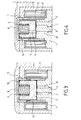
Figure 2 is a longitudinal section of an embodiment according to the present invention. -
Figure 3 is a partial view, at an enlarged scale offigure 2 . -
Figure 4 is a modification of the embodiment offigure 3 . - With reference to
Figure 1 , the known embodiment to be improved comprises a valve body 1 having an internallongitudinal bore 2 within which may move alongitudinal axis 3. The small clearance betweenbore 2 andaxis 3 is filled with fuel. - The
axis 3 comprises at one end aball 4 resting on the opening of aconduct 7 and is fixed to theplunger 5 at its other end. - A
spring 6 is pushing downward theplunger 5 in such a way thatball 4 is maintained closing the opening ofconduct 7.Conduct 7 is arranged through an end plug of a common rail to allow discharging the common rail to a fuel tank (not shown). -
Spring 6 is held by bearingcap 8 which is partially surroundingplunger 5 with a gap or clearance filled with fuel. - This clearance is large enough to allow free movement of the plunger.
- The electro-
magnetic coil 9 is energized to increase the force applied onto the ball downwards. Whencoil 9 reduces the force applied onto the ball, the fluid pressure is released through the seat towards the fuel tank. Such plunger motion needs to be controlled to avoid oscillation generating loss of control of the pressure drop. - However it appeared, during use, that displacement of the
movable plunger 5 may be jammed. - Moreover, since
axis 3 is guided axially in thehead part 8 of the valve in its top end and in the lower part of the valve in the lower end ofbore 2, and since the middle portion ofaxis 3 is fixed to plunger 5, the valve arrangement ofFig. 1 requires an excellent concentricity between the valve body 1 and thevalve head part 8, which increases manufacturing cost. -
Figure 2 is showing the improved embodiment. In thisfigure 2 same elements as infigure 1 are bearing the same references. - In this
embodiment plunger 5 is not anymore fixed tolongitudinal axis 3 but is simply resting on it by action ofspring 6, thus suppressing one cause of jamming of theplunger 5. - Another modification is that the external surface of
plunger 5 is covered by asleeve 11 of non-magnetic material having good friction characteristics, such as nylon or PTFE, whose thickness is tunable in order to determine exactly the thickness of the film of fuel between themovable plunger 5 and the internal wall ofcap 8. - Another
sleeve 12 made of non magnetic material is placed in extension to the lateral walls ofcap 8. - Guiding of
longitudinal axis 3 withinbore 2 is obtained by the length ofaxis 3. To achieve the guiding ofaxis 3, the cross section ofaxis 3 may be well adjusted to a corresponding cross section ofbore 2, e.g.; both circular in shape. In that case, the space available for fluid communication through thebore 2 may be insufficient for proper operations of the valve. As shown onfigure 4 , anadditional drilling 15 of equilibration may be provided through valve body 1 to ensure fluid communication between the valve seat and thecavity containing plunger 5 inbearing cap 8. - In an alternative embodiment, the cross section of
axis 3 does not coincide with the cross section ofbore 2, so that some space remains aroundaxis 3 for fluid communication throughbore 2. For example, thebore 2 may have a circular cross-section whereasaxis 3 has a hexagonal or trilobic cross-section. Whenplunger 5 is moved up againstspring 6, there is a flow of the fuel in the film of fuel existing between the external wall ofplunger 5 and the internal wall ofcap 8 towardsbore 2. - The said flow is controlled by the thickness of the film of fuel the thickness of which is determined by the importance of the space between the external wall of
plunger 5 and the internal wall ofcap 8 and therefore by the thickness ofsleeve 11, which can be precisely controlled and selected. - In an embodiment, the cross-section of
plunger 5 has the same shape as the internal space of bearingcap 8, e.g. both circular, so that a film of fuel with substantially uniform thickness exists all around theplunger 5. - In a preferred embodiment, the cross-section of
plunger 5 has a different shape from the internal space of bearingcap 8, e.g. an hexagonal plunger in a circular space or other, so that at some portions of the circumference of theplunger 5 thesleeve 11 is in sliding contact with the internal wall of bearingcap 8 to provide axial guiding of theplunger 5, while at other portions of the circumference of theplunger 5, thesleeve 11 is spaced from the internal wall of bearingcap 8 to create restricted passages for fluid communication between theroom 10 and thebore 2. - Flow control could be also realized by drilling an
additional conduct 14 of precisely determineddiameter connecting bore 2 and the housing ofspring 6 which communicates withroom 10 situated aboveplunger 5. - In another embodiment, the
spring 6 is replaced by a similar spring arranged on the opposite side of theplunger 5, e.g. within arecess 20 of valve body 1 around the end portion ofaxis 3. In that case, as long as thecoil 9 is not energized, the spring urges theplunger 5 towards the bearingcap 8 at some distance from the end ofaxis 3, thus leaving theaxis 3 andball 4 to float between an open and a closed state depending on pressure conditions existing in the common rail. In that case, at rest, the flow rate through the valve is only controlled by the diameter of theconduct 7. - Due to the fact that the upper end portion of
axis 3 is not attached toplunger 5, the length ofaxis 3 can be reduced and a concentricity requirement between valve body 1 and valve head part 21 can be relaxed compared to the embodiment ofFig. 1 . - In an embodiment,
sleeve 11 is arranged against the internal surface of the lateral wall of bearingcap 8 instead of the external surface ofplunger 5. The function of thesleeve 11 remains the same in that case. - The
sleeve 11 can be made independently from the other parts of the valve, e.g. under the form of a foil of PTFE and inserted in the valve during assembly. Alternatively, thesleeve 11 can be made as a preexisting coating on the surface ofplunger 5 or bearingcap 11, e.g. obtained by spraying the sleeve material on the surface before assembly. - The invention is not limited to the described embodiments. The appended claims are to be construed as embodying all modification and alternative constructions that may be occurred to one skilled in the art, which fairly fall within the basic teaching here, set forth.
- The use of the verb "to comprise" or "to include" and its conjugations does not exclude the presence of elements or steps other than those stated in a claim. Furthermore, the use of the article "a" or "an" preceding an element or step does not exclude the presence of a plurality of such elements or steps.
- In the claims, any reference signs placed between parentheses shall not be construed as limiting the scope of the claims.
Claims (14)
- An electro-valve for discharging a common rail while maintaining a minimum pressure, comprising an electro-magnetic coil (9) inside which is arranged a bearing cap (8) and a movable plunger (5), said movable plunger controlling the displacements of a movable axis (3) engaging a ball or needle (4), said movable plunger (5) being urged by a spring (6) housed inside the bearing cap (8), wherein a bottom wall of the bearing cap surrounds an external surface of the movable plunger (5), wherein a clearance between the external surface of the plunger (5) and an internal wall of the bearing cap (8) is filled with a film of fuel, the opening movement of the plunger causing the fuel to flow from a room (10) situated on top of the plunger (5) to a bore (2) in which the axis (3) is arranged, wherein a sleeve (11) of a controlled thickness is arranged around the plunger (5) within the clearance to set the thickness of said film of fuel, the pressure being controlled by the association of the ball or needle (4)with a seat of the valve.
- An electro-valve according to claim 1, wherein the sleeve is arranged against the external surface of the plunger (5), wherein a passage between the external surface of the sleeve (11) and the internal wall of the bearing cap (8) constitutes a restricted passage for a flow of fuel between the room (10) and the bore (2).
- An electro-valve according to claim 1, wherein the sleeve is arranged against the internal surface of the bearing cap (8), wherein a passage between the internal surface of the sleeve (11) and the external wall of the plunger (5) constitutes a restricted passage for a flow of fuel between the room (10) and the bore (2).
- An electro-valve according to any one of claims 1 to 3, wherein a conduct (14) drilled through the plunger (5) constitutes a second restricted passage regulating the flow of fuel.
- An electro-valve according to any one of claims 1 to 4, wherein the plunger (5) has a different cross-sectional shape from the internal wall of bearing cap (8), so that first portions of the circumference of the sleeve (11) are in sliding contact with the internal wall of the bearing cap (8) or external surface of the plunger (5) to guide the plunger in the bearing cap, and second portions of the circumference of the sleeve (11) are spaced from the internal wall of the bearing cap (8) or external surface of the plunger (5) to create restricted passages for fluid communication between the room (10) and the bore (2)..
- An electro-valve according to claim 5, wherein the internal wall of the bearing cap (8) has a circular cross-section and the external surface of the plunger (5) has a non-circular cross-section.
- An electro-valve according to any one of claims 1 to 6, wherein an additional drilling (15) is provided through a valve body (1) from a seat cavity of the valve to a plunger cavity.
- An electro-valve according to any one of claims 1 to 7, wherein the spring (6) causes the plunger (5) to rest against an end of the axis (3) to urge the axis in a closing position of the valve.
- An electro-valve according to any one of claims 1 to 7, wherein the spring (6) causes the plunger (5) to rest against an end wall of the bearing cap (8) opposite to the axis (3).
- An electro-valve according to claim 9, wherein the spring is arranged in a recess (20) of a valve body (1) around the axis (3).
- An electro-valve according to any one of claims 1 to 10, in which the sleeve (11) is made of non magnetic material having good sliding characteristics.
- An electro-valve according to any one of claims 1 to 11, in which the sleeve (11) has a tunable thickness.
- An electro-valve according to any one of claims 1 to 12, in which the sleeve (11) comprises a coating on the surface of the plunger (5) or on the surface of the bearing cap (8).
- An electro-valve according to any one of claims 1 to 12, in which the sleeve (11) comprises a coating on the surface of a tube (12) placed in extension to a lateral wall of the bearing cap (8).
Priority Applications (6)
| Application Number | Priority Date | Filing Date | Title |
|---|---|---|---|
| EP11169945A EP2535554A1 (en) | 2011-06-15 | 2011-06-15 | Electro-valve for discharging common rail |
| JP2014515172A JP5898309B2 (en) | 2011-06-15 | 2012-06-13 | Solenoid valve for common rail discharge |
| PCT/EP2012/061182 WO2012171948A1 (en) | 2011-06-15 | 2012-06-13 | Electro-valve for discharging common rail |
| KR1020147000357A KR101612118B1 (en) | 2011-06-15 | 2012-06-13 | Electro-valve for discharging common rail |
| CN201280029425.4A CN103703240B (en) | 2011-06-15 | 2012-06-13 | For discharging the electric valve of common rail |
| US14/126,009 US9297472B2 (en) | 2011-06-15 | 2012-06-13 | Electro-valve for discharging common rail |
Applications Claiming Priority (1)
| Application Number | Priority Date | Filing Date | Title |
|---|---|---|---|
| EP11169945A EP2535554A1 (en) | 2011-06-15 | 2011-06-15 | Electro-valve for discharging common rail |
Publications (1)
| Publication Number | Publication Date |
|---|---|
| EP2535554A1 true EP2535554A1 (en) | 2012-12-19 |
Family
ID=46354225
Family Applications (1)
| Application Number | Title | Priority Date | Filing Date |
|---|---|---|---|
| EP11169945A Withdrawn EP2535554A1 (en) | 2011-06-15 | 2011-06-15 | Electro-valve for discharging common rail |
Country Status (6)
| Country | Link |
|---|---|
| US (1) | US9297472B2 (en) |
| EP (1) | EP2535554A1 (en) |
| JP (1) | JP5898309B2 (en) |
| KR (1) | KR101612118B1 (en) |
| CN (1) | CN103703240B (en) |
| WO (1) | WO2012171948A1 (en) |
Cited By (1)
| Publication number | Priority date | Publication date | Assignee | Title |
|---|---|---|---|---|
| GB2582579A (en) * | 2019-03-26 | 2020-09-30 | Delphi Tech Ip Ltd | High pressure valve of a common rail |
Families Citing this family (6)
| Publication number | Priority date | Publication date | Assignee | Title |
|---|---|---|---|---|
| FR3023347B1 (en) * | 2014-07-01 | 2016-06-24 | Delphi Int Operations Luxembourg Sarl | PRESSURE CONTROL SOLENOID VALVE |
| FR3034161A1 (en) * | 2015-03-26 | 2016-09-30 | Delphi Int Operations Luxembourg Sarl | HIGH PRESSURE VALVE SEALED ACTUATOR |
| GB201509225D0 (en) * | 2015-05-29 | 2015-07-15 | Delphi Int Operations Lux Srl | High pressure valve |
| KR101926914B1 (en) | 2016-07-22 | 2018-12-07 | 현대자동차주식회사 | Fuel supplying valve for fuel cell system |
| CN106351760A (en) * | 2016-10-31 | 2017-01-25 | 江阴市天润机械制造有限公司 | High-pressure common-rail fuel metering valve |
| KR102882946B1 (en) * | 2023-10-10 | 2025-11-07 | 엠케이프리시젼 주식회사 | Mass Flow Controller |
Citations (5)
| Publication number | Priority date | Publication date | Assignee | Title |
|---|---|---|---|---|
| EP0267162A2 (en) * | 1986-11-07 | 1988-05-11 | ELASIS SISTEMA RICERCA FIAT NEL MEZZOGIORNO Società Consortile per Azioni | Pressure-regulating solenoid valve, particularly for high-pressure circuits of fuel injection systems for internal combustion engines |
| EP0990791A1 (en) * | 1998-09-29 | 2000-04-05 | Eaton | Electromagnetic pressure regulating valve |
| JP2004011448A (en) * | 2002-06-04 | 2004-01-15 | Nippon Soken Inc | Pressure reducing valve |
| EP1408388A1 (en) * | 2002-10-09 | 2004-04-14 | Robert Bosch Gmbh | Flow regulating device in particular for a fuel injection system of an internal combustion engine |
| EP1557597A1 (en) * | 2004-01-21 | 2005-07-27 | Robert Bosch Gmbh | Pressure control valve for a high pressure reservoir of an internal combustion engine |
Family Cites Families (28)
| Publication number | Priority date | Publication date | Assignee | Title |
|---|---|---|---|---|
| US2826215A (en) * | 1954-04-21 | 1958-03-11 | Alco Valve Co | Balanced pressure solenoid valve |
| US3737141A (en) * | 1972-04-13 | 1973-06-05 | Control Concepts | Normally closed solenoid operated valve |
| JPS6022063A (en) * | 1983-07-19 | 1985-02-04 | Nissan Motor Co Ltd | Fuel injection pump |
| US4731914A (en) * | 1984-01-06 | 1988-03-22 | Zeuner Kenneth W | Method for manufacturing an electrohydraulic valve assembly |
| US4638974A (en) * | 1984-01-06 | 1987-01-27 | Zeuner Kenneth W | Electrohydraulic valve assemblies and method |
| JPS6196162A (en) * | 1984-10-17 | 1986-05-14 | Nippon Denso Co Ltd | Fuel injection rate controller for diesel engine |
| DE3439378A1 (en) * | 1984-10-27 | 1986-04-30 | Heller Hydraulik GmbH, 7440 Nürtingen | Pressure control valve and a method for producing such a pressure control valve |
| JPH03121260A (en) * | 1989-10-02 | 1991-05-23 | Yamaha Motor Co Ltd | Valve guide structure for air-fuel injection type two-cycle engine |
| IT220662Z2 (en) * | 1990-10-31 | 1993-10-08 | Elasis Sistema Ricerca Fita Nel Mezzogiorno Soc.Consortile P.A. | IMPROVEMENTS TO THE PILOT VALVE AND TO THE RELATED STILL OF ORDER AN ELECTROMAGNETIC INJECTOR FOR FUEL INJECTION SYSTEMS OF INTERNAL COMBUSTION ENGINES |
| DE4344440A1 (en) * | 1993-12-24 | 1995-06-29 | Teves Gmbh Alfred | Solenoid valve, in particular for slip-controlled motor vehicle brake systems |
| IT1319838B1 (en) * | 2000-02-15 | 2003-11-03 | Elasis Sistema Ricerca Fiat | IMPROVEMENT OF A SOLENOID VALVE FOR THE ADJUSTMENT OF THE PRESSURE OF FUEL SUPPLY TO A COMBUSTION ENGINE |
| DE10036576A1 (en) * | 2000-07-27 | 2002-02-07 | Bosch Gmbh Robert | Electromagnetically operated valve, in particular for hydraulic brake systems in motor vehicles |
| JP2002286137A (en) * | 2001-03-23 | 2002-10-03 | Isuzu Motors Ltd | Manufacturing method of sliding member |
| DE10231135A1 (en) * | 2002-07-10 | 2004-01-29 | Robert Bosch Gmbh | Pressure relief valve |
| JP4206737B2 (en) * | 2002-11-29 | 2009-01-14 | 株式会社アドヴィックス | Normally closed solenoid valve |
| JP2005344685A (en) * | 2004-06-07 | 2005-12-15 | Denso Corp | High pressure pump |
| JP4058026B2 (en) * | 2004-06-16 | 2008-03-05 | 株式会社ケーヒン | Electromagnetic fuel injection valve |
| JP4572776B2 (en) * | 2005-08-24 | 2010-11-04 | 株式会社デンソー | Flow control valve |
| JP2006138397A (en) * | 2004-11-12 | 2006-06-01 | Denso Corp | solenoid valve |
| DE102004062004A1 (en) * | 2004-12-23 | 2006-07-13 | Robert Bosch Gmbh | Pressure control valve |
| JP4193822B2 (en) * | 2005-07-28 | 2008-12-10 | 株式会社デンソー | Valve device |
| JP2007132222A (en) | 2005-11-08 | 2007-05-31 | Denso Corp | Fuel injection valve |
| JP4609336B2 (en) * | 2006-02-08 | 2011-01-12 | 株式会社デンソー | solenoid valve |
| DE102007062176A1 (en) * | 2007-12-21 | 2009-06-25 | Robert Bosch Gmbh | Pressure control valve for regulating the pressure in a high pressure fuel accumulator |
| JP4591593B2 (en) * | 2008-02-13 | 2010-12-01 | 株式会社デンソー | Fuel injection valve |
| JP5478051B2 (en) * | 2008-10-30 | 2014-04-23 | 日立オートモティブシステムズ株式会社 | High pressure fuel supply pump |
| JP4866893B2 (en) * | 2008-10-30 | 2012-02-01 | 日立オートモティブシステムズ株式会社 | Electromagnetically driven valve mechanism and high-pressure fuel supply pump using the same |
| WO2013186859A1 (en) * | 2012-06-12 | 2013-12-19 | トヨタ自動車株式会社 | Normally closed solenoid valve |
-
2011
- 2011-06-15 EP EP11169945A patent/EP2535554A1/en not_active Withdrawn
-
2012
- 2012-06-13 CN CN201280029425.4A patent/CN103703240B/en active Active
- 2012-06-13 US US14/126,009 patent/US9297472B2/en active Active
- 2012-06-13 KR KR1020147000357A patent/KR101612118B1/en active Active
- 2012-06-13 WO PCT/EP2012/061182 patent/WO2012171948A1/en not_active Ceased
- 2012-06-13 JP JP2014515172A patent/JP5898309B2/en active Active
Patent Citations (5)
| Publication number | Priority date | Publication date | Assignee | Title |
|---|---|---|---|---|
| EP0267162A2 (en) * | 1986-11-07 | 1988-05-11 | ELASIS SISTEMA RICERCA FIAT NEL MEZZOGIORNO Società Consortile per Azioni | Pressure-regulating solenoid valve, particularly for high-pressure circuits of fuel injection systems for internal combustion engines |
| EP0990791A1 (en) * | 1998-09-29 | 2000-04-05 | Eaton | Electromagnetic pressure regulating valve |
| JP2004011448A (en) * | 2002-06-04 | 2004-01-15 | Nippon Soken Inc | Pressure reducing valve |
| EP1408388A1 (en) * | 2002-10-09 | 2004-04-14 | Robert Bosch Gmbh | Flow regulating device in particular for a fuel injection system of an internal combustion engine |
| EP1557597A1 (en) * | 2004-01-21 | 2005-07-27 | Robert Bosch Gmbh | Pressure control valve for a high pressure reservoir of an internal combustion engine |
Cited By (2)
| Publication number | Priority date | Publication date | Assignee | Title |
|---|---|---|---|---|
| GB2582579A (en) * | 2019-03-26 | 2020-09-30 | Delphi Tech Ip Ltd | High pressure valve of a common rail |
| GB2582579B (en) * | 2019-03-26 | 2022-02-16 | Delphi Tech Ip Ltd | High pressure valve of a common rail |
Also Published As
| Publication number | Publication date |
|---|---|
| JP2014518344A (en) | 2014-07-28 |
| KR20140019026A (en) | 2014-02-13 |
| KR101612118B1 (en) | 2016-04-12 |
| CN103703240A (en) | 2014-04-02 |
| WO2012171948A1 (en) | 2012-12-20 |
| JP5898309B2 (en) | 2016-04-06 |
| US20140175313A1 (en) | 2014-06-26 |
| CN103703240B (en) | 2016-08-17 |
| US9297472B2 (en) | 2016-03-29 |
Similar Documents
| Publication | Publication Date | Title |
|---|---|---|
| US9297472B2 (en) | Electro-valve for discharging common rail | |
| EP2687713A1 (en) | Valve assembly | |
| KR102394017B1 (en) | Fluid metering valve | |
| US10006428B2 (en) | Electromagnetic fuel injection valve | |
| US20170152822A1 (en) | Fuel Injector for an Internal Combustion Engine | |
| JP2016061196A (en) | High pressure fuel supply pump | |
| EP2971900B1 (en) | Apparatus for controlling the lift of a valve member | |
| KR20200120547A (en) | Valve for metering a fluid | |
| JP2018528354A (en) | Electric actuator of valve mechanism | |
| EP4720496A1 (en) | Fuel injector | |
| JP2017101621A (en) | Relief valve device and high-pressure pump using the same | |
| JP5756488B2 (en) | Valve device | |
| JP2018003789A (en) | Fuel injection valve and common rail injection system | |
| JP2011069292A (en) | Fuel injection valve | |
| JP2020500274A (en) | Valve for metering gas | |
| EP3156638A1 (en) | Fuel injector | |
| JP2016528431A (en) | Injection device | |
| US20240209822A1 (en) | Valve assembly for a fuel pump | |
| EP3230577B1 (en) | Fuel injector | |
| WO2022184777A1 (en) | Improved injector | |
| WO2015124340A1 (en) | Fuel injector | |
| JP2006274942A (en) | Fuel injection valve | |
| JP2011102571A (en) | Fuel injection valve | |
| JP2010236368A (en) | Fuel injection valve | |
| JP2019007390A (en) | Electromagnetic regulation valve |
Legal Events
| Date | Code | Title | Description |
|---|---|---|---|
| PUAI | Public reference made under article 153(3) epc to a published international application that has entered the european phase |
Free format text: ORIGINAL CODE: 0009012 |
|
| AK | Designated contracting states |
Kind code of ref document: A1 Designated state(s): AL AT BE BG CH CY CZ DE DK EE ES FI FR GB GR HR HU IE IS IT LI LT LU LV MC MK MT NL NO PL PT RO RS SE SI SK SM TR |
|
| AX | Request for extension of the european patent |
Extension state: BA ME |
|
| 17P | Request for examination filed |
Effective date: 20130619 |
|
| RAX | Requested extension states of the european patent have changed |
Extension state: ME Payment date: 20130619 Extension state: BA Payment date: 20130619 |
|
| RBV | Designated contracting states (corrected) |
Designated state(s): AL AT BE BG CH CY CZ DE DK EE ES FI FR GB GR HR HU IE IS IT LI LT LU LV MC MK MT NL NO PL PT RO RS SE SI SK SM TR |
|
| 17Q | First examination report despatched |
Effective date: 20140106 |
|
| RAP1 | Party data changed (applicant data changed or rights of an application transferred) |
Owner name: DELPHI INTERNATIONAL OPERATIONS LUXEMBOURG S.A.R.L |
|
| STAA | Information on the status of an ep patent application or granted ep patent |
Free format text: STATUS: THE APPLICATION IS DEEMED TO BE WITHDRAWN |
|
| 18D | Application deemed to be withdrawn |
Effective date: 20180404 |