EP2535537B1 - Exhaust gas purification device - Google Patents
Exhaust gas purification device Download PDFInfo
- Publication number
- EP2535537B1 EP2535537B1 EP11742270.9A EP11742270A EP2535537B1 EP 2535537 B1 EP2535537 B1 EP 2535537B1 EP 11742270 A EP11742270 A EP 11742270A EP 2535537 B1 EP2535537 B1 EP 2535537B1
- Authority
- EP
- European Patent Office
- Prior art keywords
- exhaust gas
- case
- sensor
- catalyst
- filter
- Prior art date
- Legal status (The legal status is an assumption and is not a legal conclusion. Google has not performed a legal analysis and makes no representation as to the accuracy of the status listed.)
- Active
Links
Images


Classifications
-
- F—MECHANICAL ENGINEERING; LIGHTING; HEATING; WEAPONS; BLASTING
- F01—MACHINES OR ENGINES IN GENERAL; ENGINE PLANTS IN GENERAL; STEAM ENGINES
- F01N—GAS-FLOW SILENCERS OR EXHAUST APPARATUS FOR MACHINES OR ENGINES IN GENERAL; GAS-FLOW SILENCERS OR EXHAUST APPARATUS FOR INTERNAL COMBUSTION ENGINES
- F01N13/00—Exhaust or silencing apparatus characterised by constructional features ; Exhaust or silencing apparatus, or parts thereof, having pertinent characteristics not provided for in, or of interest apart from, groups F01N1/00 - F01N5/00, F01N9/00, F01N11/00
- F01N13/008—Mounting or arrangement of exhaust sensors in or on exhaust apparatus
-
- F—MECHANICAL ENGINEERING; LIGHTING; HEATING; WEAPONS; BLASTING
- F01—MACHINES OR ENGINES IN GENERAL; ENGINE PLANTS IN GENERAL; STEAM ENGINES
- F01N—GAS-FLOW SILENCERS OR EXHAUST APPARATUS FOR MACHINES OR ENGINES IN GENERAL; GAS-FLOW SILENCERS OR EXHAUST APPARATUS FOR INTERNAL COMBUSTION ENGINES
- F01N13/00—Exhaust or silencing apparatus characterised by constructional features ; Exhaust or silencing apparatus, or parts thereof, having pertinent characteristics not provided for in, or of interest apart from, groups F01N1/00 - F01N5/00, F01N9/00, F01N11/00
- F01N13/009—Exhaust or silencing apparatus characterised by constructional features ; Exhaust or silencing apparatus, or parts thereof, having pertinent characteristics not provided for in, or of interest apart from, groups F01N1/00 - F01N5/00, F01N9/00, F01N11/00 having two or more separate purifying devices arranged in series
- F01N13/0097—Exhaust or silencing apparatus characterised by constructional features ; Exhaust or silencing apparatus, or parts thereof, having pertinent characteristics not provided for in, or of interest apart from, groups F01N1/00 - F01N5/00, F01N9/00, F01N11/00 having two or more separate purifying devices arranged in series the purifying devices are arranged in a single housing
-
- F—MECHANICAL ENGINEERING; LIGHTING; HEATING; WEAPONS; BLASTING
- F01—MACHINES OR ENGINES IN GENERAL; ENGINE PLANTS IN GENERAL; STEAM ENGINES
- F01N—GAS-FLOW SILENCERS OR EXHAUST APPARATUS FOR MACHINES OR ENGINES IN GENERAL; GAS-FLOW SILENCERS OR EXHAUST APPARATUS FOR INTERNAL COMBUSTION ENGINES
- F01N13/00—Exhaust or silencing apparatus characterised by constructional features ; Exhaust or silencing apparatus, or parts thereof, having pertinent characteristics not provided for in, or of interest apart from, groups F01N1/00 - F01N5/00, F01N9/00, F01N11/00
- F01N13/02—Exhaust or silencing apparatus characterised by constructional features ; Exhaust or silencing apparatus, or parts thereof, having pertinent characteristics not provided for in, or of interest apart from, groups F01N1/00 - F01N5/00, F01N9/00, F01N11/00 having two or more separate silencers in series
-
- F—MECHANICAL ENGINEERING; LIGHTING; HEATING; WEAPONS; BLASTING
- F01—MACHINES OR ENGINES IN GENERAL; ENGINE PLANTS IN GENERAL; STEAM ENGINES
- F01N—GAS-FLOW SILENCERS OR EXHAUST APPARATUS FOR MACHINES OR ENGINES IN GENERAL; GAS-FLOW SILENCERS OR EXHAUST APPARATUS FOR INTERNAL COMBUSTION ENGINES
- F01N13/00—Exhaust or silencing apparatus characterised by constructional features ; Exhaust or silencing apparatus, or parts thereof, having pertinent characteristics not provided for in, or of interest apart from, groups F01N1/00 - F01N5/00, F01N9/00, F01N11/00
- F01N13/08—Other arrangements or adaptations of exhaust conduits
-
- F—MECHANICAL ENGINEERING; LIGHTING; HEATING; WEAPONS; BLASTING
- F01—MACHINES OR ENGINES IN GENERAL; ENGINE PLANTS IN GENERAL; STEAM ENGINES
- F01N—GAS-FLOW SILENCERS OR EXHAUST APPARATUS FOR MACHINES OR ENGINES IN GENERAL; GAS-FLOW SILENCERS OR EXHAUST APPARATUS FOR INTERNAL COMBUSTION ENGINES
- F01N13/00—Exhaust or silencing apparatus characterised by constructional features ; Exhaust or silencing apparatus, or parts thereof, having pertinent characteristics not provided for in, or of interest apart from, groups F01N1/00 - F01N5/00, F01N9/00, F01N11/00
- F01N13/14—Exhaust or silencing apparatus characterised by constructional features ; Exhaust or silencing apparatus, or parts thereof, having pertinent characteristics not provided for in, or of interest apart from, groups F01N1/00 - F01N5/00, F01N9/00, F01N11/00 having thermal insulation
- F01N13/141—Double-walled exhaust pipes or housings
- F01N13/143—Double-walled exhaust pipes or housings with air filling the space between both walls
-
- F—MECHANICAL ENGINEERING; LIGHTING; HEATING; WEAPONS; BLASTING
- F01—MACHINES OR ENGINES IN GENERAL; ENGINE PLANTS IN GENERAL; STEAM ENGINES
- F01N—GAS-FLOW SILENCERS OR EXHAUST APPARATUS FOR MACHINES OR ENGINES IN GENERAL; GAS-FLOW SILENCERS OR EXHAUST APPARATUS FOR INTERNAL COMBUSTION ENGINES
- F01N13/00—Exhaust or silencing apparatus characterised by constructional features ; Exhaust or silencing apparatus, or parts thereof, having pertinent characteristics not provided for in, or of interest apart from, groups F01N1/00 - F01N5/00, F01N9/00, F01N11/00
- F01N13/18—Construction facilitating manufacture, assembly, or disassembly
- F01N13/1805—Fixing exhaust manifolds, exhaust pipes or pipe sections to each other, to engine or to vehicle body
-
- F—MECHANICAL ENGINEERING; LIGHTING; HEATING; WEAPONS; BLASTING
- F01—MACHINES OR ENGINES IN GENERAL; ENGINE PLANTS IN GENERAL; STEAM ENGINES
- F01N—GAS-FLOW SILENCERS OR EXHAUST APPARATUS FOR MACHINES OR ENGINES IN GENERAL; GAS-FLOW SILENCERS OR EXHAUST APPARATUS FOR INTERNAL COMBUSTION ENGINES
- F01N13/00—Exhaust or silencing apparatus characterised by constructional features ; Exhaust or silencing apparatus, or parts thereof, having pertinent characteristics not provided for in, or of interest apart from, groups F01N1/00 - F01N5/00, F01N9/00, F01N11/00
- F01N13/18—Construction facilitating manufacture, assembly, or disassembly
- F01N13/1838—Construction facilitating manufacture, assembly, or disassembly characterised by the type of connection between parts of exhaust or silencing apparatus, e.g. between housing and tubes, between tubes and baffles
- F01N13/1844—Mechanical joints
- F01N13/1855—Mechanical joints the connection being realised by using bolts, screws, rivets or the like
-
- F—MECHANICAL ENGINEERING; LIGHTING; HEATING; WEAPONS; BLASTING
- F01—MACHINES OR ENGINES IN GENERAL; ENGINE PLANTS IN GENERAL; STEAM ENGINES
- F01N—GAS-FLOW SILENCERS OR EXHAUST APPARATUS FOR MACHINES OR ENGINES IN GENERAL; GAS-FLOW SILENCERS OR EXHAUST APPARATUS FOR INTERNAL COMBUSTION ENGINES
- F01N3/00—Exhaust or silencing apparatus having means for purifying, rendering innocuous, or otherwise treating exhaust
- F01N3/02—Exhaust or silencing apparatus having means for purifying, rendering innocuous, or otherwise treating exhaust for cooling, or for removing solid constituents of, exhaust
- F01N3/021—Exhaust or silencing apparatus having means for purifying, rendering innocuous, or otherwise treating exhaust for cooling, or for removing solid constituents of, exhaust by means of filters
-
- F—MECHANICAL ENGINEERING; LIGHTING; HEATING; WEAPONS; BLASTING
- F01—MACHINES OR ENGINES IN GENERAL; ENGINE PLANTS IN GENERAL; STEAM ENGINES
- F01N—GAS-FLOW SILENCERS OR EXHAUST APPARATUS FOR MACHINES OR ENGINES IN GENERAL; GAS-FLOW SILENCERS OR EXHAUST APPARATUS FOR INTERNAL COMBUSTION ENGINES
- F01N3/00—Exhaust or silencing apparatus having means for purifying, rendering innocuous, or otherwise treating exhaust
- F01N3/08—Exhaust or silencing apparatus having means for purifying, rendering innocuous, or otherwise treating exhaust for rendering innocuous
- F01N3/10—Exhaust or silencing apparatus having means for purifying, rendering innocuous, or otherwise treating exhaust for rendering innocuous by thermal or catalytic conversion of noxious components of exhaust
- F01N3/18—Exhaust or silencing apparatus having means for purifying, rendering innocuous, or otherwise treating exhaust for rendering innocuous by thermal or catalytic conversion of noxious components of exhaust characterised by methods of operation; Control
- F01N3/20—Exhaust or silencing apparatus having means for purifying, rendering innocuous, or otherwise treating exhaust for rendering innocuous by thermal or catalytic conversion of noxious components of exhaust characterised by methods of operation; Control specially adapted for catalytic conversion ; Methods of operation or control of catalytic converters
-
- F—MECHANICAL ENGINEERING; LIGHTING; HEATING; WEAPONS; BLASTING
- F01—MACHINES OR ENGINES IN GENERAL; ENGINE PLANTS IN GENERAL; STEAM ENGINES
- F01N—GAS-FLOW SILENCERS OR EXHAUST APPARATUS FOR MACHINES OR ENGINES IN GENERAL; GAS-FLOW SILENCERS OR EXHAUST APPARATUS FOR INTERNAL COMBUSTION ENGINES
- F01N3/00—Exhaust or silencing apparatus having means for purifying, rendering innocuous, or otherwise treating exhaust
- F01N3/08—Exhaust or silencing apparatus having means for purifying, rendering innocuous, or otherwise treating exhaust for rendering innocuous
- F01N3/10—Exhaust or silencing apparatus having means for purifying, rendering innocuous, or otherwise treating exhaust for rendering innocuous by thermal or catalytic conversion of noxious components of exhaust
- F01N3/24—Exhaust or silencing apparatus having means for purifying, rendering innocuous, or otherwise treating exhaust for rendering innocuous by thermal or catalytic conversion of noxious components of exhaust characterised by constructional aspects of converting apparatus
- F01N3/28—Construction of catalytic reactors
-
- F—MECHANICAL ENGINEERING; LIGHTING; HEATING; WEAPONS; BLASTING
- F01—MACHINES OR ENGINES IN GENERAL; ENGINE PLANTS IN GENERAL; STEAM ENGINES
- F01N—GAS-FLOW SILENCERS OR EXHAUST APPARATUS FOR MACHINES OR ENGINES IN GENERAL; GAS-FLOW SILENCERS OR EXHAUST APPARATUS FOR INTERNAL COMBUSTION ENGINES
- F01N2260/00—Exhaust treating devices having provisions not otherwise provided for
- F01N2260/20—Exhaust treating devices having provisions not otherwise provided for for heat or sound protection, e.g. using a shield or specially shaped outer surface of exhaust device
-
- F—MECHANICAL ENGINEERING; LIGHTING; HEATING; WEAPONS; BLASTING
- F01—MACHINES OR ENGINES IN GENERAL; ENGINE PLANTS IN GENERAL; STEAM ENGINES
- F01N—GAS-FLOW SILENCERS OR EXHAUST APPARATUS FOR MACHINES OR ENGINES IN GENERAL; GAS-FLOW SILENCERS OR EXHAUST APPARATUS FOR INTERNAL COMBUSTION ENGINES
- F01N2470/00—Structure or shape of gas passages, pipes or tubes
- F01N2470/18—Structure or shape of gas passages, pipes or tubes the axis of inlet or outlet tubes being other than the longitudinal axis of apparatus
-
- Y—GENERAL TAGGING OF NEW TECHNOLOGICAL DEVELOPMENTS; GENERAL TAGGING OF CROSS-SECTIONAL TECHNOLOGIES SPANNING OVER SEVERAL SECTIONS OF THE IPC; TECHNICAL SUBJECTS COVERED BY FORMER USPC CROSS-REFERENCE ART COLLECTIONS [XRACs] AND DIGESTS
- Y10—TECHNICAL SUBJECTS COVERED BY FORMER USPC
- Y10T—TECHNICAL SUBJECTS COVERED BY FORMER US CLASSIFICATION
- Y10T137/00—Fluid handling
- Y10T137/8376—Combined
Definitions
- the present invention relates to an exhaust gas purifying device which is mounted to a diesel engine or the like, and more particularly to an exhaust gas purifying device which removes a particulate matter (a soot and a particulate) and the like which are included in an exhaust gas.
- Patent document 6 discloses an access joint for an engine exhaust system, wherein the access joint includes first and second exhaust conduits each having a conduit body and a flange unitary with the conduit body. The flanges have first surfaces that face towards one another and second surfaces that face away from one another. The joint also includes a clamp having a channel that receives the flanges and that compresses the flanges toward one another when the clamp is tightened.
- patent document 7 teaches an automotive exhaust gas system having a catalytic converter or a diesel particle filter with a substrate filter insert embedded within a double walled housing.
- the housing inner face clamps the substrate and the outer housing clamps the inner housing such that the housing and the substrate form a single entity.
- the exhaust gas temperature sensor which detects the temperature of the exhaust gas discharged form the diesel engine
- the exhaust gas pressure sensor which detects the pressure of the exhaust gas
- the exhaust gas temperature in the inner portion of the case tends to be lowered, and an outer surface of the case tends to come to a high temperature, by forming a support portion of the exhaust gas temperature sensor and a pickup portion of the exhaust gas for detecting the pressure in the single structure case between the oxidation catalyst and the soot filter.
- the present invention intends to provide an exhaust gas purifying device to which an improvement is applied by making a study of these actual conditions.
- an exhaust gas purifying device comprising: a plurality of gas purifying bodies which purifies an exhaust gas discharged by an engine; a plurality of inside cases which is inward provided with the respective gas purifying bodies; and outside cases which are inward provided with respective the inside cases, wherein an outlet end portion of the inside case in an exhaust gas upstream side and an inlet end portion of the inside case in an exhaust gas downstream side are superposed as a double structure, a sensor boss body for supporting an exhaust gas sensor is arranged in an outside surface of the outlet end portion or the inlet end portion of the double structure, and the sensor boss body is extended to an outside direction of the outside case.
- a heat shield case is provided in an outside surface of one of the inside case, the other of the inside case is inserted into the heat shield case, one end side of the heat shield case is firmly fixed to an outer peripheral surface in an inner side than an end surface of the one of the inside case, and the sensor boss body is firmly fixed to an outer peripheral surface of the heat shield case in the vicinity of the end surface of the one of the inside case.
- an inner diameter of a firmly fixing position of the sensor boss body in the heat shield case is formed larger than an outer diameter of the inside case.
- one end side of the heat shield case is fitted to the inside case, and the other end side of the heat shield case is coupled to a flange body for bonding the outside cases.
- a sensor attaching hole of the outside case is occluded by the heat shield case.
- a space is formed between an outer peripheral side of the other of the inside case in which the other end side of the heat shield case is extended, and an inner peripheral side of the heat shield case.
- the other end side of the heat shield case which is extended to the outside surface of the other of the inside case is coupled to a flange body for connecting the outside case.
- the inside case, the heat shield case and the outside case are provided as a three-layer structure, a side end of the heat shield case is formed shorter than a side end of the outside case, and a side end of the inside case is formed shorter than a side end of the heat shield case.
- the exhaust gas pressure sensor is arranged in an outside surface of the outside case, a pipe joint body for connecting the sensor piping is fastened to the sensor boss body via a pipe joint bolt, and the exhaust gas pressure sensor is connected to the sensor boss body via the sensor piping.
- a sensor support portion is integrally formed in a part of a flange body for pinching in the outside case, and a sensor bracket for attaching the exhaust gas pressure sensor is detachably provided in the sensor support portion.
- the sensor piping is extended from the sensor piping body toward the exhaust gas pressure sensor, along an outer peripheral shape of the exhaust gas purifying case.
- the exhaust gas purifying device which is provided with the plurality of gas purifying bodies which purifies the exhaust gas discharged by the engine, the plurality of inside cases which is inward provided with the respective gas purifying bodies, and the outside case which are inward provided with the respective inside cases, the outlet end portion of the inside case in the exhaust gas upstream side and the inlet end portion of the inside case in the exhaust gas downstream side are superposed as the double structure, the sensor boss body for supporting the exhaust gas sensor is arranged in the outside surface of the outlet end portion or the inlet end portion of the double structure, and the sensor boss body is extended to the outside direction of the outside case.
- the heat shield case is provided in the outside surface of the one of the inside case, the other of the inside case is inserted into the heat shield case, the one end side of the heat shield case is firmly fixed to the outer peripheral surface in the inner side than the end surface of the one of the inside case, and the sensor boss body is firmly fixed to the outer peripheral surface of the heat shield case in the vicinity of the end surface of the one of the inside case. Accordingly, it is possible to extend the outside case and the heat shield case to the position at which the gas purifying bodies are opposed, and it is possible to easily maintain the exhaust gas temperature in the inner portion of the inside case by the outside case and the heat shield case.
- the inner diameter of the firmly fixing position of the sensor boss body in the heat shield case is formed larger than the outer diameter of the inside case. Accordingly, since a gap is formed between the heat shield case and the inside case which is inward inserted to the heat shield case, it is possible to easily extract the heat shield case and the inside case. Further, it is possible to improve a heat insulating property of the opposed position of the gas purifying bodies, by the heat shield case and the outside case. It is possible to easily maintain a treating temperature of the particulate matter which the gas purifying body collects.
- the one end side of the heat shield case is fitted to the inside case, and the other end side of the heat shield case is coupled to the flange body for bonding the outside cases. Accordingly, it is possible to support the heat shield case at a high rigidity by the inside case and the flange body. It is possible to easily prevent the exhaust gas within the inside case from leaking from the gap with the heat shield case toward the outside case. It is possible to reduce a rise of a surface temperature of the outside case.
- the sensor attaching hole of the outside case is occluded by the heat shield case. Accordingly, it is possible to easily couple the exhaust gas sensor to a measuring portion by making the sensor boss body protrude to an outside direction of the outside case. It is possible to easily extend an electric wiring, a piping and the like from the sensor boss body side. Further, it is possible to easily prevent the exhaust gas within the inside case from leaking from the sensor attaching hole. It is possible to reduce a rise of the surface temperature of the outside case.
- the space is formed between the outer peripheral side of the other of the inside case in which the other end side of the heat shield case is extended, and the inner peripheral side of the heat shield case. Accordingly, it is possible to easily make the other of the inside case come in and out with respect to the heat shield case, and it is possible to easily bond or separate the inside cases and the outside cases. It is possible to improve a maintenance workability of the gas purifying bodies or the exhaust gas sensor.
- the other end side of the heat shield case which is extended to the outside surface of the other of the inside case is coupled to the flange body for connecting the outside case. Accordingly, it is possible to easily prevent the exhaust gas from leaking from the gas purifying body toward the outside case. On the basis of the heat insulating action of the outside case and the heat shield case, it is possible to reduce the lowering of the exhaust gas temperature of the gas purifying body and the rise of the surface temperature of the outside case.
- the inside case, the heat shield case and the outside case are provided as the three-layer structure, the side end of the heat shield case is formed shorter than the side end of the outside case, and the side end of the inside case is formed shorter than the side end of the heat shield case. Accordingly, it is possible to reduce the temperature lowering of the exhaust gas, and it is possible to improve a treating efficiency of the particulate matter in the exhaust gas. It is possible to reduce the rise of the surface temperature of the outside case, and it is possible to improve a workability of a maintenance of a diesel engine which is necessary during an operation.
- the exhaust gas pressure sensor is arranged in the outside surface of the outside case, the pipe joint for connecting the sensor piping is fastened to the sensor boss body via the pipe joint bolt, and the exhaust gas pressure sensor is connected to the sensor boss body via the sensor piping. Accordingly, it is not necessary to evaluate an initial setting (adjusting) condition of the exhaust gas pressure sensor per the plural specifications of engines or machine bodies. It is possible to reduce an evaluating man power for a design, a test and the like of assembling the DPF in the engine.
- the sensor support portion is integrally formed in the part of the flange body for pinching in the outside case, and the sensor bracket for attaching the exhaust gas pressure sensor is detachably provided in the sensor support portion. Accordingly, it is possible to support the exhaust gas pressure sensor to the flange body having a high rigidity, and it is possible to reduce a vibration of the exhaust gas pressure sensor. It is possible to prevent the exhaust gas pressure sensor from falling away. It is possible to easily secure a strength of the exhaust gas purifying case which constructs the DPF, or a support strength of the exhaust gas pressure sensor.
- the sensor piping is extended from the sensor piping body toward the exhaust gas pressure sensor, along the outer peripheral shape of the exhaust gas purifying case. Accordingly, it is possible to compactly arrange the sensor piping to an outer periphery of the DPF. Further, it is possible to extend the sensor piping in an optional direction from the pipe joint body toward the exhaust gas pressure sensor. It is possible to improve an assembling workability of the exhaust gas purifying case to the engine or the like.
- the worker or the tool In comparison with the conventional structure in which the sensor piping is extended from the DPF to the engine or the machine body side, the worker or the tool is hard to come into contact with the sensor piping or the like at a time of the assembling work and the maintenance work of the engine and the DPF, and it is easily protect the sensor piping or the like. It is possible to improve a handling workability of a carriage of the DPF.
- DPF 1 a continuous regeneration type diesel particulate filter 1 (hereinafter, refer to as DPF 1) as an exhaust gas purifying device. It is structured such that the DPF 1 reduces a carbon monoxide (CO) and a hydro carbon (HC) in an exhaust gas of a diesel engine 70, in addition to a removal of a particulate matter (PM) in the exhaust gas of the diesel engine 70.
- CO carbon monoxide
- HC hydro carbon
- PM particulate matter
- the DPF 1 serving as the exhaust gas purifying device is provided for collecting the particulate matter (PM) in the exhaust gas.
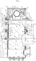
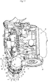
- the DPF 1 is structured as an approximately cylindrical shape which extends long in a lateral direction which intersects an output shaft (a crank shaft) of the diesel engine 70 in a plan view.
- the DPF 1 is arranged on a flywheel housing 78 of the diesel engine 70. Both left and right sides (one end side and the other end side in a moving direction of the exhaust gas) of the DPF 1 are provided with an exhaust gas inlet pipe 16 (an exhaust gas intake side), and an exhaust gas outlet pipe 34 (an exhaust gas discharge side) so as to be sorted to left and right sides of the diesel engine 70.
- the exhaust gas inlet pipe 16 in the exhaust gas intake side of the DPF 1 is detachably fastened by bolt to an exhaust manifold 71 of the diesel engine 70.
- a tail pipe 107 is connected to the exhaust gas outlet pipe 34 in the exhaust gas discharge side of the DPF 1.
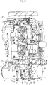
- the DPF 1 is structured such that a diesel oxidation catalyst 2, for example, a platinum or the like and a soot filter 3 of a honeycomb structure are accommodated in series side by side in a DPF casing 60 made of a heat resisting metal material, via cylindrical inside cases 4 and 20.
- the DPF 1 is attached to a flywheel housing 78 via a flange side bracket leg 61 and a casing side bracket leg 62 serving as a support body.
- one end side of the flange side bracket leg 61 is detachably fastened by bolt to an outer peripheral side of the DPF casing 60 via a flange 26 mentioned later.
- One end side of the casing side bracket leg 62 is integrally fixed by welding to an outer peripheral surface of the DPF casing 60.
- the other end side of the flange side bracket leg 61 is detachably fastened to an upper surface (a DPF attaching portion) of the flywheel housing 78 by two after attaching bolts 88.
- the other end side of the casing side bracket leg 62 is detachably fastened to the upper surface (the DPF attaching portion) of the flywheel housing 78 by a before attaching bolt 87 and the after attaching bolt 88.
- a notch hole 89 for engaging and inserting the before attaching bolt 87 is formed in the other end side of the casing side bracket leg 62.
- the before attaching bolt 87 is incompletely screwed to the upper surface of the flywheel housing 78. Further, a worker lifts up the DPF 1 by both hands, locks the casing side bracket leg 62 to the before attaching bolt 87 via the notch hole 89, and temporarily fastens the DPF 1 to the diesel engine 70. The worker can unlink both the hands from the DPF 1 in this state. Thereafter, an inlet flange body 17 is fastened to the exhaust manifold 71, and the exhaust gas inlet pipe 16 is firmly fixed to the exhaust manifold 71.
- the flange side bracket leg 61 and the casing side bracket leg 62 are fastened to the upper surface of the flywheel housing 78 by three after attaching bolts 88. Further, the before attaching bolt 87 is completely fastened, and the DPF 1 is detachably firmly fixed to the upper surface of the flywheel housing 78. In this case, the DPF 1 can be detached in accordance with an inverse procedure to the above. As a result, the DPF 1 can be stably coupled and supported to a rear portion of the diesel engine 70, in an upper portion of the flywheel housing 78 which is a high rigidity member, by the bracket legs 61 and 62 and the exhaust manifold 71. Further, it is possible to execute an attaching and detaching work of the DPF 1 to and from the diesel engine 70 by only one worker.
- the exhaust gas of the diesel engine 70 flows into the diesel oxidation catalyst 2 side within the DPF casing 60 from the exhaust manifold 71 of the diesel engine 70, and moves from the diesel oxidation catalyst 2 to the soot filter 3 side so as to be purified.
- the particulate matter in the exhaust gas can not pass through a porous shaped partition wall between cells in the soot filter 3. In other words, the particulate matter in the exhaust gas is collected in the soot filter 3. Thereafter, the exhaust gas passing through the diesel oxidation catalyst 2 and the soot filter 3 is discharged to the tail pipe 107.
- the diesel oxidation catalyst 2 is provided within an approximately cylindrical catalyst inside case 4 made of a heat resisting metal material.
- the catalyst inside case 4 is provided within an approximately cylindrical catalyst outside case 5 made of a heat resisting metal material.
- the catalyst inside case 4 is fitted to an outer side of the diesel oxidation catalyst 2 via a mat shaped catalyst heat insulating material 6 made of a ceramic fiber.
- the catalyst heat insulating material 6 is pressure inserted between the diesel oxidation catalyst 2 and the catalyst inside case 4, thereby protecting the diesel oxidation catalyst 2.
- the catalyst outside case 5 is fitted to an outer side of the catalyst inside case 4 via a support body 7 constructed by an end face L-shaped thin plate.
- the catalyst outside case 5 is one of elements which construct the DPF casing 60 mentioned above.
- the diesel oxidation catalyst 2 is protected by the catalyst heat insulating material 6.
- a stress (a mechanical vibration and a deforming force) of the catalyst outside case 5 which is transmitted to the catalyst inside case 4 is lowered by the support body 7 constructed by the thin plate.
- a discoid side lid body 8 is firmly fixed to one side end portion of the catalyst inside case 4 and the catalyst outside case 5 by welding.
- An outer lid body 9 is fastened to an outer surface side of the side lid body 8 by a bolt and a nut.
- a gas inflow side end surface 2a of the diesel oxidation catalyst 2 and the side lid body 8 are spaced only at a fixed distance L1 (a gas inflow space 11).
- the exhaust gas inflow space 11 is formed between the gas inflow side end surface 2a of the diesel oxidation catalyst 2 and the left lid body 8.
- An exhaust gas inflow port 12 which faces to the exhaust gas inflow space 11 is opened to the catalyst inside case 4 and the catalyst outside case 5.
- An occlusion ring body 15 is firmly fixed in a pinching manner between an opening edge of the catalyst inside case 4 and an opening edge of the catalyst outside case 5. Since a gap between the opening edge of the catalyst inside case 4 and the opening edge of the catalyst outside case 5 is closed by the occlusion ring body 15, it is possible to prevent the exhaust gas from flowing into between the catalyst inside case 4 and the catalyst outside case 5.
- an exhaust gas inlet pipe 16 is arranged in an outer surface of the catalyst outside case 5 in which the exhaust gas inflow port 12 is formed.
- the inlet flange body 17 is fixed by welding to one opening end portion of the exhaust gas inlet pipe 16.
- the inlet flange body 17 is detachably fastened by bolt to the exhaust manifold 71 of the diesel engine 70.
- the one opening end portion of the exhaust gas inlet pipe 16 is communicated with the exhaust manifold 71.
- the other opening end portion of the exhaust gas inlet pipe 16 is welded to the outer surface of the catalyst outside case 5 in such a manner as to cover the exhaust gas inflow port 12 from an outer side.
- a pair of reinforcing bracket bodies 18 is fixed by welding between the outer surface of the catalyst outside case 5 and the side edge of the inlet flange body 17, and a coupling strength between the exhaust manifold 71 and the exhaust gas inlet pipe 16 is secured.
- the exhaust gas of the diesel engine 70 enters into the exhaust gas inlet pipe 16 from the exhaust manifold 71, enters into the exhaust gas inflow space 11 from the exhaust gas inlet pipe 16 via the exhaust gas inflow port 12, and is supplied to the diesel oxidation catalyst 2 from the gas inflow side end surface 2a in a left side thereof.
- the nitrogen dioxide (NO2) is generated on the basis of the oxidizing action of the diesel oxidation catalyst 2.
- the soot filter 3 is provided within a filter inside case 20 which is made of a heat resisting metal material and is formed as an approximately cylindrical shape.
- the filter inside case 20 is provided within a filter outside case 21 which is made of a heat resisting metal material and is formed as an approximately cylindrical shape.
- the filter inside case 20 is fitted to an outer side of the soot filter 3 via a filter heat insulating material 22 which is made of a ceramic fiber and is formed as a mat shape.
- the filter outside case 21 is one of the elements which construct the DPF casing 60 mentioned above together with the catalyst outside case 5.
- the filter heat insulating material 22 is pressure inserted between the soot filter 3 and the filter inside case 20 so as to protect the soot filter 3.
- the catalyst inside case 4 which is formed as a cylindrical shape having a straight ridge line is constructed by an upstream side tube portion 4a which accommodates the diesel oxidation catalyst 2, and a downstream side tube portion 4b to which the filter inside case 20 mentioned below is inserted.
- the upstream side tube portion 4a and the downstream side tube portion 4b are cylinders having approximately the same diameter.
- a catalyst side junction flange 25 which is fixed by welding to an outer periphery of the catalyst inside case 4 and is formed as a thin plate ring shape
- a filter side junction flange 26 which is fixed by welding to an outer periphery of the filter inside case 20 and is formed as a thin plate ring shaped.
- the catalyst side junction flange 25 and the filter side junction flange 26 are formed as a donut shape in which a cross sectional end face is formed as an L-shaped form.
- An inner peripheral side of the L-shaped cross sectional end face of the catalyst side junction flange 25 is fixed by welding to an end portion of the downstream side tube portion 4b of the catalyst inside case 4.
- An outer peripheral side of the L-shaped cross sectional end face of the catalyst side junction flange 25 is protruded toward an outer peripheral side (a radial direction) of the catalyst outside case 5.
- a step portion 25a is formed in a folded corner portion of the L-shaped cross sectional end face of the catalyst side junction flange 25.
- An end portion in a downstream side of the catalyst outside case 5 is fixed by welding to the step portion 25a.
- an inner peripheral side of the L-shaped cross sectional end face of the filter side junction flange 26 is fixed by welding to a midway portion in an exhaust gas moving direction, in the outer periphery of the filter inside case 20.
- An outer peripheral side of the L-shaped cross sectional end face of the filter side junction flange 26 is protruded toward an outer peripheral side (a radial direction) of the filter outside case 21.
- a step portion 26a is formed in a folded corner portion of the L-shaped cross sectional end face of the filter side junction flange 26.
- An end portion in an upstream side of the filter outside case 21 is fixed by welding to the step portion 26a.
- the filter inside case 20 is formed as a cylindrical shape having a straight ridge line.
- the exhaust gas upstream side end portion and the downstream side end portion of the filter inside case 20 are cylinders having approximately the same diameter.
- an outer diameter of the diesel oxidation catalyst 2 is formed equal to an outer diameter of the soot filter 3.
- a thickness of the catalyst heat insulating material 6 is formed larger than a thickness of the filter heat insulating material 22.
- the catalyst inside case 4 and the filter inside case 20 are formed by a material having the same thickness.
- An outer diameter of the filter inside case 20 is formed smaller in comparison with an inner diameter of the downstream side tube portion 4b of the catalyst inside case 4.
- a downstream side gap 23 is formed between an inner peripheral surface of the catalyst inside case 4 and an outer peripheral surface of the filter inside case 20.
- the downstream side gap 23 is formed at a dimension (for example, 2 millimeter) which is larger than the thickness (for example, 1.5 millimeter) of each of the cases 4 and 20.
- the catalyst side junction flange 25 and the filter side junction flange 26 are confronted via the gasket 24.
- the junction flanges 25 and 26 is pinched from both sides in the exhaust gas moving direction, by a pair of thick center pinching flanges 51 and 52 which surround the outer peripheral sides of the outside cases 5 and 21.
- the catalyst outside case 5 and the filter outside case 21 are detachably coupled by fastening the center pinching flanges 51 and 52 and pinching the junction flanges 25 and 26, by means of a bolt 27 and a nut 28.
- a catalyst downstream side space 29 is formed between the diesel oxidation catalyst 2 and the soot filter 3.
- the downstream side end portion of the diesel oxidation catalyst 2 and the upstream side end portion of the soot filter 3 are faced so as to be spaced at a sensor attaching distance L2.
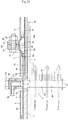
- a cylinder length L4 in the exhaust gas moving direction of the catalyst outside case 5 is formed longer than a cylinder length L3 in the exhaust gas moving direction of the upstream side tube portion 4a in the catalyst inside case 4.
- a cylinder length L6 in the exhaust gas moving direction of the filter outside case 21 is formed shorter than a cylinder length L5 in the exhaust gas moving direction of the filter inside case 20.
- a length (L2 + L3 + L5) obtained by adding the sensor attaching distance L2 of the catalyst downstream side space 29, the cylinder length L3 of the upstream side tube portion 4a of the catalyst inside case 4, and the cylinder length L5 of the filter inside case 20 is structured such as to be approximately equal to a length (L4 + L6) obtained by adding the cylinder length L4 of the catalyst outside case 5 and the cylinder length L6 of the filter outside case 21.
- the end portion in the upstream side of the filter inside case 20 protrudes from the end portion in the upstream side of the filter outside case 21 at a difference (L7 ⁇ L5 - L6) between the lengths of the cases 20 and 21. Accordingly, in a state in which the filter outside case 21 is coupled to the catalyst outside case 5, the end portion in the upstream side of the filter inside case 20 is inserted to the downstream side of the catalyst outside case 5 (the downstream side tube portion 4b of the catalyst inside case 4), at the upstream side dimension L7 of the filter inside case 20 protruding out of the filter outside case 21. In other words, the upstream side of the filter inside case 20 is inserted into the downstream side tube portion 4b (the catalyst downstream side space 29) so as to be freely extracted.
- the nitrogen dioxide (NO 2 ) which is created by the oxidizing action of the diesel oxidation catalyst 2 is supplied into the soot filter 3 from one side end face (an intake side end face) 3a.
- the particulate matter (PM) which is included in the exhaust gas of the diesel engine 70 is collected by the soot filter 3 and is continuously oxidized and removed by the nitrogen dioxide (NO 2 ).
- contents of the carbon oxide (CO) and the hydro carbon (HC) in the exhaust gas of the diesel engine 70 are reduced.
- a muffler 30 which attenuates an exhaust gas sound discharged by the diesel engine 70 has a sound absorbing inside case 31 which is made of a heat resisting metal material and is formed as an appropriately cylindrical shape, a sound absorbing outside case 32 which is made of a heat resisting metal material and is formed as an approximately cylindrical shape, and a discoid side lid body 33 which is firmly fixed by welding to a side end portion in a downstream side of the sound absorbing outside case 32.
- the sound absorbing inside case 31 is provided within the sound absorbing outside case 32.
- the sound absorbing outside case 32 constructs the DPF casing 60 mentioned above together with the catalyst outside case 5 and the filter outside case 21.
- a diameter of the cylindrical sound absorbing outside case 32 is approximately the same dimension as the diameter of the cylindrical catalyst outside case 5 or the diameter of the cylindrical filter outside case 21.
- Discoid inner lid bodies 36 and 37 are firmly fixed by welding to both side end portions in an exhaust gas moving direction of the sound absorbing inside case 31.
- a pair of exhaust gas introduction pipes 38 are provided between the inner lid bodies 36 and 37.
- An upstream side end portion of each of the exhaust gas introduction pipes 38 passes through the upstream inner lid body 36.
- a downstream side end portion of each of the exhaust gas introduction pipes 38 is occluded by the downstream inner lid body 37.
- a plurality of communication holes 39 is formed in an intermediate portion of each of the exhaust gas introduction pipes 38.
- An expansion chamber 45 is communicated within each of the exhaust gas introduction pipes 38 via a communication hole 39.
- the expansion chamber 45 is formed in an inner portion of the sound absorbing inside case 31 (between the inner lid bodies 36 and 37).
- the exhaust gas outlet pipe 34 arranged between the exhaust gas introduction pipes 38 is passed through the sound absorbing inside case 31 and the sound absorbing outside case 32.
- One end side of the exhaust gas outlet pipe 34 is occluded by the outlet lid body 35.
- a lot of exhaust holes 46 are provided in a whole of the exhaust gas outlet pipe 34 in an inner portion of the sound absorbing inside case 31.
- Each of the exhaust gas introduction pipes 38 is communicated with the exhaust gas outlet pipe 34 via a plurality of communication holes 39, the expansion chamber 45 and a lot of exhaust holes 46.
- a tail pipe 48 is connected to the other end side of the exhaust gas outlet pipe 34.
- the exhaust gas entering into both the exhaust gas introduction pipes 38 of the sound absorbing inside case 31 passes through the exhaust gas outlet pipe 34 via a plurality of communication holes 39, the expansion chamber 45 and a lot of exhaust holes 46, and is discharged out of the muffler 30 via the tail pipe 48.
- an inner diameter side of a filter outlet side junction flange 40 formed as a thin plate ring shape is fixed by welding to an end portion in a downstream side of the filter inside case 20.
- An outer diameter side of the filter outlet side junction flange 40 is protruded toward an outer peripheral side (a radially outside or a radial direction) of the filter outside case 21.
- An end portion in a downstream side of the filter outside case 21 is fixed by welding to an outer peripheral side (an end face L-shaped corner portion) of the filter outlet side junction flange 40.
- a sound absorbing side junction flange 41 which protrudes to an outer peripheral side (a radially outer side) of the sound absorbing outside case 32 and is formed as a thin plate shape is fixed by welding to an end portion in an upstream side of the sound absorbing inside case 31.
- an upstream side of the sound absorbing inside case 31 is protruded at a predetermined cylinder dimension L10 to an exhaust gas upstream side of the sound absorbing side junction flange 41.
- An end portion in an upstream side of the sound absorbing outside case 32 is fixed by welding to an outer peripheral surface of the sound absorbing inside case 31 in a downstream side of the sound absorbing side junction flange 41.
- the filter outlet side junction flange 40 and the sound absorbing side junction flange 41 are confronted via the gasket 24, and the junction flanges 40 and 41 are pinched from both sides on the exhaust gas moving direction by a pair of outlet pinching flanges 53 and 54 which surround an outer peripheral side of each of the outside cases 21 and 32 and are formed as a thick plate shape.
- the filter outside case 21 and the sound absorbing outside case 32 are detachably coupled by respectively fastening the outlet pinching flanges 53 and 54 to the junction flanges 40 and 41 by a bolt 42 and a nut 43.
- a cylinder length L9 in the exhaust gas moving direction of the sound absorbing outside case 32 is formed shorter than a cylinder length L8 in the exhaust gas moving direction of the sound absorbing inside case 31.
- An end portion in an upstream side of the sound absorbing inside case 31 is protruded at a difference (L10 ⁇ L8 - L9) of the lengths of the cases 31 and 32 from an end portion (the junction flange 41) in the upstream side of the sound absorbing outside case 32.
- the upstream side end portion of the sound absorbing inside case 31 is inserted to a filter downstream side space 49 which is formed within a downstream side end portion (the filter outlet side junction flange 40) of the filter outside case 21, at the dimension L10 at which the end portion in the upstream side of the sound absorbing inside case 31 protrudes.
- a center pinching flange 51 (52) formed as a thick plate shape is constructed by semicircular arc bodies 51a and 51b (52a and 52b) which are divided into a plurality of (two in the embodiment) sections in a peripheral direction of the catalyst outside case 5 (the filter outside case 21).
- the semicircular arc bodies 51a and 51b (52a and 52b) according to the embodiment are formed as a circular arc shape (an approximately semicircular horseshoe shape).
- each of end portions of the semicircular arc bodies 51a and 51b comes into contact.
- it is structured such that an outer peripheral side of the catalyst outside case 5 (the filter outside case 21) is annularly surrounded by the semicircular arc bodies 51a and 51b (52a and 52b).
- a plurality of bolt fastening portions 55 with through holes is provided in the center pinching flange 51 (52) at uniform intervals along the peripheral direction.
- eight bolt fastening portions 55 are provided per one set of center pinching flanges 51.
- four bolt fastening portions 55 are provided at uniform intervals along the circumferential direction.
- a bolt hole 56 corresponding to each of the bolt fastening portions 55 of the center pinching flange 51 (52) is formed in a penetrating manner in the catalyst side junction flange 25 and the filter side junction flange 26.
- an outer peripheral side of the catalyst outside case 5 is surrounded by both the semicircular arc bodies 51a and 51b
- an outer peripheral side of the filter outside case 21 is surrounded by both the semicircular arc bodies 52a and 52b in the filter side
- the catalyst side junction flange 25 and the filter side junction flange 26 which pinch the gasket 24 are pinched from both sides in the exhaust gas moving direction by these semicircular arc body groups (the center pinching flanges 51 and 52).
- a bolt 27 is inserted to the bolt fastening portion 55 of the center pinching flanges 51 and 52 in both sides, and the bolt hole 56 of both the junction flanges 25 and 26 so as to be fastened by a nut 28.
- both the junction flanges 25 and 26 are pinched and fixed by both the center pinching flanges 51 and 52, and a coupling between the catalyst outside case 5 and the filter outside case 21 is completed.
- the confronting portion between the end portions of the semicircular arc bodies 51a and 51b in the catalyst side and the semicircular arc bodies 52a and 52b in the filter side are structured such as to be positioned so as to be shifted its phase at 72 degree from each other.
- the outlet pinching flange 53 (54) formed as the thick plate shape is constructed by a plurality of (two in the embodiment) semicircular arc bodies 53a and 53b (54a and 54b) which is divided in the peripheral direction of the filter outside case 21 (the sound absorbing outside case 32).
- the semicircular arc bodies 53a and 53b (54a and 54b) according to the embodiment basically have the same aspect as the semicircular arc bodies 51a and 51b (52a and 52b) of the center pinching flange 51 (52).
- a plurality of bolt fastening portions 57 with through holes is provided in the outlet pinching flange 53 (54) at uniform intervals along the peripheral direction.
- a bolt hole 58 corresponding to each of the bolt fastening portions 57 of the outlet pinching flange 53 (54) is formed in a penetrating manner in the filter outlet side junction flange 40 and the sound absorbing side junction flange 41.
- the outer peripheral side of the filter outside case 21 is surrounded by both the semicircular arc bodies 53a and 53b in the filter outlet side
- the outer peripheral side of the sound absorbing outside case 32 is surrounded by both the semicircular arc bodies 54a and 54b in the sound absorbing side
- the filter outlet side junction flange 40 and the sound absorbing side junction flange 41 which pinch the gasket 24 are pinched from both sides in the exhaust gas moving direction by these semicircular arc body groups (the outlet pinching flanges 53 and 54).
- a bolt 42 is inserted to the bolt fastening portion 57 of the outlet pinching flanges 53 and 54 in both sides, and the bolt holes 58 of both the junction flanges 40 and 41 so as to be fastened by a nut 43.
- both the junction flanges 40 and 41 are pinched and fixed by both the outlet pinching flanges 53 and 54, and a coupling between the filter outside case 21 and the sound absorbing outside case 32 is completed.
- the confronting portion between the end portions of the semicircular arc bodies 53a and 53b in the filter outlet side and the semicircular arc bodies 54a and 54b in the sound absorbing side are structured such as to be positioned so as to be shifted its phase at 72 degree from each other.
- the left bracket leg 61 which serves as a support body supporting the DPF casing 60 (the outside cases 5, 21 and 32) to the diesel engine 70 is attached at least to one of the pinching flanges 51 to 54.
- a support body fastening portion 59 with a through hole is integrally formed in one of the semicircular arc body 53a in the outlet pinching flange 53 in the filter outlets side, at two positions in such a manner as to be positioned between the adjacent bolt fastening portions 57.
- an attaching boss portion 86 corresponding to the support body fastening portion 59 mentioned above is integrally formed in the left bracket leg 61.
- the left bracket leg 61 is detachably fixed to the outlet pinching flange 53 in the filter outlet side, by fastening by bolt the attaching boss portion 86 of the left bracket leg 61 to the support body fastening portion 59 of one of the semicircular arc body 53a existing in the filter outlet side.
- One end side of the right bracket leg 62 is fixed by welding to the outer peripheral side of the DPF casing 60 (the catalyst outside case 5), and the other end sides of both the left and right bracket legs 61 and 62 are fastened by bolt to the DPF attaching portion 80 formed on an upper surface of the flywheel housing 78, in the same manner as mentioned above.
- the DPF 1 is stably coupled to and supported by the upper poriton of the flywheel housing 78 which is a high rigidity member, by both the left and right bracket legs 61 and 62 and an exhaust gas discharge pipe 103 of a turbine case 101.
- Fig. 1 and Fig. 7 to Fig. 10 it has a gas purifying body (the diesel oxidation catalyst 2 and the soot filter 3) which purifies the exhaust gas discharged by the engine 70, the inside cases 4, 20 and 31 which have the diesel oxidation catalyst 2 and the soot filter 3 built-in, and the outside cases 5, 21 and 32 which have the inside cases 4, 20 and 31 built-in. Further, the inside cases 4, 20 and 31 is coupled to the outside cases 5, 21 and 32 via the junction flanges 25, 26, 40 and 41 which protrude to the outer peripheral side of the outside cases 5, 21 and 32.
- the diesel oxidation catalyst 2 and the soot filter 3 the inside cases 4, 20 and 31 which have the diesel oxidation catalyst 2 and the soot filter 3 built-in
- the outside cases 5, 21 and 32 which have the inside cases 4, 20 and 31 built-in.
- the inside cases 4, 20 and 31 is coupled to the outside cases 5, 21 and 32 via the junction flanges 25, 26, 40 and 41 which protrude to the outer peripheral side of the
- a plurality of outside cases 5, 21 and 32 is coupled by preparing plural sets of combinations of the gas purifying body (the diesel oxidation catalyst 2 and the soot filter 3), the inside cases 4, 20 and 31 and the outside cases 5, 21 and 32, and pinching and fixing the junction flanges 25 and 26 (40 and 41) by a pair of pinching flanges 51 and 52 (53 and 54).
- the gas purifying body the diesel oxidation catalyst 2 and the soot filter 3
- the inside cases 4, 20 and 31 and the outside cases 5, 21 and 32 and pinching and fixing the junction flanges 25 and 26 (40 and 41) by a pair of pinching flanges 51 and 52 (53 and 54).
- each of the pinching flanges 51 to 54 is constructed by the horseshoe shaped semicircular arc bodies 51a and 51b (52a, 52b, 53a, 53b, 54a and 54b) which are divided into a plurality of sections in the peripheral direction of the outside cases 5, 21 and 32, and is structured such as to surround the outer peripheral side of the outside cases 5, 21 and 32 by a plurality of semicircular arc bodies 51a and 51b (52a, 52b, 53a, 53b, 54a and 54b).
- the pinching flanges 51 to 54 constructed by a plurality of semicircular arc bodies 51a and 51b (52a, 52b, 53a, 53b, 54a and 54b), they come to the same assembled state as the integral structure. Accordingly, it is easily to assemble the pinching flanges 51 to 54 in comparison with the ring shaped structure, and it is possible to improve an assembling workability. Further, it is possible to construct the DPF 1 having a high sealing property, while suppressing a process cost and an assembly cost.
- Fig. 11 shows an enlarged side cross sectional view of the catalyst side junction flange 25 in the embodiment.
- the catalyst side junction flange 25 has a step portion 25a in which a cross sectional end face is folded as a step shape in an intermediate of an L-shaped form.
- a downstream side end portion of the catalyst outside case 5 is fitted to the step portion 25a, and the step portion 25a is fixed by welding to the downstream side end portion of the catalyst outside case 5.
- an L-shaped inner diameter side end portion 25b of the catalyst side junction flange 25 is extended in an extending direction (the exhaust gas moving direction) of the catalyst inside case 4 (the catalyst outside case 5).
- the inner diameter side end portion 25b is fitted to the downstream side end portion of the catalyst inside case 4, and the inner diameter side end portion 25b is fixed by welding to the catalyst inside case 4.
- an L-shaped outer diameter side end portion 25c of the catalyst side junction flange 25 is extended toward a radial direction (a vertical direction) from an outer periphery of the catalyst outside case 5.
- a high rigidity of the catalyst side junction flange 25 is secured by forming the L-shaped form in the cross sectional end face of the catalyst side junction flange 25 and the step portion 25a.
- the bolt 27 is passed through the pinching flanges 51 and 52 and the junction flanges 25 and 26 via the respective bolt holes 56, and is screw attached by the nut 28, and the pinching flanges 51 and 52 and the junction flanges 25 and 26 are fastened, whereby the outer diameter side end portion 25c of the catalyst side junction flange 25 is pinched by the pinching flanges 51 and 52, in the same manner as mentioned above.
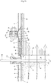
- an upstream side gas temperature sensor 109 (a downstream side gas temperature sensor 112) which is provided in the DPF 1, as shown in Fig. 1 and Fig. 12 .
- One end side of a cylindrical sensor boss body 110 is fixed by welding to the outer peripheral surface of the catalyst inside case 4, between the upstream side tube portion 4a and the downstream side tube portion 4b of the catalyst inside case 4.
- the other end side of the sensor boss body 110 is extended in a radial direction from a sensor attaching opening 5a of the catalyst outside case 5 toward the outer side of the case 5.
- a sensor attaching bolt 111 is attached by screw to the other end side of the sensor boss body 110.
- a thermistor type upstream side gas temperature sensor 109 is passed through the sensor attaching bolt 111, and the upstream side gas temperature sensor 109 is supported to the sensor boss body 110 via the sensor attaching bolt 111.
- a detecting portion of the upstream side gas temperature sensor 109 is protruded into the catalyst downstream side space 29.
- the exhaust gas temperature is detected by the upstream side gas temperature sensor 109.
- the thermistor type downstream side gas temperature sensor 112 is attached to the sensor boss body 110 via the sensor attaching bolt 111, and the temperature of the exhaust gas in the other side end face (the discharged side end face) 3b of the soot filter 3 is detected by the downstream side gas temperature sensor 112.
- the differential pressure sensor 63 is provided as the exhaust gas pressure sensor.
- the differential pressure sensor 63 is provided for detecting a pressure difference of the exhaust gas between the upstream side and the downstream side with reference to the soot filter 3 within the DPF 1. It is structured such that a piled-up amount of the particulate matter in the soot filter 3 is converted on the basis of the pressure difference, and a clogged state within the DPF 1 can be comprehended.
- a regeneration control of the soot filter 3 can be automatically executed, for example, by actuating an accelerator control means or an intake throttle control means which are not illustrated, on the basis of the pressure difference of the exhaust gas which is detected by the differential pressure sensor 63.
- a sensor bracket 66 is fastened by bolt to the inlet pinching flange 54 in the sound absorbing side, and the sensor bracket 66 is arranged in an upper surface side of the DPF casing 60.
- a detection main body 67 of the differential pressure sensor 63 is attached to the sensor bracket 66.
- a upstream side pipe joint body 64 and a downstream side pipe joint body 65 are respectively connected to the detection main body 67 of the differential pressure sensor 63 via an upstream side sensor piping 68 and a downstream side sensor piping 69.
- a sensor boss body 113 is arranged, in the same manner as the sensor boss body 110, in the DPF casing 60.
- the upstream side pipe joint body 64 (the downstream side pipe joint body 65) is fastened to the sensor boss body 113 by a pipe joint bolt 114.
- the sensor support portion 44 is integrally formed in a part of the inlet pinching flange 54 in the sound absorbing side, and the sensor bracket 66 is fastened to the sensor support portion 44 by a bolt 47.
- the inlet pinching flange 54 in the sound absorbing side (the flange body for attaching the exhaust gas purifying case) is detachably fastened to the outlet pinching flange 53 in the filter outlet side (the flange body for attaching the exhaust gas pressure sensor) via a bolt 42 and a nut 43.
- the sensor bracket 66 for attaching the exhaust gas pressure sensor is detachably provided in the sensor support portion 44, and the differential pressure sensor (the exhaust gas pressure sensor) 63 is arranged in the outer side surface of the filter outside case (the exhaust gas purifying case) 21.
- the sensor boss body 113 serving as the sensor piping body is provided in the catalyst inside case 4 (the filter inside case 20) serving as the exhaust gas purifying case.
- the upstream side pipe joint body 64 (the downstream side pipe joint body 65) for connecting the sensor piping is fastened to the sensor boss body 113 via the pipe joint bolt 114, and the upstream side sensor piping 68 (the downstream side sensor piping 69) made of a steel pipe is extended from the sensor boss body 113 toward the differential pressure sensor 67 serving as the exhaust gas pressure sensor, along the outer peripheral shape of the catalyst outside case 5 (the filter outside case 21) serving as the exhaust gas purifying case.
- the differential pressure sensor 67 is connected to the upstream side sensor piping 68 (the downstream side sensor piping 69) via an upstream side flexible pipe 137 (a downstream side flexible pipe 138) made of a rigid resin.
- the sensor boss body 113 is firmly fixed to the outer peripheral surface of the catalyst inside case 4 in the vicinity of the gas outflow side end face 2b of the diesel oxidation catalyst 2.
- One end side of the cylindrical sensor boss body 113 is fixed by welding to the outer peripheral surface of the catalyst inside case 4.
- the upstream side pipe joint body 64 is fastened to the sensor boss body 113 by the pipe joint bolt 114.
- the detection main body 67 of the differential pressure sensor 63 is connected to the upstream side pipe joint body 64 via the upstream side sensor piping 68.
- a sensor opening 4c which communicates a hollow portion of the sensor boss body 113 with the catalyst downstream side space 29 is formed in the catalyst inside case 4. It is structured such that the exhaust gas is discharged from the gas outflow side end face 2b of the diesel oxidation catalyst 2 to the catalyst downstream side space 29, whereby a part of the exhaust gas within the catalyst downstream side space 29 moves to the detection main body 67 side via the sensor opening 4c, the hollow portion of the sensor boss body 113, a hollow portion of the upstream side pipe joint body 64, and the upstream side sensor piping 68.
- the diesel oxidation catalyst 2 or the soot filter 3 which serves as the gas purifying body purifying the exhaust gas discharged from the diesel engine 70
- the catalyst inside case 4, the catalyst outside case 5, the filter inside case 20 and the filter outside case 21 which serve as the exhaust gas purifying case inward provided with the gas purifying body
- the differential pressure sensor 63 which serves as the exhaust gas pressure sensor detecting the exhaust gas pressure of the diesel oxidation catalyst 2 or the soot filter 3.
- the differential pressure sensor 63 is arranged in an outer side surface of the catalyst outside case 5 or the filter outside case 21.
- the sensor support portion 44 is integrally formed in a part of the inlet pinching flange 54 which serves as the flange body of the catalyst outside case 5 or the filter outside case 21, and the sensor bracket 66 for attaching the differential pressure sensor 63 is detachably provided in the sensor support portion 44. Accordingly, it is possible to support the differential pressure sensor 63 in the inlet pinching flange 54 having a high rigidity, and it is possible to reduce a vibration of the differential pressure sensor 63. It is possible to prevent the differential pressure sensor 63 from falling away. It is possible to easily secure a strength of the catalyst inside case 4 or the catalyst outside case 5 or the filter inside case 20 or the filter outside case 21 which constructs the DPF 1, or a support strength of the differential pressure sensor 63.
- the outlet pinching flange 53 which serves as the flange body for attaching the filter outside case 21 is detachably fastened to the inlet pinching flange 54 for attaching the differential pressure sensor 63. Accordingly, it is possible to support the differential pressure sensor 63 to the inlet pinching flange 54 having a high rigidity, and it is possible to reduce a vibration of the differential pressure sensor 63. It is possible to prevent the differential pressure sensor 63 from falling away. It is possible to easily secure the support strength of the exhaust gas purifying case, or the support strength of the differential pressure sensor 63.
- the sensor boss body 113 which serves as the sensor piping body is provided in the catalyst inside case 4 or the filter inside case 20
- the pipe joint bodies 64 and 65 for connecting the sensor pipings 68 and 69 are fastened to the sensor boss body 113 via the pipe joint bolt 114
- the sensor pipings 68 and 69 which are connected to the DPF 1 and the differential pressure sensor 63 are extended from the sensor boss body 113 toward the differential pressure sensor 63 along the outer peripheral shape of the catalyst outside case 5 or the filter outside case 21. Accordingly, the sensor pipings 68 and 69 can be compactly arranged in the outer periphery of the DPF 1.
- the sensor pipings 68 and 69 in an optional direction from the pipe joint bodies 64 and 65 toward the differential pressure sensor 63. It is possible to improve an assembling workability of the DPF 1 (the exhaust gas purifying case) to the diesel engine 70 or the like.
- a worker or a tool is hard to come into contact with the sensor pipings 68 and 69 or the like at a time of an assembling work or a maintenance work of the diesel engine 70 or the DPF 1, and it is possible to easily protect the sensor pipings 68 and 69 or the like. It is possible to improve a handling workability such as a carriage of the DPF 1.
- FIG. 21 is an enlarged cross sectional view showing an attaching portion of a sensor boss body according to the second embodiment.
- a catalyst inside case 4 is constructed by an upstream side tube portion 4a which accommodates a diesel oxidation catalyst 2, and a downstream side tube portion 4b to which a filter inside case 20 is inserted.
- the upstream side tube portion 4a is formed as a cylindrical shape having a smaller diameter than the downstream side tube portion 4b.
- the upstream side tube portion 4a and the downstream side tube portion 4b are integrally connected via a step portion 4c.
- a sensor boss body 110 is fixed by welding to an outer peripheral surface of the upstream side tube portion 4a which is positioned close to the step portion 4c in an outer peripheral surface of the upstream side tube portion 4a.
- the sensor boss body 110 can be firmly fixed to a high rigidity position of the upstream side tube portion 4a which is close to the step portion 4c, by utilizing the upstream side tube portion 4a.
- Gas temperature sensors 109 and 112 can be supported so as to be close to a gas outflow side end face 2b of the diesel oxidation catalyst 2.
- the upstream side tube portion 4a having the smaller diameter and the filter inside case 20 are formed as a cylindrical shape having the same diameter.
- FIG. 22 is an enlarged cross sectional view showing an attaching portion of a sensor boss body according to the third embodiment.
- a catalyst inside case 4 is constructed by an upstream side tube portion 4a which accommodates a diesel oxidation catalyst 2, and a downstream side tube portion 4b to which a filter inside case 20 is inserted.
- the upstream side tube portion 4a is formed as a cylindrical shape having a smaller diameter than the downstream side tube portion 4b.
- the upstream side tube portion 4a and the downstream side tube portion 4b are integrally connected via a step portion 4c.
- a sensor boss body 110 is fixed by welding to an outer peripheral surface of the upstream side tube portion 4a which is positioned close to the step portion 4c, and the step portion 4c, in an outer peripheral surface of the upstream side tube portion 4a.
- the sensor boss body 110 can be firmly fixed to a high rigidity position of the catalyst inside case 4, by utilizing the upstream side tube portion 4a and the step portion 4c. It is possible to reduce a mechanical vibration of gas temperature sensors 109 and 112.
- the upstream side tube portion 4a having the smaller diameter and the filter inside case 20 are formed as a cylindrical shape having the same diameter.
- FIG. 23 is an enlarged cross sectional view showing an attaching portion of a sensor boss body according to the fourth embodiment.
- a filter inside case 20 is constructed by an upstream side tube portion 20a to which a catalyst inside case 4 is inserted, and a downstream side tube portion 20b which accommodates a soot filter 3.
- the catalyst inside case 4 is formed as a cylindrical shape having a smaller diameter than the filter inside case 20.
- the catalyst inside case 4 and the filter inside case 20 are formed as a cylindrical shape having a straight ridge line, and are formed such that diameters in both end sides are equal.
- a sensor boss body 110 is firmly fixed to an upstream side tube portion 20a, and a gas temperature sensor 109 is protruded into the upstream side tube portion 20a which is a catalyst downstream side space 29.
- an end portion of the upstream side tube portion 20a is detachably fixed to an outer peripheral surface of the catalyst inside case 4, via junction flanges 25 and 26, in an upstream side of a gas outflow side end face 2b of the diesel oxidation catalyst 2.
- the fourth embodiment has the same effect as the first embodiment.
- Fig. 24 is an enlarged cross sectional view showing an attaching portion of a sensor boss body according to the fifth embodiment.
- Fig. 25 is an enlarged cross sectional view showing an attaching portion of a sensor boss body according to the sixth embodiment.
- a heat shield case 190 is provided in an outer surface of one of the catalyst inside case 4 in the catalyst inside case 4 or the filter inside case 20.
- the catalyst inside case 4 and the filter inside case 20 are formed as a cylindrical shape having the same diameter.
- the catalyst inside case 4 and the filter inside case 20 are formed as a cylindrical shape having a straight ridge line, and are formed such that diameters in both end sides are equal.
- a downstream side gap 23 which is the same as the first embodiment is formed between outer peripheral surfaces of the catalyst inside case 4 and the filter inside case 20, and an inner peripheral surface of the heat shield case 190.
- an upstream side of the heat shield case 190 is formed as a cylindrical shape having a smaller diameter than a downstream side, a small-diameter cylindrical upstream side end portion 190a of the heat shield case 190 is bonded to the outer peripheral surface of the catalyst inside case 4, and an upstream side of the heat shield case 190 is fixed by welding to the catalyst inside case 4.
- One end side of the heat shield case 190 is firmly fixed to an outer peripheral surface which is inside the downstream side end face of the one of the catalyst inside case 4.
- an upstream side (an exhaust gas intake side end portion) of the other of the filter inside case 20 is inserted into the heat shield case 190.
- a catalyst downstream side space 29 which is the same as the first embodiment is formed between a gas outflow side end face 2b of the diesel oxidation catalyst 2 within the catalyst inside case 4, and one side end face (an intake side end face) 3a of the soot filter 3 within the filter inside case 20.
- the inside cases 4 and 20, the heat shield case 190 and the catalyst outside case 5 are provided as a three-layer structure, a downstream side end of the heat shield case 190 is formed shorter than a downstream side end of the catalyst outside case 5, and a downstream side end of the catalyst inside case 4 is formed shorter than a downstream side end of the heat shield case.
- one end side (an upstream side) of the heat shield case 190 is fitted to the one of the catalyst inside case 4, and the other end side of the heat shield case is connected by welding to a catalyst side junction flange 25 which serves as a flange body for bonding the outside cases 5 and 21.
- a sensor attaching opening 5a of the catalyst outside case 5 is occluded by the heat shield case 190.
- the other end side (a downstream side) of the heat shield case 190 which is extended to the outer surface of the other of the filter inside case 20 is connected to the catalyst side junction flange 25 which serves as the flange body for bonding the outside cases 5 and 21.
- a downstream side gap 23 which serves as a space is formed between an outer peripheral side of the other of the filter inside case 20 to which the other end side (the downstream side) of the heat shield case 190 is extended, and an inner peripheral side of the heat shield case 190.
- a sensor boss body 113 or 110 is firmly attached to an outer peripheral surface of the heat shield case 190 in the vicinity of the end face of the one of the catalyst inside case 4.
- An inner diameter of a firmly attaching position of the sensor boss body 113 or 110 in the heat shield case 190 is formed larger than an outer diameter of the catalyst inside case 4 (the filter inside case 20).
- an upstream side gap 23a is formed between the catalyst inside case 4 and the heat shield case 190, in an upstream side of a downstream side end portion of the catalyst inside case 4.
- One end side of the cylindrical sensor boss body 113 is fixed by welding to an outer peripheral surface in an upstream side of the heat shield case 190.
- An upstream side pipe joint body 64 is fastened to the sensor boss body 113 by a pipe joint bolt 114.
- a detection main body 67 of the differential pressure sensor 63 is connected to the upstream side pipe joint body 64 via an upstream side sensor piping 68.
- a sensor opening 190b which communicates a hollow portion of the sensor boss body 113 is formed in an upstream side gap 23a. It is structured such that an exhaust gas is discharged from the gas outflow side end face 2b of the diesel oxidation catalyst 2 to the catalyst downstream side space 29, whereby a part of the exhaust gas within the catalyst downstream side space 29 moves to a detection main body 67 side via the upstream side gap 23a, the sensor opening 190b, the hollow portion of the sensor boss body 113, the hollow portion of the upstream side pipe joint body 64 and the upstream side sensor piping 68.
- the exhaust gas is supplied to the sensor opening 190b from the otherof the upstream side gap 23a, even if the particulate matter is piled up in a part of the upstream side gap 23a between the catalyst inside case 4 and the heat shield case 190.
- one end side of the cylindrical sensor boss body 110 is fixed by welding to an outer peripheral surface of the heat shield case 190 (a position at which the catalyst downstream side space 29 is formed).
- the other end side of the sensor boss body 110 is extended in a radial direction from the sensor attaching opening 5a of the catalyst outside case 5 toward an outer side of the case 5.
- a sensor attaching bolt 111 is attached by screw to the other end side of the sensor boss body 110.
- a thermistor type upstream side gas temperature sensor 109 is passed through the sensor attaching bolt 111, and the upstream side gas temperature sensor 109 is supported to the sensor boss body 110 via the sensor attaching bolt 111.
- a detecting portion of the upstream side gas temperature sensor 109 is protruded into the catalyst downstream side space 29.
- the sensor boss body 110 can be arranged in the outer peripheral surface of the heat shield case 190 in such a manner as to make the upstream side gas temperature sensor 109 close to the gas outflow side end face 2b until being in contact with the gas outflow side end face 2b of the diesel oxidation catalyst 2.
- a diesel oxidation catalyst 2 or a soot filter 3 which purifies the exhaust gas discharged from the diesel engine 70
- a catalyst inside case 4 or a filter inside case 20 which is inward provided with the diesel oxidation catalyst 2 or the soot filter 3
- a catalyst outside case 5 or a filter outside case 21 which is inward provided with the catalyst inside case 4 or the filter inside case 20.
- an outlet end portion (a gas outflow side end portion) of the catalyst inside case 4 in an exhaust upstream side and an inlet end portion (a gas intake side end portion) of the filter inside case 20 in an exhaust downstream side are overlapped as a double structure
- sensor boss bodies 110 and 113 for supporting the exhaust gas sensor are arranged in an outer surface of an outlet end portion or an inlet end portion of the double structure, and the sensor boss bodies 110 and 113 are extended to an outer side of the catalyst outside case 5.
- a differential pressure sensor (an exhaust gas pressure sensor) 63, and an upstream side gas temperature sensor (an exhaust gas temperature sensor) 109 are provided as the exhaust gas sensor.
- the piping 68 of the upstream side gas temperature sensor 109 (the exhaust gas temperature sensor) or the differential pressure sensor 63 (the exhaust gas pressure sensor), via the sensor boss bodies 110 and 113. Further, it is possible to easily reduce the lowering of the exhaust gas temperature within the catalyst inside case 4 or the filter inside case 20, on the basis of a heat insulating (a heat keeping) action of the catalyst outside case 5 or the filter outside case 21. It is possible to reduce a stay of the particulate matter in the exhaust gas in the inner portion of the soot filter 3 by maintaining the exhaust gas temperature in the filter inside case 20, it is not necessary to regenerate the soot filter 3 at a high frequency, and it is possible to improve a purifying performance of the exhaust gas.
- the heat shield case 190 is provided in the outer surface of the one of the catalyst inside case 4, the other of the filter inside case 20 is inserted into the heat shield case 190, one end side of the heat shield case 190 is firmly fixed to an outer peripheral surface which is in an inner side than the end face of the one of the catalyst inside case 4, and the sensor boss body 110 is firmly fixed to an outer peripheral surface of the heat shield case 190 in the vicinity of the end face of the one of the catalyst inside case 4.
- the catalyst outside case 5 and the heat shield case 190 can be extended to a position at which the diesel oxidation catalyst 2 and the soot filter 3 are opposed, and it is possible to easily maintain the exhaust gas temperature within the filter inside case 20 by the catalyst outside case 5 and the heat shield case 190. Further, it is possible to make a distance L2 between the opposed diesel oxidation catalyst 2 and the soot filter 3 as a shortest dimension, while it is possible to form the catalyst inside case 4 and the filter inside case 20 at the same diameter.
- the downstream side gap 23 is formed between the heat shield case 190 and the filter inside case 20 which is inward inserted to the heat shield case 190, whereby it is possible to easily extract the filter inside case 20 from the heat shield case 190. Further, it is possible to improve a heat insulating property of the position at which the diesel oxidation catalyst 2 and the soot filter 3 are opposed, by the heat shield case 190 and the catalyst outside case 5. It is possible to easily maintain the oxidizing process temperature (the regenerating temperature) of the particulate matter in the exhaust gas which the soot filter 3 collects.
- the sensor attaching opening 5a (the sensor attaching hole) of the catalyst outside case 5 is occluded by the heat shield case 190, it is possible to make the sensor boss bodies 110 and 113 protrude to the outer direction of the catalyst outside case 5 so as to easily connect the upstream side sensor piping 68 of the differential pressure sensor 63 or the upstream side gas temperature sensor 109 (the exhaust gas sensor) to a measuring portion. It is possible to easily extend an electric wiring and a piping from the side of the sensor boss bodies 110 and 113. Further, it is possible to easily prevent the exhaust gas within the catalyst inside case 4 or the filter inside case 20 from leaking out of the sensor attaching opening 5a. It is possible to reduce a rise of the surface temperature of the catalyst outside case 5 or the filter outside case 21.
- a side end of the heat shield case 190 is formed shorter than a side end of the catalyst outside case 5 (the filter outside case 21), and a side end of the catalyst inside case 4 (the filter inside case 20) is formed shorter than a side end of the heat shield case 190, it is possible to reduce the lowering of the exhaust gas temperature, and it is possible to improve a processing efficiency of the particulate matter in the exhaust gas. It is possible to reduced the rise of the surface temperature of the catalyst outside case 5 (the filter outside case 21), and it is possible to improve a workability of a maintenance or the like of the diesel engine 70 which is required during its operation.
Description
- The present invention relates to an exhaust gas purifying device which is mounted to a diesel engine or the like, and more particularly to an exhaust gas purifying device which removes a particulate matter (a soot and a particulate) and the like which are included in an exhaust gas.
- Conventionally, there has been known a technique which is provided in an exhaust route of a diesel engine with a diesel particulate filter (hereinafter, refer to as DPF) as an exhaust gas purifying device (an after treatment devcice), for purifying an exhaust gas which is discharged form the diesel engine by the DPF (refer, for example, to patent document 1).
- Further, in the DPF, there has been also known a technique which is provided with a temperature sensor which detects a temperature of an exhaust gas discharged from a diesel engine, and a pressure sensor which detects a pressure of the exhaust gas discharged from the diesel engine (refer, for example, to patent
documents 1 and 2). - Further, in the DPF, there has been known a technique which is provided with an inside case as a double structure in an inner portion of an outside case, and is inward provided with an oxidation catalyst or a soot filter in the inside case (refer, for example, to patent document 3).
- Further, in the DPF, there has been known a technique which couples a case having an oxidation catalyst therein, and a case having a soot filter therein, so as to be separable via a flange which is fastened by a bolt (refer, for example, to patent
documents 4 to 5).
Patent document 6 discloses an access joint for an engine exhaust system, wherein the access joint includes first and second exhaust conduits each having a conduit body and a flange unitary with the conduit body. The flanges have first surfaces that face towards one another and second surfaces that face away from one another. The joint also includes a clamp having a channel that receives the flanges and that compresses the flanges toward one another when the clamp is tightened. - Further,
patent document 7 teaches an automotive exhaust gas system having a catalytic converter or a diesel particle filter with a substrate filter insert embedded within a double walled housing. The housing inner face clamps the substrate and the outer housing clamps the inner housing such that the housing and the substrate form a single entity. -
- Patent Document 1:
JP 2004-263593 - Patent Document 2:
JP 2001-73748 - Patent Document 3:
JP 2005-194949 - Patent Document 4:
JP 2009-228516 - Patent Document 5:
JP 2009-91982 - Patent Document 6:
US 2006/053779 A1 - Patent Document 7:
DE 10 2005 019 182 A1 - In the prior art, in the case of arranging the exhaust gas temperature sensor which detects the temperature of the exhaust gas discharged form the diesel engine, and the exhaust gas pressure sensor which detects the pressure of the exhaust gas, in the structure which couples the single structure case inward provided with the oxidation catalyst, and the single structure case inward provided with the soot filter, the exhaust gas temperature in the inner portion of the case tends to be lowered, and an outer surface of the case tends to come to a high temperature, by forming a support portion of the exhaust gas temperature sensor and a pickup portion of the exhaust gas for detecting the pressure in the single structure case between the oxidation catalyst and the soot filter.
- In other words, since the exhaust gas temperature in the inner portion of the case is lowered, the particulate matter in the exhaust gas tends to clog the soot filter, and it is necessary to regenerate the soot filter at a high frequency, so that there is such a problem that it is impossible to improve a purifying performance of the exhaust gas. On the other hand, since the outer surface of the case comes to a high temperature, it is necessary to carry out a maintenance of the diesel engine after the case is cooled down, so that there is such a problem that it is impossible to improve a handling workability.
- Further, in the prior art, since it is necessary to evaluate an initial setting (adjusting) condition of the exhaust gas pressure sensor per plural specifications of engines or machine bodies, in the case that the exhaust gas pressure sensor for detecting the pressure of the exhaust gas is provided in the engine or the machine body side, there is such a problem that it is impossible to reduce an evaluating man power for a design of assembling the DPF to the engine, a test and the like. It is not necessary to evaluate the DPF for each of the plural specifications of engines, by arranging the exhaust gas pressure sensor in the DPF, however, there is such a problem that it is impossible to easily secure a strength of the exhaust gas purifying case which constructs the DPF, or a support strength of the exhaust gas pressure sensor.
- On the other hand, it is necessary to connect the exhaust gas pressure sensor to the DPF, thereafter connect a sensor piping to the DPF and the exhaust gas pressure sensor, and communicate the exhaust gas pressure sensor to the DPF. There is such a problem that it is impossible to easily simplify an assembling work of the exhaust gas purifying case to the engine or the like. Further, in the structure in which the sensor piping connecting the exhaust gas pressure sensor to the DPF is extended to the engine or the machine body side from the DPF, a worker or a tool tends to come into contact with the sensor piping at a time of an assembling work or a maintenance work of the engine and the DPF, so that there is such a problem that it is impossible to easily protect the sensor piping or the like, and it is impossible to improve a handling workability.
- Accordingly, the present invention intends to provide an exhaust gas purifying device to which an improvement is applied by making a study of these actual conditions.
- The present invention relates to the exhaust gas purifying device of
claim 1. Preferred embodiments are defined in thedependent claims 2 to 4. According to a first aspect as defined inclaim 1, there is provided an exhaust gas purifying device comprising: a plurality of gas purifying bodies which purifies an exhaust gas discharged by an engine; a plurality of inside cases which is inward provided with the respective gas purifying bodies; and outside cases which are inward provided with respective the inside cases, wherein an outlet end portion of the inside case in an exhaust gas upstream side and an inlet end portion of the inside case in an exhaust gas downstream side are superposed as a double structure, a sensor boss body for supporting an exhaust gas sensor is arranged in an outside surface of the outlet end portion or the inlet end portion of the double structure, and the sensor boss body is extended to an outside direction of the outside case. - According to a second aspect, in the exhaust gas purifying device described in the first aspect, a heat shield case is provided in an outside surface of one of the inside case, the other of the inside case is inserted into the heat shield case, one end side of the heat shield case is firmly fixed to an outer peripheral surface in an inner side than an end surface of the one of the inside case, and the sensor boss body is firmly fixed to an outer peripheral surface of the heat shield case in the vicinity of the end surface of the one of the inside case.
- According to a third aspect, in the exhaust gas purifying device described in the second aspect, an inner diameter of a firmly fixing position of the sensor boss body in the heat shield case is formed larger than an outer diameter of the inside case.
- According to a fourth aspect, in the exhaust gas purifying device described in the second aspect, one end side of the heat shield case is fitted to the inside case, and the other end side of the heat shield case is coupled to a flange body for bonding the outside cases.
- According to a fifth aspect, in the exhaust gas purifying device described in the second aspect, a sensor attaching hole of the outside case is occluded by the heat shield case.
- According to a sixth aspect, in the exhaust gas purifying device described in the second aspect, a space is formed between an outer peripheral side of the other of the inside case in which the other end side of the heat shield case is extended, and an inner peripheral side of the heat shield case.
- According to a seventh aspect, in the exhaust gas purifying device described in the second aspect, the other end side of the heat shield case which is extended to the outside surface of the other of the inside case is coupled to a flange body for connecting the outside case.
- According to an eighth aspect, in the exhaust gas purifying device described in the second aspect, the inside case, the heat shield case and the outside case are provided as a three-layer structure, a side end of the heat shield case is formed shorter than a side end of the outside case, and a side end of the inside case is formed shorter than a side end of the heat shield case.
- According to a ninth aspect as defined in
claim 2, in the exhaust gas purifying device described in the first aspect, the exhaust gas pressure sensor is arranged in an outside surface of the outside case, a pipe joint body for connecting the sensor piping is fastened to the sensor boss body via a pipe joint bolt, and the exhaust gas pressure sensor is connected to the sensor boss body via the sensor piping. - According to a tenth aspect as defined in
claim 3, in the exhaust gas purifying device described in the ninth aspect, a sensor support portion is integrally formed in a part of a flange body for pinching in the outside case, and a sensor bracket for attaching the exhaust gas pressure sensor is detachably provided in the sensor support portion. - According to an eleventh aspect as defined in
claim 4, in the exhaust gas purifying device described in the ninth aspect, the sensor piping is extended from the sensor piping body toward the exhaust gas pressure sensor, along an outer peripheral shape of the exhaust gas purifying case. - According to the first aspect, in the exhaust gas purifying device which is provided with the plurality of gas purifying bodies which purifies the exhaust gas discharged by the engine, the plurality of inside cases which is inward provided with the respective gas purifying bodies, and the outside case which are inward provided with the respective inside cases, the outlet end portion of the inside case in the exhaust gas upstream side and the inlet end portion of the inside case in the exhaust gas downstream side are superposed as the double structure, the sensor boss body for supporting the exhaust gas sensor is arranged in the outside surface of the outlet end portion or the inlet end portion of the double structure, and the sensor boss body is extended to the outside direction of the outside case. Accordingly, it is possible to easily assemble the pipings of the exhaust gas temperature sensor and the exhaust gas pressure sensor and the like via the sensor boss body. Further, it is possible to easily reduce the lowering of the exhaust gas temperature within the inside case on the basis of a heat insulating (a heat keeping) action of the outside case. It is possible to reduce a stay of the particulate matter in the exhaust gas in the inner portion of the gas purifying body (the soot filter) by maintaining the exhaust gas temperature in the inner portion of the inside case, whereby it is not necessary to regenerate the gas purifying body at a high frequency, and it is possible to improve a purifying performance of the exhaust gas. On the other hand, since a rise of an outer surface temperature of the outside case is suppressed, it is possible to carry out a maintenance of the engine before the engine or the like is cooled, and it is possible to improve a handling workability.
- According to the second aspect, the heat shield case is provided in the outside surface of the one of the inside case, the other of the inside case is inserted into the heat shield case, the one end side of the heat shield case is firmly fixed to the outer peripheral surface in the inner side than the end surface of the one of the inside case, and the sensor boss body is firmly fixed to the outer peripheral surface of the heat shield case in the vicinity of the end surface of the one of the inside case. Accordingly, it is possible to extend the outside case and the heat shield case to the position at which the gas purifying bodies are opposed, and it is possible to easily maintain the exhaust gas temperature in the inner portion of the inside case by the outside case and the heat shield case. Further, it is possible to make a distance between the opposed gas purifying bodies at a shortest dimension while forming the inside cases in the same diameter. In other words, in comparison with the conventional structure in which the expanded portion is provided, it is possible to form the distance between the gas purifying body end surface and the attaching position of the exhaust gas sensor at a shortest dimension (0 or an optional dimension) without being affected by an expansion margin of the inside case, a radius and a welding margin of the sensor boss body and the like. As a result, it is possible to shorten a whole length of the exhaust gas purifying device (DPF) and it is possible to easily mount the DPF on various equipment. It is possible to make the exhaust gas sensor close to the end surface of the gas purifying body until it comes into contact with the end surface of the gas purifying body, and it is possible to improve a control performance of an automatic regeneration or the like of the DPF.
- According to the third aspect, the inner diameter of the firmly fixing position of the sensor boss body in the heat shield case is formed larger than the outer diameter of the inside case. Accordingly, since a gap is formed between the heat shield case and the inside case which is inward inserted to the heat shield case, it is possible to easily extract the heat shield case and the inside case. Further, it is possible to improve a heat insulating property of the opposed position of the gas purifying bodies, by the heat shield case and the outside case. It is possible to easily maintain a treating temperature of the particulate matter which the gas purifying body collects.
- According to the fourth aspect, the one end side of the heat shield case is fitted to the inside case, and the other end side of the heat shield case is coupled to the flange body for bonding the outside cases. Accordingly, it is possible to support the heat shield case at a high rigidity by the inside case and the flange body. It is possible to easily prevent the exhaust gas within the inside case from leaking from the gap with the heat shield case toward the outside case. It is possible to reduce a rise of a surface temperature of the outside case.
- According to the fifth aspect, the sensor attaching hole of the outside case is occluded by the heat shield case. Accordingly, it is possible to easily couple the exhaust gas sensor to a measuring portion by making the sensor boss body protrude to an outside direction of the outside case. It is possible to easily extend an electric wiring, a piping and the like from the sensor boss body side. Further, it is possible to easily prevent the exhaust gas within the inside case from leaking from the sensor attaching hole. It is possible to reduce a rise of the surface temperature of the outside case.
- According to the sixth aspect, the space is formed between the outer peripheral side of the other of the inside case in which the other end side of the heat shield case is extended, and the inner peripheral side of the heat shield case. Accordingly, it is possible to easily make the other of the inside case come in and out with respect to the heat shield case, and it is possible to easily bond or separate the inside cases and the outside cases. It is possible to improve a maintenance workability of the gas purifying bodies or the exhaust gas sensor.
- According to the seventh aspect, the other end side of the heat shield case which is extended to the outside surface of the other of the inside case is coupled to the flange body for connecting the outside case. Accordingly, it is possible to easily prevent the exhaust gas from leaking from the gas purifying body toward the outside case. On the basis of the heat insulating action of the outside case and the heat shield case, it is possible to reduce the lowering of the exhaust gas temperature of the gas purifying body and the rise of the surface temperature of the outside case.
- According to the eighth aspect, the inside case, the heat shield case and the outside case are provided as the three-layer structure, the side end of the heat shield case is formed shorter than the side end of the outside case, and the side end of the inside case is formed shorter than the side end of the heat shield case. Accordingly, it is possible to reduce the temperature lowering of the exhaust gas, and it is possible to improve a treating efficiency of the particulate matter in the exhaust gas. It is possible to reduce the rise of the surface temperature of the outside case, and it is possible to improve a workability of a maintenance of a diesel engine which is necessary during an operation.
- According to the ninth aspect, the exhaust gas pressure sensor is arranged in the outside surface of the outside case, the pipe joint for connecting the sensor piping is fastened to the sensor boss body via the pipe joint bolt, and the exhaust gas pressure sensor is connected to the sensor boss body via the sensor piping. Accordingly, it is not necessary to evaluate an initial setting (adjusting) condition of the exhaust gas pressure sensor per the plural specifications of engines or machine bodies. It is possible to reduce an evaluating man power for a design, a test and the like of assembling the DPF in the engine. Since it is not necessary to evaluate the DPF for each of the plural specifications of engines by arranging the exhaust gas pressure sensor in the DPF, it is possible to reduce a manufacturing cost by standardizing the constructing parts relevant to the DPF, and reducing the number of the constructing parts relevant to the DPF. It is not necessary to evaluate the exhaust gas pressure sensor per the plural specifications of engines and machine bodies, and it is possible to improve a detecting precision of the exhaust gas pressure sensor as well as reducing a development cost.
- According to the tenth aspect, the sensor support portion is integrally formed in the part of the flange body for pinching in the outside case, and the sensor bracket for attaching the exhaust gas pressure sensor is detachably provided in the sensor support portion. Accordingly, it is possible to support the exhaust gas pressure sensor to the flange body having a high rigidity, and it is possible to reduce a vibration of the exhaust gas pressure sensor. It is possible to prevent the exhaust gas pressure sensor from falling away. It is possible to easily secure a strength of the exhaust gas purifying case which constructs the DPF, or a support strength of the exhaust gas pressure sensor.
- According to the eleventh aspect, the sensor piping is extended from the sensor piping body toward the exhaust gas pressure sensor, along the outer peripheral shape of the exhaust gas purifying case. Accordingly, it is possible to compactly arrange the sensor piping to an outer periphery of the DPF. Further, it is possible to extend the sensor piping in an optional direction from the pipe joint body toward the exhaust gas pressure sensor. It is possible to improve an assembling workability of the exhaust gas purifying case to the engine or the like. In comparison with the conventional structure in which the sensor piping is extended from the DPF to the engine or the machine body side, the worker or the tool is hard to come into contact with the sensor piping or the like at a time of the assembling work and the maintenance work of the engine and the DPF, and it is easily protect the sensor piping or the like. It is possible to improve a handling workability of a carriage of the DPF.
-
-
Fig. 1 is a cross sectional explanatory view of a DPF and shows a first embodiment; -
Fig. 2 is a perspective view of an outer appearance of the DPF; -
Fig. 3 is a plan view of the outer appearance of the DPF; -
Fig. 4 is a bottom elevational view of the outer appearance of the DPF; -
Fig. 5 is a front elevational view of the outer appearance of the DPF; -
Fig. 6 is a side elevational view of the outer appearance of the DPF; -
Fig. 7 is a cross sectional side view of an upstream side of the DPF; -
Fig. 8 is a cross sectional side view of a downstream side of the DPF; -
Fig. 9 is an exploded cross sectional explanatory view of the DPF; -
Fig. 10 is a separated side elevational view of a pinching flange (a semicircular arc body); -
Fig. 11 is an enlarged cross sectional view of a catalyst side junction flange; -
Fig. 12 is an enlarged cross sectional view showing an attaching portion of a sensor boss body for a gas temperature sensor; -
Fig. 13 is a plan view of a diesel engine which is provided with the DPF; -
Fig. 14 is a back elevational view of the diesel engine which is provided with the DPF; -
Fig. 15 is a left side view of the diesel engine which is provided with the DPF; -
Fig. 16 is a right side view of the diesel engine which is provided with the DPF; -
Fig. 17 is a back elevational perspective view of the diesel engine which is provided with the DPF; -
Fig. 18 is a plan perspective view of the diesel engine which is provided with the DPF; -
Fig. 19 is a partly enlarged view inFig. 18 ; -
Fig. 20 is an enlarged cross sectional view showing an attaching portion of a sensor boss body for a differential pressure sensor; -
Fig. 21 is an enlarged cross sectional view showing an attaching portion of a sensor boss body according to a second embodiment; -
Fig. 22 is an enlarged cross sectional view showing an attaching portion of a sensor boss body according to a third embodiment; -
Fig. 23 is an enlarged cross sectional view showing an attaching portion of a sensor boss body according to a fourth embodiment; -
Fig. 24 is an enlarged cross sectional view showing an attaching portion of a sensor boss body according to a fifth embodiment which is presently not claimed; and -
Fig. 25 is an enlarged cross sectional view showing an attaching portion of a sensor boss body according to a sixth embodiment which is presently not claimed. - A description will be given below of a first embodiment of an exhaust gas purifying device obtained by embodying the present invention on the basis of the accompanying drawings with reference to
Fig. 1 to Fig. 20 . It is provided with a continuous regeneration type diesel particulate filter 1 (hereinafter, refer to as DPF 1) as an exhaust gas purifying device. It is structured such that theDPF 1 reduces a carbon monoxide (CO) and a hydro carbon (HC) in an exhaust gas of adiesel engine 70, in addition to a removal of a particulate matter (PM) in the exhaust gas of thediesel engine 70. - As shown in
Fig. 1 ,Fig. 6 andFig. 13 , theDPF 1 serving as the exhaust gas purifying device is provided for collecting the particulate matter (PM) in the exhaust gas. TheDPF 1 is structured as an approximately cylindrical shape which extends long in a lateral direction which intersects an output shaft (a crank shaft) of thediesel engine 70 in a plan view. TheDPF 1 is arranged on aflywheel housing 78 of thediesel engine 70. Both left and right sides (one end side and the other end side in a moving direction of the exhaust gas) of theDPF 1 are provided with an exhaust gas inlet pipe 16 (an exhaust gas intake side), and an exhaust gas outlet pipe 34 (an exhaust gas discharge side) so as to be sorted to left and right sides of thediesel engine 70. The exhaustgas inlet pipe 16 in the exhaust gas intake side of theDPF 1 is detachably fastened by bolt to anexhaust manifold 71 of thediesel engine 70. A tail pipe 107 is connected to the exhaustgas outlet pipe 34 in the exhaust gas discharge side of theDPF 1. - As shown in
Fig. 1 to Fig. 6 , theDPF 1 is structured such that adiesel oxidation catalyst 2, for example, a platinum or the like and asoot filter 3 of a honeycomb structure are accommodated in series side by side in aDPF casing 60 made of a heat resisting metal material, via cylindricalinside cases DPF 1 is attached to aflywheel housing 78 via a flangeside bracket leg 61 and a casingside bracket leg 62 serving as a support body. In this case, one end side of the flangeside bracket leg 61 is detachably fastened by bolt to an outer peripheral side of theDPF casing 60 via aflange 26 mentioned later. One end side of the casingside bracket leg 62 is integrally fixed by welding to an outer peripheral surface of theDPF casing 60. - On the other hand, as shown in
Figs. 1 to 6 andFig. 13 , the other end side of the flangeside bracket leg 61 is detachably fastened to an upper surface (a DPF attaching portion) of theflywheel housing 78 by two after attachingbolts 88. The other end side of the casingside bracket leg 62 is detachably fastened to the upper surface (the DPF attaching portion) of theflywheel housing 78 by a before attachingbolt 87 and the after attachingbolt 88. Anotch hole 89 for engaging and inserting the before attachingbolt 87 is formed in the other end side of the casingside bracket leg 62. - In other words, in the case that the
DPF 1 is assembled in thediesel engine 70, first of all, the before attachingbolt 87 is incompletely screwed to the upper surface of theflywheel housing 78. Further, a worker lifts up theDPF 1 by both hands, locks the casingside bracket leg 62 to the before attachingbolt 87 via thenotch hole 89, and temporarily fastens theDPF 1 to thediesel engine 70. The worker can unlink both the hands from theDPF 1 in this state. Thereafter, aninlet flange body 17 is fastened to theexhaust manifold 71, and the exhaustgas inlet pipe 16 is firmly fixed to theexhaust manifold 71. - On the other hand, the flange
side bracket leg 61 and the casingside bracket leg 62 are fastened to the upper surface of theflywheel housing 78 by three after attachingbolts 88. Further, the before attachingbolt 87 is completely fastened, and theDPF 1 is detachably firmly fixed to the upper surface of theflywheel housing 78. In this case, theDPF 1 can be detached in accordance with an inverse procedure to the above. As a result, theDPF 1 can be stably coupled and supported to a rear portion of thediesel engine 70, in an upper portion of theflywheel housing 78 which is a high rigidity member, by thebracket legs exhaust manifold 71. Further, it is possible to execute an attaching and detaching work of theDPF 1 to and from thediesel engine 70 by only one worker. - The structure mentioned above, the exhaust gas of the
diesel engine 70 flows into thediesel oxidation catalyst 2 side within theDPF casing 60 from theexhaust manifold 71 of thediesel engine 70, and moves from thediesel oxidation catalyst 2 to thesoot filter 3 side so as to be purified. The particulate matter in the exhaust gas can not pass through a porous shaped partition wall between cells in thesoot filter 3. In other words, the particulate matter in the exhaust gas is collected in thesoot filter 3. Thereafter, the exhaust gas passing through thediesel oxidation catalyst 2 and thesoot filter 3 is discharged to the tail pipe 107. - Since a temperature of the exhaust gas goes beyond a regenerable temperature (for example, about 300°C) at a time when the exhaust gas passes through the
diesel oxidation catalyst 2 and thesoot filter 3, NO (a nitrogen monoxide) in the exhaust gas is oxidized into an unstable NO2 (a nitrogen dioxide) on the basis of an action of thediesel oxidation catalyst 2. Further, the particulate matter which is picked up by thesoot filter 3 is oxidized and removed by O (an oxygen) which is discharged at a time when NO2 is returned to NO. In the case that the particulate matter is piled up in thesoot filter 3, the particulate matter is oxidized and removed by retaining the temperature of the exhaust gas equal to or higher than the regenerable temperature. Therefore, a particulate matter collecting capacity of thesoot filter 3 is recovered (thesoot filter 3 is regenerated). - A description will be given of a structure which assembles the
diesel oxidation catalyst 2 corresponding to one example of an exhaust gas purifying body (a filter) which purifies the exhaust gas discharged by thediesel engine 70, with reference toFig. 1 andFig. 9 . Thediesel oxidation catalyst 2 is provided within an approximately cylindrical catalyst insidecase 4 made of a heat resisting metal material. The catalyst insidecase 4 is provided within an approximately cylindrical catalyst outsidecase 5 made of a heat resisting metal material. In other words, the catalyst insidecase 4 is fitted to an outer side of thediesel oxidation catalyst 2 via a mat shaped catalystheat insulating material 6 made of a ceramic fiber. The catalystheat insulating material 6 is pressure inserted between thediesel oxidation catalyst 2 and the catalyst insidecase 4, thereby protecting thediesel oxidation catalyst 2. - Further, the catalyst outside
case 5 is fitted to an outer side of the catalyst insidecase 4 via asupport body 7 constructed by an end face L-shaped thin plate. The catalyst outsidecase 5 is one of elements which construct theDPF casing 60 mentioned above. In this case, thediesel oxidation catalyst 2 is protected by the catalystheat insulating material 6. A stress (a mechanical vibration and a deforming force) of the catalyst outsidecase 5 which is transmitted to the catalyst insidecase 4 is lowered by thesupport body 7 constructed by the thin plate. - As shown in
Fig. 1 andFig. 9 , a discoidside lid body 8 is firmly fixed to one side end portion of the catalyst insidecase 4 and the catalyst outsidecase 5 by welding. Anouter lid body 9 is fastened to an outer surface side of theside lid body 8 by a bolt and a nut. A gas inflowside end surface 2a of thediesel oxidation catalyst 2 and theside lid body 8 are spaced only at a fixed distance L1 (a gas inflow space 11). The exhaustgas inflow space 11 is formed between the gas inflowside end surface 2a of thediesel oxidation catalyst 2 and theleft lid body 8. An exhaustgas inflow port 12 which faces to the exhaustgas inflow space 11 is opened to the catalyst insidecase 4 and the catalyst outsidecase 5. Anocclusion ring body 15 is firmly fixed in a pinching manner between an opening edge of the catalyst insidecase 4 and an opening edge of the catalyst outsidecase 5. Since a gap between the opening edge of the catalyst insidecase 4 and the opening edge of the catalyst outsidecase 5 is closed by theocclusion ring body 15, it is possible to prevent the exhaust gas from flowing into between the catalyst insidecase 4 and the catalyst outsidecase 5. - As shown in
Figs. 1 to 6 andFig. 9 , an exhaustgas inlet pipe 16 is arranged in an outer surface of the catalyst outsidecase 5 in which the exhaustgas inflow port 12 is formed. Theinlet flange body 17 is fixed by welding to one opening end portion of the exhaustgas inlet pipe 16. Theinlet flange body 17 is detachably fastened by bolt to theexhaust manifold 71 of thediesel engine 70. The one opening end portion of the exhaustgas inlet pipe 16 is communicated with theexhaust manifold 71. The other opening end portion of the exhaustgas inlet pipe 16 is welded to the outer surface of the catalyst outsidecase 5 in such a manner as to cover the exhaustgas inflow port 12 from an outer side. In this case, a pair of reinforcingbracket bodies 18 is fixed by welding between the outer surface of the catalyst outsidecase 5 and the side edge of theinlet flange body 17, and a coupling strength between theexhaust manifold 71 and the exhaustgas inlet pipe 16 is secured. - In the structure mentioned above, the exhaust gas of the
diesel engine 70 enters into the exhaustgas inlet pipe 16 from theexhaust manifold 71, enters into the exhaustgas inflow space 11 from the exhaustgas inlet pipe 16 via the exhaustgas inflow port 12, and is supplied to thediesel oxidation catalyst 2 from the gas inflowside end surface 2a in a left side thereof. The nitrogen dioxide (NO2) is generated on the basis of the oxidizing action of thediesel oxidation catalyst 2. - A description will be given of a structure which assembles the
soot filter 3 corresponding to one example of the exhaust gas purifying body (the filter) which purifies the exhaust gas discharged by thediesel engine 70 with reference toFig. 1 andFig. 9 . Thesoot filter 3 is provided within a filter insidecase 20 which is made of a heat resisting metal material and is formed as an approximately cylindrical shape. The filter insidecase 20 is provided within a filter outsidecase 21 which is made of a heat resisting metal material and is formed as an approximately cylindrical shape. In other words, the filter insidecase 20 is fitted to an outer side of thesoot filter 3 via a filterheat insulating material 22 which is made of a ceramic fiber and is formed as a mat shape. The filter outsidecase 21 is one of the elements which construct theDPF casing 60 mentioned above together with the catalyst outsidecase 5. In this case, the filterheat insulating material 22 is pressure inserted between thesoot filter 3 and the filter insidecase 20 so as to protect thesoot filter 3. - As shown in
Fig. 1 andFig. 9 , the catalyst insidecase 4 which is formed as a cylindrical shape having a straight ridge line is constructed by an upstreamside tube portion 4a which accommodates thediesel oxidation catalyst 2, and a downstreamside tube portion 4b to which the filter insidecase 20 mentioned below is inserted. In this case, the upstreamside tube portion 4a and the downstreamside tube portion 4b are cylinders having approximately the same diameter. Further, it is provided with a catalystside junction flange 25 which is fixed by welding to an outer periphery of the catalyst insidecase 4 and is formed as a thin plate ring shape, and a filterside junction flange 26 which is fixed by welding to an outer periphery of the filter insidecase 20 and is formed as a thin plate ring shaped. The catalystside junction flange 25 and the filterside junction flange 26 are formed as a donut shape in which a cross sectional end face is formed as an L-shaped form. - An inner peripheral side of the L-shaped cross sectional end face of the catalyst
side junction flange 25 is fixed by welding to an end portion of the downstreamside tube portion 4b of the catalyst insidecase 4. An outer peripheral side of the L-shaped cross sectional end face of the catalystside junction flange 25 is protruded toward an outer peripheral side (a radial direction) of the catalyst outsidecase 5. Astep portion 25a is formed in a folded corner portion of the L-shaped cross sectional end face of the catalystside junction flange 25. An end portion in a downstream side of the catalyst outsidecase 5 is fixed by welding to thestep portion 25a. - On the other hand, an inner peripheral side of the L-shaped cross sectional end face of the filter
side junction flange 26 is fixed by welding to a midway portion in an exhaust gas moving direction, in the outer periphery of the filter insidecase 20. An outer peripheral side of the L-shaped cross sectional end face of the filterside junction flange 26 is protruded toward an outer peripheral side (a radial direction) of the filter outsidecase 21. Astep portion 26a is formed in a folded corner portion of the L-shaped cross sectional end face of the filterside junction flange 26. An end portion in an upstream side of the filter outsidecase 21 is fixed by welding to thestep portion 26a. In this case, the filter insidecase 20 is formed as a cylindrical shape having a straight ridge line. The exhaust gas upstream side end portion and the downstream side end portion of the filter insidecase 20 are cylinders having approximately the same diameter. - Further, an outer diameter of the
diesel oxidation catalyst 2 is formed equal to an outer diameter of thesoot filter 3. A thickness of the catalystheat insulating material 6 is formed larger than a thickness of the filterheat insulating material 22. On the other hand, the catalyst insidecase 4 and the filter insidecase 20 are formed by a material having the same thickness. An outer diameter of the filter insidecase 20 is formed smaller in comparison with an inner diameter of the downstreamside tube portion 4b of the catalyst insidecase 4. Adownstream side gap 23 is formed between an inner peripheral surface of the catalyst insidecase 4 and an outer peripheral surface of the filter insidecase 20. Thedownstream side gap 23 is formed at a dimension (for example, 2 millimeter) which is larger than the thickness (for example, 1.5 millimeter) of each of thecases cases case 20 into and out of the downstreamside tube portion 4b of the catalyst insidecase 4. - As shown in
Fig. 1 to Fig. 5 ,Fig. 9 andFig. 12 , the catalystside junction flange 25 and the filterside junction flange 26 are confronted via thegasket 24. The junction flanges 25 and 26 is pinched from both sides in the exhaust gas moving direction, by a pair of thickcenter pinching flanges outside cases case 5 and the filter outsidecase 21 are detachably coupled by fastening thecenter pinching flanges junction flanges bolt 27 and anut 28. - As shown in
Fig. 1 andFig. 12 , in a state in which the upstream side end portion of the filter outsidecase 21 is coupled to the downstream side end portion of the catalyst outsidecase 5 via thecenter pinching flanges junction flanges downstream side space 29 is formed between thediesel oxidation catalyst 2 and thesoot filter 3. In other words, the downstream side end portion of thediesel oxidation catalyst 2 and the upstream side end portion of the soot filter 3 (the filter inside case 20) are faced so as to be spaced at a sensor attaching distance L2. - As shown in
Fig. 1 andFig. 9 , a cylinder length L4 in the exhaust gas moving direction of the catalyst outsidecase 5 is formed longer than a cylinder length L3 in the exhaust gas moving direction of the upstreamside tube portion 4a in the catalyst insidecase 4. A cylinder length L6 in the exhaust gas moving direction of the filter outsidecase 21 is formed shorter than a cylinder length L5 in the exhaust gas moving direction of the filter insidecase 20. A length (L2 + L3 + L5) obtained by adding the sensor attaching distance L2 of the catalystdownstream side space 29, the cylinder length L3 of the upstreamside tube portion 4a of the catalyst insidecase 4, and the cylinder length L5 of the filter insidecase 20 is structured such as to be approximately equal to a length (L4 + L6) obtained by adding the cylinder length L4 of the catalyst outsidecase 5 and the cylinder length L6 of the filter outsidecase 21. - Further, the end portion in the upstream side of the filter inside
case 20 protrudes from the end portion in the upstream side of the filter outsidecase 21 at a difference (L7≈ L5 - L6) between the lengths of thecases case 21 is coupled to the catalyst outsidecase 5, the end portion in the upstream side of the filter insidecase 20 is inserted to the downstream side of the catalyst outside case 5 (the downstreamside tube portion 4b of the catalyst inside case 4), at the upstream side dimension L7 of the filter insidecase 20 protruding out of the filter outsidecase 21. In other words, the upstream side of the filter insidecase 20 is inserted into the downstreamside tube portion 4b (the catalyst downstream side space 29) so as to be freely extracted. - In the structure mentioned above, the nitrogen dioxide (NO2) which is created by the oxidizing action of the
diesel oxidation catalyst 2 is supplied into thesoot filter 3 from one side end face (an intake side end face) 3a. The particulate matter (PM) which is included in the exhaust gas of thediesel engine 70 is collected by thesoot filter 3 and is continuously oxidized and removed by the nitrogen dioxide (NO2). In addition to the removal of the particulate matter (PM) in the exhaust gas of thediesel engine 70, contents of the carbon oxide (CO) and the hydro carbon (HC) in the exhaust gas of thediesel engine 70 are reduced. - As shown in
Fig. 1 ,Fig. 8 andFig. 9 , amuffler 30 which attenuates an exhaust gas sound discharged by thediesel engine 70 has a sound absorbing insidecase 31 which is made of a heat resisting metal material and is formed as an appropriately cylindrical shape, a sound absorbing outsidecase 32 which is made of a heat resisting metal material and is formed as an approximately cylindrical shape, and a discoidside lid body 33 which is firmly fixed by welding to a side end portion in a downstream side of the sound absorbing outsidecase 32. The sound absorbing insidecase 31 is provided within the sound absorbing outsidecase 32. The sound absorbing outsidecase 32 constructs theDPF casing 60 mentioned above together with the catalyst outsidecase 5 and the filter outsidecase 21. In this case, a diameter of the cylindrical sound absorbing outsidecase 32 is approximately the same dimension as the diameter of the cylindrical catalyst outsidecase 5 or the diameter of the cylindrical filter outsidecase 21. - Discoid
inner lid bodies case 31. A pair of exhaustgas introduction pipes 38 are provided between theinner lid bodies gas introduction pipes 38 passes through the upstreaminner lid body 36. A downstream side end portion of each of the exhaustgas introduction pipes 38 is occluded by the downstreaminner lid body 37. A plurality of communication holes 39 is formed in an intermediate portion of each of the exhaustgas introduction pipes 38. Anexpansion chamber 45 is communicated within each of the exhaustgas introduction pipes 38 via acommunication hole 39. Theexpansion chamber 45 is formed in an inner portion of the sound absorbing inside case 31 (between theinner lid bodies 36 and 37). - The exhaust
gas outlet pipe 34 arranged between the exhaustgas introduction pipes 38 is passed through the sound absorbing insidecase 31 and the sound absorbing outsidecase 32. One end side of the exhaustgas outlet pipe 34 is occluded by theoutlet lid body 35. A lot of exhaust holes 46 are provided in a whole of the exhaustgas outlet pipe 34 in an inner portion of the sound absorbing insidecase 31. Each of the exhaustgas introduction pipes 38 is communicated with the exhaustgas outlet pipe 34 via a plurality of communication holes 39, theexpansion chamber 45 and a lot of exhaust holes 46. Atail pipe 48 is connected to the other end side of the exhaustgas outlet pipe 34. In the structure mentioned above, the exhaust gas entering into both the exhaustgas introduction pipes 38 of the sound absorbing insidecase 31 passes through the exhaustgas outlet pipe 34 via a plurality of communication holes 39, theexpansion chamber 45 and a lot of exhaust holes 46, and is discharged out of themuffler 30 via thetail pipe 48. - As shown in
Fig. 1 andFig. 9 , an inner diameter side of a filter outletside junction flange 40 formed as a thin plate ring shape is fixed by welding to an end portion in a downstream side of the filter insidecase 20. An outer diameter side of the filter outletside junction flange 40 is protruded toward an outer peripheral side (a radially outside or a radial direction) of the filter outsidecase 21. An end portion in a downstream side of the filter outsidecase 21 is fixed by welding to an outer peripheral side (an end face L-shaped corner portion) of the filter outletside junction flange 40. A sound absorbingside junction flange 41 which protrudes to an outer peripheral side (a radially outer side) of the sound absorbing outsidecase 32 and is formed as a thin plate shape is fixed by welding to an end portion in an upstream side of the sound absorbing insidecase 31. In this case, an upstream side of the sound absorbing insidecase 31 is protruded at a predetermined cylinder dimension L10 to an exhaust gas upstream side of the sound absorbingside junction flange 41. An end portion in an upstream side of the sound absorbing outsidecase 32 is fixed by welding to an outer peripheral surface of the sound absorbing insidecase 31 in a downstream side of the sound absorbingside junction flange 41. - As shown in
Fig. 1 andFig. 7 toFig. 10 , the filter outletside junction flange 40 and the sound absorbingside junction flange 41 are confronted via thegasket 24, and thejunction flanges outlet pinching flanges outside cases case 21 and the sound absorbing outsidecase 32 are detachably coupled by respectively fastening theoutlet pinching flanges junction flanges bolt 42 and anut 43. - As shown in
Fig. 1 andFig. 9 , a cylinder length L9 in the exhaust gas moving direction of the sound absorbing outsidecase 32 is formed shorter than a cylinder length L8 in the exhaust gas moving direction of the sound absorbing insidecase 31. An end portion in an upstream side of the sound absorbing insidecase 31 is protruded at a difference (L10 ≈ L8 - L9) of the lengths of thecases case 32. In other words, in a state in which the sound absorbing outsidecase 32 is coupled to the filter outsidecase 21, the upstream side end portion of the sound absorbing insidecase 31 is inserted to a filterdownstream side space 49 which is formed within a downstream side end portion (the filter outlet side junction flange 40) of the filter outsidecase 21, at the dimension L10 at which the end portion in the upstream side of the sound absorbing insidecase 31 protrudes. - As shown in
Fig. 1 andFig. 7 toFig. 10 , a center pinching flange 51 (52) formed as a thick plate shape is constructed bysemicircular arc bodies semicircular arc bodies case 21 is coupled to the catalyst outsidecase 5, each of end portions of thesemicircular arc bodies semicircular arc bodies - A plurality of
bolt fastening portions 55 with through holes is provided in the center pinching flange 51 (52) at uniform intervals along the peripheral direction. In the embodiment, eightbolt fastening portions 55 are provided per one set ofcenter pinching flanges 51. In the light of unit of each of thesemicircular arc bodies bolt fastening portions 55 are provided at uniform intervals along the circumferential direction. On the other hand, abolt hole 56 corresponding to each of thebolt fastening portions 55 of the center pinching flange 51 (52) is formed in a penetrating manner in the catalystside junction flange 25 and the filterside junction flange 26. - At a time of coupling the catalyst outside
case 5 and the filter outsidecase 21, an outer peripheral side of the catalyst outsidecase 5 is surrounded by both thesemicircular arc bodies case 21 is surrounded by both thesemicircular arc bodies side junction flange 25 and the filterside junction flange 26 which pinch thegasket 24 are pinched from both sides in the exhaust gas moving direction by these semicircular arc body groups (thecenter pinching flanges 51 and 52). - In the state mentioned above, a
bolt 27 is inserted to thebolt fastening portion 55 of thecenter pinching flanges bolt hole 56 of both thejunction flanges nut 28. As a result, both thejunction flanges center pinching flanges case 5 and the filter outsidecase 21 is completed. In this case, the confronting portion between the end portions of thesemicircular arc bodies semicircular arc bodies - As shown in
Fig. 1 andFig. 7 toFig. 10 , the outlet pinching flange 53 (54) formed as the thick plate shape is constructed by a plurality of (two in the embodiment)semicircular arc bodies semicircular arc bodies semicircular arc bodies bolt fastening portions 57 with through holes is provided in the outlet pinching flange 53 (54) at uniform intervals along the peripheral direction. On the other hand, abolt hole 58 corresponding to each of thebolt fastening portions 57 of the outlet pinching flange 53 (54) is formed in a penetrating manner in the filter outletside junction flange 40 and the sound absorbingside junction flange 41. - At a time of coupling the filter outside
case 21 and the sound absorbing outsidecase 32, the outer peripheral side of the filter outsidecase 21 is surrounded by both thesemicircular arc bodies case 32 is surrounded by both thesemicircular arc bodies side junction flange 40 and the sound absorbingside junction flange 41 which pinch thegasket 24 are pinched from both sides in the exhaust gas moving direction by these semicircular arc body groups (theoutlet pinching flanges 53 and 54). - In the state mentioned above, a
bolt 42 is inserted to thebolt fastening portion 57 of theoutlet pinching flanges junction flanges nut 43. As a result, both thejunction flanges outlet pinching flanges case 21 and the sound absorbing outsidecase 32 is completed. In this case, the confronting portion between the end portions of thesemicircular arc bodies semicircular arc bodies - As shown in
Fig. 1 andFig. 7 toFig. 10 , theleft bracket leg 61 which serves as a support body supporting the DPF casing 60 (theoutside cases diesel engine 70 is attached at least to one of the pinchingflanges 51 to 54. In the embodiment, a supportbody fastening portion 59 with a through hole is integrally formed in one of thesemicircular arc body 53a in theoutlet pinching flange 53 in the filter outlets side, at two positions in such a manner as to be positioned between the adjacentbolt fastening portions 57. On the other hand, an attachingboss portion 86 corresponding to the supportbody fastening portion 59 mentioned above is integrally formed in theleft bracket leg 61. - In the structure mentioned above, the
left bracket leg 61 is detachably fixed to theoutlet pinching flange 53 in the filter outlet side, by fastening by bolt the attachingboss portion 86 of theleft bracket leg 61 to the supportbody fastening portion 59 of one of thesemicircular arc body 53a existing in the filter outlet side. One end side of theright bracket leg 62 is fixed by welding to the outer peripheral side of the DPF casing 60 (the catalyst outside case 5), and the other end sides of both the left andright bracket legs flywheel housing 78, in the same manner as mentioned above. As a result, theDPF 1 is stably coupled to and supported by the upper poriton of theflywheel housing 78 which is a high rigidity member, by both the left andright bracket legs - As shown in
Fig. 1 andFig. 7 toFig. 10 , it has a gas purifying body (thediesel oxidation catalyst 2 and the soot filter 3) which purifies the exhaust gas discharged by theengine 70, theinside cases diesel oxidation catalyst 2 and thesoot filter 3 built-in, and theoutside cases inside cases inside cases outside cases junction flanges outside cases outside cases diesel oxidation catalyst 2 and the soot filter 3), theinside cases outside cases junction flanges 25 and 26 (40 and 41) by a pair of pinchingflanges 51 and 52 (53 and 54). - Accordingly, it is possible to pinch the
adjacent junction flanges 25 and 26 (40 and 41) from both sides by the pinchingflanges 51 and 52 (53 and 54) so as to bring into pressure contact (closely attach). Further, since the pinchingflanges 51 to 54 are structured as the separate bodies without being welded to theoutside cases flanges 51 to 54 and theoutside cases flanges 25 and 26 (40 and 41), and it is possible to maintain a surface pressure of a seal surface (the pinching surface) of the pinchingflanges 51 to 54. As a result, it is possible to securely prevent an exhaust gas leakage from between thejunction flanges 25 and 26 (40 and 41). - As shown in
Fig. 1 andFig. 7 toFig. 10 , each of the pinchingflanges 51 to 54 is constructed by the horseshoe shapedsemicircular arc bodies outside cases outside cases semicircular arc bodies flanges 51 to 54 constructed by a plurality ofsemicircular arc bodies flanges 51 to 54 in comparison with the ring shaped structure, and it is possible to improve an assembling workability. Further, it is possible to construct theDPF 1 having a high sealing property, while suppressing a process cost and an assembly cost. - Next, a description will be given of a detailed structure of the
junction flanges Fig. 11 . Since thejunction flanges side junction flange 25 which is fixed by welding to the catalyst insidecase 4 and the catalyst outsidecase 5 as a representative example.Fig. 11 shows an enlarged side cross sectional view of the catalystside junction flange 25 in the embodiment. As shown inFig. 11 , the catalystside junction flange 25 has astep portion 25a in which a cross sectional end face is folded as a step shape in an intermediate of an L-shaped form. A downstream side end portion of the catalyst outsidecase 5 is fitted to thestep portion 25a, and thestep portion 25a is fixed by welding to the downstream side end portion of the catalyst outsidecase 5. - On the other hand, an L-shaped inner diameter
side end portion 25b of the catalystside junction flange 25 is extended in an extending direction (the exhaust gas moving direction) of the catalyst inside case 4 (the catalyst outside case 5). The inner diameterside end portion 25b is fitted to the downstream side end portion of the catalyst insidecase 4, and the inner diameterside end portion 25b is fixed by welding to the catalyst insidecase 4. On the other hand, an L-shaped outer diameterside end portion 25c of the catalystside junction flange 25 is extended toward a radial direction (a vertical direction) from an outer periphery of the catalyst outsidecase 5. A high rigidity of the catalystside junction flange 25 is secured by forming the L-shaped form in the cross sectional end face of the catalystside junction flange 25 and thestep portion 25a. - In this case, the
bolt 27 is passed through the pinchingflanges junction flanges nut 28, and the pinchingflanges junction flanges side end portion 25c of the catalystside junction flange 25 is pinched by the pinchingflanges - Next, a description will be given of an upstream side gas temperature sensor 109 (a downstream side gas temperature sensor 112) which is provided in the
DPF 1, as shown inFig. 1 andFig. 12 . One end side of a cylindricalsensor boss body 110 is fixed by welding to the outer peripheral surface of the catalyst insidecase 4, between the upstreamside tube portion 4a and the downstreamside tube portion 4b of the catalyst insidecase 4. The other end side of thesensor boss body 110 is extended in a radial direction from asensor attaching opening 5a of the catalyst outsidecase 5 toward the outer side of thecase 5. Asensor attaching bolt 111 is attached by screw to the other end side of thesensor boss body 110. For example, a thermistor type upstream sidegas temperature sensor 109 is passed through thesensor attaching bolt 111, and the upstream sidegas temperature sensor 109 is supported to thesensor boss body 110 via thesensor attaching bolt 111. A detecting portion of the upstream sidegas temperature sensor 109 is protruded into the catalystdownstream side space 29. - In the structure mentioned above, when the exhaust gas is discharged from the gas outflow
side end face 2b of thediesel oxidation catalyst 2, the exhaust gas temperature is detected by the upstream sidegas temperature sensor 109. In this case, in the same manner as mentioned above, as shown inFig. 1 , for example, the thermistor type downstream sidegas temperature sensor 112 is attached to thesensor boss body 110 via thesensor attaching bolt 111, and the temperature of the exhaust gas in the other side end face (the discharged side end face) 3b of thesoot filter 3 is detected by the downstream sidegas temperature sensor 112. - Next, a description will be given of an attaching structure of a
differential pressure sensor 63 which is provided in theDPF 1, with reference toFig. 10 andFig. 13 toFig. 20 . As shown inFig. 13 , thedifferential pressure sensor 63 is provided as the exhaust gas pressure sensor. Thedifferential pressure sensor 63 is provided for detecting a pressure difference of the exhaust gas between the upstream side and the downstream side with reference to thesoot filter 3 within theDPF 1. It is structured such that a piled-up amount of the particulate matter in thesoot filter 3 is converted on the basis of the pressure difference, and a clogged state within theDPF 1 can be comprehended. In other words, it is structured such that a regeneration control of thesoot filter 3 can be automatically executed, for example, by actuating an accelerator control means or an intake throttle control means which are not illustrated, on the basis of the pressure difference of the exhaust gas which is detected by thedifferential pressure sensor 63. - As shown in
Fig. 13 to Fig. 19 , asensor bracket 66 is fastened by bolt to theinlet pinching flange 54 in the sound absorbing side, and thesensor bracket 66 is arranged in an upper surface side of theDPF casing 60. A detectionmain body 67 of thedifferential pressure sensor 63 is attached to thesensor bracket 66. A upstream side pipejoint body 64 and a downstream side pipejoint body 65 are respectively connected to the detectionmain body 67 of thedifferential pressure sensor 63 via an upstream side sensor piping 68 and a downstreamside sensor piping 69. Asensor boss body 113 is arranged, in the same manner as thesensor boss body 110, in theDPF casing 60. The upstream side pipe joint body 64 (the downstream side pipe joint body 65) is fastened to thesensor boss body 113 by a pipejoint bolt 114. - As shown in
Fig. 10 ,Fig. 13 to Fig. 19 , thesensor support portion 44 is integrally formed in a part of theinlet pinching flange 54 in the sound absorbing side, and thesensor bracket 66 is fastened to thesensor support portion 44 by abolt 47. Theinlet pinching flange 54 in the sound absorbing side (the flange body for attaching the exhaust gas purifying case) is detachably fastened to theoutlet pinching flange 53 in the filter outlet side (the flange body for attaching the exhaust gas pressure sensor) via abolt 42 and anut 43. In other words, thesensor bracket 66 for attaching the exhaust gas pressure sensor is detachably provided in thesensor support portion 44, and the differential pressure sensor (the exhaust gas pressure sensor) 63 is arranged in the outer side surface of the filter outside case (the exhaust gas purifying case) 21. - As shown in
Fig. 13 ,Fig. 15 andFig. 19 , thesensor boss body 113 serving as the sensor piping body is provided in the catalyst inside case 4 (the filter inside case 20) serving as the exhaust gas purifying case. The upstream side pipe joint body 64 (the downstream side pipe joint body 65) for connecting the sensor piping is fastened to thesensor boss body 113 via the pipejoint bolt 114, and the upstream side sensor piping 68 (the downstream side sensor piping 69) made of a steel pipe is extended from thesensor boss body 113 toward thedifferential pressure sensor 67 serving as the exhaust gas pressure sensor, along the outer peripheral shape of the catalyst outside case 5 (the filter outside case 21) serving as the exhaust gas purifying case. Thedifferential pressure sensor 67 is connected to the upstream side sensor piping 68 (the downstream side sensor piping 69) via an upstream side flexible pipe 137 (a downstream side flexible pipe 138) made of a rigid resin. - As shown in
Fig. 20 , thesensor boss body 113 is firmly fixed to the outer peripheral surface of the catalyst insidecase 4 in the vicinity of the gas outflowside end face 2b of thediesel oxidation catalyst 2. One end side of the cylindricalsensor boss body 113 is fixed by welding to the outer peripheral surface of the catalyst insidecase 4. The upstream side pipejoint body 64 is fastened to thesensor boss body 113 by the pipejoint bolt 114. The detectionmain body 67 of thedifferential pressure sensor 63 is connected to the upstream side pipejoint body 64 via the upstreamside sensor piping 68. - Further, a
sensor opening 4c which communicates a hollow portion of thesensor boss body 113 with the catalystdownstream side space 29 is formed in the catalyst insidecase 4. It is structured such that the exhaust gas is discharged from the gas outflowside end face 2b of thediesel oxidation catalyst 2 to the catalystdownstream side space 29, whereby a part of the exhaust gas within the catalystdownstream side space 29 moves to the detectionmain body 67 side via thesensor opening 4c, the hollow portion of thesensor boss body 113, a hollow portion of the upstream side pipejoint body 64, and the upstreamside sensor piping 68. - As shown in
Fig. 1 ,Fig. 10 andFig. 13 toFig. 20 , it is provided with thediesel oxidation catalyst 2 or thesoot filter 3 which serves as the gas purifying body purifying the exhaust gas discharged from thediesel engine 70, the catalyst insidecase 4, the catalyst outsidecase 5, the filter insidecase 20 and the filter outsidecase 21 which serve as the exhaust gas purifying case inward provided with the gas purifying body, and thedifferential pressure sensor 63 which serves as the exhaust gas pressure sensor detecting the exhaust gas pressure of thediesel oxidation catalyst 2 or thesoot filter 3. Further, thedifferential pressure sensor 63 is arranged in an outer side surface of the catalyst outsidecase 5 or the filter outsidecase 21. Accordingly, it is not necessary to evaluate the initial setting (adjusting) condition of thedifferential pressure sensor 63 per the plural specifications ofdiesel engines 70 or machine bodies. It is possible to reduce an evaluating man power for a design of assembling theDPF 1 in thediesel engine 70, a test or the like. By arranging thedifferential pressure sensor 63 in theDPF 1, it is not necessary to evaluate theDPF 1 for each of the plural specifications ofdiesel engines 70. Accordingly, it is possible to reduce a manufacturing cost by standardizing the constructing parts relevant to theDPF 1 and reducing the number of the constructing parts relevant to theDPF 1. It is unnecessary to evaluate thedifferential pressure sensor 63 per the plural specifications ofdiesel engines 70 or machine bodies, and it is possible to improve a detecting precision of thedifferential pressure sensor 63 as well as reducing a development cost. - As shown in
Fig. 10 , andFig. 13 toFig. 19 , thesensor support portion 44 is integrally formed in a part of theinlet pinching flange 54 which serves as the flange body of the catalyst outsidecase 5 or the filter outsidecase 21, and thesensor bracket 66 for attaching thedifferential pressure sensor 63 is detachably provided in thesensor support portion 44. Accordingly, it is possible to support thedifferential pressure sensor 63 in theinlet pinching flange 54 having a high rigidity, and it is possible to reduce a vibration of thedifferential pressure sensor 63. It is possible to prevent thedifferential pressure sensor 63 from falling away. It is possible to easily secure a strength of the catalyst insidecase 4 or the catalyst outsidecase 5 or the filter insidecase 20 or the filter outsidecase 21 which constructs theDPF 1, or a support strength of thedifferential pressure sensor 63. - As shown in
Fig. 1 ,Fig. 13 to Fig. 18 , theoutlet pinching flange 53 which serves as the flange body for attaching the filter outsidecase 21 is detachably fastened to theinlet pinching flange 54 for attaching thedifferential pressure sensor 63. Accordingly, it is possible to support thedifferential pressure sensor 63 to theinlet pinching flange 54 having a high rigidity, and it is possible to reduce a vibration of thedifferential pressure sensor 63. It is possible to prevent thedifferential pressure sensor 63 from falling away. It is possible to easily secure the support strength of the exhaust gas purifying case, or the support strength of thedifferential pressure sensor 63. It is possible to assemble with a high rigidity the DPF1 and thedifferential pressure sensor 63 to thediesel engine 70, the machine body or the like via theinlet pinching flange 54 for attaching thedifferential pressure sensor 63 and theoutlet pinching flange 53 for attaching the filter outsidecase 21. - As shown in
Fig. 10 andFig. 13 toFig. 20 , thesensor boss body 113 which serves as the sensor piping body is provided in the catalyst insidecase 4 or the filter insidecase 20, the pipejoint bodies sensor boss body 113 via the pipejoint bolt 114, and the sensor pipings 68 and 69 which are connected to theDPF 1 and thedifferential pressure sensor 63 are extended from thesensor boss body 113 toward thedifferential pressure sensor 63 along the outer peripheral shape of the catalyst outsidecase 5 or the filter outsidecase 21. Accordingly, the sensor pipings 68 and 69 can be compactly arranged in the outer periphery of theDPF 1. Further, it is possible to extend the sensor pipings 68 and 69 in an optional direction from the pipejoint bodies differential pressure sensor 63. It is possible to improve an assembling workability of the DPF 1 (the exhaust gas purifying case) to thediesel engine 70 or the like. In comparison with the conventional structure in which the sensor pipings 68 and 69 are extended from theDPF 1 to thediesel engine 70 or the machine body side, a worker or a tool is hard to come into contact with the sensor pipings 68 and 69 or the like at a time of an assembling work or a maintenance work of thediesel engine 70 or theDPF 1, and it is possible to easily protect the sensor pipings 68 and 69 or the like. It is possible to improve a handling workability such as a carriage of theDPF 1. - Next, a description will be given of a second embodiment of the DPF 1 (the exhaust gas purifying device) according to the present invention with reference to
Fig 21. Fig. 21 is an enlarged cross sectional view showing an attaching portion of a sensor boss body according to the second embodiment. A catalyst insidecase 4 is constructed by an upstreamside tube portion 4a which accommodates adiesel oxidation catalyst 2, and a downstreamside tube portion 4b to which a filter insidecase 20 is inserted. The upstreamside tube portion 4a is formed as a cylindrical shape having a smaller diameter than the downstreamside tube portion 4b. The upstreamside tube portion 4a and the downstreamside tube portion 4b are integrally connected via astep portion 4c. Asensor boss body 110 is fixed by welding to an outer peripheral surface of the upstreamside tube portion 4a which is positioned close to thestep portion 4c in an outer peripheral surface of the upstreamside tube portion 4a. Thesensor boss body 110 can be firmly fixed to a high rigidity position of the upstreamside tube portion 4a which is close to thestep portion 4c, by utilizing the upstreamside tube portion 4a.Gas temperature sensors side end face 2b of thediesel oxidation catalyst 2. In this case, the upstreamside tube portion 4a having the smaller diameter and the filter insidecase 20 are formed as a cylindrical shape having the same diameter. - Next, a description will be given of a third embodiment of the DPF 1 (the exhaust gas purifying device) according to the present invention with reference to
Fig. 22. Fig. 22 is an enlarged cross sectional view showing an attaching portion of a sensor boss body according to the third embodiment. A catalyst insidecase 4 is constructed by an upstreamside tube portion 4a which accommodates adiesel oxidation catalyst 2, and a downstreamside tube portion 4b to which a filter insidecase 20 is inserted. The upstreamside tube portion 4a is formed as a cylindrical shape having a smaller diameter than the downstreamside tube portion 4b. The upstreamside tube portion 4a and the downstreamside tube portion 4b are integrally connected via astep portion 4c. Asensor boss body 110 is fixed by welding to an outer peripheral surface of the upstreamside tube portion 4a which is positioned close to thestep portion 4c, and thestep portion 4c, in an outer peripheral surface of the upstreamside tube portion 4a. Thesensor boss body 110 can be firmly fixed to a high rigidity position of the catalyst insidecase 4, by utilizing the upstreamside tube portion 4a and thestep portion 4c. It is possible to reduce a mechanical vibration ofgas temperature sensors side tube portion 4a having the smaller diameter and the filter insidecase 20 are formed as a cylindrical shape having the same diameter. - Next, a description will be given of a fourth embodiment of the DPF 1 (the exhaust gas purifying device) according to the present invention with reference to
Fig 23. Fig. 23 is an enlarged cross sectional view showing an attaching portion of a sensor boss body according to the fourth embodiment. A filter insidecase 20 is constructed by an upstreamside tube portion 20a to which a catalyst insidecase 4 is inserted, and a downstreamside tube portion 20b which accommodates asoot filter 3. The catalyst insidecase 4 is formed as a cylindrical shape having a smaller diameter than the filter insidecase 20. In other words, the catalyst insidecase 4 and the filter insidecase 20 are formed as a cylindrical shape having a straight ridge line, and are formed such that diameters in both end sides are equal. On the other hand, asensor boss body 110 is firmly fixed to an upstreamside tube portion 20a, and agas temperature sensor 109 is protruded into the upstreamside tube portion 20a which is a catalystdownstream side space 29. In this case, an end portion of the upstreamside tube portion 20a is detachably fixed to an outer peripheral surface of the catalyst insidecase 4, viajunction flanges side end face 2b of thediesel oxidation catalyst 2. The fourth embodiment has the same effect as the first embodiment. - Next, a description will be given of a fifth embodiment and a sixth embodiment of the DPF 1 (the exhaust gas purifying device), which are presently not claimed, with reference to
Fig. 24 andFig. 25 .Fig. 24 is an enlarged cross sectional view showing an attaching portion of a sensor boss body according to the fifth embodiment.Fig. 25 is an enlarged cross sectional view showing an attaching portion of a sensor boss body according to the sixth embodiment. As shown inFig. 24 orFig. 25 , aheat shield case 190 is provided in an outer surface of one of the catalyst insidecase 4 in the catalyst insidecase 4 or the filter insidecase 20. The catalyst insidecase 4 and the filter insidecase 20 are formed as a cylindrical shape having the same diameter. In other words, the catalyst insidecase 4 and the filter insidecase 20 are formed as a cylindrical shape having a straight ridge line, and are formed such that diameters in both end sides are equal. Adownstream side gap 23 which is the same as the first embodiment is formed between outer peripheral surfaces of the catalyst insidecase 4 and the filter insidecase 20, and an inner peripheral surface of theheat shield case 190. - As shown in
Fig. 24 orFig. 25 , an upstream side of theheat shield case 190 is formed as a cylindrical shape having a smaller diameter than a downstream side, a small-diameter cylindrical upstreamside end portion 190a of theheat shield case 190 is bonded to the outer peripheral surface of the catalyst insidecase 4, and an upstream side of theheat shield case 190 is fixed by welding to the catalyst insidecase 4. One end side of theheat shield case 190 is firmly fixed to an outer peripheral surface which is inside the downstream side end face of the one of the catalyst insidecase 4. On the other hand, an upstream side (an exhaust gas intake side end portion) of the other of the filter insidecase 20 is inserted into theheat shield case 190. A catalystdownstream side space 29 which is the same as the first embodiment is formed between a gas outflowside end face 2b of thediesel oxidation catalyst 2 within the catalyst insidecase 4, and one side end face (an intake side end face) 3a of thesoot filter 3 within the filter insidecase 20. - As shown in
Fig. 24 orFig. 25 , theinside cases heat shield case 190 and the catalyst outsidecase 5 are provided as a three-layer structure, a downstream side end of theheat shield case 190 is formed shorter than a downstream side end of the catalyst outsidecase 5, and a downstream side end of the catalyst insidecase 4 is formed shorter than a downstream side end of the heat shield case. In other words, one end side (an upstream side) of theheat shield case 190 is fitted to the one of the catalyst insidecase 4, and the other end side of the heat shield case is connected by welding to a catalystside junction flange 25 which serves as a flange body for bonding theoutside cases sensor attaching opening 5a of the catalyst outsidecase 5 is occluded by theheat shield case 190. On the other hand, the other end side (a downstream side) of theheat shield case 190 which is extended to the outer surface of the other of the filter insidecase 20 is connected to the catalystside junction flange 25 which serves as the flange body for bonding theoutside cases downstream side gap 23 which serves as a space is formed between an outer peripheral side of the other of the filter insidecase 20 to which the other end side (the downstream side) of theheat shield case 190 is extended, and an inner peripheral side of theheat shield case 190. - As shown in
Fig. 24 orFig. 25 , asensor boss body heat shield case 190 in the vicinity of the end face of the one of the catalyst insidecase 4. An inner diameter of a firmly attaching position of thesensor boss body heat shield case 190 is formed larger than an outer diameter of the catalyst inside case 4 (the filter inside case 20). - As shown in
Fig. 24 , anupstream side gap 23a is formed between the catalyst insidecase 4 and theheat shield case 190, in an upstream side of a downstream side end portion of the catalyst insidecase 4. One end side of the cylindricalsensor boss body 113 is fixed by welding to an outer peripheral surface in an upstream side of theheat shield case 190. An upstream side pipejoint body 64 is fastened to thesensor boss body 113 by a pipejoint bolt 114. A detectionmain body 67 of thedifferential pressure sensor 63 is connected to the upstream side pipejoint body 64 via an upstreamside sensor piping 68. - As shown in
Fig. 24 , asensor opening 190b which communicates a hollow portion of thesensor boss body 113 is formed in anupstream side gap 23a. It is structured such that an exhaust gas is discharged from the gas outflowside end face 2b of thediesel oxidation catalyst 2 to the catalystdownstream side space 29, whereby a part of the exhaust gas within the catalystdownstream side space 29 moves to a detectionmain body 67 side via theupstream side gap 23a, thesensor opening 190b, the hollow portion of thesensor boss body 113, the hollow portion of the upstream side pipejoint body 64 and the upstreamside sensor piping 68. - In the structure mentioned above, when the exhaust gas within the catalyst
downstream side space 29 moves in a direction of thesensor opening 190b, the particulate matter included in the exhaust gas is piled up between the corner of the downstream side end portion of the catalyst insidecase 4 and theheat shield case 190. Therefore, in comparison with the structure in which the sensor opening is directly open toward the catalystdownstream side space 29, an amount of the particulate matter piled up in an opening edge of thesensor opening 190b is reduced. It is possible to maintain an exhaust gas inflow pressure of thesensor opening 190b equal to or less than a predetermined pressure. - Particularly, since it is possible to form an area of the
upstream side gap 23a which is formed over a whole periphery between the catalyst insidecase 4 and theheat shield case 190, larger than an area of thesensor opening 190b, the exhaust gas is supplied to thesensor opening 190b from the otherof theupstream side gap 23a, even if the particulate matter is piled up in a part of theupstream side gap 23a between the catalyst insidecase 4 and theheat shield case 190. In other words, it is possible to continuously operate thediesel engine 70 for a long time period until the particulate matter is piled up in a whole region of theupstream side gap 23a which is formed over a whole periphery of the catalyst insidecase 4 and theheat shield case 190. It is possible to set an interval of a maintenance work for removing the particulate matter piled up in thesensor opening 190b longer. It is possible to maintain a detecting precision of thedifferential pressure sensor 63 for a long time period, while thediesel engine 70 can be continuously operated for a long time period. - As shown
Fig. 25 , one end side of the cylindricalsensor boss body 110 is fixed by welding to an outer peripheral surface of the heat shield case 190 (a position at which the catalystdownstream side space 29 is formed). The other end side of thesensor boss body 110 is extended in a radial direction from thesensor attaching opening 5a of the catalyst outsidecase 5 toward an outer side of thecase 5. Asensor attaching bolt 111 is attached by screw to the other end side of thesensor boss body 110. A thermistor type upstream sidegas temperature sensor 109 is passed through thesensor attaching bolt 111, and the upstream sidegas temperature sensor 109 is supported to thesensor boss body 110 via thesensor attaching bolt 111. A detecting portion of the upstream sidegas temperature sensor 109 is protruded into the catalystdownstream side space 29. - In the structure mentioned above, for example, since a part of the
sensor boss body 110 can be positioned in an upstream side of the gas outflowside end face 2b of thediesel oxidation catalyst 2, thesensor boss body 110 can be arranged in the outer peripheral surface of theheat shield case 190 in such a manner as to make the upstream sidegas temperature sensor 109 close to the gas outflowside end face 2b until being in contact with the gas outflowside end face 2b of thediesel oxidation catalyst 2. Further, it is possible to make a thickness of each of theinside cases heat shield case 190 thin by making a thickness of each of theoutside cases DPF 1 while it is possible to maintain thesoot filter 3 equal to or higher than a regeneration temperature. - As shown in
Fig. 1 ,Fig. 9 ,Fig. 12 andFig. 21 toFig. 25 , there are provided with adiesel oxidation catalyst 2 or asoot filter 3 which purifies the exhaust gas discharged from thediesel engine 70, a catalyst insidecase 4 or a filter insidecase 20 which is inward provided with thediesel oxidation catalyst 2 or thesoot filter 3, and a catalyst outsidecase 5 or a filter outsidecase 21 which is inward provided with the catalyst insidecase 4 or the filter insidecase 20. Further, an outlet end portion (a gas outflow side end portion) of the catalyst insidecase 4 in an exhaust upstream side and an inlet end portion (a gas intake side end portion) of the filter insidecase 20 in an exhaust downstream side are overlapped as a double structure,sensor boss bodies sensor boss bodies case 5. In this case, a differential pressure sensor (an exhaust gas pressure sensor) 63, and an upstream side gas temperature sensor (an exhaust gas temperature sensor) 109 are provided as the exhaust gas sensor. - Accordingly, it is possible to easily assemble the piping 68 of the upstream side gas temperature sensor 109 (the exhaust gas temperature sensor) or the differential pressure sensor 63 (the exhaust gas pressure sensor), via the
sensor boss bodies case 4 or the filter insidecase 20, on the basis of a heat insulating (a heat keeping) action of the catalyst outsidecase 5 or the filter outsidecase 21. It is possible to reduce a stay of the particulate matter in the exhaust gas in the inner portion of thesoot filter 3 by maintaining the exhaust gas temperature in the filter insidecase 20, it is not necessary to regenerate thesoot filter 3 at a high frequency, and it is possible to improve a purifying performance of the exhaust gas. On the other hand, since a rise of an outer surface temperature of the catalyst outsidecase 5 or the filter outsidecase 21 is suppressed, it is possible to carry out a maintenance of thediesel engine 70 before theDPF 1 or thediesel engine 70 is cooled, and it is possible to improve a handling workability. - As shown in
Fig. 24 orFig. 25 , theheat shield case 190 is provided in the outer surface of the one of the catalyst insidecase 4, the other of the filter insidecase 20 is inserted into theheat shield case 190, one end side of theheat shield case 190 is firmly fixed to an outer peripheral surface which is in an inner side than the end face of the one of the catalyst insidecase 4, and thesensor boss body 110 is firmly fixed to an outer peripheral surface of theheat shield case 190 in the vicinity of the end face of the one of the catalyst insidecase 4. - Accordingly, the catalyst outside
case 5 and theheat shield case 190 can be extended to a position at which thediesel oxidation catalyst 2 and thesoot filter 3 are opposed, and it is possible to easily maintain the exhaust gas temperature within the filter insidecase 20 by the catalyst outsidecase 5 and theheat shield case 190. Further, it is possible to make a distance L2 between the opposeddiesel oxidation catalyst 2 and thesoot filter 3 as a shortest dimension, while it is possible to form the catalyst insidecase 4 and the filter insidecase 20 at the same diameter. In other words, in comparison with the conventional structure which is provided with the expanded portion, it is possible to form a distance between the end face of thediesel oxidation catalyst 2 and the attaching position of the upstream sidegas temperature sensor 109 as a shortest dimension (zero or an optional dimension) without being affected by an expanded margin of the catalyst inside case, a radius and a welding margin of the sensor boss body. As a result, it is possible to shorten a whole length of theDPF 1 and it is possible to easily mount theDPF 1 to the various equipments. It is possible to move the upstream sidegas temperature sensor 109 closer until being in contact with the end face of thediesel oxidation catalyst 2, and it is possible to improve a control performance of an automatic regenerating process of theDPF 1. - As shown in
Fig. 24 orFig. 25 , since an inner diameter of the position to which thesensor boss body 110 is firmly fixed, in theheat shield case 190 is formed larger than the outer diameter of the catalyst insidecase 4 or the filter insidecase 20, thedownstream side gap 23 is formed between theheat shield case 190 and the filter insidecase 20 which is inward inserted to theheat shield case 190, whereby it is possible to easily extract the filter insidecase 20 from theheat shield case 190. Further, it is possible to improve a heat insulating property of the position at which thediesel oxidation catalyst 2 and thesoot filter 3 are opposed, by theheat shield case 190 and the catalyst outsidecase 5. It is possible to easily maintain the oxidizing process temperature (the regenerating temperature) of the particulate matter in the exhaust gas which thesoot filter 3 collects. - As shown in
Fig. 24 orFig. 25 , since one end side of theheat shield case 109 is fitted to the catalyst insidecase 4, and the other end side of theheat shield case 190 is connected to the catalyst side junction flange 25 (the flange body) for bonding theoutside cases heat shield case 190 by the catalyst insidecase 4 and the catalystside junction flange 25. It is possible to easily prevent the exhaust gas within the catalyst insidecase 4 or the filter insidecase 20 from leaking toward theoutside cases downstream side gap 23 with theheat shield case 190. It is possible to reduce a rise of a surface temperature of theoutside cases - As shown in
Fig. 24 orFig. 25 , since thesensor attaching opening 5a (the sensor attaching hole) of the catalyst outsidecase 5 is occluded by theheat shield case 190, it is possible to make thesensor boss bodies case 5 so as to easily connect the upstream side sensor piping 68 of thedifferential pressure sensor 63 or the upstream side gas temperature sensor 109 (the exhaust gas sensor) to a measuring portion. It is possible to easily extend an electric wiring and a piping from the side of thesensor boss bodies case 4 or the filter insidecase 20 from leaking out of thesensor attaching opening 5a. It is possible to reduce a rise of the surface temperature of the catalyst outsidecase 5 or the filter outsidecase 21. - As shown in
Fig. 24 orFig. 25 , since thedownstream side gap 23 is formed between the outer peripheral side of the other of the filter insidecase 20 to which the other end side of theheat shield case 190 is extended, and the inner peripheral side of theheat shield case 190, it is possible to easily make the other of the filter insidecase 20 come in and out with respect to theheat shield case 190, and it is possible to easily bond or separate theinside cases outside cases diesel oxidation catalyst 2 and thesoot filter 3 which serve as the gas purifying body, or thegas temperature sensor 109, the downstream sidegas temperature sensor 112 and thedifferential pressure sensor 63 which serve as the exhaust gas sensor. - As shown in
Fig. 24 orFig. 25 , since the other end side of theheat shield case 190 which is extended to the outer surface of the other of the filter insidecase 20 is connected to the catalyst side junction flange 25 (the flange body) for bonding the catalyst outsidecase 5 and the filter outsidecase 21, it is possible to easily prevent the exhaust gas from leaking from thediesel oxidation catalyst 2 toward theoutside cases soot filter 3, and the rise of the surface temperature of theoutside cases outside cases heat shield case 190. - As shown in
Fig. 24 orFig. 25 , since the catalyst inside case 4 (the filter inside case 20), theheat shield case 190 and the catalyst outside case 5 (the filter outside case 21) are provided as a three-layer structure, a side end of theheat shield case 190 is formed shorter than a side end of the catalyst outside case 5 (the filter outside case 21), and a side end of the catalyst inside case 4 (the filter inside case 20) is formed shorter than a side end of theheat shield case 190, it is possible to reduce the lowering of the exhaust gas temperature, and it is possible to improve a processing efficiency of the particulate matter in the exhaust gas. It is possible to reduced the rise of the surface temperature of the catalyst outside case 5 (the filter outside case 21), and it is possible to improve a workability of a maintenance or the like of thediesel engine 70 which is required during its operation. -
- 1
- DPF (diesel particulate filter)
- 2
- Diesel oxidation catalyst (gas purifying body)
- 3
- Soot filter (gas purifying body)
- 4
- Catalyst inside case
- 5
- Catalyst outside case
- 5a
- Sensor attaching opening (sensor attaching hole)
- 20
- Filter inside case
- 21
- Filter outside case
- 25
- Catalyst side junction flange
- 44
- Sensor support portion
- 53
- Outlet pinching flange in filter outlet side
- 54
- Inlet pinching flange in sound absorbing side
- 63
- Differential pressure sensor (exhaust gas sensor)
- 64
- Upstream side pipe joint body
- 65
- Downstream side pipe joint body
- 66
- Sensor bracket
- 68
- Upstream side sensor piping
- 69
- Downstream side sensor piping
- 70
- Diesel engine
- 109
- Upstream side gas temperature sensor (exhaust gas sensor)
- 110
- Sensor boss body
- 113
- Sensor boss body
- 114
- Pipe joint bolt
Claims (4)
- An exhaust gas purifying device comprising:a plurality of gas purifying bodies (2, 3) which purifies an exhaust gas discharged by an engine (70);a plurality of inside cases (4, 20) which is inward provided with the respective gas purifying bodies (2, 3); andoutside cases (5, 21) which are inward provided with the respective inside cases (4, 20),characterized in that an outlet end portion of the inside case (4) in an exhaust gas upstream side and an inlet end portion of the inside case (20) in an exhaust gas downstream side are superposed as a double structure,a sensor boss body (110, 113) for supporting an exhaust gas sensor (63, 109) is arranged in an outside surface of the outlet end portion or the inlet end portion of the double structure, andthe sensor boss body (110, 113) is extended to an outside direction of the outside case (5).
- The exhaust gas purifying device according to claim 1, wherein the exhaust gas sensor is an exhaust gas pressure sensor (63) and is arranged in an outside surface of the outside case, a pipe joint body (64, 65) for connecting a sensor piping (68, 69) is fastened to the sensor boss body (110, 113) via a pipe joint bolt (114), and the exhaust gas pressure sensor (63) is connected to the sensor boss body (110, 113) via the sensor piping (68, 69).
- The exhaust gas purifying device according to claim 2, wherein a sensor support portion (44) is integrally formed in a part of a flange body (53) for pinching in the outside case, and a sensor bracket (66) for attaching the exhaust gas pressure sensor (63) is detachably provided in the sensor support portion (44).
- The exhaust gas purifying device according to claim 2, wherein the sensor piping (68, 69) is extended from a sensor piping body serving as the sensor boss body (113) toward the exhaust gas pressure sensor (63), along an outer peripheral shape of the exhaust gas purifying case (4).
Applications Claiming Priority (3)
| Application Number | Priority Date | Filing Date | Title |
|---|---|---|---|
| JP2010028971A JP5340193B2 (en) | 2010-02-12 | 2010-02-12 | Exhaust gas purification device |
| JP2010043195A JP5543803B2 (en) | 2010-02-26 | 2010-02-26 | Exhaust gas purification device |
| PCT/JP2011/052770 WO2011099527A1 (en) | 2010-02-12 | 2011-02-09 | Exhaust gas purification device |
Publications (3)
| Publication Number | Publication Date |
|---|---|
| EP2535537A1 EP2535537A1 (en) | 2012-12-19 |
| EP2535537A4 EP2535537A4 (en) | 2015-12-16 |
| EP2535537B1 true EP2535537B1 (en) | 2017-10-11 |
Family
ID=44367798
Family Applications (1)
| Application Number | Title | Priority Date | Filing Date |
|---|---|---|---|
| EP11742270.9A Active EP2535537B1 (en) | 2010-02-12 | 2011-02-09 | Exhaust gas purification device |
Country Status (5)
| Country | Link |
|---|---|
| US (1) | US8915071B2 (en) |
| EP (1) | EP2535537B1 (en) |
| KR (1) | KR101736263B1 (en) |
| CN (1) | CN102753797B (en) |
| WO (1) | WO2011099527A1 (en) |
Families Citing this family (15)
| Publication number | Priority date | Publication date | Assignee | Title |
|---|---|---|---|---|
| TW201141857A (en) * | 2010-03-24 | 2011-12-01 | Vertex Pharma | Analogues for the treatment or prevention of flavivirus infections |
| JP6033026B2 (en) * | 2012-09-28 | 2016-11-30 | ヤンマー株式会社 | Engine equipment |
| DE102013018450A1 (en) * | 2013-11-05 | 2015-05-07 | Man Truck & Bus Ag | aftertreatment system |
| CN105745410A (en) * | 2013-11-22 | 2016-07-06 | 洋马株式会社 | Control device for internal combustion engine |
| US9662968B2 (en) | 2014-02-14 | 2017-05-30 | Cnh Industrial America Llc | Mounting assembly for a diesel oxidation catalyst system of a work vehicle |
| CN105980680B (en) * | 2014-03-20 | 2019-08-02 | 洋马株式会社 | Engine device |
| CN104564252B (en) * | 2015-01-14 | 2017-12-15 | 浙江邦得利汽车环保技术有限公司 | A kind of exhaust gas from diesel vehicle after-treatment device |
| WO2016154316A1 (en) * | 2015-03-24 | 2016-09-29 | Cummins Emission Solutions, Inc. | Integrated aftertreatment system |
| CN108431378B (en) * | 2015-12-31 | 2021-05-25 | 福特汽车萨纳伊股份有限公司 | Structurally improved exhaust treatment assembly and related treatment member |
| WO2019092744A1 (en) * | 2017-11-09 | 2019-05-16 | Hero MotoCorp Limited | Exhaust system |
| CN108533361A (en) * | 2018-04-27 | 2018-09-14 | 艾蓝腾新材料科技(上海)有限公司 | A kind of independent dpf regeneration system |
| CN109854349B (en) * | 2019-03-29 | 2024-02-27 | 三一重机有限公司 | Exhaust gas aftertreatment device mounting structure and excavator |
| US10947889B2 (en) | 2019-07-31 | 2021-03-16 | Cummins Inc. | Exhaust gas aftertreatment module support assembly |
| CN112483219B (en) * | 2020-11-02 | 2022-05-20 | 蓝晶卡特排放技术南京有限公司 | Tail gas purification device with multi-channel structure |
| CN112627943A (en) * | 2020-11-14 | 2021-04-09 | 河北虹旭环保科技有限公司 | Portable maintenance equipment of DPF |
Family Cites Families (23)
| Publication number | Priority date | Publication date | Assignee | Title |
|---|---|---|---|---|
| US3857688A (en) * | 1971-10-27 | 1974-12-31 | Ppg Industries Inc | Lead filter |
| JPS59100917U (en) * | 1982-12-24 | 1984-07-07 | 日産自動車株式会社 | Internal combustion engine exhaust particulate treatment device |
| JP3434117B2 (en) * | 1996-03-29 | 2003-08-04 | 住友電気工業株式会社 | Particulate trap for diesel engine |
| JP3904768B2 (en) | 1999-09-06 | 2007-04-11 | 日野自動車株式会社 | Diesel engine exhaust gas particulate filter cleaning and regeneration device |
| JP2002161778A (en) * | 2000-11-28 | 2002-06-07 | Tokyo Roki Co Ltd | O2 sensor-mounting structure of catalyst converter |
| JP4452395B2 (en) * | 2000-11-28 | 2010-04-21 | 東京濾器株式会社 | O2 sensor mounting method of catalytic converter |
| US7276213B2 (en) * | 2003-02-27 | 2007-10-02 | Automotive Components Holdings, Llc | Internally shielded catalytic converter |
| JP4202787B2 (en) | 2003-02-28 | 2008-12-24 | カルソニックカンセイ株式会社 | Diesel particulate filter device |
| TW200510628A (en) | 2003-09-10 | 2005-03-16 | O Den Corp | Particulate removing device and diesel vehicle equipped with the same |
| JP3669441B1 (en) | 2003-09-10 | 2005-07-06 | 株式会社オーデン | Particulate removal device and diesel vehicle equipped with the same |
| JP2005195010A (en) | 2003-12-09 | 2005-07-21 | Wada Seiko:Kk | Emission control device |
| JP2005194949A (en) * | 2004-01-08 | 2005-07-21 | Hino Motors Ltd | Emission control device |
| JP4341460B2 (en) * | 2004-04-20 | 2009-10-07 | 株式会社デンソー | Exhaust gas purification device for internal combustion engine |
| US7774936B2 (en) * | 2004-08-02 | 2010-08-17 | Emcon Technologies Llc | Catalytic converter and associated method of assembly |
| US7779624B2 (en) * | 2004-09-08 | 2010-08-24 | Donaldson Company, Inc. | Joint for an engine exhaust system component |
| DE102005019182B4 (en) * | 2005-04-25 | 2019-05-16 | Faurecia Emissions Control Technologies, Germany Gmbh | Exhaust gas purification device and method for its production |
| FR2906837B1 (en) * | 2006-10-09 | 2008-12-19 | Renault Sas | EXHAUST LINE WITH CATALYTIC POT AND TEMPERATURE PROBE. |
| DE202007004230U1 (en) * | 2007-03-22 | 2008-07-31 | Heinrich Gillet Gmbh | exhaust system |
| DE202007008249U1 (en) * | 2007-06-13 | 2007-09-06 | Heinrich Gillet Gmbh | Automotive exhaust gas filter and catalytic converter has internal components mechanically de-coupled by corrugated hose |
| JP2009091982A (en) | 2007-10-09 | 2009-04-30 | Mitsubishi Fuso Truck & Bus Corp | Exhaust emission control device |
| JP2009091983A (en) | 2007-10-09 | 2009-04-30 | Mitsubishi Fuso Truck & Bus Corp | Exhaust emission control device |
| JP4995689B2 (en) * | 2007-10-26 | 2012-08-08 | 日野自動車株式会社 | Exhaust purification device |
| JP2009228516A (en) | 2008-03-21 | 2009-10-08 | Calsonic Kansei Corp | Dpf device |
-
2011
- 2011-02-09 EP EP11742270.9A patent/EP2535537B1/en active Active
- 2011-02-09 WO PCT/JP2011/052770 patent/WO2011099527A1/en active Application Filing
- 2011-02-09 KR KR1020127020064A patent/KR101736263B1/en active IP Right Grant
- 2011-02-09 CN CN201180008949.0A patent/CN102753797B/en active Active
- 2011-02-09 US US13/577,364 patent/US8915071B2/en active Active
Non-Patent Citations (1)
| Title |
|---|
| None * |
Also Published As
| Publication number | Publication date |
|---|---|
| KR101736263B1 (en) | 2017-05-16 |
| WO2011099527A1 (en) | 2011-08-18 |
| EP2535537A4 (en) | 2015-12-16 |
| US20120305112A1 (en) | 2012-12-06 |
| CN102753797B (en) | 2015-06-17 |
| CN102753797A (en) | 2012-10-24 |
| EP2535537A1 (en) | 2012-12-19 |
| KR20120118026A (en) | 2012-10-25 |
| US8915071B2 (en) | 2014-12-23 |
Similar Documents
| Publication | Publication Date | Title |
|---|---|---|
| EP2535537B1 (en) | Exhaust gas purification device | |
| US8926726B2 (en) | Exhaust gas purification device | |
| EP2551483B1 (en) | Exhaust gas purification device | |
| JP5543803B2 (en) | Exhaust gas purification device | |
| JP5814434B2 (en) | Exhaust gas purification device | |
| JP5767736B2 (en) | Exhaust gas purification device | |
| EP2940266B1 (en) | Exhaust gas purification device | |
| JP5340193B2 (en) | Exhaust gas purification device | |
| JP5467900B2 (en) | Exhaust gas purification device | |
| JP5550957B2 (en) | Exhaust gas purification device | |
| JP2014029157A (en) | Engine device | |
| JP5550958B2 (en) | Exhaust gas purification device | |
| JP5777257B2 (en) | Engine equipment | |
| JP5788564B2 (en) | Exhaust gas purification device | |
| JP5551497B2 (en) | Exhaust gas purification device | |
| JP6062395B2 (en) | How to assemble the engine device | |
| JP5554814B2 (en) | Engine equipment | |
| JP2014001736A (en) | Exhaust emission control system | |
| JP5793208B2 (en) | Exhaust gas purification device | |
| JP2012251565A (en) | Engine with exhaust emission control device, and method of mounting the exhaust emission control device | |
| JP2012251564A (en) | Engine device |
Legal Events
| Date | Code | Title | Description |
|---|---|---|---|
| PUAI | Public reference made under article 153(3) epc to a published international application that has entered the european phase |
Free format text: ORIGINAL CODE: 0009012 |
|
| 17P | Request for examination filed |
Effective date: 20120813 |
|
| AK | Designated contracting states |
Kind code of ref document: A1 Designated state(s): AL AT BE BG CH CY CZ DE DK EE ES FI FR GB GR HR HU IE IS IT LI LT LU LV MC MK MT NL NO PL PT RO RS SE SI SK SM TR |
|
| DAX | Request for extension of the european patent (deleted) | ||
| REG | Reference to a national code |
Ref country code: DE Ref legal event code: R079 Ref document number: 602011042311 Country of ref document: DE Free format text: PREVIOUS MAIN CLASS: F01N0003280000 Ipc: F01N0013000000 |
|
| RA4 | Supplementary search report drawn up and despatched (corrected) |
Effective date: 20151116 |
|
| RIC1 | Information provided on ipc code assigned before grant |
Ipc: F01N 13/14 20100101ALI20151110BHEP Ipc: F01N 13/00 20100101AFI20151110BHEP Ipc: F01N 13/18 20100101ALI20151110BHEP |
|
| GRAP | Despatch of communication of intention to grant a patent |
Free format text: ORIGINAL CODE: EPIDOSNIGR1 |
|
| INTG | Intention to grant announced |
Effective date: 20170523 |
|
| RAP1 | Party data changed (applicant data changed or rights of an application transferred) |
Owner name: YANMAR CO., LTD. |
|
| RIN1 | Information on inventor provided before grant (corrected) |
Inventor name: MITSUDA, MASATAKA |
|
| RAP1 | Party data changed (applicant data changed or rights of an application transferred) |
Owner name: YANMAR CO., LTD. |
|
| GRAS | Grant fee paid |
Free format text: ORIGINAL CODE: EPIDOSNIGR3 |
|
| GRAA | (expected) grant |
Free format text: ORIGINAL CODE: 0009210 |
|
| AK | Designated contracting states |
Kind code of ref document: B1 Designated state(s): AL AT BE BG CH CY CZ DE DK EE ES FI FR GB GR HR HU IE IS IT LI LT LU LV MC MK MT NL NO PL PT RO RS SE SI SK SM TR |
|
| REG | Reference to a national code |
Ref country code: GB Ref legal event code: FG4D |
|
| REG | Reference to a national code |
Ref country code: CH Ref legal event code: EP |
|
| REG | Reference to a national code |
Ref country code: IE Ref legal event code: FG4D |
|
| REG | Reference to a national code |
Ref country code: AT Ref legal event code: REF Ref document number: 936260 Country of ref document: AT Kind code of ref document: T Effective date: 20171115 Ref country code: NL Ref legal event code: FP |
|
| REG | Reference to a national code |
Ref country code: DE Ref legal event code: R096 Ref document number: 602011042311 Country of ref document: DE |
|
| REG | Reference to a national code |
Ref country code: FR Ref legal event code: PLFP Year of fee payment: 8 |
|
| REG | Reference to a national code |
Ref country code: LT Ref legal event code: MG4D |
|
| REG | Reference to a national code |
Ref country code: AT Ref legal event code: MK05 Ref document number: 936260 Country of ref document: AT Kind code of ref document: T Effective date: 20171011 |
|
| PG25 | Lapsed in a contracting state [announced via postgrant information from national office to epo] |
Ref country code: LT Free format text: LAPSE BECAUSE OF FAILURE TO SUBMIT A TRANSLATION OF THE DESCRIPTION OR TO PAY THE FEE WITHIN THE PRESCRIBED TIME-LIMIT Effective date: 20171011 Ref country code: NO Free format text: LAPSE BECAUSE OF FAILURE TO SUBMIT A TRANSLATION OF THE DESCRIPTION OR TO PAY THE FEE WITHIN THE PRESCRIBED TIME-LIMIT Effective date: 20180111 Ref country code: ES Free format text: LAPSE BECAUSE OF FAILURE TO SUBMIT A TRANSLATION OF THE DESCRIPTION OR TO PAY THE FEE WITHIN THE PRESCRIBED TIME-LIMIT Effective date: 20171011 Ref country code: SE Free format text: LAPSE BECAUSE OF FAILURE TO SUBMIT A TRANSLATION OF THE DESCRIPTION OR TO PAY THE FEE WITHIN THE PRESCRIBED TIME-LIMIT Effective date: 20171011 Ref country code: FI Free format text: LAPSE BECAUSE OF FAILURE TO SUBMIT A TRANSLATION OF THE DESCRIPTION OR TO PAY THE FEE WITHIN THE PRESCRIBED TIME-LIMIT Effective date: 20171011 |
|
| PG25 | Lapsed in a contracting state [announced via postgrant information from national office to epo] |
Ref country code: BG Free format text: LAPSE BECAUSE OF FAILURE TO SUBMIT A TRANSLATION OF THE DESCRIPTION OR TO PAY THE FEE WITHIN THE PRESCRIBED TIME-LIMIT Effective date: 20180111 Ref country code: RS Free format text: LAPSE BECAUSE OF FAILURE TO SUBMIT A TRANSLATION OF THE DESCRIPTION OR TO PAY THE FEE WITHIN THE PRESCRIBED TIME-LIMIT Effective date: 20171011 Ref country code: LV Free format text: LAPSE BECAUSE OF FAILURE TO SUBMIT A TRANSLATION OF THE DESCRIPTION OR TO PAY THE FEE WITHIN THE PRESCRIBED TIME-LIMIT Effective date: 20171011 Ref country code: GR Free format text: LAPSE BECAUSE OF FAILURE TO SUBMIT A TRANSLATION OF THE DESCRIPTION OR TO PAY THE FEE WITHIN THE PRESCRIBED TIME-LIMIT Effective date: 20180112 Ref country code: HR Free format text: LAPSE BECAUSE OF FAILURE TO SUBMIT A TRANSLATION OF THE DESCRIPTION OR TO PAY THE FEE WITHIN THE PRESCRIBED TIME-LIMIT Effective date: 20171011 Ref country code: IS Free format text: LAPSE BECAUSE OF FAILURE TO SUBMIT A TRANSLATION OF THE DESCRIPTION OR TO PAY THE FEE WITHIN THE PRESCRIBED TIME-LIMIT Effective date: 20180211 Ref country code: AT Free format text: LAPSE BECAUSE OF FAILURE TO SUBMIT A TRANSLATION OF THE DESCRIPTION OR TO PAY THE FEE WITHIN THE PRESCRIBED TIME-LIMIT Effective date: 20171011 |
|
| REG | Reference to a national code |
Ref country code: DE Ref legal event code: R097 Ref document number: 602011042311 Country of ref document: DE |
|
| PG25 | Lapsed in a contracting state [announced via postgrant information from national office to epo] |
Ref country code: CZ Free format text: LAPSE BECAUSE OF FAILURE TO SUBMIT A TRANSLATION OF THE DESCRIPTION OR TO PAY THE FEE WITHIN THE PRESCRIBED TIME-LIMIT Effective date: 20171011 Ref country code: EE Free format text: LAPSE BECAUSE OF FAILURE TO SUBMIT A TRANSLATION OF THE DESCRIPTION OR TO PAY THE FEE WITHIN THE PRESCRIBED TIME-LIMIT Effective date: 20171011 Ref country code: SK Free format text: LAPSE BECAUSE OF FAILURE TO SUBMIT A TRANSLATION OF THE DESCRIPTION OR TO PAY THE FEE WITHIN THE PRESCRIBED TIME-LIMIT Effective date: 20171011 Ref country code: DK Free format text: LAPSE BECAUSE OF FAILURE TO SUBMIT A TRANSLATION OF THE DESCRIPTION OR TO PAY THE FEE WITHIN THE PRESCRIBED TIME-LIMIT Effective date: 20171011 |
|
| PLBE | No opposition filed within time limit |
Free format text: ORIGINAL CODE: 0009261 |
|
| STAA | Information on the status of an ep patent application or granted ep patent |
Free format text: STATUS: NO OPPOSITION FILED WITHIN TIME LIMIT |
|
| PG25 | Lapsed in a contracting state [announced via postgrant information from national office to epo] |
Ref country code: RO Free format text: LAPSE BECAUSE OF FAILURE TO SUBMIT A TRANSLATION OF THE DESCRIPTION OR TO PAY THE FEE WITHIN THE PRESCRIBED TIME-LIMIT Effective date: 20171011 Ref country code: PL Free format text: LAPSE BECAUSE OF FAILURE TO SUBMIT A TRANSLATION OF THE DESCRIPTION OR TO PAY THE FEE WITHIN THE PRESCRIBED TIME-LIMIT Effective date: 20171011 Ref country code: SM Free format text: LAPSE BECAUSE OF FAILURE TO SUBMIT A TRANSLATION OF THE DESCRIPTION OR TO PAY THE FEE WITHIN THE PRESCRIBED TIME-LIMIT Effective date: 20171011 |
|
| REG | Reference to a national code |
Ref country code: CH Ref legal event code: PL |
|
| 26N | No opposition filed |
Effective date: 20180712 |
|
| PG25 | Lapsed in a contracting state [announced via postgrant information from national office to epo] |
Ref country code: MC Free format text: LAPSE BECAUSE OF FAILURE TO SUBMIT A TRANSLATION OF THE DESCRIPTION OR TO PAY THE FEE WITHIN THE PRESCRIBED TIME-LIMIT Effective date: 20171011 |
|
| REG | Reference to a national code |
Ref country code: IE Ref legal event code: MM4A |
|
| REG | Reference to a national code |
Ref country code: BE Ref legal event code: MM Effective date: 20180228 |
|
| PG25 | Lapsed in a contracting state [announced via postgrant information from national office to epo] |
Ref country code: LI Free format text: LAPSE BECAUSE OF NON-PAYMENT OF DUE FEES Effective date: 20180228 Ref country code: LU Free format text: LAPSE BECAUSE OF NON-PAYMENT OF DUE FEES Effective date: 20180209 Ref country code: SI Free format text: LAPSE BECAUSE OF FAILURE TO SUBMIT A TRANSLATION OF THE DESCRIPTION OR TO PAY THE FEE WITHIN THE PRESCRIBED TIME-LIMIT Effective date: 20171011 Ref country code: CH Free format text: LAPSE BECAUSE OF NON-PAYMENT OF DUE FEES Effective date: 20180228 |
|
| PG25 | Lapsed in a contracting state [announced via postgrant information from national office to epo] |
Ref country code: IE Free format text: LAPSE BECAUSE OF NON-PAYMENT OF DUE FEES Effective date: 20180209 |
|
| PG25 | Lapsed in a contracting state [announced via postgrant information from national office to epo] |
Ref country code: BE Free format text: LAPSE BECAUSE OF NON-PAYMENT OF DUE FEES Effective date: 20180228 |
|
| PG25 | Lapsed in a contracting state [announced via postgrant information from national office to epo] |
Ref country code: MT Free format text: LAPSE BECAUSE OF NON-PAYMENT OF DUE FEES Effective date: 20180209 |
|
| PG25 | Lapsed in a contracting state [announced via postgrant information from national office to epo] |
Ref country code: TR Free format text: LAPSE BECAUSE OF FAILURE TO SUBMIT A TRANSLATION OF THE DESCRIPTION OR TO PAY THE FEE WITHIN THE PRESCRIBED TIME-LIMIT Effective date: 20171011 |
|
| PG25 | Lapsed in a contracting state [announced via postgrant information from national office to epo] |
Ref country code: PT Free format text: LAPSE BECAUSE OF FAILURE TO SUBMIT A TRANSLATION OF THE DESCRIPTION OR TO PAY THE FEE WITHIN THE PRESCRIBED TIME-LIMIT Effective date: 20171011 Ref country code: HU Free format text: LAPSE BECAUSE OF FAILURE TO SUBMIT A TRANSLATION OF THE DESCRIPTION OR TO PAY THE FEE WITHIN THE PRESCRIBED TIME-LIMIT; INVALID AB INITIO Effective date: 20110209 |
|
| PG25 | Lapsed in a contracting state [announced via postgrant information from national office to epo] |
Ref country code: CY Free format text: LAPSE BECAUSE OF FAILURE TO SUBMIT A TRANSLATION OF THE DESCRIPTION OR TO PAY THE FEE WITHIN THE PRESCRIBED TIME-LIMIT Effective date: 20171011 Ref country code: MK Free format text: LAPSE BECAUSE OF NON-PAYMENT OF DUE FEES Effective date: 20171011 |
|
| PG25 | Lapsed in a contracting state [announced via postgrant information from national office to epo] |
Ref country code: AL Free format text: LAPSE BECAUSE OF FAILURE TO SUBMIT A TRANSLATION OF THE DESCRIPTION OR TO PAY THE FEE WITHIN THE PRESCRIBED TIME-LIMIT Effective date: 20171011 |
|
| REG | Reference to a national code |
Ref country code: DE Ref legal event code: R082 Ref document number: 602011042311 Country of ref document: DE Representative=s name: HOFFMANN - EITLE PATENT- UND RECHTSANWAELTE PA, DE Ref country code: DE Ref legal event code: R081 Ref document number: 602011042311 Country of ref document: DE Owner name: YANMAR POWER TECHNOLOGY CO., LTD., JP Free format text: FORMER OWNER: YANMAR CO., LTD., OSAKA-SHI, JP |
|
| REG | Reference to a national code |
Ref country code: NL Ref legal event code: HC Owner name: YANMAR POWER TECHNOLOGY CO, LTD.; JP Free format text: DETAILS ASSIGNMENT: CHANGE OF OWNER(S), CHANGE OF OWNER(S) NAME; FORMER OWNER NAME: YANMAR CO., LTD. Effective date: 20201126 |
|
| PGFP | Annual fee paid to national office [announced via postgrant information from national office to epo] |
Ref country code: NL Payment date: 20210217 Year of fee payment: 11 Ref country code: IT Payment date: 20210222 Year of fee payment: 11 |
|
| REG | Reference to a national code |
Ref country code: NL Ref legal event code: MM Effective date: 20220301 |
|
| PG25 | Lapsed in a contracting state [announced via postgrant information from national office to epo] |
Ref country code: NL Free format text: LAPSE BECAUSE OF NON-PAYMENT OF DUE FEES Effective date: 20220301 |
|
| PGFP | Annual fee paid to national office [announced via postgrant information from national office to epo] |
Ref country code: FR Payment date: 20230221 Year of fee payment: 13 |
|
| PG25 | Lapsed in a contracting state [announced via postgrant information from national office to epo] |
Ref country code: IT Free format text: LAPSE BECAUSE OF NON-PAYMENT OF DUE FEES Effective date: 20220209 |
|
| PGFP | Annual fee paid to national office [announced via postgrant information from national office to epo] |
Ref country code: GB Payment date: 20230220 Year of fee payment: 13 Ref country code: DE Payment date: 20230216 Year of fee payment: 13 |