EP2535518A2 - Montagesystem einer Schaufel - Google Patents
Montagesystem einer Schaufel Download PDFInfo
- Publication number
- EP2535518A2 EP2535518A2 EP12169971A EP12169971A EP2535518A2 EP 2535518 A2 EP2535518 A2 EP 2535518A2 EP 12169971 A EP12169971 A EP 12169971A EP 12169971 A EP12169971 A EP 12169971A EP 2535518 A2 EP2535518 A2 EP 2535518A2
- Authority
- EP
- European Patent Office
- Prior art keywords
- blade
- anchor
- formation
- rotor body
- mounting system
- Prior art date
- Legal status (The legal status is an assumption and is not a legal conclusion. Google has not performed a legal analysis and makes no representation as to the accuracy of the status listed.)
- Granted
Links
Images

Classifications
-
- F—MECHANICAL ENGINEERING; LIGHTING; HEATING; WEAPONS; BLASTING
- F01—MACHINES OR ENGINES IN GENERAL; ENGINE PLANTS IN GENERAL; STEAM ENGINES
- F01D—NON-POSITIVE DISPLACEMENT MACHINES OR ENGINES, e.g. STEAM TURBINES
- F01D5/00—Blades; Blade-carrying members; Heating, heat-insulating, cooling or antivibration means on the blades or the members
- F01D5/30—Fixing blades to rotors; Blade roots ; Blade spacers
-
- B—PERFORMING OPERATIONS; TRANSPORTING
- B64—AIRCRAFT; AVIATION; COSMONAUTICS
- B64C—AEROPLANES; HELICOPTERS
- B64C11/00—Propellers, e.g. of ducted type; Features common to propellers and rotors for rotorcraft
- B64C11/02—Hub construction
- B64C11/04—Blade mountings
- B64C11/06—Blade mountings for variable-pitch blades
-
- B—PERFORMING OPERATIONS; TRANSPORTING
- B64—AIRCRAFT; AVIATION; COSMONAUTICS
- B64C—AEROPLANES; HELICOPTERS
- B64C11/00—Propellers, e.g. of ducted type; Features common to propellers and rotors for rotorcraft
- B64C11/30—Blade pitch-changing mechanisms
- B64C11/306—Blade pitch-changing mechanisms specially adapted for contrarotating propellers
-
- F—MECHANICAL ENGINEERING; LIGHTING; HEATING; WEAPONS; BLASTING
- F01—MACHINES OR ENGINES IN GENERAL; ENGINE PLANTS IN GENERAL; STEAM ENGINES
- F01D—NON-POSITIVE DISPLACEMENT MACHINES OR ENGINES, e.g. STEAM TURBINES
- F01D7/00—Rotors with blades adjustable in operation; Control thereof
-
- F—MECHANICAL ENGINEERING; LIGHTING; HEATING; WEAPONS; BLASTING
- F02—COMBUSTION ENGINES; HOT-GAS OR COMBUSTION-PRODUCT ENGINE PLANTS
- F02C—GAS-TURBINE PLANTS; AIR INTAKES FOR JET-PROPULSION PLANTS; CONTROLLING FUEL SUPPLY IN AIR-BREATHING JET-PROPULSION PLANTS
- F02C6/00—Plural gas-turbine plants; Combinations of gas-turbine plants with other apparatus; Adaptations of gas-turbine plants for special use
- F02C6/20—Adaptations of gas-turbine plants for driving vehicles
- F02C6/206—Adaptations of gas-turbine plants for driving vehicles the vehicles being airscrew driven
-
- F—MECHANICAL ENGINEERING; LIGHTING; HEATING; WEAPONS; BLASTING
- F02—COMBUSTION ENGINES; HOT-GAS OR COMBUSTION-PRODUCT ENGINE PLANTS
- F02K—JET-PROPULSION PLANTS
- F02K3/00—Plants including a gas turbine driving a compressor or a ducted fan
- F02K3/02—Plants including a gas turbine driving a compressor or a ducted fan in which part of the working fluid by-passes the turbine and combustion chamber
- F02K3/04—Plants including a gas turbine driving a compressor or a ducted fan in which part of the working fluid by-passes the turbine and combustion chamber the plant including ducted fans, i.e. fans with high volume, low pressure outputs, for augmenting the jet thrust, e.g. of double-flow type
- F02K3/072—Plants including a gas turbine driving a compressor or a ducted fan in which part of the working fluid by-passes the turbine and combustion chamber the plant including ducted fans, i.e. fans with high volume, low pressure outputs, for augmenting the jet thrust, e.g. of double-flow type with counter-rotating, e.g. fan rotors
-
- B—PERFORMING OPERATIONS; TRANSPORTING
- B64—AIRCRAFT; AVIATION; COSMONAUTICS
- B64D—EQUIPMENT FOR FITTING IN OR TO AIRCRAFT; FLIGHT SUITS; PARACHUTES; ARRANGEMENT OR MOUNTING OF POWER PLANTS OR PROPULSION TRANSMISSIONS IN AIRCRAFT
- B64D27/00—Arrangement or mounting of power plants in aircraft; Aircraft characterised by the type or position of power plants
- B64D2027/005—Aircraft with an unducted turbofan comprising contra-rotating rotors, e.g. contra-rotating open rotors [CROR]
-
- Y—GENERAL TAGGING OF NEW TECHNOLOGICAL DEVELOPMENTS; GENERAL TAGGING OF CROSS-SECTIONAL TECHNOLOGIES SPANNING OVER SEVERAL SECTIONS OF THE IPC; TECHNICAL SUBJECTS COVERED BY FORMER USPC CROSS-REFERENCE ART COLLECTIONS [XRACs] AND DIGESTS
- Y02—TECHNOLOGIES OR APPLICATIONS FOR MITIGATION OR ADAPTATION AGAINST CLIMATE CHANGE
- Y02T—CLIMATE CHANGE MITIGATION TECHNOLOGIES RELATED TO TRANSPORTATION
- Y02T50/00—Aeronautics or air transport
- Y02T50/60—Efficient propulsion technologies, e.g. for aircraft
Definitions
- the present invention relates to a mounting system for mounting a propeller blade to a rotor body.
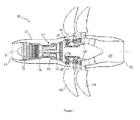
- a twin-spooled, contra-rotating propeller gas turbine engine is generally indicated at 10 and has a principal and rotational axis 9.
- the engine 10 comprises a core engine 11 having, in axial flow series, an air intake 12, a low pressure compressor 14 (LPC), a high-pressure compressor 15 (HPC), combustion equipment 16, a high-pressure turbine 17 (HPT), low pressure turbine 18 (LPT), a free power turbine 19 (FPT) and a core exhaust nozzle 20.
- a nacelle 21 generally surrounds the core engine 11 and defines the intake 12 and nozzle 20 and a core exhaust duct 22.
- the engine 10 also comprises two contra-rotating propellers 23, 24 attached to and driven by the free power turbine 19, which comprises contra-rotating blade arrays 25, 26.
- the free turbine may be a single rotation turbine driving counter-rotating propellers by an epicyclic gearbox.
- the gas turbine engine 10 works in a conventional manner so that air entering the intake 12 is accelerated and compressed by the LPC 14 and directed into the HPC 15 where further compression takes place.
- the compressed air exhausted from the HPC 15 is directed into the combustion equipment 16 where it is mixed with fuel and the mixture combusted.
- the resultant hot combustion products then expand through, and thereby drive the high, low-pressure and free power turbines 17, 18, 19 before being exhausted through the nozzle 20 to provide some propulsive thrust.
- the high, low-pressure and free power turbines 17, 18, 19 respectively drive the high and low pressure compressors 15, 14 and the propellers 23, 24 by suitable interconnecting shafts.
- the propellers 23, 24 normally provide the majority of the propulsive thrust.
- the propellers 23, 24 are critical components that can cause great damage to the aircraft or people or facilities in the ground if they become released.
- Aero propellers whether single rotor or contra-rotating, or whether in a pusher configuration as shown in Figure 1 or a puller configuration, usually have a means of varying the blade pitch via a pitch control mechanism (PCM), to optimise efficiency of thrust delivery and to reduce noise throughout the flight envelope, to provide reverse thrust, and to be able to feather the blades to control drag and rotor speed in some powerplant failure cases.
- PCM pitch control mechanism
- There are a number of established ways of configuring a PCM but all feature a source of power, prime mover, mechanism from prime mover to blade, and a failsafe system.
- the power source can be in the static or rotating field, although it is more common for it to be in the static field to avoid static to rotating control communication issues and for easier line replacement of faulty components. However, where the power source is in the static field, a means of transferring the power to the rotating field(s) is required.
- An aim of the present invention to provide a mounting system for mounting a propeller blade to a rotor body which has a back-up retention capability in order to provide increased protection against inadvertent blade release.
- the present invention is at least partly based on a realisation that pitch control mechanisms can conveniently be adapted to provide such capability.
- a first aspect of the present invention provides a mounting system for mounting a blade to a rotor body, the system having:
- the pitch control mechanism which has a primary function of varying the blade pitch, can also provide a back up load path for blade centrifugal loads on failure of the primary bearing formation. This is a significant safety advantage. Further, there is usually little weight penalty involved in adopting the back-up retention formation.
- the mounting system may have any one or, to the extent that they are compatible, any combination of the following optional features.
- the blade is a propeller blade, but may be e.g. a fan blade.
- the rotor body may have a radially outer hub and a radially inner hub, the primary bearing formation transmitting blade centrifugal loads to the rotor body at the outer hub, and the secondary bearing formation transmitting pitch change mechanism centrifugal loads to the rotor body at the inner hub.
- the inner and outer hubs may be separated by an annulus which, in use, carries engine exhaust gases.
- the torque-transmitting formation can be located between a radially outer end of the pitch change rod and the base of the blade. Another option, however, is for the torque-transmitting formation to be located between the radially inner end of the pitch change rod and the anchor.
- the torque-transmitting formation can be provided by male and female coupling members.
- the coupling members may have respective interengaging sets of splines to transmit the torque between the members.
- the blade is separable from the rotor body at the torque-transmitting formation.
- the back-up retention formation can allow up to 5 mm, and preferably up to 3 or 2 mm, of outward radial movement of the blade relative to the anchor before engaging to divert blade centrifugal loads through the secondary bearing formation to the rotor body.
- the back-up retention formation can be adjacent to the torque-transmitting formation.
- the back-up retention formation may be provided by abutment surfaces, which in normal operation are spaced apart, but engage together on outward radial movement of the blade relative to the anchor to divert blade centrifugal loads across an interface formed between the abutment surfaces.
- the abutment surfaces can be provided by lugs, screw threads, pegs and hook slots etc.
- the pitch control mechanism may further include a crank (such as bell crank) for rotating the anchor, the crank being operable by a unison ring.
- a crank such as bell crank
- a second aspect of the present invention provides a propeller or fan assembly having:
- a third aspect of the present invention provides an engine arrangement having:
- the power plant can be a gas turbine engine.
- the engine arrangement may have contra-rotating propeller assemblies, each according to the second aspect.
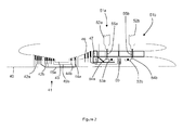
- FIG. 2 A schematic longitudinal cross-section through a pusher style, contra-rotating propeller, turboprop engine having a centre line 40 is shown in Figure 2 .
- the engine has a generator section 41 comprising in flow series low pressure 42a and high pressure 42b compressor subsections, a combustor subsection 43, and high pressure 44b and low pressure 44a turbine subsections.
- Generator drive shafts 45a, 45b connect the respective compressor and turbine subsections. Downstream of the generator section is a free power turbine 46 which drives a rearwardly extending power drive shaft 47.
- the distal end of the power drive shaft 47 drives an epicyclic gear assembly 50 which is coaxial with the power drive shaft.
- the gear assembly drives a first propeller assembly 51 a on the upstream side of the assembly, and a contra-rotating second propeller assembly 51 b on the downstream side of the assembly.
- Each propeller assembly has a row of propeller blades 52a, 52b, with each blade being rotatable about its longitudinal axis to vary the blade pitch.
- the pitch variation for each propeller assembly is achieved by a respective main hydraulic actuator 53a, 53b which moves a corresponding unison ring 54a, 54b in the axial direction of the engine.
- the axial movement of the unison rings rotates the blades via a pitch rod and bell crank arrangement 55a, 55b which extends from the base of each blade.
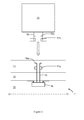
- FIG 3 shows schematically more detail of a mounting system for mounting a propeller blade 70 to a rotor body 71.
- the system is suitable for use in engines of the type shown in Figures 1 and 2 , but has wider applicability e.g. to engines with single propeller assemblies and also to puller style engines.
- the rotor body has a centre line O-O, and comprises a radially inner part 72 and a radially outer part 73 with a flow annulus 74 for hot exhaust gases from the engine therebetween.
- a pitch control rod 75 of a PCM extends across the flow annulus.
- the radially inner end of the rod terminates in an anchor 76, while the radially outer end of the rod terminates in a male coupling member 77a of a torque-transmitting formation.
- the blade has a neck 78 at its base, the neck carrying the female coupling member 77b of the torque-transmitting formation.
- Each coupling member 77a, 77b has a respective set of splines.
- the sets of splines are inter-engaged. Torque can then be transmitted across the coupling members so that rotation of the anchor 76 and the pitch control rod 75 about the longitudinal axis of the rod leads to pitch variation of the blade.
- the PCM may have, for example, a bell crank that rotates the anchor. The bell cranks of the PCMs of all the propellers in a given propeller assembly can then be operated by a unison ring.
- the anchor may be a pitch ram cylinder or similar component.
- the radially outer end of the pitch control rod 75 also carries a lugged structure 79a in which at least three, but preferably four or more equally spaced lugs are arranged around the circumference of the end of the rod.
- a corresponding lugged structure 79b is formed above the female coupling member 77b on the blade neck 78.
- the two lugged structures can thus pass by each other when the blade is moved in the radial direction of the arrow of Figure 3 .
- the sets of splines of the coupling member 77a, 77b inter-engage as they also pass through each other.
- the blade continues to be moved until the sets of splines are beyond each other and out of engagement, and the blade can be rotated so that the lugs of the two lugged structures overlap.
- the blade is then moved in the reverse direction so that the sets of splines re-engage.
- the overlapping lugged structures are not allowed to contact, but rather are held at a spacing of about 2-3 mm from each other.
- the overlapping lugged structures 79a, 79b provide a back-up retention formation for the blade.
- the operation of the back-up retention formation is described in more detail below.
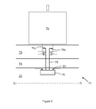
- a primary bearing formation is formed in order to transmit blade centrifugal loads to the rotor body 71, as shown in Figure 4 .
- the primary bearing formation comprises inner 80a and outer 80b bearings which are located at suitable structures carried by the blade neck 78.
- the inner bearing can be a ball bearing and the outer bearing can be a taper roller or a ball bearing.
- the bearings 80a, 80b transmit the blade centrifugal loads to a hub (not shown) of the outer part 73 of the rotor body.
- PCM centrifugal loads are transmitted to the rotor body 71 by a secondary bearing formation 81 which is formed around the anchor 76.
- This bearing formation transmits the PCM centrifugal loads to another hub (not shown) of the inner part 72 of the rotor body, and can be, for example, a barrel roller bearing.
- the back-up retention formation provides a back-up load path for the blade centrifugal loads in the event of partial or total failure of the primary bearing formation.
- failure can be, for example, in the inner 80a and outer 80b bearings or in the hub of the outer part 73 of the rotor body 71.
- the primary and secondary bearing formations maintain the radial spacing between the anchor 76 and the blade 70.
- the blade moves outwardly (indicated by the arrow) until the overlapping lugged structures 79a, 79b of the back-up retention formation engage each other, i.e. abutment surfaces provided by the lugs, which surfaces are normally spaced apart, contact each other so that blade centrifugal loads can divert across the interface formed between the abutment surfaces.
- the blade centrifugal load is then transmitted along the pitch rod 75, through the anchor 76 to the secondary bearing formation, and thence to the hub of the inner part 72 of the rotor body 71.
- the blade may not be able to pitch effectively due to the increased load through the secondary bearing formation. However, as long as the inner hub holds, the blade can be safely retained. Providing the inner hub with a wetted (i.e. oiled) failure case radial contact surface, may increase the ability of the blade to pitch even after bearing failure in the secondary bearing formation.
- the mounting system allows effective blade retention in the event of blade primary retention failure, the blade centrifugal loads being carried by an alternative path to the PCM anchor 76.
- the PCM can be adapted to perform back-up retention with relatively few alterations, and therefore does not increase significantly component costs or weight.
Landscapes
- Engineering & Computer Science (AREA)
- Mechanical Engineering (AREA)
- General Engineering & Computer Science (AREA)
- Chemical & Material Sciences (AREA)
- Combustion & Propulsion (AREA)
- Aviation & Aerospace Engineering (AREA)
- Structures Of Non-Positive Displacement Pumps (AREA)
- Turbine Rotor Nozzle Sealing (AREA)
- Wind Motors (AREA)
Applications Claiming Priority (1)
| Application Number | Priority Date | Filing Date | Title |
|---|---|---|---|
| GB1109227.7A GB2491811B (en) | 2011-06-14 | 2011-06-14 | Mounting system |
Publications (3)
| Publication Number | Publication Date |
|---|---|
| EP2535518A2 true EP2535518A2 (de) | 2012-12-19 |
| EP2535518A3 EP2535518A3 (de) | 2014-11-12 |
| EP2535518B1 EP2535518B1 (de) | 2018-02-28 |
Family
ID=44310737
Family Applications (1)
| Application Number | Title | Priority Date | Filing Date |
|---|---|---|---|
| EP12169971.4A Active EP2535518B1 (de) | 2011-06-14 | 2012-05-30 | Montagesystem einer Schaufel |
Country Status (5)
| Country | Link |
|---|---|
| US (1) | US8985946B2 (de) |
| EP (1) | EP2535518B1 (de) |
| JP (1) | JP6121108B2 (de) |
| CA (1) | CA2778584C (de) |
| GB (1) | GB2491811B (de) |
Cited By (1)
| Publication number | Priority date | Publication date | Assignee | Title |
|---|---|---|---|---|
| GB2551631A (en) * | 2016-04-28 | 2017-12-27 | Airbus Operations Sas | Propeller for an aircraft turbo engine, including safety means for controlling blade angle of attack |
Families Citing this family (6)
| Publication number | Priority date | Publication date | Assignee | Title |
|---|---|---|---|---|
| GB201211133D0 (en) * | 2012-06-22 | 2012-08-08 | Rolls Royce Plc | A catcher ring arrangement |
| US10077674B2 (en) * | 2015-06-23 | 2018-09-18 | General Electric Company | Trunnion retention for a turbine engine |
| PL226824B1 (pl) * | 2015-09-07 | 2017-09-29 | Gen Electric | Układ isposób regulacji skoku smigła |
| US10787931B2 (en) * | 2017-05-25 | 2020-09-29 | General Electric Company | Method and structure of interdigitated turbine engine thermal management |
| US11428160B2 (en) | 2020-12-31 | 2022-08-30 | General Electric Company | Gas turbine engine with interdigitated turbine and gear assembly |
| US11834995B2 (en) | 2022-03-29 | 2023-12-05 | General Electric Company | Air-to-air heat exchanger potential in gas turbine engines |
Family Cites Families (11)
| Publication number | Priority date | Publication date | Assignee | Title |
|---|---|---|---|---|
| GB546621A (en) * | 1940-12-19 | 1942-07-22 | Leonard Gaskell Fairhurst | Improvements in or relating to variable-pitch airscrews |
| GB825303A (en) * | 1957-04-15 | 1959-12-16 | Rotol Ltd | Improvements in or relating to variable pitch propellers |
| US3988889A (en) * | 1974-02-25 | 1976-11-02 | General Electric Company | Cowling arrangement for a turbofan engine |
| US4171183A (en) * | 1976-09-24 | 1979-10-16 | United Technologies Corporation | Multi-bladed, high speed prop-fan |
| US4863352A (en) * | 1984-11-02 | 1989-09-05 | General Electric Company | Blade carrying means |
| US5263898A (en) * | 1988-12-14 | 1993-11-23 | General Electric Company | Propeller blade retention system |
| GB9616170D0 (en) | 1996-08-01 | 1996-09-11 | Timken The Company | Bearing assembly |
| JP3633219B2 (ja) * | 1997-07-04 | 2005-03-30 | 日本精工株式会社 | スプライン結合構造 |
| FR2942454B1 (fr) * | 2009-02-23 | 2012-09-14 | Airbus France | Dispositif de retenue d'aube pour helice de turbomachine. |
| FR2943312B1 (fr) | 2009-03-23 | 2011-05-27 | Snecma | Helice non carenee a pales a calage variable pour une turbomachine |
| FR2943985B1 (fr) * | 2009-04-07 | 2011-05-13 | Airbus France | Helice pour turbomachine d'aeronef comprenant un anneau de retention d'aubes monte autour du moyeu. |
-
2011
- 2011-06-14 GB GB1109227.7A patent/GB2491811B/en not_active Expired - Fee Related
-
2012
- 2012-05-30 EP EP12169971.4A patent/EP2535518B1/de active Active
- 2012-05-30 US US13/483,461 patent/US8985946B2/en active Active
- 2012-06-01 CA CA2778584A patent/CA2778584C/en active Active
- 2012-06-14 JP JP2012134510A patent/JP6121108B2/ja not_active Expired - Fee Related
Non-Patent Citations (1)
| Title |
|---|
| None |
Cited By (2)
| Publication number | Priority date | Publication date | Assignee | Title |
|---|---|---|---|---|
| GB2551631A (en) * | 2016-04-28 | 2017-12-27 | Airbus Operations Sas | Propeller for an aircraft turbo engine, including safety means for controlling blade angle of attack |
| GB2551631B (en) * | 2016-04-28 | 2021-03-03 | Airbus Operations Sas | Propeller for an aircraft turbo engine, including safety means for controlling blade angle of attack |
Also Published As
| Publication number | Publication date |
|---|---|
| GB2491811B (en) | 2013-10-09 |
| EP2535518B1 (de) | 2018-02-28 |
| GB2491811A (en) | 2012-12-19 |
| US20120321470A1 (en) | 2012-12-20 |
| GB201109227D0 (en) | 2011-07-13 |
| JP6121108B2 (ja) | 2017-04-26 |
| EP2535518A3 (de) | 2014-11-12 |
| CA2778584C (en) | 2019-01-15 |
| US8985946B2 (en) | 2015-03-24 |
| JP2013001394A (ja) | 2013-01-07 |
| CA2778584A1 (en) | 2012-12-14 |
Similar Documents
| Publication | Publication Date | Title |
|---|---|---|
| EP2535518B1 (de) | Montagesystem einer Schaufel | |
| US9033654B2 (en) | Variable geometry vane system for gas turbine engines | |
| EP2452879B1 (de) | Antriebssystem für ein Luftfahrzeug | |
| US12092040B2 (en) | Selective power distribution for an aircraft propulsion system | |
| EP4282763B1 (de) | Selektive leistungsverteilung für ein flugzeugantriebssystem | |
| EP4325031A1 (de) | Selektive leistungsverteilung für ein flugzeugantriebssystem | |
| US12043405B2 (en) | Selective power distribution for an aircraft propulsion system | |
| CN110645095A (zh) | 气体涡轮机 | |
| US11506067B2 (en) | Gas turbine engine with clutch assembly | |
| US12492663B2 (en) | Aircraft propulsion system geartrain | |
| EP3569507B1 (de) | Flugzeugantriebssystem | |
| US12071900B2 (en) | Aircraft propulsion system geartrain | |
| EP4306424A1 (de) | Flugzeugantriebssystem mit intermittierendem verbrennungsmotor/-vorrichtungen | |
| EP4365429A1 (de) | Getriebe für ein flugzeugantriebssystem | |
| US12378000B2 (en) | Aircraft propulsion system geartrain | |
| US20240110522A1 (en) | Shaft coupling for a gas turbine engine | |
| EP4345007B1 (de) | Selektive leistungsverteilung für ein flugzeugantriebssystem | |
| EP4345007A2 (de) | Selektive leistungsverteilung für ein flugzeugantriebssystem |
Legal Events
| Date | Code | Title | Description |
|---|---|---|---|
| PUAI | Public reference made under article 153(3) epc to a published international application that has entered the european phase |
Free format text: ORIGINAL CODE: 0009012 |
|
| AK | Designated contracting states |
Kind code of ref document: A2 Designated state(s): AL AT BE BG CH CY CZ DE DK EE ES FI FR GB GR HR HU IE IS IT LI LT LU LV MC MK MT NL NO PL PT RO RS SE SI SK SM TR |
|
| AX | Request for extension of the european patent |
Extension state: BA ME |
|
| PUAL | Search report despatched |
Free format text: ORIGINAL CODE: 0009013 |
|
| AK | Designated contracting states |
Kind code of ref document: A3 Designated state(s): AL AT BE BG CH CY CZ DE DK EE ES FI FR GB GR HR HU IE IS IT LI LT LU LV MC MK MT NL NO PL PT RO RS SE SI SK SM TR |
|
| AX | Request for extension of the european patent |
Extension state: BA ME |
|
| RIC1 | Information provided on ipc code assigned before grant |
Ipc: B64C 11/06 20060101ALI20141003BHEP Ipc: F01D 7/00 20060101ALI20141003BHEP Ipc: F01D 5/30 20060101AFI20141003BHEP Ipc: F02K 3/072 20060101ALI20141003BHEP |
|
| 17P | Request for examination filed |
Effective date: 20150512 |
|
| RBV | Designated contracting states (corrected) |
Designated state(s): AL AT BE BG CH CY CZ DE DK EE ES FI FR GB GR HR HU IE IS IT LI LT LU LV MC MK MT NL NO PL PT RO RS SE SI SK SM TR |
|
| RAP1 | Party data changed (applicant data changed or rights of an application transferred) |
Owner name: ROLLS-ROYCE PLC |
|
| REG | Reference to a national code |
Ref country code: DE Ref legal event code: R079 Ref document number: 602012043282 Country of ref document: DE Free format text: PREVIOUS MAIN CLASS: F01D0005300000 Ipc: F02C0006200000 |
|
| RIC1 | Information provided on ipc code assigned before grant |
Ipc: B64C 11/30 20060101ALI20170831BHEP Ipc: F01D 7/00 20060101ALI20170831BHEP Ipc: F02C 6/20 20060101AFI20170831BHEP Ipc: F01D 5/30 20060101ALI20170831BHEP Ipc: F02K 3/072 20060101ALI20170831BHEP |
|
| GRAP | Despatch of communication of intention to grant a patent |
Free format text: ORIGINAL CODE: EPIDOSNIGR1 |
|
| STAA | Information on the status of an ep patent application or granted ep patent |
Free format text: STATUS: GRANT OF PATENT IS INTENDED |
|
| INTG | Intention to grant announced |
Effective date: 20171016 |
|
| GRAS | Grant fee paid |
Free format text: ORIGINAL CODE: EPIDOSNIGR3 |
|
| GRAA | (expected) grant |
Free format text: ORIGINAL CODE: 0009210 |
|
| STAA | Information on the status of an ep patent application or granted ep patent |
Free format text: STATUS: THE PATENT HAS BEEN GRANTED |
|
| AK | Designated contracting states |
Kind code of ref document: B1 Designated state(s): AL AT BE BG CH CY CZ DE DK EE ES FI FR GB GR HR HU IE IS IT LI LT LU LV MC MK MT NL NO PL PT RO RS SE SI SK SM TR |
|
| REG | Reference to a national code |
Ref country code: GB Ref legal event code: FG4D Ref country code: CH Ref legal event code: EP |
|
| REG | Reference to a national code |
Ref country code: AT Ref legal event code: REF Ref document number: 974406 Country of ref document: AT Kind code of ref document: T Effective date: 20180315 |
|
| REG | Reference to a national code |
Ref country code: IE Ref legal event code: FG4D |
|
| REG | Reference to a national code |
Ref country code: DE Ref legal event code: R096 Ref document number: 602012043282 Country of ref document: DE |
|
| REG | Reference to a national code |
Ref country code: FR Ref legal event code: PLFP Year of fee payment: 7 |
|
| REG | Reference to a national code |
Ref country code: NL Ref legal event code: MP Effective date: 20180228 |
|
| REG | Reference to a national code |
Ref country code: LT Ref legal event code: MG4D |
|
| REG | Reference to a national code |
Ref country code: AT Ref legal event code: MK05 Ref document number: 974406 Country of ref document: AT Kind code of ref document: T Effective date: 20180228 |
|
| PG25 | Lapsed in a contracting state [announced via postgrant information from national office to epo] |
Ref country code: NO Free format text: LAPSE BECAUSE OF FAILURE TO SUBMIT A TRANSLATION OF THE DESCRIPTION OR TO PAY THE FEE WITHIN THE PRESCRIBED TIME-LIMIT Effective date: 20180528 Ref country code: FI Free format text: LAPSE BECAUSE OF FAILURE TO SUBMIT A TRANSLATION OF THE DESCRIPTION OR TO PAY THE FEE WITHIN THE PRESCRIBED TIME-LIMIT Effective date: 20180228 Ref country code: NL Free format text: LAPSE BECAUSE OF FAILURE TO SUBMIT A TRANSLATION OF THE DESCRIPTION OR TO PAY THE FEE WITHIN THE PRESCRIBED TIME-LIMIT Effective date: 20180228 Ref country code: HR Free format text: LAPSE BECAUSE OF FAILURE TO SUBMIT A TRANSLATION OF THE DESCRIPTION OR TO PAY THE FEE WITHIN THE PRESCRIBED TIME-LIMIT Effective date: 20180228 Ref country code: LT Free format text: LAPSE BECAUSE OF FAILURE TO SUBMIT A TRANSLATION OF THE DESCRIPTION OR TO PAY THE FEE WITHIN THE PRESCRIBED TIME-LIMIT Effective date: 20180228 Ref country code: ES Free format text: LAPSE BECAUSE OF FAILURE TO SUBMIT A TRANSLATION OF THE DESCRIPTION OR TO PAY THE FEE WITHIN THE PRESCRIBED TIME-LIMIT Effective date: 20180228 Ref country code: CY Free format text: LAPSE BECAUSE OF FAILURE TO SUBMIT A TRANSLATION OF THE DESCRIPTION OR TO PAY THE FEE WITHIN THE PRESCRIBED TIME-LIMIT Effective date: 20180228 |
|
| PGFP | Annual fee paid to national office [announced via postgrant information from national office to epo] |
Ref country code: ES Payment date: 20180601 Year of fee payment: 7 |
|
| PG25 | Lapsed in a contracting state [announced via postgrant information from national office to epo] |
Ref country code: BG Free format text: LAPSE BECAUSE OF FAILURE TO SUBMIT A TRANSLATION OF THE DESCRIPTION OR TO PAY THE FEE WITHIN THE PRESCRIBED TIME-LIMIT Effective date: 20180528 Ref country code: GR Free format text: LAPSE BECAUSE OF FAILURE TO SUBMIT A TRANSLATION OF THE DESCRIPTION OR TO PAY THE FEE WITHIN THE PRESCRIBED TIME-LIMIT Effective date: 20180529 Ref country code: SE Free format text: LAPSE BECAUSE OF FAILURE TO SUBMIT A TRANSLATION OF THE DESCRIPTION OR TO PAY THE FEE WITHIN THE PRESCRIBED TIME-LIMIT Effective date: 20180228 Ref country code: LV Free format text: LAPSE BECAUSE OF FAILURE TO SUBMIT A TRANSLATION OF THE DESCRIPTION OR TO PAY THE FEE WITHIN THE PRESCRIBED TIME-LIMIT Effective date: 20180228 Ref country code: AT Free format text: LAPSE BECAUSE OF FAILURE TO SUBMIT A TRANSLATION OF THE DESCRIPTION OR TO PAY THE FEE WITHIN THE PRESCRIBED TIME-LIMIT Effective date: 20180228 Ref country code: RS Free format text: LAPSE BECAUSE OF FAILURE TO SUBMIT A TRANSLATION OF THE DESCRIPTION OR TO PAY THE FEE WITHIN THE PRESCRIBED TIME-LIMIT Effective date: 20180228 |
|
| PG25 | Lapsed in a contracting state [announced via postgrant information from national office to epo] |
Ref country code: EE Free format text: LAPSE BECAUSE OF FAILURE TO SUBMIT A TRANSLATION OF THE DESCRIPTION OR TO PAY THE FEE WITHIN THE PRESCRIBED TIME-LIMIT Effective date: 20180228 Ref country code: IT Free format text: LAPSE BECAUSE OF FAILURE TO SUBMIT A TRANSLATION OF THE DESCRIPTION OR TO PAY THE FEE WITHIN THE PRESCRIBED TIME-LIMIT Effective date: 20180228 Ref country code: AL Free format text: LAPSE BECAUSE OF FAILURE TO SUBMIT A TRANSLATION OF THE DESCRIPTION OR TO PAY THE FEE WITHIN THE PRESCRIBED TIME-LIMIT Effective date: 20180228 Ref country code: RO Free format text: LAPSE BECAUSE OF FAILURE TO SUBMIT A TRANSLATION OF THE DESCRIPTION OR TO PAY THE FEE WITHIN THE PRESCRIBED TIME-LIMIT Effective date: 20180228 Ref country code: PL Free format text: LAPSE BECAUSE OF FAILURE TO SUBMIT A TRANSLATION OF THE DESCRIPTION OR TO PAY THE FEE WITHIN THE PRESCRIBED TIME-LIMIT Effective date: 20180228 |
|
| REG | Reference to a national code |
Ref country code: DE Ref legal event code: R097 Ref document number: 602012043282 Country of ref document: DE |
|
| PG25 | Lapsed in a contracting state [announced via postgrant information from national office to epo] |
Ref country code: CZ Free format text: LAPSE BECAUSE OF FAILURE TO SUBMIT A TRANSLATION OF THE DESCRIPTION OR TO PAY THE FEE WITHIN THE PRESCRIBED TIME-LIMIT Effective date: 20180228 Ref country code: SK Free format text: LAPSE BECAUSE OF FAILURE TO SUBMIT A TRANSLATION OF THE DESCRIPTION OR TO PAY THE FEE WITHIN THE PRESCRIBED TIME-LIMIT Effective date: 20180228 Ref country code: DK Free format text: LAPSE BECAUSE OF FAILURE TO SUBMIT A TRANSLATION OF THE DESCRIPTION OR TO PAY THE FEE WITHIN THE PRESCRIBED TIME-LIMIT Effective date: 20180228 Ref country code: SM Free format text: LAPSE BECAUSE OF FAILURE TO SUBMIT A TRANSLATION OF THE DESCRIPTION OR TO PAY THE FEE WITHIN THE PRESCRIBED TIME-LIMIT Effective date: 20180228 |
|
| REG | Reference to a national code |
Ref country code: CH Ref legal event code: PL |
|
| PLBE | No opposition filed within time limit |
Free format text: ORIGINAL CODE: 0009261 |
|
| STAA | Information on the status of an ep patent application or granted ep patent |
Free format text: STATUS: NO OPPOSITION FILED WITHIN TIME LIMIT |
|
| REG | Reference to a national code |
Ref country code: BE Ref legal event code: MM Effective date: 20180531 |
|
| PG25 | Lapsed in a contracting state [announced via postgrant information from national office to epo] |
Ref country code: MC Free format text: LAPSE BECAUSE OF FAILURE TO SUBMIT A TRANSLATION OF THE DESCRIPTION OR TO PAY THE FEE WITHIN THE PRESCRIBED TIME-LIMIT Effective date: 20180228 |
|
| 26N | No opposition filed |
Effective date: 20181129 |
|
| REG | Reference to a national code |
Ref country code: IE Ref legal event code: MM4A |
|
| PG25 | Lapsed in a contracting state [announced via postgrant information from national office to epo] |
Ref country code: CH Free format text: LAPSE BECAUSE OF NON-PAYMENT OF DUE FEES Effective date: 20180531 Ref country code: SI Free format text: LAPSE BECAUSE OF FAILURE TO SUBMIT A TRANSLATION OF THE DESCRIPTION OR TO PAY THE FEE WITHIN THE PRESCRIBED TIME-LIMIT Effective date: 20180228 Ref country code: LI Free format text: LAPSE BECAUSE OF NON-PAYMENT OF DUE FEES Effective date: 20180531 |
|
| PG25 | Lapsed in a contracting state [announced via postgrant information from national office to epo] |
Ref country code: LU Free format text: LAPSE BECAUSE OF NON-PAYMENT OF DUE FEES Effective date: 20180530 |
|
| PG25 | Lapsed in a contracting state [announced via postgrant information from national office to epo] |
Ref country code: IE Free format text: LAPSE BECAUSE OF NON-PAYMENT OF DUE FEES Effective date: 20180530 |
|
| PG25 | Lapsed in a contracting state [announced via postgrant information from national office to epo] |
Ref country code: BE Free format text: LAPSE BECAUSE OF NON-PAYMENT OF DUE FEES Effective date: 20180531 |
|
| PGFP | Annual fee paid to national office [announced via postgrant information from national office to epo] |
Ref country code: DE Payment date: 20190530 Year of fee payment: 8 |
|
| PG25 | Lapsed in a contracting state [announced via postgrant information from national office to epo] |
Ref country code: MT Free format text: LAPSE BECAUSE OF NON-PAYMENT OF DUE FEES Effective date: 20180530 |
|
| PG25 | Lapsed in a contracting state [announced via postgrant information from national office to epo] |
Ref country code: TR Free format text: LAPSE BECAUSE OF FAILURE TO SUBMIT A TRANSLATION OF THE DESCRIPTION OR TO PAY THE FEE WITHIN THE PRESCRIBED TIME-LIMIT Effective date: 20180228 |
|
| PG25 | Lapsed in a contracting state [announced via postgrant information from national office to epo] |
Ref country code: HU Free format text: LAPSE BECAUSE OF FAILURE TO SUBMIT A TRANSLATION OF THE DESCRIPTION OR TO PAY THE FEE WITHIN THE PRESCRIBED TIME-LIMIT; INVALID AB INITIO Effective date: 20120530 Ref country code: PT Free format text: LAPSE BECAUSE OF FAILURE TO SUBMIT A TRANSLATION OF THE DESCRIPTION OR TO PAY THE FEE WITHIN THE PRESCRIBED TIME-LIMIT Effective date: 20180228 |
|
| PG25 | Lapsed in a contracting state [announced via postgrant information from national office to epo] |
Ref country code: MK Free format text: LAPSE BECAUSE OF NON-PAYMENT OF DUE FEES Effective date: 20180228 |
|
| PG25 | Lapsed in a contracting state [announced via postgrant information from national office to epo] |
Ref country code: IS Free format text: LAPSE BECAUSE OF FAILURE TO SUBMIT A TRANSLATION OF THE DESCRIPTION OR TO PAY THE FEE WITHIN THE PRESCRIBED TIME-LIMIT Effective date: 20180628 |
|
| REG | Reference to a national code |
Ref country code: DE Ref legal event code: R119 Ref document number: 602012043282 Country of ref document: DE |
|
| PG25 | Lapsed in a contracting state [announced via postgrant information from national office to epo] |
Ref country code: DE Free format text: LAPSE BECAUSE OF NON-PAYMENT OF DUE FEES Effective date: 20201201 |
|
| P01 | Opt-out of the competence of the unified patent court (upc) registered |
Effective date: 20230528 |
|
| PGFP | Annual fee paid to national office [announced via postgrant information from national office to epo] |
Ref country code: GB Payment date: 20230523 Year of fee payment: 12 |
|
| GBPC | Gb: european patent ceased through non-payment of renewal fee |
Effective date: 20240530 |
|
| PG25 | Lapsed in a contracting state [announced via postgrant information from national office to epo] |
Ref country code: GB Free format text: LAPSE BECAUSE OF NON-PAYMENT OF DUE FEES Effective date: 20240530 |
|
| PGFP | Annual fee paid to national office [announced via postgrant information from national office to epo] |
Ref country code: FR Payment date: 20250526 Year of fee payment: 14 |