EP2535259A1 - Array of floating photovoltaic elements - Google Patents
Array of floating photovoltaic elements Download PDFInfo
- Publication number
- EP2535259A1 EP2535259A1 EP12171838A EP12171838A EP2535259A1 EP 2535259 A1 EP2535259 A1 EP 2535259A1 EP 12171838 A EP12171838 A EP 12171838A EP 12171838 A EP12171838 A EP 12171838A EP 2535259 A1 EP2535259 A1 EP 2535259A1
- Authority
- EP
- European Patent Office
- Prior art keywords
- photovoltaic
- cable
- floating
- elements
- buoy
- Prior art date
- Legal status (The legal status is an assumption and is not a legal conclusion. Google has not performed a legal analysis and makes no representation as to the accuracy of the status listed.)
- Granted
Links
- 238000000034 method Methods 0.000 claims abstract description 7
- XLYOFNOQVPJJNP-UHFFFAOYSA-N water Substances O XLYOFNOQVPJJNP-UHFFFAOYSA-N 0.000 claims description 69
- 238000005188 flotation Methods 0.000 claims description 5
- 230000015572 biosynthetic process Effects 0.000 claims description 4
- 239000007787 solid Substances 0.000 claims description 3
- 238000009826 distribution Methods 0.000 claims description 2
- 238000009434 installation Methods 0.000 description 13
- 230000008859 change Effects 0.000 description 7
- 230000008901 benefit Effects 0.000 description 6
- 239000000463 material Substances 0.000 description 6
- 210000004027 cell Anatomy 0.000 description 4
- 238000012937 correction Methods 0.000 description 4
- 230000006978 adaptation Effects 0.000 description 3
- 238000001816 cooling Methods 0.000 description 3
- 238000006073 displacement reaction Methods 0.000 description 3
- 230000006870 function Effects 0.000 description 3
- 230000007246 mechanism Effects 0.000 description 3
- 238000003032 molecular docking Methods 0.000 description 3
- 210000000056 organ Anatomy 0.000 description 3
- 230000000903 blocking effect Effects 0.000 description 2
- 239000011159 matrix material Substances 0.000 description 2
- 230000004048 modification Effects 0.000 description 2
- 238000012986 modification Methods 0.000 description 2
- 230000000284 resting effect Effects 0.000 description 2
- 230000006641 stabilisation Effects 0.000 description 2
- 238000011105 stabilization Methods 0.000 description 2
- 238000010521 absorption reaction Methods 0.000 description 1
- 230000009471 action Effects 0.000 description 1
- 238000003491 array Methods 0.000 description 1
- 230000004888 barrier function Effects 0.000 description 1
- 210000003850 cellular structure Anatomy 0.000 description 1
- 238000010276 construction Methods 0.000 description 1
- 230000008602 contraction Effects 0.000 description 1
- 230000007423 decrease Effects 0.000 description 1
- 230000000694 effects Effects 0.000 description 1
- 230000002209 hydrophobic effect Effects 0.000 description 1
- 238000005286 illumination Methods 0.000 description 1
- 238000009776 industrial production Methods 0.000 description 1
- 230000001788 irregular Effects 0.000 description 1
- 238000002844 melting Methods 0.000 description 1
- 230000008018 melting Effects 0.000 description 1
- 239000002184 metal Substances 0.000 description 1
- 238000012544 monitoring process Methods 0.000 description 1
- 210000004417 patella Anatomy 0.000 description 1
- 230000008569 process Effects 0.000 description 1
- 230000009467 reduction Effects 0.000 description 1
- 230000004044 response Effects 0.000 description 1
- 230000001932 seasonal effect Effects 0.000 description 1
- 229910001220 stainless steel Inorganic materials 0.000 description 1
- 239000010935 stainless steel Substances 0.000 description 1
- 238000004381 surface treatment Methods 0.000 description 1
- 230000001131 transforming effect Effects 0.000 description 1
- 238000013519 translation Methods 0.000 description 1
- 230000001960 triggered effect Effects 0.000 description 1
Images


Classifications
-
- B—PERFORMING OPERATIONS; TRANSPORTING
- B63—SHIPS OR OTHER WATERBORNE VESSELS; RELATED EQUIPMENT
- B63B—SHIPS OR OTHER WATERBORNE VESSELS; EQUIPMENT FOR SHIPPING
- B63B35/00—Vessels or similar floating structures specially adapted for specific purposes and not otherwise provided for
- B63B35/44—Floating buildings, stores, drilling platforms, or workshops, e.g. carrying water-oil separating devices
-
- F—MECHANICAL ENGINEERING; LIGHTING; HEATING; WEAPONS; BLASTING
- F24—HEATING; RANGES; VENTILATING
- F24S—SOLAR HEAT COLLECTORS; SOLAR HEAT SYSTEMS
- F24S20/00—Solar heat collectors specially adapted for particular uses or environments
- F24S20/70—Waterborne solar heat collector modules
-
- F—MECHANICAL ENGINEERING; LIGHTING; HEATING; WEAPONS; BLASTING
- F24—HEATING; RANGES; VENTILATING
- F24S—SOLAR HEAT COLLECTORS; SOLAR HEAT SYSTEMS
- F24S30/00—Arrangements for moving or orienting solar heat collector modules
- F24S30/40—Arrangements for moving or orienting solar heat collector modules for rotary movement
- F24S30/42—Arrangements for moving or orienting solar heat collector modules for rotary movement with only one rotation axis
- F24S30/425—Horizontal axis
-
- H—ELECTRICITY
- H02—GENERATION; CONVERSION OR DISTRIBUTION OF ELECTRIC POWER
- H02S—GENERATION OF ELECTRIC POWER BY CONVERSION OF INFRARED RADIATION, VISIBLE LIGHT OR ULTRAVIOLET LIGHT, e.g. USING PHOTOVOLTAIC [PV] MODULES
- H02S20/00—Supporting structures for PV modules
-
- B—PERFORMING OPERATIONS; TRANSPORTING
- B63—SHIPS OR OTHER WATERBORNE VESSELS; RELATED EQUIPMENT
- B63B—SHIPS OR OTHER WATERBORNE VESSELS; EQUIPMENT FOR SHIPPING
- B63B35/00—Vessels or similar floating structures specially adapted for specific purposes and not otherwise provided for
- B63B35/44—Floating buildings, stores, drilling platforms, or workshops, e.g. carrying water-oil separating devices
- B63B2035/4433—Floating structures carrying electric power plants
- B63B2035/4453—Floating structures carrying electric power plants for converting solar energy into electric energy
-
- Y—GENERAL TAGGING OF NEW TECHNOLOGICAL DEVELOPMENTS; GENERAL TAGGING OF CROSS-SECTIONAL TECHNOLOGIES SPANNING OVER SEVERAL SECTIONS OF THE IPC; TECHNICAL SUBJECTS COVERED BY FORMER USPC CROSS-REFERENCE ART COLLECTIONS [XRACs] AND DIGESTS
- Y02—TECHNOLOGIES OR APPLICATIONS FOR MITIGATION OR ADAPTATION AGAINST CLIMATE CHANGE
- Y02E—REDUCTION OF GREENHOUSE GAS [GHG] EMISSIONS, RELATED TO ENERGY GENERATION, TRANSMISSION OR DISTRIBUTION
- Y02E10/00—Energy generation through renewable energy sources
- Y02E10/40—Solar thermal energy, e.g. solar towers
- Y02E10/47—Mountings or tracking
-
- Y—GENERAL TAGGING OF NEW TECHNOLOGICAL DEVELOPMENTS; GENERAL TAGGING OF CROSS-SECTIONAL TECHNOLOGIES SPANNING OVER SEVERAL SECTIONS OF THE IPC; TECHNICAL SUBJECTS COVERED BY FORMER USPC CROSS-REFERENCE ART COLLECTIONS [XRACs] AND DIGESTS
- Y02—TECHNOLOGIES OR APPLICATIONS FOR MITIGATION OR ADAPTATION AGAINST CLIMATE CHANGE
- Y02E—REDUCTION OF GREENHOUSE GAS [GHG] EMISSIONS, RELATED TO ENERGY GENERATION, TRANSMISSION OR DISTRIBUTION
- Y02E10/00—Energy generation through renewable energy sources
- Y02E10/50—Photovoltaic [PV] energy
Definitions
- the present invention relates to an array of floating photovoltaic elements arranged to be deployed in an aquatic environment.
- the document WO2008125154 describes a cellular structure comprising floating photovoltaic cells and interconnected by cables.
- the cables allow in particular to move the entire structure.
- the orientation of the photovoltaic panels is done by pivoting them relative to the buoys by means of an actuator on each cell. These actuators make the structure expensive and more susceptible to failure.
- the document EP2299499 describes a floating photovoltaic installation that can be anchored to the bottom of a barrier lake by means of cables of variable length depending on the water level.
- the photovoltaic cells are carried by buoys specific to each cell or common to a row of buoys. They are inclined at a fixed angle. The entire installation can turn to follow the sun. This installation presents the major disadvantage of not allowing to change the inclination of the panels.
- the document WO10144955 describes a set of floating waterproof rectangular modules each supporting a solar collector. Several modules are fixed in lines and each line can be electrically connected at the level of each module to one or two other lines to form a network. Each module includes its own solar collector orientation system. This solution is also a complex and expensive structure.
- Photovoltaic power plants must adapt to the constraints of nature (sunshine, snow cover, etc.) and the specific natural environment in which they are installed (mountain shadows, lake level variations, temperature, etc.)
- the document JP2003329963 describes a solar thermal installation comprising several reflectors whose orientation can be controlled by means of cables, in order to converge the solar rays into a single point.
- a complex cable system is necessary to simultaneously orient the different reflectors towards the same point.
- This system is not suitable for photovoltaic panels that are not reflective and should not all be turned in the direction of the sun.
- This support system is designed to be fixed on the ground. It is suitable only for a small number of reflectors whose weight is fully supported by the cables. It also has the disadvantage of requiring several cables and supporting a small number of reflectors.
- the US patent US4214572 discloses a solar energy collecting system comprising a plurality of solar energy collectors attached to a floating frame on the water and means for orienting the collectors according to the orientation of the sun.
- Each manifold is secured to the frame by a lower cable and an upper cable by means of a ball joint.
- a motorized device allows the length of the cable to be changed in response to a photoelectric sensor to change the inclination of the reflective surface from the horizontal and to reflect the maximum amount of solar energy on the absorption device.
- the frame is also rotated to keep the reflective surfaces facing the sun. In case of bad weather, the reflectors can be turned over, nozzles can be provided to clean the reflective surfaces.
- This system has the disadvantage of being bound to a rigid frame and requires for example expansion joints at appropriate intervals to compensate for expansions and contractions due to thermal variations. It can not adapt to changing water surfaces such as dam lakes.
- Another disadvantage of this system is related to the use of the upper cable for pivoting a multitude of collectors and for their support. This requires extreme cable tension especially if the number of collectors is large. It will be stretched at the ends of the network but curved towards the center. Pivoting collectors placed in the center of the network may not be done properly.
- Another disadvantage of this system is that the upper cable is placed higher than the collector. As a result, the network comprises a multitude of cables positioned above the collectors which may present a danger for example for birds.
- International demand WO200901225 relates to an energy collector system comprising a floating platform which comprises an outer annular structure, a flexible cover covering an upper end of the annular structure and thus defining an internal volume, a compressor for creating an overpressure of the internal volume, collector modules of solar energy, an upper structure placed above the cover supporting the modules, the platform being rotatable to follow the position of the sun.
- the system collector described in this application requires an extremely complex and expensive installation.
- the patent application US2006090789 describes a floating structure supporting rows of solar panels.
- the solar panels are pre-oriented with a fixed angle (preferably 20 °).
- This structure has the major disadvantage of not allowing the change of orientation of the panels as soon as they are installed.
- the patent application KR2009037020 relates to a light concentration device for an aquatic installation.
- a photovoltaic module is placed between buoys.
- a device for controlling the inclination of the photovoltaic module comprises tubes operating by means of an air suction or expiration process for raising or lowering the photovoltaic module.
- the installation is placed on the water and fixed by means of underwater anchors. This device has the disadvantage of requiring a complex and bulky pipe structure to orient the photovoltaic modules.
- An object of the present invention is to provide an array of floating photovoltaic elements free from the limitations of known networks.
- Another object of the present invention is to propose an alternative solution to existing photovoltaic floating element arrays.
- this object is achieved in particular by means of an array of floating photovoltaic elements according to claim 1, and a method of positioning a network of floating photovoltaic elements according to claim 14.
- This solution also has the advantage over the prior art of presenting a network of floating photovoltaic elements that adapts to even large variations in the level of lakes. This solution is thus particularly adapted to the dam lakes.
- the network of floating photovoltaic elements comprises at least one floating photovoltaic element and at least one cable for connecting the photovoltaic elements floating between them.
- Each floating photovoltaic element comprises a buoy and a photovoltaic surface fixed on the buoy. At least one photovoltaic surface can pivot about a horizontal axis, substantially parallel to the cable, the cable to adapt the pivot angle by changing its voltage.
- the expression “substantially parallel” means that the angle between the pivot axis of the photovoltaic surface and the cable may be between + 25 ° and -25 °, and preferably between + 10 ° and - 10 °.
- the array of floating photovoltaic elements advantageously comprises at least two adjacent photovoltaic elements connected by a cable portion of variable length depending on the vertical position of these two elements.
- the length of these cable portions is preferably adapted automatically to take into account the vertical distance between these two elements.
- the array of floating photovoltaic elements advantageously comprises at least one photovoltaic element connected to a point fixed at the edge of the water body by a portion of cable of variable length as a function of the vertical position of this element.
- the length of this portion of cable is preferably adapted automatically to take into account the variable vertical distance between the fixed point and the photovoltaic element.
- photovoltaic surface means an assembly comprising one or more photovoltaic panels capable of transforming solar energy into electrical energy.
- Commercially available photovoltaic panels can be used as photovoltaic panels.
- the different photovoltaic panels of a photovoltaic surface can be arranged sawtooth or horizontally or in any other way on a support.
- the photovoltaic panels are covered with a hydrophobic polymeric material. Double-sided photovoltaic panels can be used.
- the photovoltaic surface can be made from crystalline or amorphous photovoltaic material.
- floating photovoltaic element network is meant a set of floating photovoltaic elements connected to each other.
- Each photovoltaic element comprises a photovoltaic surface and a buoy.
- the network may be matrix, that is to say formed of elements arranged in rows and columns.
- the network may also have other configurations.
- the elements of the network are advantageously interconnected by cables.
- Buoy means any device for floating at least partially a photovoltaic surface.
- the buoyancy force exerted on the floating photovoltaic element at least partially offsets the weight of this element. Buoys of different geometries can be used in the context of the invention.
- a buoy is made to allow adjustment of the pivot angle and the position of the floating photovoltaic element.
- the buoy, or a connecting element between the buoy and the photovoltaic surface is further advantageously adapted to allow adjustment of the height of the floating photovoltaic element, in order to bring the photovoltaic surface closer to or away from the surface of the photovoltaic surface.
- the buoy can be adapted to rest on hard ground such as the bottom of a lake.
- the buoy may include a buoy base to protect the buoy when it lands on a hard bottom. It can also be arranged to cooperate with a docking element resting on a hard ground, so as to be able to lodge on this docking element for example when the water level drops.
- O-shaped buoys, or in the form of an assembly of flattened rolls and extruded triangles may be employed.
- buoy base for resting on a hard ground, especially when the buoy consists of an assembly of extruded cones whose lower end is formed by the tip of a cone.
- the buoy base can be made from a harder or stiffer material than the buoy, and protect the buoy.
- the network of floating photovoltaic elements includes cables whose length is adjustable so as to allow the waterline to float on an aquatic basin when it is full and the positioning on a hard surface when the water basin is empty, the base of the buoys being adapted to rest on a hard ground.
- the length of the cables connecting the buoys between them is sufficient to allow the buoys to touch the bottom of the lake or reservoir when these cables are relaxed and the lake or reservoir is empty; in this case, the residual tension in the cables makes it possible to ensure that the buoys are placed in an orderly manner on the bottom, without turning and preferably at regular distances from each other.
- each photovoltaic element of the network of floating photovoltaic elements is ensured by its buoy or buoys.
- the flotation may also be provided by at least one cable exerting a force on this element with at least one vertical component pointing upwards.
- the buoy is almost sufficient to support the weight of the photovoltaic surface, only a residual load less than the load borne by the buoy being supported by the cables.
- the term cable a mechanical cable, an electrical cable or a combination of the two types of cables.
- the core of the cable may consist of one type of cable and is surrounded by the other type of cable.
- the cable can be constituted by a chain.
- a cable corresponds to a continuous cable or portions of in-line cables interconnecting several floating photovoltaic elements in the same row.
- the cable is not necessarily continuous, but may consist of several discontinuous sections interconnected by photovoltaic elements, or by other elements.
- the pivoting of the photovoltaic surface makes it possible to vary its inclination around a horizontal axis. This variation allows in particular the tracking of the sun during the day and the season, by constantly varying the cable tension in order to correctly orient the photovoltaic surfaces.
- the tension of the cables can be adjusted in order to rectify the orientation of the photovoltaic surfaces.
- the pivoting of the photovoltaic surfaces can also be used for snow removal of the photovoltaic surface.
- repeated pivoting movements make it possible to avoid the formation of ice.
- the floating photovoltaic element is caught in the ice, it is possible to provide a configuration of this element that the snow can evacuate itself during the winter period.
- Such a configuration can for example be obtained by sufficiently inclining the photovoltaic surface.
- the photovoltaic surface and its support pivot to evacuate the snow while the rest of the floating photovoltaic element is fixed and caught in the ice.
- the pivoting of the photovoltaic surfaces takes place around a horizontal axis.
- the floating photovoltaic surfaces can pivot about a quasi-horizontal axis, or any non-vertical axis, for example to modify the inclination of the photovoltaic surface as a function of the zenith distance of the sun.
- the inclination can also be controlled according to the wind, in order to flatten the surface in the event of strong wind for example.
- the floating photovoltaic elements located at the periphery of the network that is to say on the front lines of the network, can be equipped with windbreaks providing protection against the wind. These windshields help stabilize the network.
- the buoys of the floating photovoltaic elements can be adapted to rest on hard ground.
- the adaptation may for example consist of a material of the buoy, or the lower portion of the buoy, sufficiently strong and rigid not to destroy or deform if the buoy is placed or even towed on a hard or stony ground, for example on the bottom of a lake or reservoir.
- the adaptation may for example also consist of a shape of the buoy that allows it to not turn around or damage the photovoltaic surface, when the buoy lands on a hard or stony ground.
- the adaptation may consist of a base integral with the buoy but in a different material, and which does not contribute to improving the flotation. It is also possible to provide the photovoltaic element with feet that allow them to rest stably on the bottom or on a support, by example of feet of variable length and / or inclination and which automatically adapt to the geometry of the lake bottom.
- the buoys can cooperate with a lashing element which rests on a hard ground. Buoys may land on this securing element when the buoy descends, for example if the level of the lake or reservoir drops.
- the buoys may be permanently connected to the corresponding securing elements, for example by means of cables, straps, or other flexible elements.
- the securing elements may also be integral with the buoys, or certain buoys, and float with these buoys when the lake is sufficiently filled.
- the floating photovoltaic elements also comprise auxiliary buoys or emergency buoys. These buoys can be used for example during the establishment of the photovoltaic element, they allow it to float while it is not yet attached to at least cable. Auxiliary buoys can also be used in case of absence or cable break. The auxiliary buoys also support the photovoltaic elements when the cables are relaxed and no longer provide sufficient upward traction.
- the photovoltaic surface can be linked in different ways to the buoy.
- This connection may in particular be of mobile type, for example by means of a ball joint.
- the ball joint can allow rotation of the photovoltaic surface along a single horizontal axis, in the manner of a hinge.
- the patella can also in a variant allow the rotation of the support along two horizontal axes, or along any horizontal axis.
- connection between the photovoltaic surface and the buoy may also be rigid and allow the photovoltaic surface and the buoy to pivot integrally. In this case, the pivoting of the photovoltaic surface is performed by pivoting the buoy in the water.
- connection between the buoy and the photovoltaic surface makes it possible to modify the vertical spacing between the photovoltaic surface and the buoy.
- the connection between the photovoltaic surface and the buoy can allow translational movement of the photovoltaic surface along an axis, for example along a vertical axis.
- the photovoltaic surface can be placed horizontally on a securing element while the buoy rests on the bottom which is not necessarily flat.
- the irregularities of the bottom may be important between the two ends of the photovoltaic surface. It may then be desirable to adapt the vertical spacing between the buoy and the photovoltaic surface in order to avoid damaging the buoy or the photovoltaic surface.
- the various floating photovoltaic elements of the network may be square, rectangular, hexagonal or any form suitable for industrial production and to effectively cover the surface of the body of water.
- the various floating photovoltaic elements of the network are interconnected by at least one cable fixed on two opposite sides of each floating photovoltaic element so as to adapt the pivot angle of these floating elements by modifying the tension of the cable.
- Two adjacent photovoltaic elements can for example be connected by two parallel cables in the same horizontal plane.
- the tension of the cables can be adjusted by a mechanical system using simple mechanisms (pulley, brake, counterweight).
- the adjustment of the tension of a cable acts on the inclination of the floating photovoltaic elements of the row of elements fixed on this cable.
- a photovoltaic surface can be positioned off-center with respect to the buoy that supports it so as to switch under its own weight when the cable tension is released. The unbalance of the photovoltaic surface then tilts it under its own weight when the cables are sufficiently relaxed to allow this pivoting.
- the pivoting of the photovoltaic surfaces is obtained by exerting a tension on the cables in a direction comprising a vertical component.
- the photovoltaic surface can rotate by means of a cable arranged to exert traction in an oblique direction oriented upwards or downwards.
- At least two cables are attached to the two opposite sides of each floating photovoltaic element so that the pivot angle can be adjusted by changing the voltage of at least one of the two cables.
- the voltage of at least one of the cables is changed. This modification is performed by at least one adjusting member.
- the latter is arranged to wind or unroll a portion of the cable.
- the adjustment member performs several functions. In one case, it is arranged to maintain a constant voltage of the cable. Several adjustment members may be provided on the floating photovoltaic array.
- the adjustment member when it is necessary to rotate the photovoltaic elements, the adjustment member is able to tension or relax at least one cable.
- the tensioning of the cables can be adjusted automatically or manually.
- the adjustment member can at least automatically tension or relax the cables in order to place the surfaces in this safety position.
- the safety position can for example be a position in which the surfaces are horizontal and thus offer less wind grip.
- the position of the photovoltaic elements and therefore the voltage of at least one cable can also be changed automatically. These include monitoring the position of the sun, clearing snow from photovoltaic elements and detecting ice.
- Photovoltaic surfaces are already cooled by wind.
- the photovoltaic surfaces can be cooled with water, by lowering the photovoltaic surface or the entire floating photovoltaic element until the photovoltaic panels come into contact with the water. This operation can be carried out by modifying the tension of the cables in order to bring the photovoltaic surfaces closer to the surface of the water.
- water could also be sprayed on the photovoltaic panels.
- water can circulate in thermal contact with the photovoltaic panels.
- an adjusting member comprising an electronic module.
- This electronic module makes it possible in particular to detect the snow level, the presence or the risk of ice, the degree of sunshine, the wind speed, the level of the lake and / or the temperature of the photovoltaic surfaces and to control the orientation of the photovoltaic surfaces according to one of these parameters, or any combination between two or more of these parameters.
- Manual instructions can also be entered by an operator.
- the electronic module can be placed on an additional adjustment member, on one of the buoys, or on a station at the edge of the plane of the water body.
- Several modules or sensors can be provided.
- the tension of the cables can also be changed manually.
- the various panels constituting a photovoltaic surface can pivot independently of each other, and / or independently of the photovoltaic surface.
- Independent actuators, and / or cables, may be provided to effect this pivoting.
- the invention also relates to a system for attaching a network of floating photovoltaic elements to the surface of an aquatic basin comprising at least one attachment element fixed in the bottom of the water basin.
- water basin means any body of water of sufficient size to support a network of floating photovoltaic elements such as a natural lake, a dam lake, a sea, an ocean, etc. .
- the water basin is constituted by a dam lake.
- dam lakes located at high altitude benefit from strong sunshine with low temperatures, which is an advantage for photovoltaic installations.
- the invention also relates to a method of positioning an array of floating photovoltaic elements comprising at least one step of assembling the floating photovoltaic elements on the surface of an aquatic basin by means of at least one cable and a step of fixing the photovoltaic elements. this cable in the bottom of the water basin.
- a structure comprising at least one cable can be fixed in the bottom of the basin by means of fastening elements.
- the fixing step consists in assembling the floating photovoltaic elements to this cable structure.
- the pivoting of the floating photovoltaic elements can be repeated in the form of jolts. This mode of operation makes it possible in particular to clear snow from the photovoltaic surfaces and / or to limit the formation of ice. Adjusting the voltage of at least one cable also makes it possible to adapt the network of floating photovoltaic elements to variations in the water level of the aquatic basin.
- water level variations we mean different types of variations in the height of a lake.
- the daily variation of the water level of a dam lake may for example be a few meters.
- the seasonal variation can exceed a hundred meters.
- Adjusting the voltage of at least one cable allows the network of floating photovoltaic elements, or certain elements of this network to land on the ground when the water tank is empty or partially empty.
- At least some floating photovoltaic elements can be fixed using securing means placed at the bottom of the water basin when the water tank is empty.
- a photovoltaic surface can be rotated with a pivot angle different from another photovoltaic surface so that the position of the floating photovoltaic elements constituting the grating represents a pattern.
- An example of a pattern can be a logo. This step thus makes it possible to use the network of floating photovoltaic elements as an advertising medium to display a giant logo.
- the present invention also relates to a network of photovoltaic elements installed on an aquatic basin and connected to the banks of the basin by cables whose length can be adjusted to adapt to a fluctuating water level characteristic of the dam lakes for example .
- the length of the cables is adjustable between a first position in which said network floats on said solid water basin and a second position in which at least some photovoltaic elements rest directly on the bottom of the basin or on a support (12) mounted on the bottom of the basin.
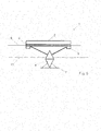
- a floating photovoltaic element 1 comprises a photovoltaic surface 2, auxiliary buoys 5 connected to the photovoltaic surface 2, a buoy 4 and a fastening system 8 connecting the buoy 4 to the photovoltaic surface 2.
- the floating of a floating photovoltaic element 1 is mainly provided by its or buoys 4.
- the flotation can also be provided by at least one cable 6 exerting a force on this element with at least one vertical component pointing upwards.
- the buoy 4 is almost sufficient to support the photovoltaic surface 2, only a residual load less than the load borne by the buoy 4 being supported by at least one cable 6.
- the auxiliary buoys 5 support this auxiliary charge when the cables 6 are relaxed.
- the floating photovoltaic element 1 is connected to the network by at least one cable 6 on each side of the photovoltaic surface 2.
- These cables can be connected to the buoy 4, so as to allow the pivoting of the entire buoy with the photovoltaic surface, as will be seen later.
- these cables may be connected to the photovoltaic surface 2, or to the support of this surface, to allow this surface to pivot independently of the buoy 4 in the case where the fastening system comprises a ball joint.
- the floating photovoltaic element 1 is connected to each of its neighbors in the same row by two cables 6, 6 '.
- Each cable may consist of a portion of cable whose first end is connected to one side of the photovoltaic surface 2 of a first floating photovoltaic element 1 and a second end is connected to one side of the photovoltaic surface 2 of a second floating photovoltaic element 1.
- the cable 6 or the cables 6, 6 ' may each consist of a single continuous cable on which are fixed the various floating photovoltaic elements 1 of the row. A continuous cable then passes through each element.
- the floating photovoltaic element 1 is connected to each of its neighbors in the same row by a single cable 6.
- the photovoltaic surface 2 can then be positioned off-center with respect to the buoy that supports it. to switch under its own weight when the cable tension is released.
- a photovoltaic surface 2 may comprise several rows of photovoltaic panels fixed on a support 3. In the embodiment shown in FIG. figure 2 each row has nine photovoltaic panels and the photovoltaic surface comprises five rows of panels.
- the photovoltaic surface may also consist of a single panel or an arbitrary surface of amorphous material.
- Photovoltaic panels can be commercial crystalline photovoltaic panels. They are advantageously mounted on a sawtooth, each being oriented obliquely with respect to the support 3, with an angle which depends on the latitude, so as to ensure an optimum illumination direction even when the support is oriented differently. This angle can advantageously be adjusted individually, either manually during assembly, or by means of cables, or other actuators to control this orientation at any time after installation.
- the number of rows and photovoltaic panels per row is chosen in order to obtain a photovoltaic surface 2 and a floating photovoltaic element 1 transportable by truck, cable car, helicopter or any other means.
- the length and the width of each photovoltaic surface are advantageously between 2 and 25 meters.
- Much larger photovoltaic elements for example of the order of 100 x 100 meters, can also be used.
- the assembly of the photovoltaic surface 2 with the fixing system 8 to obtain a floating photovoltaic element 1 can take place before transport or at the installation site of the network.
- a fast assembly mode is used by means of clips or removable fixing means along a cable, for example by clamping the cable.
- the cable may also be attached to buoy 4.
- the floating photovoltaic element is preferably mounted at a fixed position on the cable.
- the fastening system 8 connects the support 3 and the photovoltaic surface to a ring-shaped buoy 4 in this example.
- the fastening system 8 comprises a ball joint.
- the ball joint allows the photovoltaic surface to rotate around any horizontal axis.
- Ball joints allowing the photovoltaic surface to pivot along a single axis (hinge), or in a discrete number of axes, can also be imagined. Fixing systems without a ball joint, in which the photovoltaic surface remains fixed relative to the buoy, can also be used. In the latter case, the inclination of the photovoltaic surfaces is done by pivoting the buoy in the water, as will be seen below.
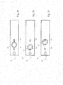
- the figure 4 illustrates a side view of a floating photovoltaic element 1 comprising a windbreak 10.
- the floating photovoltaic elements 1 are interconnected so as to form a matrix of rows and columns.
- the floating photovoltaic elements 1 of the external lines are equipped with windbreaks, each windshield protecting all the elements of a row.
- the figure 5 illustrates a side view of a floating photovoltaic element 1 according to a second embodiment.
- a floating photovoltaic element 1 comprises a photovoltaic surface 2, a support 3, auxiliary buoys connected to the support 3, a buoy 4 and a fastening system 8 connecting the buoy 4 to the support 3.
- the shape of the buoy 4 corresponds to two superimposed cones. This shape allows the buoy to pivot easily around any horizontal axis. It has a buoy base 7 which in this case is integral with the buoy.
- the buoy base 7 allows to put the buoy on the bottom of the lake without damaging it, even if the buoy is pulled on a stony bottom.
- the buoy base 7 may for example be made of metal, for example stainless steel, or hard plastic.
- the fastening system 8 of the figure 5 can also be rigid, or comprise a ball joint allowing the photovoltaic surface 2 to pivot relative to the buoy 4 around one or more horizontal pivot axes.
- the Figures 6, 7 and 8 illustrate a network of floating photovoltaic elements 1 installed on a water basin with different levels of water 13.
- the two ends of the cables 6 are attached to fastening elements 11 having a buoy 4.
- the fastening elements may for example be constituted by a tensioned cable for fixing the buoy 4 at the bottom, or a mat along which the buoy 4 can slide.
- the figure 6 corresponds to a high water level.
- the figure 7 corresponds to a water level 13 lower than that of the figure 6 .
- the buoys 4 descend along the fastening elements 11, which allows the cables 6 to remain stretched.
- the direction of displacement is vertical in this figure, a horizontal or oblique direction could however be considered.
- the figure 8 illustrates a positioning of the network of floating photovoltaic elements 1 when the water basin is empty or almost empty.
- the buoys 4 of the fastening elements 11 have reached the lower end of the fastening elements 11.
- the tension of the cables 6 between these fastening elements and the photovoltaic elements at the edge of the grating is modified by means of expansion elements compared to the situation of Figures 6 and 7 , in order to take account of the vertical displacement of the elements 1 towards the bottom 14 of the basin.
- the expansion element may for example be constituted by a winder for changing the length of the cable between the photovoltaic elements at the edge of the network and the fastening elements 11.
- mooring elements 12 are previously installed on the bottom 14 of the basin; the photovoltaic elements 1 come to rest on these fixed mooring elements. It is also possible to install at least some photovoltaic elements 1 directly on the bottom.
- FIGS 9, 10 and 11 illustrate another network of floating photovoltaic elements 1 equipped with adjustment members 9 and placed on an aquatic basin having different water levels.
- the organs of adjust the length and / or cable tension between two adjacent elements.
- the figure 9 represents a network of floating photovoltaic elements 1 on a water basin with a high water level, in which two of the floating photovoltaic elements 1 are connected by a cable provided with an adjusting member 9 of the length of the cable.
- the figure 10 represents a network of floating photovoltaic elements 1 on a water basin with a lower water level.
- the cables 6 have been relaxed between two adjacent elements, by means of the adjusting members 9, in order to take account of the vertical displacement of the elements.
- mooring elements 12 are provided on the bottom 14 of the basin in order to retain the photovoltaic elements 1.
- the buoys are fixed rigidly to the support 3 of the photovoltaic surface 2.
- adjustment can for example be constituted by winders to change the length of the cable between two photovoltaic elements.
- the figure 11 represents a network of floating photovoltaic elements 1 on an empty water basin.
- the cables 6 have been relaxed in order to adapt the length of the network to the distance to the ground between the two ends of the network.
- the length of the cables can thus be adjusted automatically or with human intervention between the position illustrated on the figure 9 , in which the photovoltaic elements 1 float on a lake or a solid reservoir, to the position illustrated in FIG. figure 11 in which these elements 1 rest on the bottom of the lake or tank, or on supports 12 hosting the photovoltaic elements on the bottom, passing through all levels of intermediate water. It is also possible, for example, that certain photovoltaic elements rest on the banks of the lake or partially emptied tank, while others continue to float.
- the tension of the cables 6 when the water level drops is adjusted and lengthened gradually, so as to ensure a sufficient voltage between the different photovoltaic elements and thus ensure that they arise in an orderly manner on the bottom or on supports 12 provided on the bottom, regularly spaced, and without turning.
- a limited length variation between the photovoltaic elements 1 may be provided to enable them to land on an irregular background.
- the voltage of the various cable sections 6 between the elements 1, and between the elements and the edge of the basin can be controlled so as to correct the orientation of the photovoltaic surfaces when the photovoltaic elements rest on a bottom which is not necessarily dish.
- the correction may for example be provided by means of a tensioner which tends or relaxes a cable 6 when one of the photovoltaic elements 1 no longer floats.
- the amplitude of the correction can be memorized mechanically or electronically during installation, depending on the inclination of the photovoltaic surfaces when they rest on the bottom.
- the correction may be triggered automatically by a mechanism detecting that the buoy is touching the bottom, or by means of a mechanism capable of triggering a correction when the level of the lake falls below a threshold.
- FIGS. 12, 13 and 14 illustrate a network of floating photovoltaic elements 1 provided with securing elements 12, adjusting members 9 and placed on a water basin with a variable water level 13.
- lashing elements 12 are pre-installed on the bottom of the water basin. When the lake is empty, part of the floating photovoltaic elements 1 can thus land on it.
- the securing elements are provided so as to correctly orient the photovoltaic elements 1 which rest on it.
- the buoys 4 of the floating photovoltaic elements 1 rest on the securing elements 12. At least one of the central elements is placed in a non-predetermined position at the bottom of the basin; this element is separated from its neighbors in the same row by cable portions of variable length.
- the photovoltaic surfaces 2 of the floating photovoltaic elements 1 rest on the securing elements 12.
- a floating photovoltaic element 1 can be connected to a securing element 12 for example by means of a cable which makes it possible to ensure a precise setting of the photovoltaic element on the element of FIG. stowage.
- the figure 15 illustrates a portion of a network of floating photovoltaic elements 1 placed on the bottom 14 of an empty aquatic pond according to an embodiment of the floating photovoltaic elements 1. It can be seen that different photovoltaic surfaces are oriented differently according to the slope of the bottom of the lake.
- the tension of the cables 6 may advantageously be adjusted to at least partially compensate for the variable distances between elements of the network when the buoys land on the bottom, in order to avoid significant tensions.
- the tension of the cables 6 can also be adjusted to correct the orientation of the different photovoltaic modules that are based on the non-flat bottom
- the figure 16 illustrates a portion of a network of floating photovoltaic elements 1 placed on the bottom 14 of an empty water basin according to another embodiment.
- Mooring elements 12 for example civil engineering elements, are fixed beforehand on the bottom 14 of the basin in order to allow the floating photovoltaic elements 1 to land on these mooring elements in an optimal position when the lake is empty.
- Each buoy can be connected to a mooring element by means of a vertical cable. The shape of the mooring element automatically centers the buoy that lands on it, even if the buoy is slightly offset due to swell or tension in the cables, for example.
- This figure also illustrates the variation in the spacing between the buoy 4 and the photovoltaic surface 2 in order to improve the positioning of the floating photovoltaic elements on the bottom of the basin when it presents differences in levels.
- the figure 17 illustrates a network of floating photovoltaic elements 1 placed on the bottom of an empty water basin according to another embodiment. Once the floating photovoltaic elements 1 attached to the docking elements 12, the cable can be released. This embodiment makes it possible, in particular, to place the floating photovoltaic elements 1 on different stages at different altitudes.
- FIGS. 18a, 18b and 18c illustrate several embodiments of an attachment element of the network of photovoltaic elements floating on the bottom of an aquatic basin.
- fastening elements 14 provided with buoys 4 make it possible to adjust the adjusting elements 9 of the cables 6 at the variable level of the lake.
- the fastening elements 14 are preferably placed at the bottom of the lake. and thus avoid any construction on the banks.
- the figure 18a illustrates a fastening element 11 of the pillar type, fixed on the bottom 14 of a basin, comprising a buoy 4. At the top of the pillar is fixed a horizontal axis whose two ends correspond to the attachment points of the ends of two cables 6 Two adjusting members 9 are positioned at the ends of the cables 6.
- the figure 18b illustrates a fastening element 11 comprising two pillars, fixed on the bottom 14 of a basin, each comprising a buoy 4. At the top of each of the two pillars is fixed an end of a cable 6. The tops of the two pillars are connected by a horizontal axis. Two adjustment members 9 of the tension of the cables are positioned at the ends of the cables 6.
- the figure 18c illustrates a fastening element 11 comprising three pillars, fixed on the bottom 14 of a basin, each comprising a buoy 4. At the top of each pillar is fixed an end of a cable 6. Two adjustment members 9 are positioned at cable ends 6.
- the Figures 19, 20 and 21 illustrate an example of a regulator in three different modes of operation.
- This device makes it possible to manually and / or automatically adjust the voltage in one of the cables 6 connecting the photovoltaic elements of one row, or of several rows on the same winder 15.
- the inclination of all the photovoltaic surfaces 2 of the row is thus controlled by means of the same winder 15, or a winder 15 at each of the two ends of the cable 6.
- This adjustment member 9 may be provided on the ground, on the edge of the water.
- the figure 19 illustrates an adjusting member 9 having a reel 15 around which is wound a portion of the cable 6.
- the adjusting member 9 comprises a spring for adjusting the tension of the cable 6 to maintain a constant target voltage of the cable 6 when the level 13 water basin varies. In this mode of operation, the cable tension 6 is adjusted without requiring additional energy. It is preferably adjusted with a counterweight or a spring.
- the figure 20 illustrates the same adjustment member 9 in which the winder 15 is moved towards the cable 6, blocking it around a stop 16
- This relaxation position allows to relax the cable 6 and reduce the desired voltage.
- This mode of operation allows in particular the pivoting of the photovoltaic surfaces 2 in particular for the tilting of the snow and / or the tracking of the maximum insolation (tracking) and / or the management of the formation of the ice.
- This mode of operation also makes it possible to lower the level of the photovoltaic surfaces 2 to bring them closer to the water level and to allow the cooling of the photovoltaic modules by a specific device.
- This operating mode of the adjustment member 9 corresponds to a motorized translation and requires a small amount of energy.
- the figure 21 illustrates the same adjusting member 9 in a position in which the winder is moved in the opposite direction to the cable, so as to tension the cable, blocking the winder on the second stop 17 to increase the target voltage.
- the cable 6 is then strongly tensioned, for example in order to place the network of floating photovoltaic elements 1 in a safety position in the event of strong winds or as a pivot axis in order to limit the influence of the wind.
- the adjustment member 9 illustrated in these figures can be operated manually. It is also possible to motorize this member, to control electrically the tension of the reel and / or the movement of the reel in a position of relaxation, maximum or intermediate voltage. Other manual, electrical or numerically controlled adjustment devices can be imagined.
- the setpoint voltage can also be varied continuously, for example to vary the inclination of the photovoltaic surfaces continuously.
- a sun and / or wind and / or snow sensor may be provided in order to automatically control the voltage to be applied, so as to automatically correct the inclination of all the surfaces of a row, or even all the surfaces of the network.
- Adjusting members 9 may also be provided between certain floating photovoltaic elements 1, in order to individually adjust the distance between two adjacent elements of a row. Springs or elements of variable length can be provided between different elements to absorb voltage variations.
- FIG. 22, 23 and 24 illustrate a floating photovoltaic element 1 in different inclinations.
- This element comprises two cables 6 and 6 'on each of the two opposite sides, as in the variant of FIG. figure 2 .
- the figure 22 illustrates the floating photovoltaic element 1 in a horizontal position. Its flotation is ensured by the tension of the two cables 6 and 6 'on each side and, to a greater extent, by the buoy located at the waterline. The sufficient voltage of the two cables 6, 6 'keeps the photovoltaic surface 2 horizontal and above the water.
- the figure 23 illustrates the photovoltaic surface 2 in an inclined position. This position makes it possible in particular to monitor the maximum amount of sunlight (tracking) or to clear snow from the photovoltaic surfaces 2.
- the cable 6 ' is relaxed while the other cable 6 can be stretched or relaxed.
- the photovoltaic surface 2 is thus unbalanced and pivots about a horizontal axis substantially parallel to the cables 6.
- the advantage of the network of floating elements of the invention is to use the cable 6 to rotate the photovoltaic surfaces without requiring extreme tension cable. This allows the cable 6 not to be released to the center of the network.
- the pivoting can be obtained by a rotation of the buoy 4 in the water, or by means of a ball joint by a pivoting of the photovoltaic surface 2 relative to the buoy 4 which remains essentially fixed.
- the figure 24 illustrates the floating photovoltaic element 1 in a lowered horizontal position with respect to the figure 22 .
- the two cables 6 are relaxed so as to maintain a horizontal position of the photovoltaic surface and thus bring it closer to the level of the water 13, in a position suitable for cooling.
- the auxiliary buoys 5 make it possible to ensure the floatation and stability of the floating element, despite the relaxation of the cables 6.
- the pivoting angle of the photovoltaic surface is controlled by the voltage of the cables 6 taking into account, if necessary, the unbalance of the photovoltaic surface.
- the horizontal position of the figure 22 can be obtained by an equal tension on the two cables 6 and 6 '; advantageously, the fixing position of the cables with respect to the pivot axis, and the imbalance of the element, are chosen so that an equal tension on the two cables 6, 6 'positions the photovoltaic surface in such a way that optimal compared to the average position of the sun during the year.
- the cables 6, 6 ' are almost horizontal when the photovoltaic surface is in the rest position of the figure 22 .
- the vertical component of the force exerted by these cables on the elements 1 is therefore small. It is possible to attach the cables in an oblique direction from one element to another, so as to increase this vertical component. It is also possible to rotate the photovoltaic floating elements 1, or photovoltaic surfaces on these elements, by means of cables perpendicular to the pivot axis.
- the cables 6, 6 connect all the floating photovoltaic elements of a row, whose inclination is thus controlled simultaneously by acting on these two cables.
- at least some floating photovoltaic elements may be connected to additional cables to control their inclination independently of that of the other elements of the same row.
- the orientation of at least some panels can optionally be controlled individually, by means of additional cables or other mechanical or electromechanical actuators.
- the tilting of the photovoltaic surface 2 can be carried out continuously, by the continuous expansion of one of the cables 6 or by shaking also by means of the cables 6.
- the available height between the panels of the photovoltaic surface 2 and the water surface 13, possibly frozen, is sufficient to accumulate the snow fallen photovoltaic modules.
- it is intended to use double-sided photovoltaic modules on the photovoltaic surfaces 2.
- the rear face of the double-sided photovoltaic modules remains naturally cleared thanks to its orientation. Thus, its operation releases heat to clear the other side by melting snow.
- the figure 25 illustrates a view from above of a network of floating photovoltaic elements 1 according to a particular embodiment.
- floating photovoltaic elements 1 have been arranged to represent a pattern or a logo.
- the pattern corresponds to the letter "L".
- additional cables and / or additional winders between the floating photovoltaic elements are necessary to individually move the floating photovoltaic elements and change the distance between these elements.
- transverse stabilization system for the distance between the rows of floating photovoltaic elements.
- This system aims to ensure a distance between certain floating photovoltaic elements, at regular intervals.
- This transverse stabilization system can be at the level of the buoys so as not to modify the inclination of the photovoltaic surfaces 2.
- logos or any type of pattern can be represented on a network of floating photovoltaic elements 1, by modifying the position of the floating photovoltaic elements 1.
- the network of floating photovoltaic elements 1 can thus be used as display structure.
- the positioning of the cables 6 is in parallel lines.
- the floating photovoltaic elements 1 are arranged in parallel lines.
- the electrical energy supplied by the photovoltaic modules in the form of a direct current is converted into alternating current at the desired voltage by means of unrepresented inverters.
- These inverters can be located both on floating photovoltaic elements 1 and outside.
Landscapes
- Engineering & Computer Science (AREA)
- Chemical & Material Sciences (AREA)
- Mechanical Engineering (AREA)
- Combustion & Propulsion (AREA)
- Life Sciences & Earth Sciences (AREA)
- Physics & Mathematics (AREA)
- Sustainable Development (AREA)
- Sustainable Energy (AREA)
- Thermal Sciences (AREA)
- General Engineering & Computer Science (AREA)
- Structural Engineering (AREA)
- Civil Engineering (AREA)
- Ocean & Marine Engineering (AREA)
- Architecture (AREA)
- Photovoltaic Devices (AREA)
Abstract
Description
La présente invention concerne un réseau d'éléments photovoltaïques flottants agencé pour être déployé en milieu aquatique.The present invention relates to an array of floating photovoltaic elements arranged to be deployed in an aquatic environment.
Le déploiement de centrales photovoltaïques à grande échelle pose des problèmes liés au manque de terrains présentant une surface suffisante et en particulier au coût de ces terrains. Ces inconvénients ont poussé quelques acteurs du domaine photovoltaïques à orienter leurs installations vers des surfaces aquatiques à grande échelle telles que les océans, mers ou lacs.The deployment of large-scale photovoltaic plants poses problems related to the lack of land with sufficient surface area and in particular the cost of these lands. These disadvantages have pushed some photovoltaic actors to orient their installations towards large-scale aquatic surfaces such as oceans, seas or lakes.
Le concept d'« île solaire » est apparu. Ce type d'installation est notamment décrit dans le document
Le document
Le document
Le document
Les centrales photovoltaïques doivent s'adapter aux contraintes de la nature (ensoleillement, enneigement, etc.) et du milieu naturel spécifique dans lequel elles sont installées (zones d'ombre des montagnes, variations du niveau des lacs, température, etc.)Photovoltaic power plants must adapt to the constraints of nature (sunshine, snow cover, etc.) and the specific natural environment in which they are installed (mountain shadows, lake level variations, temperature, etc.)
En dehors de ces systèmes déployés en milieu aquatique, il existe des systèmes terrestres permettant à des panneaux solaires d'être orientés de manière variable.Apart from these systems deployed in the aquatic environment, there are terrestrial systems allowing solar panels to be oriented in a variable manner.
Le document
Ce système de support est conçu pour être fixé sur terre. Il n'est adapté qu'à un faible nombre de réflecteurs dont le poids est entièrement supporté par les câbles. Il présente en outre l'inconvénient de nécessiter plusieurs câbles et de supporter un nombre restreint de réflecteurs.This support system is designed to be fixed on the ground. It is suitable only for a small number of reflectors whose weight is fully supported by the cables. It also has the disadvantage of requiring several cables and supporting a small number of reflectors.
Le brevet américain
La demande internationale
La demande de brevet
La demande de brevet
Il existe donc un besoin d'un réseau d'éléments photovoltaïques qui permette d'éviter au moins un des désavantages des dispositifs connus mentionnés.There is therefore a need for a network of photovoltaic elements that makes it possible to avoid at least one of the disadvantages of the known devices mentioned.
Un but de la présente invention est de proposer un réseau d'éléments photovoltaïques flottants exempt des limitations des réseaux connus.An object of the present invention is to provide an array of floating photovoltaic elements free from the limitations of known networks.
Un autre but de la présente invention est de proposer une solution alternative aux réseaux d'éléments photovoltaïques flottants existants.Another object of the present invention is to propose an alternative solution to existing photovoltaic floating element arrays.
Selon l'invention, ce but est atteint notamment au moyen d'un réseau d'éléments photovoltaïques flottants selon la revendication 1, et d'une méthode de positionnement d'un réseau d'éléments photovoltaïques flottants selon la revendication 14.According to the invention, this object is achieved in particular by means of an array of floating photovoltaic elements according to
Cette solution possède notamment l'avantage par rapport à l'art antérieur de modifier l'orientation des éléments photovoltaïques flottants sans nécessiter impérativement de dispositif actuateur propre à chaque élément photovoltaïque.This solution has the advantage over the prior art of modifying the orientation of floating photovoltaic elements without necessarily requiring actuator device specific to each photovoltaic element.
Cette solution possède également l'avantage par rapport à l'art antérieur de présenter un réseau d'éléments photovoltaïques flottants qui s'adapte aux variations même importantes du niveau des lacs. Cette solution est ainsi en particulier adaptée aux lacs de barrage.This solution also has the advantage over the prior art of presenting a network of floating photovoltaic elements that adapts to even large variations in the level of lakes. This solution is thus particularly adapted to the dam lakes.
Le réseau d'éléments photovoltaïques flottants selon l'invention comprend au moins un élément photovoltaïque flottant et au moins un câble pour relier les éléments photovoltaïques flottants entre eux. Chaque élément photovoltaïque flottant comprend une bouée et une surface photovoltaïque fixée sur la bouée. Au moins une surface photovoltaïque peut pivoter autour d'un axe horizontal, sensiblement parallèle au câble, le câble permettant d'adapter l'angle de pivotement en modifiant sa tension.The network of floating photovoltaic elements according to the invention comprises at least one floating photovoltaic element and at least one cable for connecting the photovoltaic elements floating between them. Each floating photovoltaic element comprises a buoy and a photovoltaic surface fixed on the buoy. At least one photovoltaic surface can pivot about a horizontal axis, substantially parallel to the cable, the cable to adapt the pivot angle by changing its voltage.
Dans le contexte de l'invention, l'expression « sensiblement parallèle » signifie que l'angle entre l'axe de pivotement de la surface photovoltaïque et le câble peut être compris entre + 25° et - 25°, et de préférence entre + 10° et - 10°.In the context of the invention, the expression "substantially parallel" means that the angle between the pivot axis of the photovoltaic surface and the cable may be between + 25 ° and -25 °, and preferably between + 10 ° and - 10 °.
Le réseau d'éléments photovoltaïques flottants comporte avantageusement au moins deux éléments photovoltaïques adjacents reliés par une portion de câble de longueur variable en fonction de la position verticale de ces deux éléments. Ainsi, lorsqu'un de ces deux éléments, ou les deux éléments, se posent sur le fond d'un lac vide, la longueur de ces portions de câbles est adaptée de préférence automatiquement afin de tenir compte de la distance verticale entre ces deux éléments.The array of floating photovoltaic elements advantageously comprises at least two adjacent photovoltaic elements connected by a cable portion of variable length depending on the vertical position of these two elements. Thus, when one of these two elements, or both elements, arise on the bottom of an empty lake, the length of these cable portions is preferably adapted automatically to take into account the vertical distance between these two elements. .
Le réseau d'éléments photovoltaïques flottants comporte avantageusement au moins un élément photovoltaïque relié à un point fixe au bord du plan d'eau par une portion de câble de longueur variable en fonction de la position verticale de cet élément. Ainsi, lorsque le niveau du lac descend, la longueur de cette portion de câble est adaptée de préférence automatiquement afin de tenir compte de la distance verticale variable entre le point fixe et l'élément photovoltaïque.The array of floating photovoltaic elements advantageously comprises at least one photovoltaic element connected to a point fixed at the edge of the water body by a portion of cable of variable length as a function of the vertical position of this element. Thus, when the level of the lake goes down, the length of this portion of cable is preferably adapted automatically to take into account the variable vertical distance between the fixed point and the photovoltaic element.
Dans le contexte de l'invention, on entend par surface photovoltaïque un ensemble comprenant un ou plusieurs panneaux photovoltaïques susceptibles de transformer l'énergie solaire en énergie électrique. Des panneaux photovoltaïques disponibles dans le commerce peuvent être utilisés comme panneaux photovoltaïques. Les différents panneaux photovoltaïques d'une surface photovoltaïque peuvent être disposés en dents de scie ou horizontalement ou de tout autre manière sur un support. De préférence, les panneaux photovoltaïques sont recouverts d'un matériau polymère hydrophobe. Des panneaux photovoltaïques double face peuvent être utilisés. La surface photovoltaïque peut être réalisée à partir de matériau photovoltaïque cristallin ou amorphe.In the context of the invention, the term photovoltaic surface means an assembly comprising one or more photovoltaic panels capable of transforming solar energy into electrical energy. Commercially available photovoltaic panels can be used as photovoltaic panels. The different photovoltaic panels of a photovoltaic surface can be arranged sawtooth or horizontally or in any other way on a support. Preferably, the photovoltaic panels are covered with a hydrophobic polymeric material. Double-sided photovoltaic panels can be used. The photovoltaic surface can be made from crystalline or amorphous photovoltaic material.
Par réseau d'éléments photovoltaïques flottants on entend un ensemble d'éléments photovoltaïques flottants reliés entre eux. Chaque élément photovoltaïque comporte une surface photovoltaïque et une bouée. Le réseau peut être matriciel, c'est-à-dire formé d'éléments arrangés en lignes et en colonnes. Le réseau peut aussi présenter d'autres configurations. Les éléments du réseau sont avantageusement reliés entre eux par des câbles.By floating photovoltaic element network is meant a set of floating photovoltaic elements connected to each other. Each photovoltaic element comprises a photovoltaic surface and a buoy. The network may be matrix, that is to say formed of elements arranged in rows and columns. The network may also have other configurations. The elements of the network are advantageously interconnected by cables.
Par bouée, on entend tout dispositif permettant de faire flotter au moins partiellement une surface photovoltaïque. La poussée d'Archimède exercée sur l'élément photovoltaïque flottant compense au moins partiellement le poids de cet élément. Des bouées de géométries différentes peuvent être utilisées dans le contexte de l'invention. Une bouée est réalisée de manière à permettre le réglage de l'angle de pivotement et de la position de l'élément photovoltaïque flottant.Buoy means any device for floating at least partially a photovoltaic surface. The buoyancy force exerted on the floating photovoltaic element at least partially offsets the weight of this element. Buoys of different geometries can be used in the context of the invention. A buoy is made to allow adjustment of the pivot angle and the position of the floating photovoltaic element.
La bouée, ou un élément de liaison entre la bouée et la surface photovoltaïque, est en outre avantageusement adaptée pour permettre un réglage de la hauteur de l'élément photovoltaïque flottant, afin de rapprocher ou d'éloigner la surface photovoltaïque de la surface de l'eau. La bouée peut être adaptée à reposer sur un sol dur tel que le fond d'un lac. La bouée peut comprendre une base de bouée pour protéger la bouée lorsqu'elle se pose sur un fond dur. Elle peut aussi être arrangée pour coopérer avec un élément d'amarrage reposant sur un sol dur, de manière à pouvoir se loger sur cet élément d'amarrage par exemple lorsque le niveau de l'eau descend. Des bouées de forme torique, ou en forme d'assemblage de cylindres aplatis et de triangles extrudés peuvent être employées. Elle peut présenter une base de bouée lui servant à reposer sur un sol dur, notamment lorsque la bouée est constituée d'un assemble de cônes extrudés dont l'extrémité inférieure est formée par la pointe d'un cône. La base de bouée peut être réalisée dans un matériau plus dur ou plus rigide que la bouée, et protéger la bouée.The buoy, or a connecting element between the buoy and the photovoltaic surface, is further advantageously adapted to allow adjustment of the height of the floating photovoltaic element, in order to bring the photovoltaic surface closer to or away from the surface of the photovoltaic surface. 'water. The buoy can be adapted to rest on hard ground such as the bottom of a lake. The buoy may include a buoy base to protect the buoy when it lands on a hard bottom. It can also be arranged to cooperate with a docking element resting on a hard ground, so as to be able to lodge on this docking element for example when the water level drops. O-shaped buoys, or in the form of an assembly of flattened rolls and extruded triangles may be employed. It may have a buoy base for resting on a hard ground, especially when the buoy consists of an assembly of extruded cones whose lower end is formed by the tip of a cone. The buoy base can be made from a harder or stiffer material than the buoy, and protect the buoy.
Le réseau d'éléments photovoltaïques flottants comprend des câbles dont la longueur est ajustable de manière à permettre la flottaison du réseau sur un bassin aquatique lorsqu'il est plein et le positionnement sur une surface dure lorsque le bassin aquatique est vide, la base des bouées étant adaptée pour reposer sur un sol dur.La longueur des câbles qui relient les bouées entre elles est suffisante pour permettre aux bouées de toucher le fond du lac ou du réservoir lorsque ces câbles sont détendus et que le lac ou réservoir est vide ; dans ce cas, la tension résiduelle dans les câbles permet de garantir que les bouées se posent de façon ordonnée sur le fond, sans se retourner et de préférence à distances régulières les unes des autres.The network of floating photovoltaic elements includes cables whose length is adjustable so as to allow the waterline to float on an aquatic basin when it is full and the positioning on a hard surface when the water basin is empty, the base of the buoys being adapted to rest on a hard ground.The length of the cables connecting the buoys between them is sufficient to allow the buoys to touch the bottom of the lake or reservoir when these cables are relaxed and the lake or reservoir is empty; in this case, the residual tension in the cables makes it possible to ensure that the buoys are placed in an orderly manner on the bottom, without turning and preferably at regular distances from each other.
La flottaison de chaque élément photovoltaïque du réseau d'éléments photovoltaïques flottants est assurée par sa ou ses bouées. En addition, la flottaison peut aussi être assurée par au moins un câble exerçant une force sur cet élément avec au moins une composante verticale orientée vers le haut. Dans ce cas, la bouée est presque suffisante pour supporter le poids de la surface photovoltaïque, seule une charge résiduelle inférieure à la charge supportée par la bouée étant supportée par les câbles.The floatation of each photovoltaic element of the network of floating photovoltaic elements is ensured by its buoy or buoys. In addition, the flotation may also be provided by at least one cable exerting a force on this element with at least one vertical component pointing upwards. In this case, the buoy is almost sufficient to support the weight of the photovoltaic surface, only a residual load less than the load borne by the buoy being supported by the cables.
L'avantage de cette caractéristique par rapport aux solutions de l'art antérieur réside dans le fait que la tension appliquée sur le ou les câbles est presque exclusivement dédiée au pivotement des surfaces photovoltaïques et dans une proportion bien moindre au support des éléments photovoltaïques.The advantage of this characteristic over the solutions of the prior art lies in the fact that the voltage applied to the cable or cables is almost exclusively dedicated to the pivoting of the photovoltaic surfaces and in a much smaller proportion to the support of the photovoltaic elements.
Dans le contexte de l'invention, on entend par câble, un câble mécanique, un câble électrique ou une combinaison des deux types de câbles. Dans le cas d'une combinaison, l'âme du câble peut être constituée d'un type de câble et est entourée l'autre type de câble. Le câble peut être constitué par une chaîne.In the context of the invention, the term cable, a mechanical cable, an electrical cable or a combination of the two types of cables. In the case of a combination, the core of the cable may consist of one type of cable and is surrounded by the other type of cable. The cable can be constituted by a chain.
Dans le contexte de l'invention, l'expression « un câble » correspond à un câble continu ou à des portions de câbles en ligne reliant entre eux plusieurs éléments photovoltaïques flottants dans une même rangée. Le câble n'est donc pas nécessairement continu, mais peut être constitué de plusieurs sections discontinues reliées entre elles par des éléments photovoltaïques, ou par d'autres éléments.In the context of the invention, the term "a cable" corresponds to a continuous cable or portions of in-line cables interconnecting several floating photovoltaic elements in the same row. The cable is not necessarily continuous, but may consist of several discontinuous sections interconnected by photovoltaic elements, or by other elements.
Dans le contexte de l'invention, le pivotement de la surface photovoltaïque permet d'en varier l'inclinaison autour d'un axe horizontal. Cette variation permet en particulier le suivi du soleil au cours de la journée et de la saison, en variant constamment la tension de câble afin d'orienter correctement les surfaces photovoltaïques. Lorsque les éléments photovoltaïques reposent sur un fond du lac pas nécessairement plat, la tension des câbles peut être ajustée afin de rectifier l'orientation des surfaces photovoltaïques.In the context of the invention, the pivoting of the photovoltaic surface makes it possible to vary its inclination around a horizontal axis. This variation allows in particular the tracking of the sun during the day and the season, by constantly varying the cable tension in order to correctly orient the photovoltaic surfaces. When the photovoltaic elements rest on a not necessarily flat bottom of the lake, the tension of the cables can be adjusted in order to rectify the orientation of the photovoltaic surfaces.
Le pivotement des surfaces photovoltaïques peut aussi être utilisé pour le déneigement de la surface photovoltaïque. Des mouvements de pivotement répétés permettent notamment d'éviter la formation de glace. Lorsque l'élément photovoltaïques flottant est pris dans la glace, il est possible de prévoir une configuration de cet élément selon laquelle la neige pourra s'évacuer toute seule pendant la période hivernale. Une telle configuration peut par exemple être obtenue en inclinant suffisamment la surface photovoltaïque. Lorsque l'élément photovoltaïque flottant est pris dans la glace, il est également possible que la surface photovoltaïques et son support pivotent pour évacuer la neige alors que le reste de l'élément photovoltaïques flottant est fixe et pris dans la glace.The pivoting of the photovoltaic surfaces can also be used for snow removal of the photovoltaic surface. In particular, repeated pivoting movements make it possible to avoid the formation of ice. When the floating photovoltaic element is caught in the ice, it is possible to provide a configuration of this element that the snow can evacuate itself during the winter period. Such a configuration can for example be obtained by sufficiently inclining the photovoltaic surface. When the floating photovoltaic element is caught in the ice, it is also possible that the photovoltaic surface and its support pivot to evacuate the snow while the rest of the floating photovoltaic element is fixed and caught in the ice.
Dans le contexte de l'invention, le pivotement des surfaces photovoltaïques s'effectue autour d'un axe horizontal. De manière équivalente les surfaces photovoltaïques flottantes peuvent pivoter autour d'un axe quasi-horizontal, ou de tout axe non vertical, afin par exemple de modifier l'inclinaison de la surface photovoltaïques en fonction de la distance zénithale du soleil.In the context of the invention, the pivoting of the photovoltaic surfaces takes place around a horizontal axis. Equivalently, the floating photovoltaic surfaces can pivot about a quasi-horizontal axis, or any non-vertical axis, for example to modify the inclination of the photovoltaic surface as a function of the zenith distance of the sun.
L'inclinaison peut aussi être contrôlée en fonction du vent, afin d'aplatir la surface en cas de fort vent par exemple.The inclination can also be controlled according to the wind, in order to flatten the surface in the event of strong wind for example.
Les éléments photovoltaïques flottants situés en périphérie du réseau c'est-à-dire sur les lignes de front du réseau, peuvent être équipés de pare-vent offrant une protection contre le vent. Ces pare vent permettent de stabiliser le réseau.The floating photovoltaic elements located at the periphery of the network, that is to say on the front lines of the network, can be equipped with windbreaks providing protection against the wind. These windshields help stabilize the network.
Les bouées des éléments photovoltaïques flottants peuvent être adaptées pour reposer sur un sol dur. L'adaptation peut par exemple consister en un matériau de la bouée, ou de la portion inférieure de la bouée, suffisamment solide et rigide pour ne pas se détruire ni se déformer si la bouée est posée ou même tractée sur un sol dur ou caillouteux, par exemple sur le fond d'un lac ou d'un réservoir. L'adaptation peut par exemple aussi consister en une forme de la bouée qui lui permet de ne pas se retourner, ni d'endommager la surface photovoltaïque, lorsque la bouée se pose sur un sol dur ou caillouteux. Comme mentionné, l'adaptation peut consister en une base solidaire de la bouée mais dans un matériau différent, et qui ne contribue pas à améliorer la flottaison. Il est aussi possible de munir l'élément photovoltaïques de pieds qui leur permettent de se poser de façon stable sur le fond ou sur un support d'accueil, par exemple de pieds de longueur et/ou d'inclinaison variable et qui s'adaptent automatiquement à la géométrie du fond du lac.The buoys of the floating photovoltaic elements can be adapted to rest on hard ground. The adaptation may for example consist of a material of the buoy, or the lower portion of the buoy, sufficiently strong and rigid not to destroy or deform if the buoy is placed or even towed on a hard or stony ground, for example on the bottom of a lake or reservoir. The adaptation may for example also consist of a shape of the buoy that allows it to not turn around or damage the photovoltaic surface, when the buoy lands on a hard or stony ground. As mentioned, the adaptation may consist of a base integral with the buoy but in a different material, and which does not contribute to improving the flotation. It is also possible to provide the photovoltaic element with feet that allow them to rest stably on the bottom or on a support, by example of feet of variable length and / or inclination and which automatically adapt to the geometry of the lake bottom.
Les bouées peuvent coopérer avec un élément d'arrimage qui repose sur un sol dur. Les bouées peuvent se poser sur cet élément d'arrimage lorsque la bouée descend, par exemple si le niveau du lac ou du réservoir baisse. Les bouées peuvent être en permanence reliées aux éléments d'arrimage correspondants, par exemple au moyen de câbles, de sangles, ou d'autres éléments flexibles. Les éléments d'arrimage peuvent aussi être solidaires des bouées, ou de certaines bouées, et flotter avec ces bouées lorsque le lac est suffisamment rempli.The buoys can cooperate with a lashing element which rests on a hard ground. Buoys may land on this securing element when the buoy descends, for example if the level of the lake or reservoir drops. The buoys may be permanently connected to the corresponding securing elements, for example by means of cables, straps, or other flexible elements. The securing elements may also be integral with the buoys, or certain buoys, and float with these buoys when the lake is sufficiently filled.
Les éléments photovoltaïques flottants comprennent en outre des bouées auxiliaires ou bouées de secours. Ces bouées peuvent être utilisées par exemple lors de la mise en place de l'élément photovoltaïque, elles lui permettent de flotter alors qu'il n'est pas encore attaché à au moins à câble. Les bouées auxiliaires peuvent également être utilisées en cas d'absence, respectivement de rupture de câble. Les bouées auxiliaires supportent en outre les éléments photovoltaïques lorsque les câbles sont détendus et n'offrent plus une traction vers le haut suffisante.The floating photovoltaic elements also comprise auxiliary buoys or emergency buoys. These buoys can be used for example during the establishment of the photovoltaic element, they allow it to float while it is not yet attached to at least cable. Auxiliary buoys can also be used in case of absence or cable break. The auxiliary buoys also support the photovoltaic elements when the cables are relaxed and no longer provide sufficient upward traction.
La surface photovoltaïque peut être liée de différentes manières à la bouée. Cette liaison peut notamment être de type mobile, par exemple au moyen d'une rotule. Dans ce cas, lorsque la surface photovoltaïque et son support pivotent, la bouée reste fixe. La rotule peut permettre la rotation de la surface photovoltaïque selon un seul axe horizontal, à la manière d'une charnière. La rotule peut aussi dans une variante permettre la rotation du support selon deux axes horizontaux, ou selon n'importe quel axe horizontal.The photovoltaic surface can be linked in different ways to the buoy. This connection may in particular be of mobile type, for example by means of a ball joint. In this case, when the photovoltaic surface and its support pivot, the buoy remains fixed. The ball joint can allow rotation of the photovoltaic surface along a single horizontal axis, in the manner of a hinge. The patella can also in a variant allow the rotation of the support along two horizontal axes, or along any horizontal axis.
Dans un autre cas, la liaison entre la surface photovoltaïque et la bouée peut également être rigide et permettre à la surface photovoltaïque et à la bouée de pivoter de manière solidaire. Dans ce cas, le pivotement de la surface photovoltaïque est effectué en pivotant la bouée dans l'eau.In another case, the connection between the photovoltaic surface and the buoy may also be rigid and allow the photovoltaic surface and the buoy to pivot integrally. In this case, the pivoting of the photovoltaic surface is performed by pivoting the buoy in the water.
Dans un mode de réalisation, la liaison entre la bouée et la surface photovoltaïque permet de modifier l'espacement vertical entre la surface photovoltaïque et la bouée. La liaison entre la surface photovoltaïque et la bouée peut permettre un mouvement de translation de la surface photovoltaïque selon un axe, par exemple selon un axe vertical. Notamment dans le cas d'un lac vide, la surface photovoltaïque peut être placée horizontalement sur un élément d'arrimage alors que la bouée repose sur le fond qui n'est pas forcément plat. Les irrégularités du fond peuvent être importantes entre les deux extrémités de la surface photovoltaïque. Il peut alors être souhaitable d'adapter l'espacement vertical entre la bouée et la surface photovoltaïque afin de ne détériorer ni la bouée ni la surface photovoltaïque.In one embodiment, the connection between the buoy and the photovoltaic surface makes it possible to modify the vertical spacing between the photovoltaic surface and the buoy. The connection between the photovoltaic surface and the buoy can allow translational movement of the photovoltaic surface along an axis, for example along a vertical axis. Especially in the case of an empty lake, the photovoltaic surface can be placed horizontally on a securing element while the buoy rests on the bottom which is not necessarily flat. The irregularities of the bottom may be important between the two ends of the photovoltaic surface. It may then be desirable to adapt the vertical spacing between the buoy and the photovoltaic surface in order to avoid damaging the buoy or the photovoltaic surface.
Les différents éléments photovoltaïques flottants du réseau peuvent être de forme carrée, rectangulaire, hexagonale ou de n'importe quelle forme adaptée à une fabrication industrielle et permettant de recouvrir efficacement la surface du plan d'eau.The various floating photovoltaic elements of the network may be square, rectangular, hexagonal or any form suitable for industrial production and to effectively cover the surface of the body of water.
Les différents éléments photovoltaïques flottants du réseau sont reliés entre eux par au moins un câble fixé sur deux côtés opposés de chaque élément photovoltaïque flottant de manière à pouvoir adapter l'angle de pivotement de ces éléments flottants en modifiant la tension du câble. Deux éléments photovoltaïques voisins peuvent par exemple être reliés par deux câbles parallèles dans un même plan horizontal.The various floating photovoltaic elements of the network are interconnected by at least one cable fixed on two opposite sides of each floating photovoltaic element so as to adapt the pivot angle of these floating elements by modifying the tension of the cable. Two adjacent photovoltaic elements can for example be connected by two parallel cables in the same horizontal plane.
La tension des câbles peut être ajustée par un système mécanique utilisant des mécanismes simples (poulie, frein, contrepoids). L'ajustement de la tension d'un câble agit sur l'inclinaison des éléments photovoltaïques flottants de la rangée d'éléments fixés sur ce câble.The tension of the cables can be adjusted by a mechanical system using simple mechanisms (pulley, brake, counterweight). The adjustment of the tension of a cable acts on the inclination of the floating photovoltaic elements of the row of elements fixed on this cable.
Une surface photovoltaïque peut être positionnée de manière décentrée par rapport à la bouée qui la supporte de manière à basculer sous son propre poids lorsque la tension du câble est relâchée. Le balourd de la surface photovoltaïque la fait alors basculer sous son propre poids lorsque les câbles sont suffisamment détendus pour permettre ce pivotement.A photovoltaic surface can be positioned off-center with respect to the buoy that supports it so as to switch under its own weight when the cable tension is released. The unbalance of the photovoltaic surface then tilts it under its own weight when the cables are sufficiently relaxed to allow this pivoting.
Dans un mode de réalisation, le pivotement des surfaces photovoltaïques est obtenu en exerçant une tension sur les câbles selon une direction comportant une composante verticale. La surface photovoltaïque peut pivoter grâce à un câble agencé pour exercer une traction selon une direction oblique orientée vers le haut ou vers le bas.In one embodiment, the pivoting of the photovoltaic surfaces is obtained by exerting a tension on the cables in a direction comprising a vertical component. The photovoltaic surface can rotate by means of a cable arranged to exert traction in an oblique direction oriented upwards or downwards.
Dans un mode de réalisation, deux câbles, au moins, sont fixés sur les deux côtés opposés de chaque élément photovoltaïque flottant de manière à pouvoir adapter l'angle de pivotement en modifiant la tension d'au moins un des deux câbles.In one embodiment, at least two cables are attached to the two opposite sides of each floating photovoltaic element so that the pivot angle can be adjusted by changing the voltage of at least one of the two cables.
Afin de pivoter les éléments photovoltaïques flottants, la tension d'au moins un des câbles est modifiée. Cette modification est effectuée grâce à au moins un organe de réglage. Ce dernier est agencé pour enrouler ou dérouler une portion du câble.In order to pivot the floating photovoltaic elements, the voltage of at least one of the cables is changed. This modification is performed by at least one adjusting member. The latter is arranged to wind or unroll a portion of the cable.
Dans le contexte de l'invention, l'organe de réglage remplit plusieurs fonctions. Dans un cas, il est agencé pour maintenir une tension constante du câble. Plusieurs organes de réglages peuvent être prévus sur le réseau d'éléments photovoltaïques flottants.In the context of the invention, the adjustment member performs several functions. In one case, it is arranged to maintain a constant voltage of the cable. Several adjustment members may be provided on the floating photovoltaic array.
Dans un autre cas, lorsqu'il est nécessaire de faire pivoter les éléments photovoltaïques, l'organe de réglage est susceptible de tendre ou détendre au moins un câble.In another case, when it is necessary to rotate the photovoltaic elements, the adjustment member is able to tension or relax at least one cable.
Le réglage de la tension des câbles peut être effectué de manière automatique ou manuelle.The tensioning of the cables can be adjusted automatically or manually.
En cas de vents forts par exemple, il sera nécessaire de placer le réseau d'éléments photovoltaïques flottants dans une position de sécurité. Dans ce cas, l'organe de réglage peut tendre ou détendre au moins les câbles, de manière automatique, afin de placer les surfaces dans cette position de sécurité. La position de sécurité peut par exemple être une position dans laquelle les surfaces sont horizontales et offrent ainsi moins de prise au vent.In case of strong winds for example, it will be necessary to place the network of floating photovoltaic elements in a safety position. In this case, the adjustment member can at least automatically tension or relax the cables in order to place the surfaces in this safety position. The safety position can for example be a position in which the surfaces are horizontal and thus offer less wind grip.
Dans d'autres situations la position des éléments photovoltaïques et donc la tension d'au moins un câble peut également être modifiée automatiquement. Il s'agit notamment du suivi de la position du soleil, du déneigement des éléments photovoltaïques et de la détection de la glace.In other situations the position of the photovoltaic elements and therefore the voltage of at least one cable can also be changed automatically. These include monitoring the position of the sun, clearing snow from photovoltaic elements and detecting ice.
Lorsque la température des surfaces photovoltaïques est trop élevée, il est nécessaire de les refroidir. En fonctionnement, les surfaces photovoltaïques chauffent, leur température s'élève et leur rendement électrique diminue. Leur refroidissement permet ainsi d'augmenter le rendement électrique. Les surfaces photovoltaïques sont déjà refroidies grâce au vent. Les surfaces photovoltaïques peuvent être refroidies avec de l'eau, en baissant la surface photovoltaïque ou l'ensemble de l'élément photovoltaïque flottant jusqu'à ce que les panneaux photovoltaïques entrent en contact avec l'eau. Cette opération peut être effectuée en modifiant la tension des câbles afin de rapprocher les surfaces photovoltaïques de la surface de l'eau. Dans un autre cas, de l'eau pourrait également être pulvérisée sur les panneaux photovoltaïques. Dans un autre cas encore de l'eau peut circuler en contact thermique avec les panneaux photovoltaïques.When the temperature of the photovoltaic surfaces is too high, it is necessary to cool them. In operation, the photovoltaic surfaces heat, their temperature rises and their electrical efficiency decreases. Their cooling thus makes it possible to increase the electrical efficiency. Photovoltaic surfaces are already cooled by wind. The photovoltaic surfaces can be cooled with water, by lowering the photovoltaic surface or the entire floating photovoltaic element until the photovoltaic panels come into contact with the water. This operation can be carried out by modifying the tension of the cables in order to bring the photovoltaic surfaces closer to the surface of the water. In another case, water could also be sprayed on the photovoltaic panels. In yet another case water can circulate in thermal contact with the photovoltaic panels.
On peut également prévoir un système permettant l'échange de chaleur entre l'eau et les surfaces photovoltaïques.It is also possible to provide a system for exchanging heat between the water and the photovoltaic surfaces.
Lors des variations du niveau d'eau sur laquelle flotte le réseau d'éléments photovoltaïques, il est également avantageux de modifier la tension des câbles reliant les différents éléments photovoltaïques flottants. Cette modification de la tension permet notamment d'adapter la forme du réseau à la forme de la surface d'eau sur laquelle il flotte. En effet, une baisse du niveau d'eau d'une retenue peut entrainer une réduction de la surface d'eau sur laquelle flotte le réseau d'éléments photovoltaïques. Cette modification de la tension des câbles peut également être effectuée automatiquement.During variations in the water level on which the array of photovoltaic elements floats, it is also advantageous to modify the voltage of the cables connecting the various floating photovoltaic elements. This modification of the voltage makes it possible in particular to adapt the shape of the network to the shape of the water surface on which it floats. In fact, a drop in the water level of a reservoir can lead to a reduction in the water surface on which the photovoltaic elements network is floating. This change in cable tension can also be done automatically.
Afin de modifier automatiquement la tension des câbles du réseau d'éléments photovoltaïques flottants, un organe de réglage comprenant un module électronique peut être prévu. Ce module électronique permet notamment de détecter le niveau d'enneigement, la présence ou le risque de glace, le degré d'ensoleillement, la vitesse du vent, le niveau du lac et/ou encore la température des surfaces photovoltaïques et de contrôler l'orientation des surfaces photovoltaïques en fonction d'un de ces paramètres, ou de n'importe quelle combinaison entre deux ou plusieurs de ces paramètres. Des consignes manuelles peuvent aussi être introduites par un opérateur.In order to automatically change the voltage of the cables of the network of floating photovoltaic elements, an adjusting member comprising an electronic module may be provided. This electronic module makes it possible in particular to detect the snow level, the presence or the risk of ice, the degree of sunshine, the wind speed, the level of the lake and / or the temperature of the photovoltaic surfaces and to control the orientation of the photovoltaic surfaces according to one of these parameters, or any combination between two or more of these parameters. Manual instructions can also be entered by an operator.
Le module électronique peut être placé sur un organe de réglage supplémentaire, sur une des bouées, ou sur une station au bord du plan du plan d'eau. Plusieurs modules ou capteurs peuvent être prévus.The electronic module can be placed on an additional adjustment member, on one of the buoys, or on a station at the edge of the plane of the water body. Several modules or sensors can be provided.
La tension des câbles peut également être modifiée manuellement.The tension of the cables can also be changed manually.
Dans un mode de réalisation, les différents panneaux constituant une surface photovoltaïque peuvent pivoter indépendamment les uns des autres, et/ou indépendamment de la surface photovoltaïque. Des actuateurs indépendants, et/ou des câbles, peuvent être prévus pour effectuer ce pivotement.In one embodiment, the various panels constituting a photovoltaic surface can pivot independently of each other, and / or independently of the photovoltaic surface. Independent actuators, and / or cables, may be provided to effect this pivoting.
L'invention concerne également un système d'attache d'un réseau d'éléments photovoltaïques flottants à la surface d'un bassin aquatique comprenant au moins un élément d'attache fixé dans le fond du bassin aquatique.The invention also relates to a system for attaching a network of floating photovoltaic elements to the surface of an aquatic basin comprising at least one attachment element fixed in the bottom of the water basin.
Dans le contexte de l'invention on entend par bassin aquatique toute étendue d'eau d'une taille suffisante pour supporter un réseau d'éléments photovoltaïques flottants tels qu'un lac naturel, un lac de barrage, une mer, un océan, etc. De préférence le bassin aquatique est constitué par un lac de barrage. En particulier des lacs de barrage situés en altitude bénéficient d'un fort ensoleillement avec des températures basses ce qui présente un avantage pour les installations photovoltaïques.In the context of the invention, the term "water basin" means any body of water of sufficient size to support a network of floating photovoltaic elements such as a natural lake, a dam lake, a sea, an ocean, etc. . Preferably the water basin is constituted by a dam lake. In particular dam lakes located at high altitude benefit from strong sunshine with low temperatures, which is an advantage for photovoltaic installations.
L'invention concerne également une méthode de positionnement d'un réseau d'éléments photovoltaïques flottants comportant au moins une étape d'assemblage des éléments photovoltaïques flottants à la surface d'un bassin aquatique grâce à au moins un câble et une étape de fixation de ce câble dans le fond du bassin aquatique.The invention also relates to a method of positioning an array of floating photovoltaic elements comprising at least one step of assembling the floating photovoltaic elements on the surface of an aquatic basin by means of at least one cable and a step of fixing the photovoltaic elements. this cable in the bottom of the water basin.
Une structure comprenant au moins un câble peut être fixée dans le fond du bassin grâce à des éléments d'attache. L'étape de fixation consiste à assembler les éléments photovoltaïques flottants à cette structure de câble.A structure comprising at least one cable can be fixed in the bottom of the basin by means of fastening elements. The fixing step consists in assembling the floating photovoltaic elements to this cable structure.
Le pivotement des éléments photovoltaïques flottants peut être répété sous la forme de secousses. Ce mode de fonctionnement permet en particulier de déneiger les surfaces photovoltaïques et/ou de limiter la formation de glace. Le réglage de la tension d'au moins un câble permet aussi d'adapter le réseau d'éléments photovoltaïques flottants aux variations du niveau d'eau du bassin aquatique. Par variations du niveau d'eau, on entend différents types de variations en hauteur du niveau d'un lac. La variation journalière du niveau d'eau d'un lac de barrage peut par exemple être de quelques mètres. La variation saisonnière peut dépasser une centaine de mètres.The pivoting of the floating photovoltaic elements can be repeated in the form of jolts. This mode of operation makes it possible in particular to clear snow from the photovoltaic surfaces and / or to limit the formation of ice. Adjusting the voltage of at least one cable also makes it possible to adapt the network of floating photovoltaic elements to variations in the water level of the aquatic basin. By water level variations, we mean different types of variations in the height of a lake. The daily variation of the water level of a dam lake may for example be a few meters. The seasonal variation can exceed a hundred meters.
Le réglage de la tension d'au moins un câble permet au réseau d'éléments photovoltaïques flottants, ou à certains éléments de ce réseau de se poser à même le sol lorsque le bassin aquatique est vide ou partiellement vide.Adjusting the voltage of at least one cable allows the network of floating photovoltaic elements, or certain elements of this network to land on the ground when the water tank is empty or partially empty.
Au moins certains éléments photovoltaïques flottants peuvent être fixés à l'aide de moyens d'arrimage placés au fond du bassin aquatique lorsque le bassin aquatique est vide.At least some floating photovoltaic elements can be fixed using securing means placed at the bottom of the water basin when the water tank is empty.
Une surface photovoltaïque peut être pivotée avec un angle de pivotement différent d'une autre surface photovoltaïque de sorte que la position des éléments photovoltaïques flottants constituant le réseau représente un motif. Un exemple de motif peut être un logo. Cette étape permet ainsi d'utiliser le réseau d'éléments photovoltaïques flottants comme un support de publicité pour afficher un logo géant.A photovoltaic surface can be rotated with a pivot angle different from another photovoltaic surface so that the position of the floating photovoltaic elements constituting the grating represents a pattern. An example of a pattern can be a logo. This step thus makes it possible to use the network of floating photovoltaic elements as an advertising medium to display a giant logo.
Il est aussi possible de disposer les éléments photovoltaïques flottants constituant le réseau de sorte que leur répartition représente un motif.It is also possible to arrange the floating photovoltaic elements constituting the network so that their distribution represents a pattern.
La présente invention concerne aussi un réseau d'éléments photovoltaïques installé sur un bassin aquatique et relié aux berges du bassin par des câbles dont la longueur peut être ajustée afin de s'adapter à un niveau d'eau fluctuant caractéristique des lacs de barrage par exemple. Avantageusement, la longueur des câbles est ajustable entre une première position dans laquelle ledit réseau flotte sur ledit bassin aquatique plein et une deuxième position dans laquelle au moins certains éléments photovoltaïques reposent directement sur le fond du bassin ou sur un support (12) monté sur le fond du bassin.The present invention also relates to a network of photovoltaic elements installed on an aquatic basin and connected to the banks of the basin by cables whose length can be adjusted to adapt to a fluctuating water level characteristic of the dam lakes for example . Advantageously, the length of the cables is adjustable between a first position in which said network floats on said solid water basin and a second position in which at least some photovoltaic elements rest directly on the bottom of the basin or on a support (12) mounted on the bottom of the basin.
Des exemples de mise en oeuvre de l'invention sont indiqués dans la description illustrée par les figures annexées dans lesquelles :
- La
figure 1 illustre une vue latérale d'un élément photovoltaïque flottant selon un premier mode de réalisation. - La
figure 2 illustre une vue de dessus d'un élément photovoltaïque flottant. - La
figure 3 illustre une vue de côté d'un élément photovoltaïque flottant. - La
figure 4 illustre une vue de côté d'un élément photovoltaïque flottant comprenant un pare-vent. - La
figure 5 illustre une vue latérale d'un élément photovoltaïque flottant selon un deuxième mode de réalisation. - Les
figures 6, 7 illustrent un réseau d'éléments photovoltaïques flottants placé sur un bassin aquatique présentant plusieurs niveaux d'eau.et 8 - Les
figures 9, 10 et 11 illustrent un réseau d'éléments photovoltaïques flottants muni d'organes de réglage et placé sur un bassin aquatique présentant plusieurs niveaux d'eau. - Les
figures 12, 13 et 14 illustrent un réseau d'éléments photovoltaïques flottants muni d'éléments d'arrimage, d'organes de réglage et placé sur un bassin aquatique présentant plusieurs niveaux d'eau. - La
figure 15 illustre un réseau d'éléments photovoltaïques flottants posés sur le fond d'un bassin aquatique vide selon un mode de réalisation. - La
figure 16 illustre un réseau d'éléments photovoltaïques flottants posés sur le fond d'un bassin aquatique vide selon un autre mode de réalisation. - La
figure 17 illustre un réseau d'éléments photovoltaïques flottants posés sur le fond d'un bassin aquatique vide selon un autre mode de réalisation. - Les
figures 18a, 18b et 18c illustrent plusieurs modes de réalisation d'un élément d'attache du réseau d'éléments photovoltaïques flottants sur le fond d'un bassin aquatique. - La
figure 19 illustre un organe de réglage dans un premier mode de fonctionnement. - La
figure 20 illustre un organe de réglage dans un deuxième mode de fonctionnement. - La
figure 21 illustre un organe de réglage dans un troisième mode de fonctionnement. - Les
figures 22, 23 et 24 illustrent un élément photovoltaïque flottant dans différentes positions. - La
figure 25 illustre une vue du dessus d'un réseau d'éléments photovoltaïques flottants selon un mode de réalisation.
- The
figure 1 illustrates a side view of a floating photovoltaic element according to a first embodiment. - The
figure 2 illustrates a top view of a floating photovoltaic element. - The
figure 3 illustrates a side view of a floating photovoltaic element. - The
figure 4 illustrates a side view of a floating photovoltaic element comprising a windshield. - The
figure 5 illustrates a side view of a floating photovoltaic element according to a second embodiment. - The
Figures 6, 7 and 8 illustrate a network of floating photovoltaic elements placed on an aquatic basin presenting several levels of water. - The
Figures 9, 10 and 11 illustrate a network of floating photovoltaic elements equipped with regulators and placed on an aquatic basin presenting several levels of water. - The
Figures 12, 13 and 14 illustrate a network of floating photovoltaic elements provided with securing elements, regulators and placed on a water basin with several water levels. - The
figure 15 illustrates a network of floating photovoltaic elements placed on the bottom of an empty aquatic basin according to one embodiment. - The
figure 16 illustrates a network of floating photovoltaic elements placed on the bottom of an empty aquatic basin according to another embodiment. - The
figure 17 illustrates a network of floating photovoltaic elements placed on the bottom of an empty aquatic basin according to another embodiment. - The
Figures 18a, 18b and 18c illustrate several embodiments of an attachment element of the network of photovoltaic elements floating on the bottom of an aquatic basin. - The
figure 19 illustrates an adjusting member in a first mode of operation. - The
figure 20 illustrates an adjusting member in a second mode of operation. - The
figure 21 illustrates an adjusting member in a third mode of operation. - The
Figures 22, 23 and 24 illustrate a photovoltaic element floating in different positions. - The
figure 25 illustrates a top view of an array of floating photovoltaic elements according to one embodiment.
Les
L'élément photovoltaïque flottant 1 est relié au réseau par au moins un câble 6 de chaque côté de la surface photovoltaïque 2. Ces câbles peuvent être liés à la bouée 4, de manière à permettre le pivotement de l'ensemble de la bouée avec la surface photovoltaïque, comme on le verra plus loin. Dans un autre mode de réalisation, ces câbles peuvent être liés à la surface photovoltaïque 2, ou au support de cette surface, afin de permettre à cette surface de pivoter indépendamment de la bouée 4 dans le cas où le système de fixation comporte une rotule.The floating
Dans un mode de réalisation, l'élément photovoltaïque flottant 1 est relié à chacun de ses voisins dans la même rangée par deux câbles 6, 6'. Chaque câble peut être constitué par une portion de câble dont une première extrémité est reliée à un côté de la surface photovoltaïque 2 d'un premier élément photovoltaïque flottant 1 et une deuxième extrémité est reliée à un côté de la surface photovoltaïque 2 d'un second élément photovoltaïque flottant 1.In one embodiment, the floating
Dans un autre mode de réalisation, le câble 6 ou les câbles 6, 6' peuvent être constitués chacun par un seul câble continu sur lequel sont fixés les différents éléments photovoltaïques flottants 1 de la rangée. Un câble continu traverse alors chaque élément.In another embodiment, the
Dans un autre mode de réalisation l'élément photovoltaïque flottant 1 est relié à chacun de ses voisins dans la même rangée par un seul câble 6. La surface photovoltaïque 2 peut alors être positionnée de manière décentrée par rapport à la bouée qui le supporte de manière à basculer sous son propre poids lorsque la tension du câble est relâchée.In another embodiment the floating
Une surface photovoltaïque 2 peut comprendre plusieurs rangées de panneaux photovoltaïques fixées sur un support 3. Dans le mode de réalisation représenté à la
De manière générale, le nombre de rangées et de panneaux photovoltaïques par rangée est choisi afin d'obtenir une surface photovoltaïque 2 et un élément photovoltaïque flottant 1 transportables par camion, téléphérique, hélicoptère ou tout autre moyen. Par exemple, la longueur et la largeur de chaque surface photovoltaïque sont avantageusement comprises entre 2 et 25 mètres. Des éléments photovoltaïques beaucoup plus grands, par exemple de l'ordre de 100 x 100 mètres, peuvent aussi être utilisés.In general, the number of rows and photovoltaic panels per row is chosen in order to obtain a
L'assemblage de la surface photovoltaïque 2 avec le système de fixation 8 pour obtenir un élément photovoltaïque flottant 1 peut avoir lieu avant le transport ou sur le site d'installation du réseau.The assembly of the
Dans le support 3 sont prévus des moyens, non représentés, pour attacher l'élément photovoltaïque flottant 1 aux câbles 6. De préférence, on utilise un mode d'assemblage rapide grâce à des clips ou des moyens de fixation amovible le long d'un câble, par exemple par pinçage du câble. Le câble peut aussi être fixé à la bouée 4. L'élément photovoltaïque flottant est de préférence monté à une position fixe sur le câble.In the
Le système de fixation 8 relie le support 3 et la surface photovoltaïque à une bouée 4 de forme torique dans cet exemple.. Dans ce mode de réalisation, le système de fixation 8 comprend une rotule. Elle permet notamment de ne pas entraîner la bouée 4 lorsque la surface photovoltaïque 2 pivote sous l'action des câbles. La rotule permet à la surface photovoltaïque de pivoter autour de n'importe quel axe horizontal. Des rotules permettant à la surface photovoltaïque de pivoter selon un seul axe (charnière), ou selon un nombre discret d'axes, peuvent aussi être imaginées. Des systèmes de fixation sans rotule, dans lesquels la surface photovoltaïque reste fixe par rapport à la bouée, peuvent aussi être utilisés. Dans ce dernier cas, l'inclinaison des surfaces photovoltaïques se fait en pivotant la bouée dans l'eau, comme on le verra plus bas.The
La
La
Comme dans le mode de réalisation des
Les
La
La
La
Dans cet exemple, des éléments d'amarrage 12 sont préalablement installés sur le fond 14 du bassin ; les éléments photovoltaïques 1 viennent se poser sur ces éléments d'amarrage fixe. Il est aussi possible de poser au moins certains éléments photovoltaïques 1 directement sur le fond.In this example,
Les
La
La
La
Les solutions des
La tension des différents tronçons de câbles 6 entre les éléments 1, et entre les éléments et le bord du bassin, peut être contrôlée de manière à corriger l'orientation des surfaces photovoltaïques lorsque les éléments photovoltaïques reposent sur un fond qui n'est pas nécessairement plat. La correction peut par exemple être apportée au moyen d'un tendeur qui tend ou détend un câble 6 lorsqu'un des éléments photovoltaïques 1 ne flotte plus. L'amplitude de la correction peut être mémorisée de manière mécanique ou électronique lors de l'installation, en fonction de l'inclinaison des surfaces photovoltaïques lorsqu'elles reposent sur le fond. La correction peut être déclenchée automatiquement par un mécanisme détectant que la bouée touche le fond, ou au moyen d'un mécanisme capable de déclencher une correction lorsque le niveau du lac descend en dessous d'un seuil.The voltage of the
Dans un mode de réalisation non représenté, il est possible de déplacer individuellement certains des éléments photovoltaïques flottants 1, par exemple des éléments situés dans des zones d'ombre.In an embodiment not shown, it is possible to move individually some of the floating
Les
Selon un mode de réalisation, des éléments d'arrimage 12 sont préinstallés sur le fond du bassin aquatique. Lorsque le lac se vide, une partie des éléments photovoltaïques flottants 1 peut ainsi se poser dessus. Les éléments d'arrimage sont prévus de manière à orienter correctement les éléments photovoltaïques 1 qui reposent dessus.According to one embodiment, lashing
Selon un mode de réalisation représenté à la
Selon un autre mode de réalisation représenté à la
Selon un mode de réalisation non représenté, un élément photovoltaïque flottant 1 peut être relié à un élément d'arrimage 12 par exemple au moyen d'un câble qui permet d'assurer un posage précis de l'élément photovoltaïque sur l'élément d'arrimage.According to an embodiment not shown, a floating
La
La
La
Les
Dans cette variante de l'invention, des éléments d'attache 14 munis de bouées 4 permettent d'ajuster au niveau variable du lac les éléments de réglage 9 des câbles 6. Les éléments d'attache 14 sont de préférence posés au fond du lac et permettent ainsi d'éviter toute construction sur les rives.In this variant of the invention,
La
La
La
Les
La
La
La
L'organe de réglage 9 illustré sur ces figures peut être opéré manuellement. Il est aussi possible de motoriser cet organe, afin de contrôler de façon électrique la tension de l'enrouleur et/ou le déplacement de l'enrouleur dans une position de détente, de tension maximale ou intermédiaire. D'autres organes de réglage manuels, électriques ou à commande numérique peuvent être imaginés. La tension de consigne peut aussi être variée de manière continue, par exemple afin de varier l'inclinaison des surfaces photovoltaïques de façon continue. Un capteur d'ensoleillement et/ou de vent et/ou de neige peut être prévu afin de contrôler automatiquement la tension à appliquer, de manière à corriger automatiquement l'inclinaison de toutes les surfaces d'une rangée, voire de toutes les surfaces du réseau.The
Des organes de réglage 9 peuvent aussi être prévus entre certains éléments photovoltaïques flottants 1, afin d'ajuster individuellement la distance entre deux éléments voisins d'une rangée. Des ressorts ou éléments à longueur variable peuvent être prévus entre différents éléments afin d'absorber des variations de tension.Adjusting
Les
La
La
La
L'angle de pivotement de la surface photovoltaïque est contrôlé par la tension des câbles 6 en tenant compte le cas échéant du balourd de la surface photovoltaïque. La position horizontale de la
Dans les exemples illustrés, les câbles 6, 6' sont presque horizontaux lorsque la surface photovoltaïque se trouve dans la position de repos de la
Dans un mode de réalisation préférentiel, les câbles 6, 6' relient tous les éléments photovoltaïques flottants d'une rangée, dont l'inclinaison est ainsi contrôlée simultanément en agissant sur ces deux câbles. Dans un mode de réalisation, au moins certains éléments photovoltaïques flottants peuvent être reliés à des câbles supplémentaires permettant de contrôler leur inclinaison indépendamment de celle des autres éléments de la même rangée. D'autre part, l'orientation d'au moins certains panneaux peut éventuellement être contrôlée individuellement, au moyen de câbles supplémentaires ou d'autres actuateurs mécaniques ou électromécaniques. Le basculement de la surface photovoltaïque 2 peut être effectué de façon continue, par la détente continue d'un des câbles 6 ou par secousses également au moyen des câbles 6. L'angle donné aux panneaux photovoltaïques, associé au traitement de surface de ces derniers, ainsi qu'au besoin à des secousses exercée au moyen des câbles 6, d'évacuer la neige. La hauteur disponible entre les panneaux de la surface photovoltaïque 2 et la surface d'eau 13, éventuellement glacée, est suffisante pour accumuler la neige tombée des modules photovoltaïques.In a preferred embodiment, the
Il est aussi possible de faire fondre la neige des modules photovoltaïques par un apport de chaleur externe.It is also possible to melt snow from photovoltaic modules by external heat input.
Dans un mode réalisation, il est prévu d'utiliser des modules photovoltaïques double-face sur les surfaces photovoltaïques 2. La face arrière des modules photovoltaïques double-face reste naturellement déneigée grâce à son orientation. Ainsi, son fonctionnement dégage de la chaleur permettant de dégager l'autre face par fonte de la neige.In one embodiment, it is intended to use double-sided photovoltaic modules on the photovoltaic surfaces 2. The rear face of the double-sided photovoltaic modules remains naturally cleared thanks to its orientation. Thus, its operation releases heat to clear the other side by melting snow.
La
Dans une variante de ce mode de réalisation, il peut être prévu un système de stabilisation transversal de la distance entre les rangées d'éléments photovoltaïques flottants. Ce système vise à assurer une distance entre certains éléments photovoltaïques flottants, à intervalles réguliers. Ce système de stabilisation transversal peut se trouver au niveau des bouées afin de ne pas modifier l'inclinaison des surfaces photovoltaïques 2.In a variant of this embodiment, it is possible to provide a transverse stabilization system for the distance between the rows of floating photovoltaic elements. This system aims to ensure a distance between certain floating photovoltaic elements, at regular intervals. This transverse stabilization system can be at the level of the buoys so as not to modify the inclination of the photovoltaic surfaces 2.
Dans des modes de réalisation similaires, des logos ou tout type de motifs peuvent être représentés sur un réseau d'éléments photovoltaïques flottants 1, en modifiant la position des éléments photovoltaïques flottants 1. Le réseau d'éléments photovoltaïques flottants 1 peut ainsi être utilisé comme structure d'affichage.In similar embodiments, logos or any type of pattern can be represented on a network of floating
Dans ce mode de réalisation, le positionnement des câbles 6 se fait selon des lignes parallèles. Les éléments photovoltaïques flottants 1 sont disposés selon des lignes parallèles. On peut cependant imaginer que les câbles soient disposés différemment.In this embodiment, the positioning of the
L'énergie électrique fournie par les modules photovoltaïques sous la forme d'un courant continu est transformée en courant alternatif à la tension souhaitée au moyen d'onduleurs non représentés. Ces onduleurs peuvent être aussi bien situés sur les éléments photovoltaïques flottants 1 qu'en dehors.The electrical energy supplied by the photovoltaic modules in the form of a direct current is converted into alternating current at the desired voltage by means of unrepresented inverters. These inverters can be located both on floating
- 11
- Elément photovoltaïque flottantFloating photovoltaic element
- 22
- Surface photovoltaïquePhotovoltaic surface
- 33
- SupportSupport
- 44
- BouéeBuoy
- 55
- Bouée auxiliaireAuxiliary buoy
- 66
- CâbleCable
- 6'6 '
- CâbleCable
- 77
- Base de bouéeBuoy base
- 88
- Système de fixationFastening system
- 99
- Organe de réglageAdjustment member
- 1010
- Pare ventWindbreak
- 1111
- Elément d'attacheFastening element
- 1212
- Elément d'amarrage (support)Mooring element (support)
- 1313
- Niveau de l'eauWater level
- 1414
- FondBackground
- 1515
- Enrouleurreel
- 1616
- Elément d'arrêtStop element
- 1717
- Elément d'arrêtStop element
Claims (17)
Applications Claiming Priority (1)
| Application Number | Priority Date | Filing Date | Title |
|---|---|---|---|
| CH01004/11A CH705168A1 (en) | 2011-06-15 | 2011-06-15 | Network floating photovoltaic elements. |
Publications (2)
| Publication Number | Publication Date |
|---|---|
| EP2535259A1 true EP2535259A1 (en) | 2012-12-19 |
| EP2535259B1 EP2535259B1 (en) | 2015-01-21 |
Family
ID=46207921
Family Applications (1)
| Application Number | Title | Priority Date | Filing Date |
|---|---|---|---|
| EP20120171838 Active EP2535259B1 (en) | 2011-06-15 | 2012-06-13 | Array of floating photovoltaic elements |
Country Status (2)
| Country | Link |
|---|---|
| EP (1) | EP2535259B1 (en) |
| CH (1) | CH705168A1 (en) |
Cited By (5)
| Publication number | Priority date | Publication date | Assignee | Title |
|---|---|---|---|---|
| WO2019020968A1 (en) * | 2017-07-26 | 2019-01-31 | Semisub Systems Ltd | Support structure for solar panels over water |
| EP3693261A1 (en) * | 2019-02-08 | 2020-08-12 | Tractebel Overdick GmbH | Offshore solar array and a method of constructing the same |
| CN112229074A (en) * | 2020-09-09 | 2021-01-15 | 广西壮族自治区水产科学研究院 | Solar heating device for overwintering pond of tilapia |
| CN114852283A (en) * | 2022-06-07 | 2022-08-05 | 中广核新能源六安有限公司 | Surface of water photovoltaic module installing the system |
| WO2023159912A1 (en) * | 2022-02-22 | 2023-08-31 | 中国华能集团清洁能源技术研究院有限公司 | Semi-submersible offshore photovoltaic platform structure |
Families Citing this family (4)
| Publication number | Priority date | Publication date | Assignee | Title |
|---|---|---|---|---|
| CA3055880A1 (en) * | 2017-03-10 | 2018-09-13 | Romande Energie Sa | Hydro-photovoltaic mat |
| WO2023097354A1 (en) * | 2021-12-03 | 2023-06-08 | Thanh Tri Lam | Fluid dynamics based solar tracking system |
| AU2021286452B1 (en) * | 2021-12-08 | 2022-06-09 | Thanh Tri Lam | Fluid dynamics based solar tracking system |
| AU2022218536B2 (en) * | 2022-08-17 | 2023-09-28 | Thanh Tri Lam | Adaptive flexible hybrid energy systems of solar, wave and wind for utility scale plants |
Citations (9)
| Publication number | Priority date | Publication date | Assignee | Title |
|---|---|---|---|---|
| US4214572A (en) | 1978-07-12 | 1980-07-29 | Gonder Warren W | Collection of solar energy |
| JP2003329963A (en) | 2002-05-10 | 2003-11-19 | Seishiro Munehira | Solar ray converging system |
| US20060090789A1 (en) | 2004-10-29 | 2006-05-04 | Thompson Daniel S | Floating support structure for a solar panel array |
| WO2008125154A1 (en) | 2007-04-05 | 2008-10-23 | Vauban Technologies Sarl | Cellular structure composed of one or more layers of cells intended for capturing energy |
| WO2009001225A2 (en) | 2007-03-05 | 2008-12-31 | Csem Centre Suisse D'electronique Et De Microtechnique Sa - Recherche Et Developpement | Solar energy collection system |
| KR20090037020A (en) | 2007-10-11 | 2009-04-15 | 신춘우 | Apparatus for collecting light |
| CH700217B1 (en) | 2006-07-29 | 2010-08-31 | Suisse Electronique Microtech | Solar Platform |
| WO2010144955A1 (en) | 2009-06-17 | 2010-12-23 | Water Innovations Power And Technology Holdings Pty Ltd | Waterborn solar generators |
| EP2299499A1 (en) | 2009-09-17 | 2011-03-23 | TNC Consulting AG | Floating photovoltaic unit |
-
2011
- 2011-06-15 CH CH01004/11A patent/CH705168A1/en not_active Application Discontinuation
-
2012
- 2012-06-13 EP EP20120171838 patent/EP2535259B1/en active Active
Patent Citations (9)
| Publication number | Priority date | Publication date | Assignee | Title |
|---|---|---|---|---|
| US4214572A (en) | 1978-07-12 | 1980-07-29 | Gonder Warren W | Collection of solar energy |
| JP2003329963A (en) | 2002-05-10 | 2003-11-19 | Seishiro Munehira | Solar ray converging system |
| US20060090789A1 (en) | 2004-10-29 | 2006-05-04 | Thompson Daniel S | Floating support structure for a solar panel array |
| CH700217B1 (en) | 2006-07-29 | 2010-08-31 | Suisse Electronique Microtech | Solar Platform |
| WO2009001225A2 (en) | 2007-03-05 | 2008-12-31 | Csem Centre Suisse D'electronique Et De Microtechnique Sa - Recherche Et Developpement | Solar energy collection system |
| WO2008125154A1 (en) | 2007-04-05 | 2008-10-23 | Vauban Technologies Sarl | Cellular structure composed of one or more layers of cells intended for capturing energy |
| KR20090037020A (en) | 2007-10-11 | 2009-04-15 | 신춘우 | Apparatus for collecting light |
| WO2010144955A1 (en) | 2009-06-17 | 2010-12-23 | Water Innovations Power And Technology Holdings Pty Ltd | Waterborn solar generators |
| EP2299499A1 (en) | 2009-09-17 | 2011-03-23 | TNC Consulting AG | Floating photovoltaic unit |
Cited By (6)
| Publication number | Priority date | Publication date | Assignee | Title |
|---|---|---|---|---|
| WO2019020968A1 (en) * | 2017-07-26 | 2019-01-31 | Semisub Systems Ltd | Support structure for solar panels over water |
| EP3693261A1 (en) * | 2019-02-08 | 2020-08-12 | Tractebel Overdick GmbH | Offshore solar array and a method of constructing the same |
| CN112229074A (en) * | 2020-09-09 | 2021-01-15 | 广西壮族自治区水产科学研究院 | Solar heating device for overwintering pond of tilapia |
| WO2023159912A1 (en) * | 2022-02-22 | 2023-08-31 | 中国华能集团清洁能源技术研究院有限公司 | Semi-submersible offshore photovoltaic platform structure |
| CN114852283A (en) * | 2022-06-07 | 2022-08-05 | 中广核新能源六安有限公司 | Surface of water photovoltaic module installing the system |
| CN114852283B (en) * | 2022-06-07 | 2023-04-11 | 中广核新能源六安有限公司 | Surface of water photovoltaic module installing the system |
Also Published As
| Publication number | Publication date |
|---|---|
| EP2535259B1 (en) | 2015-01-21 |
| CH705168A1 (en) | 2012-12-31 |
Similar Documents
| Publication | Publication Date | Title |
|---|---|---|
| EP2535259B1 (en) | Array of floating photovoltaic elements | |
| EP2646757B1 (en) | Buoyant solar panel, and solar power plant consisting of an assembly of said panels | |
| US7823583B2 (en) | Solar collector mounting array | |
| EP2142424B1 (en) | Cellular structure composed of one or more layers of cells intended for capturing energy | |
| US20110168235A1 (en) | Apparatus and method for generating electricity using photovoltaic panels | |
| EP3593064B1 (en) | Solar mat | |
| FR2919323A1 (en) | SURELEVE PHOTOVOLTAIC GENERATOR | |
| FR2971329A1 (en) | FOLLOWER SUPPORT FOR SOLAR PANEL | |
| FR2958382A1 (en) | Floating platform for use as photovoltaic solar panel support in lacustral solar power plant to produce electricity, has ballast whose lower part is immersed in water to assure ballasting corresponding to orientation of solar panel | |
| WO2014016508A1 (en) | Anchoring of floating solar power plants | |
| FR3050888A1 (en) | FLOATING SUPPORT SYSTEM FOR MULTIPLE SOLAR PANELS | |
| FR2968386A1 (en) | Floating photovoltaic system for covering entire or portion of basin to attract basin obtained from exploitation of quarries, has floating devices supporting photovoltaic panels and integrated with cables | |
| WO2012066201A1 (en) | Solar-power generation facility having directable collectors | |
| EP1860387A1 (en) | Solar tracker with articulated arms | |
| FR2948181A3 (en) | Support for e.g. solar panels, has flat reverse frame whose bases surfaces are connected by multiple belts that are crosswise fastened to support, and unit provided for blocking rotation of frame in adjusted position | |
| WO2005068832A1 (en) | Floating device for recovery of swell energy with a spiral lift | |
| FR2660701A1 (en) | Hydroelectric unit with screw (propeller) of horizontal axis for production in the stream of water | |
| FR2958732A3 (en) | System for anchoring photovoltaic panels on cables stretched above covering surface in open grown area, has cables stretched by pair between posts and above covering surface by forming cable netting that supports photovoltaic panels | |
| FR2731725A1 (en) | Wave breaker for deep water adjacent to a shore | |
| CH712536A2 (en) | Solar photovoltaic device. | |
| FR3022953A1 (en) | SELF-CONTAINED MULTI-SOURCE MULTI-SOURCE CONTINUOUS MARINE POWER PLANT AND ASSOCIATED METHODS | |
| EP4391359A1 (en) | Floating photovoltaic installation | |
| FR2952171A3 (en) | Solar tracker system for use on horizontal roof of building to track trajectory of sun, has cylinder allowing articulation of rods and generating simultaneous movement for Venetian blind, where rods are connected to steel cables by parts | |
| FR2834508A1 (en) | Large-scale sea water desalination system uses aerothermal vortex tower to create an artificial cyclone and recuperating condensed water vapor | |
| FR2739125A1 (en) | Floating park for motor vehicle |
Legal Events
| Date | Code | Title | Description |
|---|---|---|---|
| PUAI | Public reference made under article 153(3) epc to a published international application that has entered the european phase |
Free format text: ORIGINAL CODE: 0009012 |
|
| AK | Designated contracting states |
Kind code of ref document: A1 Designated state(s): AL AT BE BG CH CY CZ DE DK EE ES FI FR GB GR HR HU IE IS IT LI LT LU LV MC MK MT NL NO PL PT RO RS SE SI SK SM TR |
|
| AX | Request for extension of the european patent |
Extension state: BA ME |
|
| 17P | Request for examination filed |
Effective date: 20130111 |
|
| GRAP | Despatch of communication of intention to grant a patent |
Free format text: ORIGINAL CODE: EPIDOSNIGR1 |
|
| INTG | Intention to grant announced |
Effective date: 20130612 |
|
| GRAP | Despatch of communication of intention to grant a patent |
Free format text: ORIGINAL CODE: EPIDOSNIGR1 |
|
| INTG | Intention to grant announced |
Effective date: 20140919 |
|
| GRAS | Grant fee paid |
Free format text: ORIGINAL CODE: EPIDOSNIGR3 |
|
| GRAA | (expected) grant |
Free format text: ORIGINAL CODE: 0009210 |
|
| AK | Designated contracting states |
Kind code of ref document: B1 Designated state(s): AL AT BE BG CH CY CZ DE DK EE ES FI FR GB GR HR HU IE IS IT LI LT LU LV MC MK MT NL NO PL PT RO RS SE SI SK SM TR |
|
| REG | Reference to a national code |
Ref country code: GB Ref legal event code: FG4D Free format text: NOT ENGLISH |
|
| REG | Reference to a national code |
Ref country code: CH Ref legal event code: EP |
|
| REG | Reference to a national code |
Ref country code: IE Ref legal event code: FG4D Free format text: LANGUAGE OF EP DOCUMENT: FRENCH |
|
| REG | Reference to a national code |
Ref country code: CH Ref legal event code: NV Representative=s name: P&TS SA, CH |
|
| REG | Reference to a national code |
Ref country code: DE Ref legal event code: R096 Ref document number: 602012005002 Country of ref document: DE Effective date: 20150305 |
|
| REG | Reference to a national code |
Ref country code: AT Ref legal event code: REF Ref document number: 709027 Country of ref document: AT Kind code of ref document: T Effective date: 20150315 |
|
| REG | Reference to a national code |
Ref country code: NL Ref legal event code: VDEP Effective date: 20150121 |
|
| REG | Reference to a national code |
Ref country code: AT Ref legal event code: MK05 Ref document number: 709027 Country of ref document: AT Kind code of ref document: T Effective date: 20150121 |
|
| REG | Reference to a national code |
Ref country code: FR Ref legal event code: PLFP Year of fee payment: 4 |
|
| REG | Reference to a national code |
Ref country code: LT Ref legal event code: MG4D |
|
| PG25 | Lapsed in a contracting state [announced via postgrant information from national office to epo] |
Ref country code: NO Free format text: LAPSE BECAUSE OF FAILURE TO SUBMIT A TRANSLATION OF THE DESCRIPTION OR TO PAY THE FEE WITHIN THE PRESCRIBED TIME-LIMIT Effective date: 20150421 Ref country code: SE Free format text: LAPSE BECAUSE OF FAILURE TO SUBMIT A TRANSLATION OF THE DESCRIPTION OR TO PAY THE FEE WITHIN THE PRESCRIBED TIME-LIMIT Effective date: 20150121 Ref country code: HR Free format text: LAPSE BECAUSE OF FAILURE TO SUBMIT A TRANSLATION OF THE DESCRIPTION OR TO PAY THE FEE WITHIN THE PRESCRIBED TIME-LIMIT Effective date: 20150121 Ref country code: BG Free format text: LAPSE BECAUSE OF FAILURE TO SUBMIT A TRANSLATION OF THE DESCRIPTION OR TO PAY THE FEE WITHIN THE PRESCRIBED TIME-LIMIT Effective date: 20150421 Ref country code: ES Free format text: LAPSE BECAUSE OF FAILURE TO SUBMIT A TRANSLATION OF THE DESCRIPTION OR TO PAY THE FEE WITHIN THE PRESCRIBED TIME-LIMIT Effective date: 20150121 Ref country code: FI Free format text: LAPSE BECAUSE OF FAILURE TO SUBMIT A TRANSLATION OF THE DESCRIPTION OR TO PAY THE FEE WITHIN THE PRESCRIBED TIME-LIMIT Effective date: 20150121 Ref country code: LT Free format text: LAPSE BECAUSE OF FAILURE TO SUBMIT A TRANSLATION OF THE DESCRIPTION OR TO PAY THE FEE WITHIN THE PRESCRIBED TIME-LIMIT Effective date: 20150121 |
|
| PG25 | Lapsed in a contracting state [announced via postgrant information from national office to epo] |
Ref country code: NL Free format text: LAPSE BECAUSE OF FAILURE TO SUBMIT A TRANSLATION OF THE DESCRIPTION OR TO PAY THE FEE WITHIN THE PRESCRIBED TIME-LIMIT Effective date: 20150121 Ref country code: AT Free format text: LAPSE BECAUSE OF FAILURE TO SUBMIT A TRANSLATION OF THE DESCRIPTION OR TO PAY THE FEE WITHIN THE PRESCRIBED TIME-LIMIT Effective date: 20150121 Ref country code: RS Free format text: LAPSE BECAUSE OF FAILURE TO SUBMIT A TRANSLATION OF THE DESCRIPTION OR TO PAY THE FEE WITHIN THE PRESCRIBED TIME-LIMIT Effective date: 20150121 Ref country code: IS Free format text: LAPSE BECAUSE OF FAILURE TO SUBMIT A TRANSLATION OF THE DESCRIPTION OR TO PAY THE FEE WITHIN THE PRESCRIBED TIME-LIMIT Effective date: 20150521 Ref country code: GR Free format text: LAPSE BECAUSE OF FAILURE TO SUBMIT A TRANSLATION OF THE DESCRIPTION OR TO PAY THE FEE WITHIN THE PRESCRIBED TIME-LIMIT Effective date: 20150422 Ref country code: PL Free format text: LAPSE BECAUSE OF FAILURE TO SUBMIT A TRANSLATION OF THE DESCRIPTION OR TO PAY THE FEE WITHIN THE PRESCRIBED TIME-LIMIT Effective date: 20150121 Ref country code: LV Free format text: LAPSE BECAUSE OF FAILURE TO SUBMIT A TRANSLATION OF THE DESCRIPTION OR TO PAY THE FEE WITHIN THE PRESCRIBED TIME-LIMIT Effective date: 20150121 |
|
| REG | Reference to a national code |
Ref country code: DE Ref legal event code: R097 Ref document number: 602012005002 Country of ref document: DE |
|
| PG25 | Lapsed in a contracting state [announced via postgrant information from national office to epo] |
Ref country code: RO Free format text: LAPSE BECAUSE OF FAILURE TO SUBMIT A TRANSLATION OF THE DESCRIPTION OR TO PAY THE FEE WITHIN THE PRESCRIBED TIME-LIMIT Effective date: 20150121 Ref country code: CZ Free format text: LAPSE BECAUSE OF FAILURE TO SUBMIT A TRANSLATION OF THE DESCRIPTION OR TO PAY THE FEE WITHIN THE PRESCRIBED TIME-LIMIT Effective date: 20150121 Ref country code: EE Free format text: LAPSE BECAUSE OF FAILURE TO SUBMIT A TRANSLATION OF THE DESCRIPTION OR TO PAY THE FEE WITHIN THE PRESCRIBED TIME-LIMIT Effective date: 20150121 Ref country code: DK Free format text: LAPSE BECAUSE OF FAILURE TO SUBMIT A TRANSLATION OF THE DESCRIPTION OR TO PAY THE FEE WITHIN THE PRESCRIBED TIME-LIMIT Effective date: 20150121 Ref country code: SK Free format text: LAPSE BECAUSE OF FAILURE TO SUBMIT A TRANSLATION OF THE DESCRIPTION OR TO PAY THE FEE WITHIN THE PRESCRIBED TIME-LIMIT Effective date: 20150121 |
|
| PLBE | No opposition filed within time limit |
Free format text: ORIGINAL CODE: 0009261 |
|
| STAA | Information on the status of an ep patent application or granted ep patent |
Free format text: STATUS: NO OPPOSITION FILED WITHIN TIME LIMIT |
|
| 26N | No opposition filed |
Effective date: 20151022 |
|
| PG25 | Lapsed in a contracting state [announced via postgrant information from national office to epo] |
Ref country code: IT Free format text: LAPSE BECAUSE OF FAILURE TO SUBMIT A TRANSLATION OF THE DESCRIPTION OR TO PAY THE FEE WITHIN THE PRESCRIBED TIME-LIMIT Effective date: 20150121 |
|
| PG25 | Lapsed in a contracting state [announced via postgrant information from national office to epo] |
Ref country code: MC Free format text: LAPSE BECAUSE OF FAILURE TO SUBMIT A TRANSLATION OF THE DESCRIPTION OR TO PAY THE FEE WITHIN THE PRESCRIBED TIME-LIMIT Effective date: 20150121 |
|
| PG25 | Lapsed in a contracting state [announced via postgrant information from national office to epo] |
Ref country code: LU Free format text: LAPSE BECAUSE OF FAILURE TO SUBMIT A TRANSLATION OF THE DESCRIPTION OR TO PAY THE FEE WITHIN THE PRESCRIBED TIME-LIMIT Effective date: 20150613 Ref country code: SI Free format text: LAPSE BECAUSE OF FAILURE TO SUBMIT A TRANSLATION OF THE DESCRIPTION OR TO PAY THE FEE WITHIN THE PRESCRIBED TIME-LIMIT Effective date: 20150121 |
|
| REG | Reference to a national code |
Ref country code: IE Ref legal event code: MM4A |
|
| PG25 | Lapsed in a contracting state [announced via postgrant information from national office to epo] |
Ref country code: IE Free format text: LAPSE BECAUSE OF NON-PAYMENT OF DUE FEES Effective date: 20150613 |
|
| REG | Reference to a national code |
Ref country code: FR Ref legal event code: PLFP Year of fee payment: 5 |
|
| PG25 | Lapsed in a contracting state [announced via postgrant information from national office to epo] |
Ref country code: MT Free format text: LAPSE BECAUSE OF FAILURE TO SUBMIT A TRANSLATION OF THE DESCRIPTION OR TO PAY THE FEE WITHIN THE PRESCRIBED TIME-LIMIT Effective date: 20150121 |
|
| GBPC | Gb: european patent ceased through non-payment of renewal fee |
Effective date: 20160613 |
|
| PG25 | Lapsed in a contracting state [announced via postgrant information from national office to epo] |
Ref country code: SM Free format text: LAPSE BECAUSE OF FAILURE TO SUBMIT A TRANSLATION OF THE DESCRIPTION OR TO PAY THE FEE WITHIN THE PRESCRIBED TIME-LIMIT Effective date: 20150121 Ref country code: HU Free format text: LAPSE BECAUSE OF FAILURE TO SUBMIT A TRANSLATION OF THE DESCRIPTION OR TO PAY THE FEE WITHIN THE PRESCRIBED TIME-LIMIT; INVALID AB INITIO Effective date: 20120613 Ref country code: GB Free format text: LAPSE BECAUSE OF NON-PAYMENT OF DUE FEES Effective date: 20160613 |
|
| REG | Reference to a national code |
Ref country code: FR Ref legal event code: PLFP Year of fee payment: 6 |
|
| PG25 | Lapsed in a contracting state [announced via postgrant information from national office to epo] |
Ref country code: CY Free format text: LAPSE BECAUSE OF FAILURE TO SUBMIT A TRANSLATION OF THE DESCRIPTION OR TO PAY THE FEE WITHIN THE PRESCRIBED TIME-LIMIT Effective date: 20150121 |
|
| PG25 | Lapsed in a contracting state [announced via postgrant information from national office to epo] |
Ref country code: BE Free format text: LAPSE BECAUSE OF NON-PAYMENT OF DUE FEES Effective date: 20150630 |
|
| PGFP | Annual fee paid to national office [announced via postgrant information from national office to epo] |
Ref country code: DE Payment date: 20170621 Year of fee payment: 6 |
|
| PG25 | Lapsed in a contracting state [announced via postgrant information from national office to epo] |
Ref country code: TR Free format text: LAPSE BECAUSE OF FAILURE TO SUBMIT A TRANSLATION OF THE DESCRIPTION OR TO PAY THE FEE WITHIN THE PRESCRIBED TIME-LIMIT Effective date: 20150121 |
|
| REG | Reference to a national code |
Ref country code: FR Ref legal event code: PLFP Year of fee payment: 7 |
|
| PG25 | Lapsed in a contracting state [announced via postgrant information from national office to epo] |
Ref country code: PT Free format text: LAPSE BECAUSE OF FAILURE TO SUBMIT A TRANSLATION OF THE DESCRIPTION OR TO PAY THE FEE WITHIN THE PRESCRIBED TIME-LIMIT Effective date: 20150121 Ref country code: MK Free format text: LAPSE BECAUSE OF FAILURE TO SUBMIT A TRANSLATION OF THE DESCRIPTION OR TO PAY THE FEE WITHIN THE PRESCRIBED TIME-LIMIT Effective date: 20150121 |
|
| PG25 | Lapsed in a contracting state [announced via postgrant information from national office to epo] |
Ref country code: AL Free format text: LAPSE BECAUSE OF FAILURE TO SUBMIT A TRANSLATION OF THE DESCRIPTION OR TO PAY THE FEE WITHIN THE PRESCRIBED TIME-LIMIT Effective date: 20150121 |
|
| REG | Reference to a national code |
Ref country code: DE Ref legal event code: R119 Ref document number: 602012005002 Country of ref document: DE |
|
| PG25 | Lapsed in a contracting state [announced via postgrant information from national office to epo] |
Ref country code: DE Free format text: LAPSE BECAUSE OF NON-PAYMENT OF DUE FEES Effective date: 20190101 |
|
| PGFP | Annual fee paid to national office [announced via postgrant information from national office to epo] |
Ref country code: CH Payment date: 20230702 Year of fee payment: 12 |
|
| PGFP | Annual fee paid to national office [announced via postgrant information from national office to epo] |
Ref country code: FR Payment date: 20240628 Year of fee payment: 13 |