EP2534973A2 - Brush head and method and tool for producing same - Google Patents
Brush head and method and tool for producing same Download PDFInfo
- Publication number
- EP2534973A2 EP2534973A2 EP12004431A EP12004431A EP2534973A2 EP 2534973 A2 EP2534973 A2 EP 2534973A2 EP 12004431 A EP12004431 A EP 12004431A EP 12004431 A EP12004431 A EP 12004431A EP 2534973 A2 EP2534973 A2 EP 2534973A2
- Authority
- EP
- European Patent Office
- Prior art keywords
- cleaning elements
- same type
- combination
- different types
- distinctive
- Prior art date
- Legal status (The legal status is an assumption and is not a legal conclusion. Google has not performed a legal analysis and makes no representation as to the accuracy of the status listed.)
- Granted
Links
Images






Classifications
-
- A—HUMAN NECESSITIES
- A46—BRUSHWARE
- A46B—BRUSHES
- A46B3/00—Brushes characterised by the way in which the bristles are fixed or joined in or on the brush body or carrier
- A46B3/06—Brushes characterised by the way in which the bristles are fixed or joined in or on the brush body or carrier by welding together bristles made of metal wires or plastic materials
-
- A—HUMAN NECESSITIES
- A46—BRUSHWARE
- A46D—MANUFACTURE OF BRUSHES
- A46D9/00—Machines for finishing brushes
- A46D9/06—Impregnating
-
- A—HUMAN NECESSITIES
- A46—BRUSHWARE
- A46D—MANUFACTURE OF BRUSHES
- A46D3/00—Preparing, i.e. Manufacturing brush bodies
- A46D3/005—Preparing, i.e. Manufacturing brush bodies by moulding or casting a body around bristles or tufts of bristles
-
- B—PERFORMING OPERATIONS; TRANSPORTING
- B29—WORKING OF PLASTICS; WORKING OF SUBSTANCES IN A PLASTIC STATE IN GENERAL
- B29C—SHAPING OR JOINING OF PLASTICS; SHAPING OF MATERIAL IN A PLASTIC STATE, NOT OTHERWISE PROVIDED FOR; AFTER-TREATMENT OF THE SHAPED PRODUCTS, e.g. REPAIRING
- B29C65/00—Joining or sealing of preformed parts, e.g. welding of plastics materials; Apparatus therefor
- B29C65/02—Joining or sealing of preformed parts, e.g. welding of plastics materials; Apparatus therefor by heating, with or without pressure
- B29C65/10—Joining or sealing of preformed parts, e.g. welding of plastics materials; Apparatus therefor by heating, with or without pressure using hot gases (e.g. combustion gases) or flames coming in contact with at least one of the parts to be joined
- B29C65/103—Joining or sealing of preformed parts, e.g. welding of plastics materials; Apparatus therefor by heating, with or without pressure using hot gases (e.g. combustion gases) or flames coming in contact with at least one of the parts to be joined direct heating both surfaces to be joined
-
- B—PERFORMING OPERATIONS; TRANSPORTING
- B29—WORKING OF PLASTICS; WORKING OF SUBSTANCES IN A PLASTIC STATE IN GENERAL
- B29C—SHAPING OR JOINING OF PLASTICS; SHAPING OF MATERIAL IN A PLASTIC STATE, NOT OTHERWISE PROVIDED FOR; AFTER-TREATMENT OF THE SHAPED PRODUCTS, e.g. REPAIRING
- B29C65/00—Joining or sealing of preformed parts, e.g. welding of plastics materials; Apparatus therefor
- B29C65/02—Joining or sealing of preformed parts, e.g. welding of plastics materials; Apparatus therefor by heating, with or without pressure
- B29C65/14—Joining or sealing of preformed parts, e.g. welding of plastics materials; Apparatus therefor by heating, with or without pressure using wave energy, i.e. electromagnetic radiation, or particle radiation
- B29C65/1403—Joining or sealing of preformed parts, e.g. welding of plastics materials; Apparatus therefor by heating, with or without pressure using wave energy, i.e. electromagnetic radiation, or particle radiation characterised by the type of electromagnetic or particle radiation
- B29C65/1412—Infrared [IR] radiation
-
- B—PERFORMING OPERATIONS; TRANSPORTING
- B29—WORKING OF PLASTICS; WORKING OF SUBSTANCES IN A PLASTIC STATE IN GENERAL
- B29C—SHAPING OR JOINING OF PLASTICS; SHAPING OF MATERIAL IN A PLASTIC STATE, NOT OTHERWISE PROVIDED FOR; AFTER-TREATMENT OF THE SHAPED PRODUCTS, e.g. REPAIRING
- B29C65/00—Joining or sealing of preformed parts, e.g. welding of plastics materials; Apparatus therefor
- B29C65/02—Joining or sealing of preformed parts, e.g. welding of plastics materials; Apparatus therefor by heating, with or without pressure
- B29C65/14—Joining or sealing of preformed parts, e.g. welding of plastics materials; Apparatus therefor by heating, with or without pressure using wave energy, i.e. electromagnetic radiation, or particle radiation
- B29C65/1429—Joining or sealing of preformed parts, e.g. welding of plastics materials; Apparatus therefor by heating, with or without pressure using wave energy, i.e. electromagnetic radiation, or particle radiation characterised by the way of heating the interface
- B29C65/1432—Joining or sealing of preformed parts, e.g. welding of plastics materials; Apparatus therefor by heating, with or without pressure using wave energy, i.e. electromagnetic radiation, or particle radiation characterised by the way of heating the interface direct heating of the surfaces to be joined
-
- B—PERFORMING OPERATIONS; TRANSPORTING
- B29—WORKING OF PLASTICS; WORKING OF SUBSTANCES IN A PLASTIC STATE IN GENERAL
- B29C—SHAPING OR JOINING OF PLASTICS; SHAPING OF MATERIAL IN A PLASTIC STATE, NOT OTHERWISE PROVIDED FOR; AFTER-TREATMENT OF THE SHAPED PRODUCTS, e.g. REPAIRING
- B29C65/00—Joining or sealing of preformed parts, e.g. welding of plastics materials; Apparatus therefor
- B29C65/02—Joining or sealing of preformed parts, e.g. welding of plastics materials; Apparatus therefor by heating, with or without pressure
- B29C65/14—Joining or sealing of preformed parts, e.g. welding of plastics materials; Apparatus therefor by heating, with or without pressure using wave energy, i.e. electromagnetic radiation, or particle radiation
- B29C65/1429—Joining or sealing of preformed parts, e.g. welding of plastics materials; Apparatus therefor by heating, with or without pressure using wave energy, i.e. electromagnetic radiation, or particle radiation characterised by the way of heating the interface
- B29C65/1464—Joining or sealing of preformed parts, e.g. welding of plastics materials; Apparatus therefor by heating, with or without pressure using wave energy, i.e. electromagnetic radiation, or particle radiation characterised by the way of heating the interface making use of several radiators
- B29C65/1467—Joining or sealing of preformed parts, e.g. welding of plastics materials; Apparatus therefor by heating, with or without pressure using wave energy, i.e. electromagnetic radiation, or particle radiation characterised by the way of heating the interface making use of several radiators at the same time, i.e. simultaneous welding
-
- B—PERFORMING OPERATIONS; TRANSPORTING
- B29—WORKING OF PLASTICS; WORKING OF SUBSTANCES IN A PLASTIC STATE IN GENERAL
- B29C—SHAPING OR JOINING OF PLASTICS; SHAPING OF MATERIAL IN A PLASTIC STATE, NOT OTHERWISE PROVIDED FOR; AFTER-TREATMENT OF THE SHAPED PRODUCTS, e.g. REPAIRING
- B29C65/00—Joining or sealing of preformed parts, e.g. welding of plastics materials; Apparatus therefor
- B29C65/78—Means for handling the parts to be joined, e.g. for making containers or hollow articles, e.g. means for handling sheets, plates, web-like materials, tubular articles, hollow articles or elements to be joined therewith; Means for discharging the joined articles from the joining apparatus
- B29C65/7841—Holding or clamping means for handling purposes
-
- B—PERFORMING OPERATIONS; TRANSPORTING
- B29—WORKING OF PLASTICS; WORKING OF SUBSTANCES IN A PLASTIC STATE IN GENERAL
- B29C—SHAPING OR JOINING OF PLASTICS; SHAPING OF MATERIAL IN A PLASTIC STATE, NOT OTHERWISE PROVIDED FOR; AFTER-TREATMENT OF THE SHAPED PRODUCTS, e.g. REPAIRING
- B29C66/00—General aspects of processes or apparatus for joining preformed parts
- B29C66/01—General aspects dealing with the joint area or with the area to be joined
- B29C66/05—Particular design of joint configurations
- B29C66/10—Particular design of joint configurations particular design of the joint cross-sections
- B29C66/13—Single flanged joints; Fin-type joints; Single hem joints; Edge joints; Interpenetrating fingered joints; Other specific particular designs of joint cross-sections not provided for in groups B29C66/11 - B29C66/12
- B29C66/137—Beaded-edge joints or bead seals
-
- B—PERFORMING OPERATIONS; TRANSPORTING
- B29—WORKING OF PLASTICS; WORKING OF SUBSTANCES IN A PLASTIC STATE IN GENERAL
- B29C—SHAPING OR JOINING OF PLASTICS; SHAPING OF MATERIAL IN A PLASTIC STATE, NOT OTHERWISE PROVIDED FOR; AFTER-TREATMENT OF THE SHAPED PRODUCTS, e.g. REPAIRING
- B29C66/00—General aspects of processes or apparatus for joining preformed parts
- B29C66/69—General aspects of joining filaments
-
- B—PERFORMING OPERATIONS; TRANSPORTING
- B29—WORKING OF PLASTICS; WORKING OF SUBSTANCES IN A PLASTIC STATE IN GENERAL
- B29C—SHAPING OR JOINING OF PLASTICS; SHAPING OF MATERIAL IN A PLASTIC STATE, NOT OTHERWISE PROVIDED FOR; AFTER-TREATMENT OF THE SHAPED PRODUCTS, e.g. REPAIRING
- B29C66/00—General aspects of processes or apparatus for joining preformed parts
- B29C66/80—General aspects of machine operations or constructions and parts thereof
- B29C66/83—General aspects of machine operations or constructions and parts thereof characterised by the movement of the joining or pressing tools
- B29C66/832—Reciprocating joining or pressing tools
- B29C66/8322—Joining or pressing tools reciprocating along one axis
-
- B—PERFORMING OPERATIONS; TRANSPORTING
- B29—WORKING OF PLASTICS; WORKING OF SUBSTANCES IN A PLASTIC STATE IN GENERAL
- B29C—SHAPING OR JOINING OF PLASTICS; SHAPING OF MATERIAL IN A PLASTIC STATE, NOT OTHERWISE PROVIDED FOR; AFTER-TREATMENT OF THE SHAPED PRODUCTS, e.g. REPAIRING
- B29C66/00—General aspects of processes or apparatus for joining preformed parts
- B29C66/90—Measuring or controlling the joining process
- B29C66/91—Measuring or controlling the joining process by measuring or controlling the temperature, the heat or the thermal flux
- B29C66/914—Measuring or controlling the joining process by measuring or controlling the temperature, the heat or the thermal flux by controlling or regulating the temperature, the heat or the thermal flux
- B29C66/9141—Measuring or controlling the joining process by measuring or controlling the temperature, the heat or the thermal flux by controlling or regulating the temperature, the heat or the thermal flux by controlling or regulating the temperature
-
- B—PERFORMING OPERATIONS; TRANSPORTING
- B29—WORKING OF PLASTICS; WORKING OF SUBSTANCES IN A PLASTIC STATE IN GENERAL
- B29C—SHAPING OR JOINING OF PLASTICS; SHAPING OF MATERIAL IN A PLASTIC STATE, NOT OTHERWISE PROVIDED FOR; AFTER-TREATMENT OF THE SHAPED PRODUCTS, e.g. REPAIRING
- B29C66/00—General aspects of processes or apparatus for joining preformed parts
- B29C66/90—Measuring or controlling the joining process
- B29C66/91—Measuring or controlling the joining process by measuring or controlling the temperature, the heat or the thermal flux
- B29C66/914—Measuring or controlling the joining process by measuring or controlling the temperature, the heat or the thermal flux by controlling or regulating the temperature, the heat or the thermal flux
- B29C66/9161—Measuring or controlling the joining process by measuring or controlling the temperature, the heat or the thermal flux by controlling or regulating the temperature, the heat or the thermal flux by controlling or regulating the heat or the thermal flux, i.e. the heat flux
-
- B—PERFORMING OPERATIONS; TRANSPORTING
- B29—WORKING OF PLASTICS; WORKING OF SUBSTANCES IN A PLASTIC STATE IN GENERAL
- B29C—SHAPING OR JOINING OF PLASTICS; SHAPING OF MATERIAL IN A PLASTIC STATE, NOT OTHERWISE PROVIDED FOR; AFTER-TREATMENT OF THE SHAPED PRODUCTS, e.g. REPAIRING
- B29C66/00—General aspects of processes or apparatus for joining preformed parts
- B29C66/90—Measuring or controlling the joining process
- B29C66/94—Measuring or controlling the joining process by measuring or controlling the time
- B29C66/944—Measuring or controlling the joining process by measuring or controlling the time by controlling or regulating the time
-
- B—PERFORMING OPERATIONS; TRANSPORTING
- B29—WORKING OF PLASTICS; WORKING OF SUBSTANCES IN A PLASTIC STATE IN GENERAL
- B29C—SHAPING OR JOINING OF PLASTICS; SHAPING OF MATERIAL IN A PLASTIC STATE, NOT OTHERWISE PROVIDED FOR; AFTER-TREATMENT OF THE SHAPED PRODUCTS, e.g. REPAIRING
- B29C66/00—General aspects of processes or apparatus for joining preformed parts
- B29C66/90—Measuring or controlling the joining process
- B29C66/95—Measuring or controlling the joining process by measuring or controlling specific variables not covered by groups B29C66/91 - B29C66/94
- B29C66/952—Measuring or controlling the joining process by measuring or controlling specific variables not covered by groups B29C66/91 - B29C66/94 by measuring or controlling the wavelength
-
- B—PERFORMING OPERATIONS; TRANSPORTING
- B29—WORKING OF PLASTICS; WORKING OF SUBSTANCES IN A PLASTIC STATE IN GENERAL
- B29L—INDEXING SCHEME ASSOCIATED WITH SUBCLASS B29C, RELATING TO PARTICULAR ARTICLES
- B29L2031/00—Other particular articles
- B29L2031/42—Brushes
- B29L2031/425—Toothbrush
Definitions
- a brush head in particular a toothbrush head is described, having a plurality of cleaning elements, in particular bristle tufts, which are anchored by one of their ends in a bristle carrier, and wherein the cleaning elements are molded in blind-hole shaped retaining recesses in a form-closed manner.
- a method and a tool for producing a brush head, in particular a toothbrush head are disclosed in which cleaning elements, in particular bristle tufts, are fused at one of their ends using heat before these ends are embedded into the bristles carrier, for instance by over-molding with a plastic material.
- Such hot-tufting methods have various advantages, for example with respect to hygiene, because less bacteria can collect in the anchoring areas, or also with respect to the cross-sectional geometry of the bristle tufts, which can be designed in greater variety than with the anchor tufting methods. But, it is not easy to generate bristle fields with different properties in different areas using the hot-tufting method. In order to optimize the cleaning efficiency of toothbrushes, it may be helpful to provide different cleaning elements or bristle tufts in different sections of the bristle field. It can be also helpful support cleaning elements or bristle tufts in a different manner, for example to support a portion thereof rigidly in a section of hard plastic and another portion thereof flexibly in a section of soft plastic.
- bristle tufts for example consisting of different bristle material
- this is difficult using hot-tufting methods which melt the ends of the tufts after the tufts have been configured into a bristle field, because the usually required application of heat to a bristle tuft always also affects adjacent tuft ends.
- a hot-tufting method in which the bristle tufts that are held ready in the form of a bristle field are melted at their ends to such an extent that the melted material of adjacent bristle tufts combines.
- the resulting flat support structure which connects the bristle tufts, is intended to achieve an increased pull-out resistance.
- bristle tufts of differing bristle materials in order to achieve different properties in different bristle field sections, since different types of bristle materials cannot easily be fused together. This becomes even more difficult when not only bristle tufts but also differently designed cleaning elements, such as strips of soft plastic, are to be used and to be combined, for example, with bristle tufts.
- the flat support structure on the bottom of the bristle tufts inhibits quick filling of the mold cavities when the bristle carrier is injection-molded.
- a method for producing a brush head in particular a toothbrush head, is discribed, in which at least two different types of cleaning elements or at least two distinctive cleaning elements of the same type or a combination thereof are embedded at one of their ends at least partially in a bristle carrier, wherein said ends are fused by heat before embedding, characterized in that different amounts of heat are supplied to each of the at least two different types of cleaning elements or the at least two distinctive cleaning elements of the same type or the combination thereof.
- a brush head in particular a toothbrush head, is described having at least two different types of cleaning elements or at least two distinctive cleaning elements of the same type or a combination thereof being embedded into a brush head, wherein the at least two cleaning elements are fused before embedding using the method described above.
- a device for producing a brush head in particular a toothbrush head is described in which at least two different types of cleaning elements or at least two distinctive cleaning elements of the same type or a combination thereof are embedded at one of their ends at least partially in a bristle carrier, comprising a hot-gas device for applying hot gas to one end of the at least two different types of cleaning elements or the at least two distinctive cleaning elements of the same type or the combination thereof, wherein the hot-gas device comprises a multiplicity of nozzles for applying varying flows of hot gas or an infrared radiation device for applying infrared radiation to one end of the at least two different types of cleaning elements or the at least two distinctive cleaning elements of the same type or the combination thereof, wherein the infrared radiation device comprises a plurality of reflectors for applying varying degrees of infrared radiation.
- the brush head and the method for the production thereof as disclosed herein, as well as an improved tool for the production of said brush head allow design flexibility, for example, in the positioning of cleaning elements and allows providing of different types of cleaning elements, including cleaning elements made from differing materials.
- An improved brush head may comprise, for example, a compact form and is efficient to produce, despite the complex design of the bristle field thereof, having, for example, differently designed cleaning elements.
- a method for producing a brush head, in particular a toothbrush head is shown, wherein different cleaning elements, in particular bristle tufts, are fused and over-molded at one of their ends using a plastic material.
- Different cleaning elements as used herein shall be understood as two different types of cleaning elements or two distinctive cleaning elements of the same type or a combination thereof.
- An example for different types of cleaning elements may be bristles made of different materials or bristles and elastomeric elements.
- Distinctive cleaning elements of the same type shall be understood as cleaning elements which are made of the same material, but which are distinguishable from each other in at least one other property. Examples for these other properties in which the distinctive cleaning elements of the same type may differ are e.g. size, composition, form, outer shape, surface appearance or a combination thereof.
- An example for distinctive cleaning elements of the same type may be bristle tufts having different tuft diameters or having different tuft geometries, or bristles being tapered or crimpled compared to unmodified bristles.
- the cleaning elements may be held by at least one carrier part which has hole-shaped retaining recesses, in which the cleaning elements may be held during the process of fusing and over-molding.
- the position of the cleaning elements in the carrier part corresponds to the desired relative arrangement thereof with respect to one another on the brush head.
- said carrier part may form a wall of the mold cavities, in which the ends of the cleaning elements extending out from the carrier part can be over-molded in a multicomponent process. Owing to the use of the carrier part as part of the injection mold, the positioning of the ends of the cleaning elements to be over-molded as well as the opening and closing of the injection mold can be executed very simply and efficiently.
- the side of the carrier part facing the ends to be over-molded may form a negative mold for the cleaning-element-side or bristle-side surface of the bristle carrier of the brush head.
- the cleaning elements can be transported from a first injection-molding station in which at least one part of a bristle carrier and/or a brush head is injection-molded to a second injection-molding station, in which at least another part of a bristle carrier and/or a brush head is injection-molded. Further steps of transportation to additional injection-molding stations in which additional parts of the bristle-carrier and/or the brush head can be injection-molded are also applicable to the method as described herein. Additionally, the cleaning elements may be located in the at least one carrier part during transportation. Thus, the aforementioned carrier part, in which the cleaning elements are arranged, may also used for handling and/or transporting of the cleaning elements in or between the different process steps.
- the cleaning elements arranged in the carrier part, may be positioned in various injection molds to mold different sections of the brush head.
- the cleaning elements may be arranged in the carrier part for the upstream process step, such as, for example, the thermal treatment for melting the ends of the cleaning elements to form thickenings.
- the carrier part may be also used as a part of the mold cavity for one or more of said injection-molding stations.
- the thickenings at the cast ends of the cleaning elements are formed in order to increase the pull-out resistance of the cleaning elements from the bristle carrier.
- Said thickenings may be produced by thermal melting of the ends.
- the ends which are melted are the ends to be over-molded, i.e. said ends are not the ends for cleaning the teeth.
- a targeted energy flow is applied to the cleaning elements at their ends to be over-molded, either individually or in groups in each case, and reshaped into a thickening.
- this can be carried out by means of various types of energy flows in the form of mass flows and/or radiation.
- the ends to be thickened may have a targeted flow of hot gas applied thereto individually or in groups, in order to be melted thermally.
- the corresponding flows of hot gas may be controlled individually, that is to say independently of one another, for at least two cleaning elements, in order to achieve an individual melting and/or reshaping of the ends of the cleaning elements.
- varying flows of hot gas can be generated with respect to temperature, gas volume, and/or flow geometry, so as to be applied differently to the different cleaning elements as a result. This makes it possible to measure out to each cleaning element precisely the amount of heat input that is required in order to produce the desired reshaping.
- the individually controllable flows of hot gas may be created using separate nozzles that are directed toward the ends of the cleaning elements to which the hot gas flows are to be applied.
- the cleaning elements can have varying flows of hot gas applied to individually or optionally in groups while they are being held by the carrier part in the manner in which they are intended to be cast in the brush head. This reduces additional handling measures, such as for example grip changes or reinsertion of the cleaning elements into different carrier parts.
- the ends of the cleaning elements can have heat applied thereto in the desired manner independently of one another.
- the nozzles in this case are designed such that they can be moved into various positions relative to one another.
- the nozzles are designed to be adjustable in a manner such that the nozzles can be positioned in a grid pattern that corresponds to the grid pattern of the arrangement of the cleaning elements.
- the nozzles can be designed adjustable with respect to their geometry, such as, for example, the nozzle cross-section or the opening angle, in order, for example, to be able to apply varying flows of hot gas to cleaning elements having cross-sections of varying thicknesses.
- the nozzles may be controlled with respect to their position and/or geometry, such as the opening angle, according to at least one property of the respective cleaning elements. Meaning in one aspect, the nozzles can be adjusted three-dimensionally according to a property of the respective cleaning elements. For example the nozzles may be adjusted such that the nozzles can be positioned in various planes according to the height grid and/or height relief of the ends of the cleaning elements. I.e. the nozzles can be positioned in the aforementioned manner at differing heights with respect to one another, in order to set a uniform distance from the ends of the cleaning elements, even when similar or identical cleaning elements are positioned in different planes. Other properties to which the position of the nozzles may be adjusted are the softening temperature and/or a cross-sectional geometry of the cleaning elements.
- the hot-gas device may have a temperature control that enables the flows of hot gas exiting from the various nozzles to be controlled at differently hot temperatures in order to be able to adjust the application of heat individually to the respective cleaning elements.
- the temperature of the flows of hot gas in this case can be adjusted individually for each nozzle according to different parameters, for example according to a material of the respective cleaning elements, the softening temperature and/or according to the cross-sectional surface of the respective cleaning element. For example, a thicker cleaning element and/or one having a higher softening temperature can be given a hotter flow of gas than a thinner cleaning element and/or one having a lower softening temperature.
- the hot-gas device may have an air volume control that can individually control the flow of air exiting from the various nozzles, such that, for example, a stronger flow of air exits from a first nozzle than from a second nozzle.
- the flows of air can be controlled automatically or semi-automatically according to at least one parameter, for example the softening temperature and/or the cross-sectional surface of a respective cleaning element.
- individual set nozzle geometry can be considered, for example in such a way that a greater air flow is set when the nozzle is set to a larger expansion angle.
- Various other parameters may also be considered.
- the ends to be thickened may have a targeted flow of infrared radiation applied thereto, in order to be melted thermally.
- the corresponding amount of infrared radiation may be controlled individually or in groups, e.g. independently of one another, for at least two cleaning elements, in order to achieve an individual melting and/or reshaping of the ends of the cleaning elements.
- varying amounts of infrared radiation can be generated with respect to radiation time, radiation intensity and/or radiation frequency so as to be applied differently to the different cleaning elements as a result. This makes it possible to measure out to each cleaning element precisely the amount of heat input that is required in order to produce the desired reshaping.
- the individually controllable amounts of infrared radiation may be created using separate reflectors that are directed toward the ends of the cleaning elements to which the infrared radiation is to be applied.
- the aforementioned carrier part it is possible to hold said cleaning elements in a predefined arrangement corresponding to the desired distribution thereof on the brush head.
- the cleaning elements can have varying amounts of infrared radiation applied to individually or optionally in groups while they are being held by the carrier part in the manner in which they are intended to be cast in the brush head. This reduces additional handling measures, such as for example grip changes or reinsertion of the cleaning elements into different carrier parts.
- the ends of the cleaning elements can have heat applied thereto in the desired manner independently of one another.
- the reflectors may be designed such that they can be moved into various positions relative to one another.
- the reflectors may be designed to be adjustable in a manner such that the reflectors can be positioned in a grid pattern that corresponds to the grid pattern of the arrangement of the cleaning elements.
- the reflectors can be designed adjustable with respect to their geometry.
- parabolic and/or elliptic reflectors can be used having various aperture and/or diameters, in order, for example, to be able to apply varying amounts of infrared radiation to cleaning elements having cross-sections of varying thicknesses.
- the reflectors may be controlled with respect to their position and/or geometry according to at least one property of the respective cleaning elements. Meaning in one aspect, the reflectors can be adjusted three-dimensionally according to a property of the respective cleaning elements. For example the reflectors may be adjusted such that the reflectors can be positioned in various planes according to the height grid and/or height relief of the ends of the cleaning elements. I.e. the reflectors can be positioned in the aforementioned manner at differing heights with respect to one another, in order to set a uniform distance from the ends of the cleaning elements, even when similar or identical cleaning elements are positioned in different planes. Other properties to which the position and/or geometry of the reflectors may be adjusted are the softening temperature and/or a cross-sectional geometry of the cleaning elements.
- the infrared-radiation device may have a frequency and/or intensity control that enables the nature and/or amounts of infrared radiation exiting from the various reflectors to be controlled in order to be able to adjust the application of heat individually to the respective cleaning elements.
- the frequency and/or intensity of the infrared radiation in this case can be adjusted individually for each reflector according to different parameters, for example according to a material of the respective cleaning elements and/or according to the cross-sectional surface of the respective cleaning element. For example, a thicker cleaning element and/or one having a higher softening temperature can be given more infrared radiation being more energetic than a thinner cleaning element and/or one having a lower softening temperature.
- the reshaping of the ends of the cleaning elements can be carried out solely by means of the application of a targeted energy flow, for example hot gas or infrared radiation, wherein, the effects of gravity can be utilized.
- a targeted energy flow for example hot gas or infrared radiation
- the effects of gravity can be utilized.
- a punching tool can be used to create the thickening. Said punching tool may be driven against the melted ends of the cleaning elements in order to reshape the heated ends accordingly.
- the punching tool can have various punching surfaces, the shapes of which are adapted in each case to one cleaning element or group of cleaning elements, and which only reshape individually the one cleaning element or one group of cleaning elements, respectively. This makes it possible for a plurality of cleaning elements to be individually reshaped by means of one punching tool having various punching surfaces.
- Various punching surfaces of the punching tool may be adjustable with respect to one another, in particular to be capable of being positioned in various planes with respect to one another. This makes it possible to create a punching tool pad of different punching surfaces which are positioned raised in relief-like manner at various heights, in order to enable reshaping of the ends of the cleaning elements, which ends are positioned at different heights.
- a device for carrying out the method as described above.
- Said device comprises at least a positioning unit for positioning successively or simultaneously at least two different types of cleaning elements or at least two distinctive cleaning elements of the same type or a combination thereof in at least two different mold cavities, an injection unit capable of injecting at least two different materials in the at least two different mold cavities and a heating unit for heating one end of the at least two different types of cleaning elements or at least two distinctive cleaning elements of the same type or a combination thereof.
- the end to be heated is the end to be over-molded.
- the heating unit may comprise a hot-gas device for applying hot gas or an infrared radiation device for applying infrared radiation to one end of the at least two different types of cleaning elements or at least two distinctive cleaning elements of the same type or a combination thereof.
- a brush head for example a toothbrush head is disclosed having bristle tufts comprising at least two different types of cleaning elements or at least two distinctive cleaning elements of the same type or a combination thereof being cast as described above.
- the toothbrush 1 shown in Figure 1 comprises a shaft-like handle 2, which is connected to a brush head 4 via a neck piece 3.
- the brush head 4 in this case comprises a bristle carrier 5 joined to the aforementioned neck piece 3 which supports a bristle field 6, which comprises a multiplicity of bristle tufts 7.
- a bristle field 6 which comprises a multiplicity of bristle tufts 7.
- other cleaning elements could be provided, for example in the form of elastomer strips, sponge elements, or other tooth cleaning elements.
- the toothbrush 1 is designed as a manual toothbrush; however, a motor-driven toothbrush could also have a correspondingly designed brush head.
- the bristle tufts 7 can usually comprise a multiplicity of bristles or filaments that are combined to form a tuft 7.
- the bristles or filaments in this case are cut to the desired lengths, the free ends of the tufts optionally being tapered or rounded off as desired, which can occur on the finished toothbrush 1 or can also be effected before the bristle tufts 7 are anchored on the brush head 4.
- Figures 2-12 show the fusing of the bristle tufts 7 before they are fastenedin the bristle carrier 5.
- a carrier part 8 which may form a part of the injection mold for injection molding the bristle carrier 5 or the brush head 4 later on.
- the carrier part 8 comprises a multiplicity of receptacle recesses 9, which are designed in the form of a through-hole or a blind-hole and which accommodate the corresponding bristle tufts 7 with an accurately fitting.
- the receptacle recesses 9 may be arranged in a grid pattern that corresponds to the desired positioning of the bristle tufts 7 on the brush head 4. As shown in Figure 2B , the bristle tufts 7 with their ends to be anchored protrude by a certain length beyond the carrier part 8, such that the aforementioned ends of the bristle tufts 7 can be positioned in a mold cavity of an injection mold, in order to be over-molded with plastic therein.
- the ends of the bristle-tuft 7 to be embedded are first reshaped through application of heat energy-for example using hot gas 32 or infrared radiation 33-in order to form thickenings 10, as shown in Figure 3 .
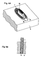
- FIGS 4A and 4B show the initial state, in which the bristle tufts 7 are positioned in the carrier part 8, in the arrangement according to the bristle field 6 to be created, a still non-reshaped bristle tuft 7 being shown according to Figure 4B .
- the ends to be melted of the bristle-tufts 7 are arranged in different planes so that the tuft ends define a three-dimensional arrangement, cf.
- Figure 4a In the embodiment shown, the ends of bristle tufts 7 of a center row 35 are positioned higher than the bristle tufts of rows 36, 37 lying on the outside.
- the required amount of heat is supplied individually to each bristle tuft 7 via variable hot gas input 32 or infrared radiation 33 using a hot-gas device 11 or an infrared-radiation device 34.
- identical amounts of hot gas or infrared radiation can be applied to one or more adjacent bristle tufts 7.
- identical amounts of hot gas 32 or infrared radiation 33 may be applied to rows and/or special arrangements of bristle tufts 7.
- the hot-gas device 11 comprises a multiplicity of nozzles 12, which are positioned with respect to one another in a grid-like arrangement which substantially corresponds to the distribution of the ends of the bristle tufts in the carrier part 8.
- tubular gas outlet channels are provided as the nozzles 12, cf. Figure 5a .
- the nozzles 12 may be supported to be three-dimensionally adjustable; for example, they can be positioned at various heights in the longitudinal direction of the nozzles 12, as shown in Figure 6 meaning that different nozzles 12 may be positioned in different planes with respect to the ends to be heated.
- the outlet openings of the nozzles 12 can be placed in a raised, relief-like pattern that corresponds, in a complementary manner, to the raised, relief-like arrangement of the tuft ends in the carrier part 8, such that the distance between the nozzles 12 and the respective ends of the tufts can be adjusted individually.
- the distance between the nozzles 12 and the respective ends of the tufts can be adjusted individually in all direction in space.
- consistent distances can be set between the nozzles 12 and the ends of the tufts 7 to heat the tufts 7 equally.
- different distances can also be used taking into consideration various parameters, for example different bristle materials, tuft cross-sections and geometries.
- different designs of the thickenings 10 may be desired, which may also entail a different setting of the nozzles 12 to heat the end of the tufts 7 differently.
- the cross-section of the nozzles 12 may be adapted to the cross-section of the respective bristle tufts 7, for example such that thicker nozzles 12 are assigned to thicker bristle tufts 7.
- nozzles 12 may be optionally used that are adjustable in the cross-section thereof. If inclined bristle tufts 7 are used, it may be advantageous to be able to change the adjustment angle of the nozzles 12.
- the hot-gas device 11 may also vary the temperature and the amount or the mass flow of the hot gas flow.
- a temperature-control device and/or regulating device and a mass flow control and/or regulating device may be provided which can be designed in such a way that the temperature of the hot gas flows 32 and/or the air volumes and/or the mass flow exiting from each nozzle 12 can be individually adjusted for each nozzle 12, i.e. independently of each of the other nozzles 12. In this way, the desired amount of heat can be supplied individually to each bristle tuft 7, such that the melting of the ends of the bristles can be controlled in a targeted manner.
- each bristle tuft 7 it would be possible to successively approach each bristle tuft 7 to be melted, using a corresponding nozzle 12.
- all of the bristle tufts 7 can be melted simultaneously using a multiplicity of nozzles 12, thereby achieving short process times.
- a mechanical reshaping of the melted thickenings 10 can be performed.
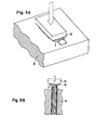
- a punching tool 13 is used which is moved up against the still-soft, malleable thickenings 10, in order to shape said thickenings 10 in the desired manner.
- a flat, disk-shaped thickening 10 is generated in such a way that a flat punching tool 13 is pressed on the front side against the ends of the tufts.
- Differently contoured punching surfaces can also be used to generate differently contoured thickenings.
- the punching tool 13 may not have a continuous flat punching surface, but rather a multiplicity of punching surfaces 14, which may be placed in different planes and/or differently contoured, in order to generate the desired thickening 10 individually for each bristle tuft 7 or for one or more adjacent bristle tufts 7.
- the punching surfaces 14 may be applied to rows and/or special arrangements of bristle tufts 7 in order to generate an identical thickening 10 for several bristle tufts 7.
- the punching surfaces 14 can form a complementary height profile according to the raised, relief-like height profile of the bristle tufts 7 positioned in the carrier part 8, in such a way that the punching surfaces 14 are arranged in various planes in the height profile, as shown in Figure 10 .
- the ends of the bristle tufts 7 can be anchored by over-molding in a bristle carrier 5; i.e., they are cast into the bristle carrier 5 during production thereof.
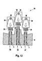
- Figure 12 in another embodiment, shows instead of a hot gas device 11 analogous to Figures 5A, 5B to 11A, 11B , an infrared radiation device 34 having reflectors 38 being positioned at the ends of the bristle tufts 7 protruding from the carrier part 8, to melt the ends of the bristle tufts 7 to form thickenings 10.
- a multiplicity of reflectors 38 having an infrared radiation 33 from an infrared radiation source 39 are directed onto the protruding ends of the bristle tufts 7 in order to apply various degrees of infrared radiation to the various cleaning elements.
- the reflectors 38 in the infrared radiation device 34 are designed to be adjustable with respect to one another, for example spatially adjustable.
- the reflectors 38 may be designed to be positionable at various heights and/or in various planes and/or may be designed to be adjustable with respect to the distances thereof from one another and/or may be supported three-dimensionally adjustable with respect to one another.
- a temperature-control device and/or regulation device may be provided, independently of one another, for controlling and/or regulating the infrared radiation 33 exiting from the reflectors 38.
- the regulation device can be provided also as a control device or a combined control and regulation device, for controlling and/or regulating the infrared radiation 33 exiting from the reflectors 38. Suitable regulation parameters may be the radiation time, radiation intensity and/or radiation frequency.
- the ends of the bristle tufts 7 are mounted by over-molding into the bristle carrier 5 or directly in the brush head 4; i.e., they are cast into the bristle carrier 5 during production thereof.
- the embedment can be done with positive engagement.
- the injection-molding of the bristle carrier 5 to the bristle tufts 7 can generally take place in various ways.
Landscapes
- Engineering & Computer Science (AREA)
- Mechanical Engineering (AREA)
- Physics & Mathematics (AREA)
- Electromagnetism (AREA)
- Health & Medical Sciences (AREA)
- Toxicology (AREA)
- Manufacturing & Machinery (AREA)
- Chemical & Material Sciences (AREA)
- Combustion & Propulsion (AREA)
- Brushes (AREA)
- Moulds For Moulding Plastics Or The Like (AREA)
Abstract
Description
- A brush head, in particular a toothbrush head is described, having a plurality of cleaning elements, in particular bristle tufts, which are anchored by one of their ends in a bristle carrier, and wherein the cleaning elements are molded in blind-hole shaped retaining recesses in a form-closed manner. Further a method and a tool for producing a brush head, in particular a toothbrush head, are disclosed in which cleaning elements, in particular bristle tufts, are fused at one of their ends using heat before these ends are embedded into the bristles carrier, for instance by over-molding with a plastic material.
- Various methods are known in order to fasten the bristle tufts in the bristle carrier of toothbrushes, wherein usually injection-molding from plastic is used. There are known the so-called anchor tufting methods, in which the bristles of a tuft are bent, in the shape of a U, around a retaining web which is then driven into a blind hole. There are also known the so-called hot-tufting methods, in which the bristle tufts are anchored on the bristle carrier by means of a forming technique. Usually, the bristle tufts are melted at their ends to form thickenings and then are over-molded with plastic or cast into the head when the brush head is injection-molded.
- Such hot-tufting methods have various advantages, for example with respect to hygiene, because less bacteria can collect in the anchoring areas, or also with respect to the cross-sectional geometry of the bristle tufts, which can be designed in greater variety than with the anchor tufting methods. But, it is not easy to generate bristle fields with different properties in different areas using the hot-tufting method. In order to optimize the cleaning efficiency of toothbrushes, it may be helpful to provide different cleaning elements or bristle tufts in different sections of the bristle field. It can be also helpful support cleaning elements or bristle tufts in a different manner, for example to support a portion thereof rigidly in a section of hard plastic and another portion thereof flexibly in a section of soft plastic. In addition, it may also be beneficial to melt the ends of differently composed bristle tufts, for example consisting of different bristle material, to different degrees, in order to achieve an optimum anchoring. However, this is difficult using hot-tufting methods which melt the ends of the tufts after the tufts have been configured into a bristle field, because the usually required application of heat to a bristle tuft always also affects adjacent tuft ends.
- A hot-tufting method is known, in which the bristle tufts that are held ready in the form of a bristle field are melted at their ends to such an extent that the melted material of adjacent bristle tufts combines. The resulting flat support structure, which connects the bristle tufts, is intended to achieve an increased pull-out resistance. However, it is difficult in this case to use bristle tufts of differing bristle materials in order to achieve different properties in different bristle field sections, since different types of bristle materials cannot easily be fused together. This becomes even more difficult when not only bristle tufts but also differently designed cleaning elements, such as strips of soft plastic, are to be used and to be combined, for example, with bristle tufts. In addition, the flat support structure on the bottom of the bristle tufts inhibits quick filling of the mold cavities when the bristle carrier is injection-molded.
- Accordingly, there is a need for a toothbrush head and manufacturing method thereof, which allows for design flexibility, material flexibility, and support flexibility.
- According to one aspect a method for producing a brush head, in particular a toothbrush head, is discribed, in which at least two different types of cleaning elements or at least two distinctive cleaning elements of the same type or a combination thereof are embedded at one of their ends at least partially in a bristle carrier, wherein said ends are fused by heat before embedding, characterized in that different amounts of heat are supplied to each of the at least two different types of cleaning elements or the at least two distinctive cleaning elements of the same type or the combination thereof.
- According to another aspect a brush head, in particular a toothbrush head, is described having at least two different types of cleaning elements or at least two distinctive cleaning elements of the same type or a combination thereof being embedded into a brush head, wherein the at least two cleaning elements are fused before embedding using the method described above.
- According to another aspect a device for producing a brush head, in particular a toothbrush head is described in which at least two different types of cleaning elements or at least two distinctive cleaning elements of the same type or a combination thereof are embedded at one of their ends at least partially in a bristle carrier, comprising a hot-gas device for applying hot gas to one end of the at least two different types of cleaning elements or the at least two distinctive cleaning elements of the same type or the combination thereof, wherein the hot-gas device comprises a multiplicity of nozzles for applying varying flows of hot gas or an infrared radiation device for applying infrared radiation to one end of the at least two different types of cleaning elements or the at least two distinctive cleaning elements of the same type or the combination thereof, wherein the infrared radiation device comprises a plurality of reflectors for applying varying degrees of infrared radiation.
-
- Figure 1
- shows a schematic side view of a toothbrush with a bristle field comprising a multiplicity of bristle tufts which are anchored in an injection-molded bristle carrier in a hot-tufting process;
- Figures 2A, 2B
- show a schematic sectional view of a carrier part for retaining the bristle tufts during the production process; insertion of the bristle tufts into the carrier part is shown in
Figure 2A , and the bristle tufts already in place are shown inFigure 2B ; - Figure 3
- shows a schematic sectional view illustrating the melting and thickening of the ends of the bristle tufts prior to the injection process;
- Figure 4A
- shows a schematic, perspective illustration of the bristle tufts situated in the carrier part, which shows the positioning of the bristle tufts according to the subsequent arrangement thereof on the brush head;
- Figure 4B
- shows, in a partial detail view, an enlarged sectional view of a bristle tuft in the carrier part according to
Figure 4A ; - Figure 5A
- shows a schematic, perspective illustration of the melting, through application of hot gas to the ends of the bristle tufts to be embedded, wherein the hot-gas tool is shown in a working position;
- Figure 5B
- shows, in a partial detail view, an enlarged sectional view of the bristle tuft in the carrier part according to
Figure 5A ; - Figure 6
- shows a schematic sectional view of the hot-gas device and the nozzles thereof at the bristle-tuft ends protruding out of the carrier part prior to the melting process;
- Figure 7
- shows a schematic sectional view of the hot-gas device, similar to
Figure 6 , the bristle tufts being shown after the melting and formation of an end-side thickening; - Figure 8A
- shows a schematic, perspective illustration of the bristle tufts situated in the carrier part with a melted end section after heat treatment by means of hot gas;
- Figure 8B
- shows a partial view of an enlarged sectional view of a bristle tuft with a melted end section according to
Figure 8A ; - Figure 9A
- shows a schematic, perspective illustration of the mechanical reshaping by means of a punching tool of the melted end sections of the bristle tufts situated in the carrier part;
- Figure 9B
- shows a partial view, in an enlarged illustration, of a bristle tuft and the reshaping of the melted end section thereof by means of a section of the punching tool;
- Figure 10
- shows a schematic sectional view through a punching tool for mechanical reshaping of the melted end sections of the bristle tufts, wherein the punching tool has different three-dimensional punching sections which can be positioned;
- Figure 11A
- shows a schematic, perspective illustration of the finished reshaped end sections of the bristle tufts situated in the carrier part;
- Figure 11B
- shows a partial view, in an enlarged sectional view, of an individual finished reshaped bristle tuft;
- Figure 12
- shows a schematic sectional view, similar to that in
Figure 6 , but with an infrared-radiation device, instead of a hot-gas device, and the reflectors of the infrared-radiation device at the bristle-tuft ends protruding from the carrier part prior to the melting process; - The brush head and the method for the production thereof as disclosed herein, as well as an improved tool for the production of said brush head allow design flexibility, for example, in the positioning of cleaning elements and allows providing of different types of cleaning elements, including cleaning elements made from differing materials. An improved brush head may comprise, for example, a compact form and is efficient to produce, despite the complex design of the bristle field thereof, having, for example, differently designed cleaning elements.
- A method for producing a brush head, in particular a toothbrush head is shown, wherein different cleaning elements, in particular bristle tufts, are fused and over-molded at one of their ends using a plastic material. "Different cleaning elements" as used herein shall be understood as two different types of cleaning elements or two distinctive cleaning elements of the same type or a combination thereof. "Different types of cleaning elements" as used herein shall be understood as cleaning elements differing at least in the material they are made from. An example for different types of cleaning elements may be bristles made of different materials or bristles and elastomeric elements. "Distinctive cleaning elements of the same type" as used herein shall be understood as cleaning elements which are made of the same material, but which are distinguishable from each other in at least one other property. Examples for these other properties in which the distinctive cleaning elements of the same type may differ are e.g. size, composition, form, outer shape, surface appearance or a combination thereof. An example for distinctive cleaning elements of the same type may be bristle tufts having different tuft diameters or having different tuft geometries, or bristles being tapered or crimpled compared to unmodified bristles.
- The cleaning elements may be held by at least one carrier part which has hole-shaped retaining recesses, in which the cleaning elements may be held during the process of fusing and over-molding. The position of the cleaning elements in the carrier part corresponds to the desired relative arrangement thereof with respect to one another on the brush head. Additionally, said carrier part may form a wall of the mold cavities, in which the ends of the cleaning elements extending out from the carrier part can be over-molded in a multicomponent process. Owing to the use of the carrier part as part of the injection mold, the positioning of the ends of the cleaning elements to be over-molded as well as the opening and closing of the injection mold can be executed very simply and efficiently. The side of the carrier part facing the ends to be over-molded may form a negative mold for the cleaning-element-side or bristle-side surface of the bristle carrier of the brush head.
- The cleaning elements can be transported from a first injection-molding station in which at least one part of a bristle carrier and/or a brush head is injection-molded to a second injection-molding station, in which at least another part of a bristle carrier and/or a brush head is injection-molded. Further steps of transportation to additional injection-molding stations in which additional parts of the bristle-carrier and/or the brush head can be injection-molded are also applicable to the method as described herein. Additionally, the cleaning elements may be located in the at least one carrier part during transportation. Thus, the aforementioned carrier part, in which the cleaning elements are arranged, may also used for handling and/or transporting of the cleaning elements in or between the different process steps. For example, the cleaning elements, arranged in the carrier part, may be positioned in various injection molds to mold different sections of the brush head. In addition, the cleaning elements may be arranged in the carrier part for the upstream process step, such as, for example, the thermal treatment for melting the ends of the cleaning elements to form thickenings. The carrier part may be also used as a part of the mold cavity for one or more of said injection-molding stations.
- The thickenings at the cast ends of the cleaning elements are formed in order to increase the pull-out resistance of the cleaning elements from the bristle carrier. Said thickenings may be produced by thermal melting of the ends. The ends which are melted are the ends to be over-molded, i.e. said ends are not the ends for cleaning the teeth. A targeted energy flow is applied to the cleaning elements at their ends to be over-molded, either individually or in groups in each case, and reshaped into a thickening. Generally, this can be carried out by means of various types of energy flows in the form of mass flows and/or radiation. For example the ends to be thickened may have a targeted flow of hot gas applied thereto individually or in groups, in order to be melted thermally. The corresponding flows of hot gas may be controlled individually, that is to say independently of one another, for at least two cleaning elements, in order to achieve an individual melting and/or reshaping of the ends of the cleaning elements. Thereby, varying flows of hot gas can be generated with respect to temperature, gas volume, and/or flow geometry, so as to be applied differently to the different cleaning elements as a result. This makes it possible to measure out to each cleaning element precisely the amount of heat input that is required in order to produce the desired reshaping.
- The individually controllable flows of hot gas may be created using separate nozzles that are directed toward the ends of the cleaning elements to which the hot gas flows are to be applied. By means of the aforementioned carrier part it is possible to hold said cleaning elements in a predefined arrangement corresponding to the desired distribution thereof on the brush head. Thus, the cleaning elements can have varying flows of hot gas applied to individually or optionally in groups while they are being held by the carrier part in the manner in which they are intended to be cast in the brush head. This reduces additional handling measures, such as for example grip changes or reinsertion of the cleaning elements into different carrier parts. Despite the optionally very dense arrangement, the ends of the cleaning elements can have heat applied thereto in the desired manner independently of one another.
- The nozzles in this case are designed such that they can be moved into various positions relative to one another. For example the nozzles are designed to be adjustable in a manner such that the nozzles can be positioned in a grid pattern that corresponds to the grid pattern of the arrangement of the cleaning elements. The nozzles can be designed adjustable with respect to their geometry, such as, for example, the nozzle cross-section or the opening angle, in order, for example, to be able to apply varying flows of hot gas to cleaning elements having cross-sections of varying thicknesses.
- The nozzles may be controlled with respect to their position and/or geometry, such as the opening angle, according to at least one property of the respective cleaning elements. Meaning in one aspect, the nozzles can be adjusted three-dimensionally according to a property of the respective cleaning elements. For example the nozzles may be adjusted such that the nozzles can be positioned in various planes according to the height grid and/or height relief of the ends of the cleaning elements. I.e. the nozzles can be positioned in the aforementioned manner at differing heights with respect to one another, in order to set a uniform distance from the ends of the cleaning elements, even when similar or identical cleaning elements are positioned in different planes. Other properties to which the position of the nozzles may be adjusted are the softening temperature and/or a cross-sectional geometry of the cleaning elements.
- The hot-gas device may have a temperature control that enables the flows of hot gas exiting from the various nozzles to be controlled at differently hot temperatures in order to be able to adjust the application of heat individually to the respective cleaning elements. The temperature of the flows of hot gas in this case can be adjusted individually for each nozzle according to different parameters, for example according to a material of the respective cleaning elements, the softening temperature and/or according to the cross-sectional surface of the respective cleaning element. For example, a thicker cleaning element and/or one having a higher softening temperature can be given a hotter flow of gas than a thinner cleaning element and/or one having a lower softening temperature.
- The hot-gas device may have an air volume control that can individually control the flow of air exiting from the various nozzles, such that, for example, a stronger flow of air exits from a first nozzle than from a second nozzle. The flows of air can be controlled automatically or semi-automatically according to at least one parameter, for example the softening temperature and/or the cross-sectional surface of a respective cleaning element. Alternatively or in addition, individual set nozzle geometry can be considered, for example in such a way that a greater air flow is set when the nozzle is set to a larger expansion angle. Various other parameters may also be considered.
- In addition or alternatively, the ends to be thickened may have a targeted flow of infrared radiation applied thereto, in order to be melted thermally. The corresponding amount of infrared radiation may be controlled individually or in groups, e.g. independently of one another, for at least two cleaning elements, in order to achieve an individual melting and/or reshaping of the ends of the cleaning elements. Thereby, varying amounts of infrared radiation can be generated with respect to radiation time, radiation intensity and/or radiation frequency so as to be applied differently to the different cleaning elements as a result. This makes it possible to measure out to each cleaning element precisely the amount of heat input that is required in order to produce the desired reshaping.
- The individually controllable amounts of infrared radiation may be created using separate reflectors that are directed toward the ends of the cleaning elements to which the infrared radiation is to be applied. By means of the aforementioned carrier part it is possible to hold said cleaning elements in a predefined arrangement corresponding to the desired distribution thereof on the brush head. Thus, the cleaning elements can have varying amounts of infrared radiation applied to individually or optionally in groups while they are being held by the carrier part in the manner in which they are intended to be cast in the brush head. This reduces additional handling measures, such as for example grip changes or reinsertion of the cleaning elements into different carrier parts. Despite the optionally very dense arrangement, the ends of the cleaning elements can have heat applied thereto in the desired manner independently of one another.
- The reflectors may be designed such that they can be moved into various positions relative to one another. For example the reflectors may be designed to be adjustable in a manner such that the reflectors can be positioned in a grid pattern that corresponds to the grid pattern of the arrangement of the cleaning elements. Alternatively or in addition, the reflectors can be designed adjustable with respect to their geometry. For example, parabolic and/or elliptic reflectors can be used having various aperture and/or diameters, in order, for example, to be able to apply varying amounts of infrared radiation to cleaning elements having cross-sections of varying thicknesses.
- The reflectors may be controlled with respect to their position and/or geometry according to at least one property of the respective cleaning elements. Meaning in one aspect, the reflectors can be adjusted three-dimensionally according to a property of the respective cleaning elements. For example the reflectors may be adjusted such that the reflectors can be positioned in various planes according to the height grid and/or height relief of the ends of the cleaning elements. I.e. the reflectors can be positioned in the aforementioned manner at differing heights with respect to one another, in order to set a uniform distance from the ends of the cleaning elements, even when similar or identical cleaning elements are positioned in different planes. Other properties to which the position and/or geometry of the reflectors may be adjusted are the softening temperature and/or a cross-sectional geometry of the cleaning elements.
- Alternatively or in addition, the infrared-radiation device may have a frequency and/or intensity control that enables the nature and/or amounts of infrared radiation exiting from the various reflectors to be controlled in order to be able to adjust the application of heat individually to the respective cleaning elements. The frequency and/or intensity of the infrared radiation in this case can be adjusted individually for each reflector according to different parameters, for example according to a material of the respective cleaning elements and/or according to the cross-sectional surface of the respective cleaning element. For example, a thicker cleaning element and/or one having a higher softening temperature can be given more infrared radiation being more energetic than a thinner cleaning element and/or one having a lower softening temperature.
- The reshaping of the ends of the cleaning elements can be carried out solely by means of the application of a targeted energy flow, for example hot gas or infrared radiation, wherein, the effects of gravity can be utilized. Thereby, the cleaning elements with their ends to be melted are positioned pointing upward, such that a melted end section is pressed downward, thus resulting in a mushroom-shaped or drop-shaped thickening.
- Alternatively or in addition, a punching tool can be used to create the thickening. Said punching tool may be driven against the melted ends of the cleaning elements in order to reshape the heated ends accordingly. The punching tool can have various punching surfaces, the shapes of which are adapted in each case to one cleaning element or group of cleaning elements, and which only reshape individually the one cleaning element or one group of cleaning elements, respectively. This makes it possible for a plurality of cleaning elements to be individually reshaped by means of one punching tool having various punching surfaces. Various punching surfaces of the punching tool may be adjustable with respect to one another, in particular to be capable of being positioned in various planes with respect to one another. This makes it possible to create a punching tool pad of different punching surfaces which are positioned raised in relief-like manner at various heights, in order to enable reshaping of the ends of the cleaning elements, which ends are positioned at different heights.
- In addition or alternatively a device is provided for carrying out the method as described above. Said device comprises at least a positioning unit for positioning successively or simultaneously at least two different types of cleaning elements or at least two distinctive cleaning elements of the same type or a combination thereof in at least two different mold cavities, an injection unit capable of injecting at least two different materials in the at least two different mold cavities and a heating unit for heating one end of the at least two different types of cleaning elements or at least two distinctive cleaning elements of the same type or a combination thereof. The end to be heated is the end to be over-molded. The heating unit may comprise a hot-gas device for applying hot gas or an infrared radiation device for applying infrared radiation to one end of the at least two different types of cleaning elements or at least two distinctive cleaning elements of the same type or a combination thereof. In addition or alternatively a brush head, for example a toothbrush head is disclosed having bristle tufts comprising at least two different types of cleaning elements or at least two distinctive cleaning elements of the same type or a combination thereof being cast as described above.
- These and other features, which can form the subject matter of the invention irrespective of how they are summarized in the claims, optionally in sub-combination, individually or in combination with one another, will become apparent not only from the claims but also from the following description and the drawings, with the aid of which example embodiments are explained below.
- The toothbrush 1 shown in
Figure 1 comprises a shaft-like handle 2, which is connected to a brush head 4 via aneck piece 3. The brush head 4 in this case comprises abristle carrier 5 joined to theaforementioned neck piece 3 which supports a bristle field 6, which comprises a multiplicity ofbristle tufts 7. Instead of thebristle tufts 7, or in combination with thebristle tufts 7, other cleaning elements could be provided, for example in the form of elastomer strips, sponge elements, or other tooth cleaning elements. In the embodiment shown, the toothbrush 1 is designed as a manual toothbrush; however, a motor-driven toothbrush could also have a correspondingly designed brush head. - The
bristle tufts 7 can usually comprise a multiplicity of bristles or filaments that are combined to form atuft 7. The bristles or filaments in this case are cut to the desired lengths, the free ends of the tufts optionally being tapered or rounded off as desired, which can occur on the finished toothbrush 1 or can also be effected before thebristle tufts 7 are anchored on the brush head 4. -
Figures 2-12 show the fusing of thebristle tufts 7 before they are fastenedin thebristle carrier 5. According toFigure 2A , preconfigured, for example cut-to-length, bristletufts 7 are first placed into acarrier part 8 which may form a part of the injection mold for injection molding thebristle carrier 5 or the brush head 4 later on. As shown inFigure 2A , thecarrier part 8 comprises a multiplicity of receptacle recesses 9, which are designed in the form of a through-hole or a blind-hole and which accommodate thecorresponding bristle tufts 7 with an accurately fitting. The receptacle recesses 9 may be arranged in a grid pattern that corresponds to the desired positioning of thebristle tufts 7 on the brush head 4. As shown inFigure 2B , thebristle tufts 7 with their ends to be anchored protrude by a certain length beyond thecarrier part 8, such that the aforementioned ends of thebristle tufts 7 can be positioned in a mold cavity of an injection mold, in order to be over-molded with plastic therein. - In order to achieve increased resistance of the
bristle tufts 7 against being pulled from thebristle carrier 5, the ends of the bristle-tuft 7 to be embedded are first reshaped through application of heat energy-for example usinghot gas 32 or infrared radiation 33-in order to formthickenings 10, as shown inFigure 3 . - In order to produce the
thickenings 10, the ends of thebristle tufts 7 protruding from thecarrier part 8 are first melted through application ofhot gas 32 orinfrared radiation 33.Figures 4A and 4B show the initial state, in which thebristle tufts 7 are positioned in thecarrier part 8, in the arrangement according to the bristle field 6 to be created, a still non-reshaped bristletuft 7 being shown according toFigure 4B . According toFigure 4A , the ends to be melted of the bristle-tufts 7 are arranged in different planes so that the tuft ends define a three-dimensional arrangement, cf.Figure 4a . In the embodiment shown, the ends ofbristle tufts 7 of acenter row 35 are positioned higher than the bristle tufts ofrows - In order to still be able to achieve an individually adapted melting despite the three-dimensional distribution and optional varying cross-sectional surface of the
individual bristle tufts 7, the required amount of heat is supplied individually to each bristletuft 7 via variablehot gas input 32 orinfrared radiation 33 using a hot-gas device 11 or an infrared-radiation device 34. Alternatively or in addition identical amounts of hot gas or infrared radiation can be applied to one or moreadjacent bristle tufts 7. Alternatively or in addition, identical amounts ofhot gas 32 orinfrared radiation 33 may be applied to rows and/or special arrangements ofbristle tufts 7. - As shown in
Figures 5A, 5B , and6 , the hot-gas device 11 comprises a multiplicity ofnozzles 12, which are positioned with respect to one another in a grid-like arrangement which substantially corresponds to the distribution of the ends of the bristle tufts in thecarrier part 8. In the embodiment shown, tubular gas outlet channels are provided as thenozzles 12, cf.Figure 5a . - The
nozzles 12 may be supported to be three-dimensionally adjustable; for example, they can be positioned at various heights in the longitudinal direction of thenozzles 12, as shown inFigure 6 meaning thatdifferent nozzles 12 may be positioned in different planes with respect to the ends to be heated. The outlet openings of thenozzles 12 can be placed in a raised, relief-like pattern that corresponds, in a complementary manner, to the raised, relief-like arrangement of the tuft ends in thecarrier part 8, such that the distance between thenozzles 12 and the respective ends of the tufts can be adjusted individually. The distance between thenozzles 12 and the respective ends of the tufts can be adjusted individually in all direction in space. - In the embodiment shown in
Figure 6 , consistent distances can be set between thenozzles 12 and the ends of thetufts 7 to heat thetufts 7 equally. However, different distances can also be used taking into consideration various parameters, for example different bristle materials, tuft cross-sections and geometries. Alternatively or in addition, different designs of thethickenings 10 may be desired, which may also entail a different setting of thenozzles 12 to heat the end of thetufts 7 differently. - The cross-section of the
nozzles 12 may be adapted to the cross-section of therespective bristle tufts 7, for example such thatthicker nozzles 12 are assigned tothicker bristle tufts 7. In order to achieve greater variability in this case, nozzles 12 may be optionally used that are adjustable in the cross-section thereof. If inclined bristletufts 7 are used, it may be advantageous to be able to change the adjustment angle of thenozzles 12. - Alternatively or in addition to the adjustability of the
nozzles 12, the hot-gas device 11 may also vary the temperature and the amount or the mass flow of the hot gas flow. To this end, a temperature-control device and/or regulating device and a mass flow control and/or regulating device may be provided which can be designed in such a way that the temperature of the hot gas flows 32 and/or the air volumes and/or the mass flow exiting from eachnozzle 12 can be individually adjusted for eachnozzle 12, i.e. independently of each of theother nozzles 12. In this way, the desired amount of heat can be supplied individually to each bristletuft 7, such that the melting of the ends of the bristles can be controlled in a targeted manner. - As a comparison of
Figures 6 and 7 shows, the ends of thebristle tufts 7 are melted by the application ofhot gas 32 coming from thenozzles 12 to the extent that drop-shapedthickenings 10 form due to the effects of gravity and surface tension. Thebristle tufts 7 are arranged in an essentially vertical orientation with the ends to be melted pointing upwards when the hot gas is applied, cf.Figure 6 and 7 . Bristle tufts can be angled as discussed above. - Generally, it would be possible to successively approach each bristle
tuft 7 to be melted, using a correspondingnozzle 12. However, all of thebristle tufts 7 can be melted simultaneously using a multiplicity ofnozzles 12, thereby achieving short process times. Anyway, it is also conceivable for only a part of thebristle tuft 7 to be melted. According toFigures 8A and 8B , it is, possible to soften all of thebristle tufts 7 in the bristle field by melting, in order to achieve a corresponding increase in the pull-out resistance of all of the bristle tufts in a plastic material. - As shown in
Figures 9-11 , a mechanical reshaping of the meltedthickenings 10 can be performed. To this end, apunching tool 13 is used which is moved up against the still-soft,malleable thickenings 10, in order to shape saidthickenings 10 in the desired manner. As shown in the figures, a flat, disk-shapedthickening 10 is generated in such a way that aflat punching tool 13 is pressed on the front side against the ends of the tufts. Differently contoured punching surfaces can also be used to generate differently contoured thickenings. - The
punching tool 13 may not have a continuous flat punching surface, but rather a multiplicity of punchingsurfaces 14, which may be placed in different planes and/or differently contoured, in order to generate the desired thickening 10 individually for each bristletuft 7 or for one or moreadjacent bristle tufts 7. For example, the punching surfaces 14 may be applied to rows and/or special arrangements ofbristle tufts 7 in order to generate anidentical thickening 10 forseveral bristle tufts 7. In particular, the punching surfaces 14 can form a complementary height profile according to the raised, relief-like height profile of thebristle tufts 7 positioned in thecarrier part 8, in such a way that the punching surfaces 14 are arranged in various planes in the height profile, as shown inFigure 10 . - Owing to a parallel reshaping process of all melted ends of the
bristle tufts 7, same can be shaped in the desired way in a time-parallel manner, as shown inFigures 11A and 11B . In particular, thin, flat, and/or plate-shapedthickenings 10 can be created, even when the ends of thebristle tufts 7 are positioned in different planes and/or provided with different geometries and/or consist of various materials. - After forming the
thickenings 10 by means of hot gas flows 32, the ends of thebristle tufts 7 can be anchored by over-molding in abristle carrier 5; i.e., they are cast into thebristle carrier 5 during production thereof. -
Figure 12 , in another embodiment, shows instead of ahot gas device 11 analogous toFigures 5A, 5B to11A, 11B , an infrared radiation device 34 havingreflectors 38 being positioned at the ends of thebristle tufts 7 protruding from thecarrier part 8, to melt the ends of thebristle tufts 7 to formthickenings 10. A multiplicity ofreflectors 38 having aninfrared radiation 33 from aninfrared radiation source 39 are directed onto the protruding ends of thebristle tufts 7 in order to apply various degrees of infrared radiation to the various cleaning elements. - The
reflectors 38 in the infrared radiation device 34 are designed to be adjustable with respect to one another, for example spatially adjustable. For example, thereflectors 38 may be designed to be positionable at various heights and/or in various planes and/or may be designed to be adjustable with respect to the distances thereof from one another and/or may be supported three-dimensionally adjustable with respect to one another. A temperature-control device and/or regulation device may be provided, independently of one another, for controlling and/or regulating theinfrared radiation 33 exiting from thereflectors 38. The regulation device can be provided also as a control device or a combined control and regulation device, for controlling and/or regulating theinfrared radiation 33 exiting from thereflectors 38. Suitable regulation parameters may be the radiation time, radiation intensity and/or radiation frequency. - After formation of the
thickenings 10 using hot gas flows 32 orinfrared radiation 33, the ends of thebristle tufts 7 are mounted by over-molding into thebristle carrier 5 or directly in the brush head 4; i.e., they are cast into thebristle carrier 5 during production thereof. The embedment can be done with positive engagement. The injection-molding of thebristle carrier 5 to thebristle tufts 7 can generally take place in various ways. - The dimensions and values disclosed herein are not to be understood as being strictly limited to the exact numerical values recited. Instead, unless otherwise specified, each such dimension is intended to mean both the recited value and a functionally equivalent range surrounding that value. For example, a dimension disclosed as "40 mm" is intended to mean "about 40 mm."
Claims (15)
- A method for producing a brush head (4), in particular a toothbrush head, in which at least two different types of cleaning elements or at least two distinctive cleaning elements of the same type or a combination thereof are embedded at one of their ends at least partially in a bristle carrier (5), wherein said ends are fused by heat before embedding, characterized in that different amounts of heat are supplied to each of the at least two different types of cleaning elements or the at least two distinctive cleaning elements of the same type or the combination thereof.
- The method according to the preceding claim, wherein the ends to be embedded are fused by subjecting them, either individually or in groups, to a targeted energy flow, in particular to a targeted flow of hot gas (32) or to targeted infrared radiation (33).
- The method according to the preceding claim, wherein the targeted hot gas flow (32) that is directed towards the end of the cleaning elements is created using separate nozzles (12) or wherein the targeted infrared radiation (33) that is directed towards the end of the cleaning elements is created using separate reflectors (38).
- The method according to anyone of the preceding claims, wherein the at least two different types of cleaning elements or the at least two distinctive cleaning elements of the same type or the combination thereof are held by a carrier part (8) in a predefined arrangement according to their desired distribution on the brush head (4).
- The method according to anyone of the preceding claims, wherein the different amounts of heat that are supplied to each of the at least two different types of cleaning elements or the at least two distinctive cleaning elements of the same type or the combination thereof depend on at least one property in which the at least two different types of cleaning elements or the at least two distinctive cleaning elements of the same type or the combination thereof are distinguishable from each other.
- The method according to the preceding claim, wherein the at least one property in which the at least two different types of cleaning elements or the at least two distinctive cleaning elements of the same type or the combination thereof are distinguishable is the material, the colour, the thickness, the outer shape, the composition and/or the distance to the soure of the heat.
- The method according to anyone of the preceding claims, wherein after the ends of the at least two different types of cleaning elements or the at least two distinctive cleaning elements of the same type or the combination thereof have been heated, a punching tool (13) is moved against the softened ends for reshaping them.
- The method according to the preceding claim, wherein, the punching tool (13) has a flat or a structured surface.
- A brush head, in particular a toothbrush head, having at least two different types of cleaning elements or at least two distinctive cleaning elements of the same type or a combination thereof being embedded into a brush head (4), wherein the at least two cleaning elements are fused before embedding using the method according to anyone of claims 1 to 8.
- The brush head according to claim 9, wherein the embedded ends of the at least two different types of cleaning elements or the at least two distinctive cleaning elements of the same type or the combination thereof are arranged in a common anchoring plane or in different anchoring planes being arranged above each other.
- The brush head according to claims 9 or 10, wherein the at least two different types of cleaning elements or the at least two distinctive cleaning elements of the same type or the combination thereof comprise thickenings (10) at the ends to be embedded after fusing that are different from one another.
- A device for producing a brush head (4), in particular a toothbrush head in which at least two different types of cleaning elements or at least two distinctive cleaning elements of the same type or a combination thereof are embedded at one of their ends at least partially in a bristle carrier (5), comprisinga) a hot-gas device (11) for applying hot gas (32) to one end of the at least two different types of cleaning elements or the at least two distinctive cleaning elements of the same type or the combination thereof, wherein the hot-gas device (11) comprises a multiplicity of nozzles (12) for applying varying flows of hot gas (32) orb) an infrared radiation device (34) for applying infrared radiation (33) to one end of the at least two different types of cleaning elements or the at least two distinctive cleaning elements of the same type or the combination thereof, wherein the infrared radiation device (34) comprises a plurality of reflectors (38) for applying varying degrees of infrared radiation (33).
- The device according to Claim 12, wherein the nozzles (12) or the reflectors (38) are designed to be adjustable with respect to one another.
- The device according to claims 12 or 13, wherein the device comprises a temperature-control and/or regulation device for controlling and/or regulating the hot gas flows (32) exiting from the nozzles (12) or the infrared radiation (33) existing from a infrared radiation source (39), independently of one another.
- The device according to anyone of claims 12 to 14, wherein the device comprises a carrier part (8) for holding the free ends of the at least two different types of cleaning elements or the at least two distinctive cleaning elements of the same type or the combination thereof which are not intended to be embedded.
Priority Applications (1)
| Application Number | Priority Date | Filing Date | Title |
|---|---|---|---|
| EP12004431.8A EP2534973B1 (en) | 2011-06-15 | 2012-06-12 | Method and tool for producing a brush head |
Applications Claiming Priority (2)
| Application Number | Priority Date | Filing Date | Title |
|---|---|---|---|
| EP11004870 | 2011-06-15 | ||
| EP12004431.8A EP2534973B1 (en) | 2011-06-15 | 2012-06-12 | Method and tool for producing a brush head |
Publications (3)
| Publication Number | Publication Date |
|---|---|
| EP2534973A2 true EP2534973A2 (en) | 2012-12-19 |
| EP2534973A3 EP2534973A3 (en) | 2014-01-29 |
| EP2534973B1 EP2534973B1 (en) | 2015-04-08 |
Family
ID=44863322
Family Applications (2)
| Application Number | Title | Priority Date | Filing Date |
|---|---|---|---|
| EP12004431.8A Active EP2534973B1 (en) | 2011-06-15 | 2012-06-12 | Method and tool for producing a brush head |
| EP20120004432 Active EP2534974B1 (en) | 2011-06-15 | 2012-06-12 | Method for producing a brush head |
Family Applications After (1)
| Application Number | Title | Priority Date | Filing Date |
|---|---|---|---|
| EP20120004432 Active EP2534974B1 (en) | 2011-06-15 | 2012-06-12 | Method for producing a brush head |
Country Status (3)
| Country | Link |
|---|---|
| US (3) | US20120317738A1 (en) |
| EP (2) | EP2534973B1 (en) |
| CN (2) | CN102824027B (en) |
Cited By (3)
| Publication number | Priority date | Publication date | Assignee | Title |
|---|---|---|---|---|
| EP2886009A1 (en) | 2013-12-18 | 2015-06-24 | The Gillette Company | Device for fusing the ends of thermoplastic filaments |
| WO2019081146A1 (en) * | 2017-10-24 | 2019-05-02 | Koninklijke Philips N.V. | Brush head manufacturing method and device |
| RU2786984C2 (en) * | 2017-10-24 | 2022-12-27 | Конинклейке Филипс Н.В. | Method for manufacture of brush head |
Families Citing this family (28)
| Publication number | Priority date | Publication date | Assignee | Title |
|---|---|---|---|---|
| US6564416B1 (en) | 2000-05-22 | 2003-05-20 | Gillette Canada Company | Toothbrush |
| US9848959B2 (en) | 2007-07-05 | 2017-12-26 | Orthoaccel Technologies, Inc. | Massaging or brushing bite plates |
| DK2816930T3 (en) * | 2012-02-24 | 2020-05-25 | Vikan As | Method of making a hygienic brush head |
| EP2676572B1 (en) * | 2012-06-19 | 2018-07-04 | Braun GmbH | Carrier for cleaning elements and method for using such carriers in the production of toothbrush heads |
| EP2886289B1 (en) * | 2013-12-19 | 2016-08-03 | The Gillette Company | Method to manufacture an injection molded component and injection molded component |
| JP6662786B2 (en) * | 2014-03-25 | 2020-03-11 | コーニンクレッカ フィリップス エヌ ヴェKoninklijke Philips N.V. | Brush head manufacturing method |
| RU2707694C2 (en) | 2015-05-14 | 2019-11-28 | Конинклейке Филипс Н.В. | Cleaning head unit |
| CN107624043B (en) | 2015-05-14 | 2020-07-10 | 皇家飞利浦有限公司 | Brush head assembly and method of manufacture |
| US10750847B2 (en) | 2015-05-14 | 2020-08-25 | Koninklijke Philips N.V. | Brush head arrangements |
| EP3294088B1 (en) | 2015-05-14 | 2022-07-06 | Koninklijke Philips N.V. | Brush head assembly and methods of manufacture |
| DE102016107759B4 (en) * | 2015-07-13 | 2024-11-14 | Gb Boucherie Nv | Method and device for producing a brush |
| JP6523900B2 (en) * | 2015-09-28 | 2019-06-05 | 三菱鉛筆株式会社 | Brush and method of manufacturing brush |
| BE1023055B1 (en) * | 2015-10-26 | 2016-11-16 | Bart Gerard Boucherie | Apparatus and method for producing bristle pads for brushes |
| KR102678545B1 (en) * | 2016-04-26 | 2024-06-25 | 지비 부쉐리 엔브이 | Brush manufacturing method and device |
| EP3262974B1 (en) | 2016-06-27 | 2024-06-12 | The Procter & Gamble Company | Method for producing toothbrush heads comprising a two-component-cleaning element |
| EP3262975B1 (en) | 2016-06-28 | 2019-02-20 | The Procter and Gamble Company | Method of making brush |
| DE102017106531A1 (en) * | 2017-03-27 | 2018-09-27 | Gb Boucherie Nv | Method and device as well as injection mold half part for making a brush |
| KR102605229B1 (en) | 2017-07-12 | 2023-11-22 | 코닌클리케 필립스 엔.브이. | Stamped brush heads and brush head stamping manufacturing methods |
| EP3461367B1 (en) | 2017-09-28 | 2020-04-22 | The Procter & Gamble Company | Method of making a unitary brush head and unitary toothbrush head |
| EP3723547A1 (en) * | 2017-12-12 | 2020-10-21 | Koninklijke Philips N.V. | Brush head assembly and methods of manufacture |
| EP3753449A1 (en) | 2019-06-21 | 2020-12-23 | The Procter & Gamble Company | Hole perforation plate for manufacturing of a toothbrush head and part thereof |
| EP3753448B1 (en) | 2019-06-21 | 2025-12-10 | The Procter & Gamble Company | Method for producing a toothbrush head |
| EP3753447B1 (en) * | 2019-06-21 | 2025-12-10 | The Procter & Gamble Company | Method for producing a toothbrush head or a part thereof |
| EP3753446B1 (en) | 2019-06-21 | 2025-10-22 | The Procter & Gamble Company | Cleaning element carrier and toothbrush head comprising it |
| EP3753445B1 (en) * | 2019-06-21 | 2025-12-10 | The Procter & Gamble Company | Tootbrush head and part thereof |
| US11160361B2 (en) | 2019-06-28 | 2021-11-02 | Koninklijke Philips N.V. | Brush head assembly |
| CN113796643A (en) * | 2021-08-17 | 2021-12-17 | 安徽友川刷业有限公司 | Fixing structure capable of disassembling bristle bundle and brush base and processing technology of bristle bundle |
| EP4154761B1 (en) | 2021-09-27 | 2025-01-15 | Braun GmbH | Head for a personal care device and method of making thereof |
Family Cites Families (29)
| Publication number | Priority date | Publication date | Assignee | Title |
|---|---|---|---|---|
| DE845933C (en) | 1949-07-28 | 1953-06-11 | Maximilian Schiffer | Method and machine for producing brushes, in particular toothbrushes |
| US4635313A (en) * | 1983-11-16 | 1987-01-13 | North American Philips Corporation | Brush with self retaining bristles |
| DE3484093D1 (en) * | 1983-11-16 | 1991-03-14 | Philips Corp | METHOD FOR THE PRODUCTION OF BRUSHES WITH SELF-FASTENING OF THE BRUSHES AND BRUSHES PRODUCED BY THIS METHOD. |
| DE3511528C1 (en) * | 1985-03-29 | 1991-01-03 | Coronet - Werke Heinrich Schlerf Gmbh, 6948 Wald-Michelbach | Process for the production of bristle goods |
| CN1027706C (en) * | 1990-09-27 | 1995-02-22 | 浙江大学 | Laser treatment method for tooth-brush and brush |
| JP2506002B2 (en) * | 1991-07-18 | 1996-06-12 | 花王株式会社 | Rod-shaped resin tip processing apparatus and method |
| GB2288140A (en) * | 1994-04-07 | 1995-10-11 | Boucherie Nv G B | A method of injection molding of brushes |
| GB2288564B (en) | 1994-04-19 | 1998-09-23 | Boucherie Nv G B | A molding machine for injection molding of tooth brushes |
| DE4415886A1 (en) * | 1994-05-05 | 1995-11-09 | Coronet Werke Gmbh | Process for the production of bristle goods by injection molding |
| DE19538621A1 (en) * | 1995-10-17 | 1997-04-24 | Zahoransky Anton Gmbh & Co | Brush making method, especially toothbrush |
| JPH1042954A (en) * | 1996-08-08 | 1998-02-17 | Lion Corp | Bristle bundle melting method |
| DE19743556A1 (en) * | 1997-10-01 | 1999-04-08 | Schiffer Fa M & C | Method and device for producing a toothbrush |
| DE19853030A1 (en) * | 1998-11-18 | 2000-05-25 | Coronet Werke Gmbh | Process for the production of bristle goods and device for carrying out the process |
| JP2000287755A (en) * | 1999-04-09 | 2000-10-17 | Lion Corp | Method of manufacturing brush products |
| DE59908270D1 (en) * | 1999-06-02 | 2004-02-12 | Schiffer Fa M & C | METHOD AND DEVICE FOR PRODUCING BRUSHES |
| DE19932377A1 (en) | 1999-07-13 | 2001-02-08 | Coronet Werke Gmbh | Method and device for the production of brushes and brushes produced thereafter |
| DE19937481A1 (en) * | 1999-08-07 | 2001-02-08 | Coronet Werke Gmbh | Brushes, especially toothbrushes |
| JP2003061753A (en) * | 2001-08-24 | 2003-03-04 | Kao Corp | Brush manufacturing method |
| CN1212089C (en) * | 2002-02-25 | 2005-07-27 | 花王株式会社 | How to make brushes |
| EP2510830B1 (en) * | 2002-08-09 | 2013-12-25 | Colgate-Palmolive Company | Method of forming a toothbrush |
| DE10259723A1 (en) * | 2002-12-19 | 2004-07-01 | Trisa Holding Ag | Toothbrush and process for making it |
| DE20303934U1 (en) | 2003-03-12 | 2004-07-22 | M + C Schiffer Gmbh | Device for making a brush |
| US20060272112A9 (en) * | 2003-03-14 | 2006-12-07 | The Gillette Company | Toothbrush |
| GB0405314D0 (en) * | 2004-03-09 | 2004-04-21 | Glaxosmithkline Consumer Healt | Toothbrush |
| EP1593321B1 (en) * | 2004-05-07 | 2007-01-24 | GlaxoSmithKline Consumer Healthcare GmbH & Co KG | Brush head |
| EP2263851B1 (en) * | 2004-07-12 | 2016-08-10 | Trisa Holding AG | Method and device for producing a toothbrush according to a double or multicomponent injection moulding method and toothbrush |
| JP2006116270A (en) * | 2004-10-21 | 2006-05-11 | Higuchi Machinery Co Ltd | Infrared welded brush, non-contact hot plate welded brush single body and manufacturing method |
| DE102005024082A1 (en) | 2005-05-25 | 2006-11-30 | M + C Schiffer Gmbh | Brush and method for its manufacture |
| DE102009021482B4 (en) | 2009-05-15 | 2021-03-25 | M + C Schiffer Gmbh | Method and device for manufacturing brushes |
-
2012
- 2012-06-12 EP EP12004431.8A patent/EP2534973B1/en active Active
- 2012-06-12 EP EP20120004432 patent/EP2534974B1/en active Active
- 2012-06-14 CN CN201210196945.6A patent/CN102824027B/en active Active
- 2012-06-14 CN CN201210199044.2A patent/CN102824023B/en active Active
- 2012-06-14 US US13/517,693 patent/US20120317738A1/en not_active Abandoned
- 2012-06-14 US US13/517,698 patent/US8845034B2/en active Active
-
2014
- 2014-04-29 US US14/264,765 patent/US8915552B2/en active Active
Non-Patent Citations (1)
| Title |
|---|
| None |
Cited By (7)
| Publication number | Priority date | Publication date | Assignee | Title |
|---|---|---|---|---|
| EP2886009A1 (en) | 2013-12-18 | 2015-06-24 | The Gillette Company | Device for fusing the ends of thermoplastic filaments |
| WO2015094991A1 (en) | 2013-12-18 | 2015-06-25 | The Gillette Company | Device for fusing the ends of thermoplastic filaments |
| US9636898B2 (en) | 2013-12-18 | 2017-05-02 | The Gillette Company Llc | Device for fusing the ends of thermoplastic filaments |
| WO2019081146A1 (en) * | 2017-10-24 | 2019-05-02 | Koninklijke Philips N.V. | Brush head manufacturing method and device |
| US11497302B2 (en) | 2017-10-24 | 2022-11-15 | Koninklijke Philips N.V. | Brush head manufacturing method and device |
| RU2786984C2 (en) * | 2017-10-24 | 2022-12-27 | Конинклейке Филипс Н.В. | Method for manufacture of brush head |
| RU2786984C9 (en) * | 2017-10-24 | 2023-03-10 | Конинклейке Филипс Н.В. | Method for manufacture of brush head |
Also Published As
| Publication number | Publication date |
|---|---|
| EP2534974A2 (en) | 2012-12-19 |
| CN102824027A (en) | 2012-12-19 |
| EP2534973A3 (en) | 2014-01-29 |
| EP2534974A3 (en) | 2014-01-15 |
| EP2534974B1 (en) | 2015-04-29 |
| US20120317738A1 (en) | 2012-12-20 |
| US8845034B2 (en) | 2014-09-30 |
| CN102824023A (en) | 2012-12-19 |
| US8915552B2 (en) | 2014-12-23 |
| US20120317737A1 (en) | 2012-12-20 |
| CN102824023B (en) | 2015-05-20 |
| US20140232173A1 (en) | 2014-08-21 |
| EP2534973B1 (en) | 2015-04-08 |
| CN102824027B (en) | 2015-06-03 |
Similar Documents
| Publication | Publication Date | Title |
|---|---|---|
| EP2534973B1 (en) | Method and tool for producing a brush head | |
| EP2674061B1 (en) | Method and tool for producing a brush head | |
| US10646030B2 (en) | Method and device for producing a brush | |
| CN109414110B (en) | Method and apparatus for manufacturing brushes | |
| KR20030011927A (en) | Method and device for producing bristle products and bristle products | |
| CN103037734B (en) | Manufacture the method and apparatus of brush | |
| CN110545694B (en) | Method and apparatus for making brushes and injection moulding halves | |
| EP3700388B1 (en) | Brush head manufacturing method and device | |
| CN104363791B (en) | Brush head and method and tool for preparing said brush head | |
| US6260928B1 (en) | Handle Configuration for brush production by fusion | |
| CN110461190B (en) | Method and apparatus for making brushes and injection moulding halves | |
| RU2786984C9 (en) | Method for manufacture of brush head | |
| RU2786984C2 (en) | Method for manufacture of brush head |
Legal Events
| Date | Code | Title | Description |
|---|---|---|---|
| PUAI | Public reference made under article 153(3) epc to a published international application that has entered the european phase |
Free format text: ORIGINAL CODE: 0009012 |
|
| AK | Designated contracting states |
Kind code of ref document: A2 Designated state(s): AL AT BE BG CH CY CZ DE DK EE ES FI FR GB GR HR HU IE IS IT LI LT LU LV MC MK MT NL NO PL PT RO RS SE SI SK SM TR |
|
| AX | Request for extension of the european patent |
Extension state: BA ME |
|
| PUAL | Search report despatched |
Free format text: ORIGINAL CODE: 0009013 |
|
| AK | Designated contracting states |
Kind code of ref document: A3 Designated state(s): AL AT BE BG CH CY CZ DE DK EE ES FI FR GB GR HR HU IE IS IT LI LT LU LV MC MK MT NL NO PL PT RO RS SE SI SK SM TR |
|
| AX | Request for extension of the european patent |
Extension state: BA ME |
|
| RIC1 | Information provided on ipc code assigned before grant |
Ipc: A46B 3/06 20060101AFI20131220BHEP Ipc: A46D 3/00 20060101ALI20131220BHEP |
|
| 17P | Request for examination filed |
Effective date: 20140717 |
|
| GRAP | Despatch of communication of intention to grant a patent |
Free format text: ORIGINAL CODE: EPIDOSNIGR1 |
|
| INTG | Intention to grant announced |
Effective date: 20141114 |
|
| GRAS | Grant fee paid |
Free format text: ORIGINAL CODE: EPIDOSNIGR3 |
|
| GRAA | (expected) grant |
Free format text: ORIGINAL CODE: 0009210 |
|
| AK | Designated contracting states |
Kind code of ref document: B1 Designated state(s): AL AT BE BG CH CY CZ DE DK EE ES FI FR GB GR HR HU IE IS IT LI LT LU LV MC MK MT NL NO PL PT RO RS SE SI SK SM TR |
|
| REG | Reference to a national code |
Ref country code: GB Ref legal event code: FG4D |
|
| REG | Reference to a national code |
Ref country code: CH Ref legal event code: EP |
|
| REG | Reference to a national code |
Ref country code: IE Ref legal event code: FG4D |
|
| REG | Reference to a national code |
Ref country code: AT Ref legal event code: REF Ref document number: 719829 Country of ref document: AT Kind code of ref document: T Effective date: 20150515 |
|
| REG | Reference to a national code |
Ref country code: DE Ref legal event code: R096 Ref document number: 602012006388 Country of ref document: DE Effective date: 20150521 |
|
| REG | Reference to a national code |
Ref country code: AT Ref legal event code: MK05 Ref document number: 719829 Country of ref document: AT Kind code of ref document: T Effective date: 20150408 |
|
| REG | Reference to a national code |
Ref country code: NL Ref legal event code: VDEP Effective date: 20150408 |
|
| REG | Reference to a national code |
Ref country code: LT Ref legal event code: MG4D |
|
| PG25 | Lapsed in a contracting state [announced via postgrant information from national office to epo] |
Ref country code: NL Free format text: LAPSE BECAUSE OF FAILURE TO SUBMIT A TRANSLATION OF THE DESCRIPTION OR TO PAY THE FEE WITHIN THE PRESCRIBED TIME-LIMIT Effective date: 20150408 |
|
| PG25 | Lapsed in a contracting state [announced via postgrant information from national office to epo] |
Ref country code: LT Free format text: LAPSE BECAUSE OF FAILURE TO SUBMIT A TRANSLATION OF THE DESCRIPTION OR TO PAY THE FEE WITHIN THE PRESCRIBED TIME-LIMIT Effective date: 20150408 Ref country code: FI Free format text: LAPSE BECAUSE OF FAILURE TO SUBMIT A TRANSLATION OF THE DESCRIPTION OR TO PAY THE FEE WITHIN THE PRESCRIBED TIME-LIMIT Effective date: 20150408 Ref country code: PT Free format text: LAPSE BECAUSE OF FAILURE TO SUBMIT A TRANSLATION OF THE DESCRIPTION OR TO PAY THE FEE WITHIN THE PRESCRIBED TIME-LIMIT Effective date: 20150810 Ref country code: NO Free format text: LAPSE BECAUSE OF FAILURE TO SUBMIT A TRANSLATION OF THE DESCRIPTION OR TO PAY THE FEE WITHIN THE PRESCRIBED TIME-LIMIT Effective date: 20150708 Ref country code: HR Free format text: LAPSE BECAUSE OF FAILURE TO SUBMIT A TRANSLATION OF THE DESCRIPTION OR TO PAY THE FEE WITHIN THE PRESCRIBED TIME-LIMIT Effective date: 20150408 Ref country code: ES Free format text: LAPSE BECAUSE OF FAILURE TO SUBMIT A TRANSLATION OF THE DESCRIPTION OR TO PAY THE FEE WITHIN THE PRESCRIBED TIME-LIMIT Effective date: 20150408 |
|
| PG25 | Lapsed in a contracting state [announced via postgrant information from national office to epo] |
Ref country code: IS Free format text: LAPSE BECAUSE OF FAILURE TO SUBMIT A TRANSLATION OF THE DESCRIPTION OR TO PAY THE FEE WITHIN THE PRESCRIBED TIME-LIMIT Effective date: 20150808 Ref country code: AT Free format text: LAPSE BECAUSE OF FAILURE TO SUBMIT A TRANSLATION OF THE DESCRIPTION OR TO PAY THE FEE WITHIN THE PRESCRIBED TIME-LIMIT Effective date: 20150408 Ref country code: RS Free format text: LAPSE BECAUSE OF FAILURE TO SUBMIT A TRANSLATION OF THE DESCRIPTION OR TO PAY THE FEE WITHIN THE PRESCRIBED TIME-LIMIT Effective date: 20150408 Ref country code: GR Free format text: LAPSE BECAUSE OF FAILURE TO SUBMIT A TRANSLATION OF THE DESCRIPTION OR TO PAY THE FEE WITHIN THE PRESCRIBED TIME-LIMIT Effective date: 20150709 Ref country code: LV Free format text: LAPSE BECAUSE OF FAILURE TO SUBMIT A TRANSLATION OF THE DESCRIPTION OR TO PAY THE FEE WITHIN THE PRESCRIBED TIME-LIMIT Effective date: 20150408 |
|
| REG | Reference to a national code |
Ref country code: DE Ref legal event code: R097 Ref document number: 602012006388 Country of ref document: DE |
|
| PG25 | Lapsed in a contracting state [announced via postgrant information from national office to epo] |
Ref country code: MC Free format text: LAPSE BECAUSE OF FAILURE TO SUBMIT A TRANSLATION OF THE DESCRIPTION OR TO PAY THE FEE WITHIN THE PRESCRIBED TIME-LIMIT Effective date: 20150408 Ref country code: EE Free format text: LAPSE BECAUSE OF FAILURE TO SUBMIT A TRANSLATION OF THE DESCRIPTION OR TO PAY THE FEE WITHIN THE PRESCRIBED TIME-LIMIT Effective date: 20150408 Ref country code: DK Free format text: LAPSE BECAUSE OF FAILURE TO SUBMIT A TRANSLATION OF THE DESCRIPTION OR TO PAY THE FEE WITHIN THE PRESCRIBED TIME-LIMIT Effective date: 20150408 |
|
| PLBE | No opposition filed within time limit |
Free format text: ORIGINAL CODE: 0009261 |
|
| STAA | Information on the status of an ep patent application or granted ep patent |
Free format text: STATUS: NO OPPOSITION FILED WITHIN TIME LIMIT |
|
| PG25 | Lapsed in a contracting state [announced via postgrant information from national office to epo] |
Ref country code: RO Free format text: LAPSE BECAUSE OF NON-PAYMENT OF DUE FEES Effective date: 20150408 Ref country code: SK Free format text: LAPSE BECAUSE OF FAILURE TO SUBMIT A TRANSLATION OF THE DESCRIPTION OR TO PAY THE FEE WITHIN THE PRESCRIBED TIME-LIMIT Effective date: 20150408 Ref country code: LU Free format text: LAPSE BECAUSE OF FAILURE TO SUBMIT A TRANSLATION OF THE DESCRIPTION OR TO PAY THE FEE WITHIN THE PRESCRIBED TIME-LIMIT Effective date: 20150612 Ref country code: CZ Free format text: LAPSE BECAUSE OF FAILURE TO SUBMIT A TRANSLATION OF THE DESCRIPTION OR TO PAY THE FEE WITHIN THE PRESCRIBED TIME-LIMIT Effective date: 20150408 Ref country code: PL Free format text: LAPSE BECAUSE OF FAILURE TO SUBMIT A TRANSLATION OF THE DESCRIPTION OR TO PAY THE FEE WITHIN THE PRESCRIBED TIME-LIMIT Effective date: 20150408 |
|
| 26N | No opposition filed |
Effective date: 20160111 |
|
| REG | Reference to a national code |
Ref country code: IE Ref legal event code: MM4A |
|
| REG | Reference to a national code |
Ref country code: FR Ref legal event code: ST Effective date: 20160229 |
|
| PG25 | Lapsed in a contracting state [announced via postgrant information from national office to epo] |
Ref country code: IE Free format text: LAPSE BECAUSE OF NON-PAYMENT OF DUE FEES Effective date: 20150612 |
|
| PG25 | Lapsed in a contracting state [announced via postgrant information from national office to epo] |
Ref country code: FR Free format text: LAPSE BECAUSE OF NON-PAYMENT OF DUE FEES Effective date: 20150630 Ref country code: SI Free format text: LAPSE BECAUSE OF FAILURE TO SUBMIT A TRANSLATION OF THE DESCRIPTION OR TO PAY THE FEE WITHIN THE PRESCRIBED TIME-LIMIT Effective date: 20150408 |
|
| PG25 | Lapsed in a contracting state [announced via postgrant information from national office to epo] |
Ref country code: MT Free format text: LAPSE BECAUSE OF FAILURE TO SUBMIT A TRANSLATION OF THE DESCRIPTION OR TO PAY THE FEE WITHIN THE PRESCRIBED TIME-LIMIT Effective date: 20150408 |
|
| GBPC | Gb: european patent ceased through non-payment of renewal fee |
Effective date: 20160612 |
|
| PG25 | Lapsed in a contracting state [announced via postgrant information from national office to epo] |
Ref country code: HU Free format text: LAPSE BECAUSE OF FAILURE TO SUBMIT A TRANSLATION OF THE DESCRIPTION OR TO PAY THE FEE WITHIN THE PRESCRIBED TIME-LIMIT; INVALID AB INITIO Effective date: 20120612 Ref country code: BG Free format text: LAPSE BECAUSE OF FAILURE TO SUBMIT A TRANSLATION OF THE DESCRIPTION OR TO PAY THE FEE WITHIN THE PRESCRIBED TIME-LIMIT Effective date: 20150408 Ref country code: GB Free format text: LAPSE BECAUSE OF NON-PAYMENT OF DUE FEES Effective date: 20160612 Ref country code: SM Free format text: LAPSE BECAUSE OF FAILURE TO SUBMIT A TRANSLATION OF THE DESCRIPTION OR TO PAY THE FEE WITHIN THE PRESCRIBED TIME-LIMIT Effective date: 20150408 |
|
| PG25 | Lapsed in a contracting state [announced via postgrant information from national office to epo] |
Ref country code: SE Free format text: LAPSE BECAUSE OF FAILURE TO SUBMIT A TRANSLATION OF THE DESCRIPTION OR TO PAY THE FEE WITHIN THE PRESCRIBED TIME-LIMIT Effective date: 20150408 Ref country code: CY Free format text: LAPSE BECAUSE OF FAILURE TO SUBMIT A TRANSLATION OF THE DESCRIPTION OR TO PAY THE FEE WITHIN THE PRESCRIBED TIME-LIMIT Effective date: 20150408 |
|
| PG25 | Lapsed in a contracting state [announced via postgrant information from national office to epo] |
Ref country code: TR Free format text: LAPSE BECAUSE OF FAILURE TO SUBMIT A TRANSLATION OF THE DESCRIPTION OR TO PAY THE FEE WITHIN THE PRESCRIBED TIME-LIMIT Effective date: 20150408 |
|
| PG25 | Lapsed in a contracting state [announced via postgrant information from national office to epo] |
Ref country code: MK Free format text: LAPSE BECAUSE OF FAILURE TO SUBMIT A TRANSLATION OF THE DESCRIPTION OR TO PAY THE FEE WITHIN THE PRESCRIBED TIME-LIMIT Effective date: 20150408 |
|
| PG25 | Lapsed in a contracting state [announced via postgrant information from national office to epo] |
Ref country code: AL Free format text: LAPSE BECAUSE OF FAILURE TO SUBMIT A TRANSLATION OF THE DESCRIPTION OR TO PAY THE FEE WITHIN THE PRESCRIBED TIME-LIMIT Effective date: 20150408 |
|
| P01 | Opt-out of the competence of the unified patent court (upc) registered |
Effective date: 20230430 |
|
| PGFP | Annual fee paid to national office [announced via postgrant information from national office to epo] |
Ref country code: DE Payment date: 20250429 Year of fee payment: 14 |
|
| PGFP | Annual fee paid to national office [announced via postgrant information from national office to epo] |
Ref country code: BE Payment date: 20250516 Year of fee payment: 14 Ref country code: IT Payment date: 20250522 Year of fee payment: 14 |
|
| PGFP | Annual fee paid to national office [announced via postgrant information from national office to epo] |
Ref country code: CH Payment date: 20250701 Year of fee payment: 14 |