US6260928B1 - Handle Configuration for brush production by fusion - Google Patents
Handle Configuration for brush production by fusion Download PDFInfo
- Publication number
- US6260928B1 US6260928B1 US09/465,209 US46520999A US6260928B1 US 6260928 B1 US6260928 B1 US 6260928B1 US 46520999 A US46520999 A US 46520999A US 6260928 B1 US6260928 B1 US 6260928B1
- Authority
- US
- United States
- Prior art keywords
- hole
- bristles
- fuse
- handle
- holes
- Prior art date
- Legal status (The legal status is an assumption and is not a legal conclusion. Google has not performed a legal analysis and makes no representation as to the accuracy of the status listed.)
- Expired - Lifetime
Links
Images


Classifications
-
- A—HUMAN NECESSITIES
- A46—BRUSHWARE
- A46D—MANUFACTURE OF BRUSHES
- A46D3/00—Preparing, i.e. Manufacturing brush bodies
- A46D3/04—Machines for inserting or fixing bristles in bodies
- A46D3/045—Machines for inserting or fixing bristles in bodies for fixing bristles by fusing or gluing to a body
-
- A—HUMAN NECESSITIES
- A46—BRUSHWARE
- A46B—BRUSHES
- A46B3/00—Brushes characterised by the way in which the bristles are fixed or joined in or on the brush body or carrier
- A46B3/06—Brushes characterised by the way in which the bristles are fixed or joined in or on the brush body or carrier by welding together bristles made of metal wires or plastic materials
-
- A—HUMAN NECESSITIES
- A46—BRUSHWARE
- A46B—BRUSHES
- A46B2200/00—Brushes characterized by their functions, uses or applications
- A46B2200/10—For human or animal care
- A46B2200/1066—Toothbrush for cleaning the teeth or dentures
Definitions
- This invention pertains to an improvement in methods for fusing bristles into a brush, and more specifically, to a configuration for a handle for use in fusion processes.
- the handles are produced by injection molding, following which the bristles are inserted into the handle.
- the most common technique for inserting the bristles into the brushes is stapling.
- the bristles are folded around a metal staple which is pushed into a pre-molded hole in the brush.
- the staple cuts into the plastic at the periphery of the hole, and the plastic retains both it and the bristles.
- Vigorous brushing can easily cause the bristles to be removed from the handle, leading to shedding or even release of the metal staple inside of the mouth.
- the bristles are fused with the handle can be used to produce brushes from which the bristles are not so readily removed. Either the bristles or the brush head, or both, are heated, and the bristles are inserted into holes in the handle where they are retained by the cooling plastic.
- Exemplary techniques for brush production by fusion include those described in U.S. Pat. No. 4,988,146, which describes a fusion process wherein the ends of bristle bundles are thermally fused, shortening and locally thickening the bundles to form a fuse-ball, or fuse.
- the fused bristles are inserted into holes in a brush handle which have a smaller cross-section than the fuse-ball. Either the fuse-ball or the wall of the hole may be heated to allow the fuse-ball to conform to the inside of the hole, or the bristles may be inserted into the hole immediately following fusion, before the fuse-ball is allowed to cool.
- U.S. Pat. No. 5,224,763 discloses a fusion process in which holes are formed in the handles during the injection molding process. A collar of excess plastic disposed about the hole is swaged around the fused end of the bristles when it is inserted into the hole.
- U.S. Pat. No. 5,622,411 discloses a fusion process wherein it is assumed that the fused bristles will displace a finite amount of material when they are inserted into holes in the handle head. The displaced material is compressed to form a planar surface in the head of the brush.
- the invention is a bristle carrier for a brush which includes a bristle receiving portion, at least one pre-molded hole disposed in the bristle receiving portion, and a projection disposed in a bottom of the pre-molded hole.
- the hole is configured to receive a bristle tuft.
- a side surface of the protrusion may be perpendicular to the bottom of the hole, parallel to a wall of the hole, both, or neither.
- An upper surface of the protrusion may also exhibit a 3-dimensional contour.
- the wall of the hole need not be perpendicular to the bottom of the hole; it may be rounded or flat.
- a hole may include a plurality of protrusions; in a brush having a plurality of holes, the holes need not all have the same shape, and the shapes of the protrusions disposed in the holes may also vary.
- the invention is a method of producing a brush.
- the method comprises forming a bristle carrier having at least one hole with a protrusion projecting from its bottom, heating the protrusion and a portion of the wall of the hole, and inserting a sheaf of bristles into the hole.
- the method may further comprise fusing an end of the sheaf of bristles to form a fuse-ball.
- This fuse may have a greater diameter than the diameter of the sheaf, and the fusion may be performed thermally or chemically. If the fusion is performed thermally, the sheaf may be inserted in the hole while the fuse-ball is still warm. A portion of the wall of the hole may be pressed around the fuse.
- the bristle carrier may be formed by either injection or compression molding.
- FIG. 1 is a diagram of the head portion of a toothbrush, before insertion of the bristles
- FIGS. 2A-E depicts cross-sectional views of several embodiments of a hole in a brush head according to the invention
- FIGS. 3A-D are diagrams of several exemplary arrangements of holes in brush heads.
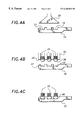
- FIGS. 4A-C is a schematic diagram showing a method of brush production according to the invention.
- FIG. 1 shows an injection-molded handle for a brush including pre-cored holes.
- a cross-section of several exemplary holes 15 is shown in FIGS. 2A-E.
- Each hole has a wall 17 and a bottom 19 , from which a protrusion 21 of excess material projects into the hole 15 .
- the protrusion 21 is formed during injection molding of the brush handle, including head 10 .
- the brush handle may be compression molded.
- the protrusion may be formed in a variety of shapes and sizes with respect to the hole.
- the protrusion may be the same shape as the hole. Alternatively, it may be square, circular, triangular, or elliptical, or it may have an irregular shape including any combination of curved and shaped sides.
- the handle may be molded with a plurality of protrusions in any given hole.
- the protrusion need not be solid; it can be annular or adopt some other outline of a shape.
- An upper surface 22 of the protrusion may be flat, curved, or stepped, or it may be formed with some other 3-dimensional profile. Neither a side surface 23 of protrusion 21 nor the wall 17 need be perpendicular to the bottom 19 of hole 15 . Because the hole 15 can take on a variety of shapes, the protrusion 21 may be adjusted accordingly to provide an optimal distribution of material, as shown in FIGS. 2A-E and 3 A-D.
- the handle configuration can be used for a variety of fusion processes.
- bristles are fed into a magazine at a station on a circular conveyor.
- the bristle bundles may be fed through holes in the magazine from an endless supply and cut to the desired length.
- the bristles may be fed into the magazine from a pre-cut supply.
- the holes in the magazine are configured to match the arrangement of holes in the handle, which may adopt a variety of shapes and sizes.
- the bristles are end-rounded and profiled.
- Appropriate-end-rounding and profiling methods are well-known in the art. In general, end-rounding is performed by sanding pads which rotate in an elliptical motion, abrading the end of the bristles to round the sharp comers.
- Profiling may be performed by any of several techniques. In one exemplary technique, pins approach the cut bundles from both the front and back sides of the magazine and push against the bundles, adjusting both the bundle heights and surface profile. Following profiling, the non-use ends of the bristles are trimmed to leave an even profile. During profiling and/or trimming, extra bristle strands may be added to the bundle.
- the ends of the bristles are fixed in the brush head.
- the non-use ends of the bristles are heated to form a small ball, called a fuse-ball or simply a fuse.
- the bristles are heated by a non-contact heater.
- the fuses may also be formed by a contact heater or hot air cannon, or chemically by softening a portion of the bristles with a solvent.
- the brush head 10 is also heated, preferably by a non-contact heater 30 , as shown in FIG. 4 A.
- a magazine 32 is shown holding bristle bundles 34 just before fused ends 36 are inserted into holes 15 .
- the diameter of the hole 15 is typically larger than that of the fuse 36 .
- the fuse 36 is inserted into the hole 15 , the excess material in protrusion 21 flows around the fuse 36 to fix the bristles 34 in the hole 15 .
- the fuse 36 is retained in the head 10 of the brush without expanding the walls 17 of the hole 15 , as shown in FIG. 4 C.
- the heated material in the head 10 may flow somewhat.
- the face 35 of the magazine 32 from which the fused ends 36 of the bristles 34 project may be contoured or stepped to mold the flowing material and provide a shape to the face of the head 10 , and a portion of the walls 17 may be swaged around the fuses 36 .
- the completed brushes are ejected from the machine, and the used magazine 32 returned to the beginning of the conveyor to begin the process anew.
Abstract
Description
Claims (6)
Priority Applications (4)
| Application Number | Priority Date | Filing Date | Title |
|---|---|---|---|
| US09/465,209 US6260928B1 (en) | 1999-12-15 | 1999-12-15 | Handle Configuration for brush production by fusion |
| PCT/US2000/034172 WO2001043587A1 (en) | 1999-12-15 | 2000-12-15 | Handle configuration for brush production by fusion |
| AU21077/01A AU2107701A (en) | 1999-12-15 | 2000-12-15 | Handle configuration for brush production by fusion |
| US09/836,779 US6752949B2 (en) | 1999-12-15 | 2001-04-17 | Handle configuration for brush production by fusion |
Applications Claiming Priority (1)
| Application Number | Priority Date | Filing Date | Title |
|---|---|---|---|
| US09/465,209 US6260928B1 (en) | 1999-12-15 | 1999-12-15 | Handle Configuration for brush production by fusion |
Related Child Applications (1)
| Application Number | Title | Priority Date | Filing Date |
|---|---|---|---|
| US09/836,779 Continuation-In-Part US6752949B2 (en) | 1999-12-15 | 2001-04-17 | Handle configuration for brush production by fusion |
Publications (1)
| Publication Number | Publication Date |
|---|---|
| US6260928B1 true US6260928B1 (en) | 2001-07-17 |
Family
ID=23846883
Family Applications (2)
| Application Number | Title | Priority Date | Filing Date |
|---|---|---|---|
| US09/465,209 Expired - Lifetime US6260928B1 (en) | 1999-12-15 | 1999-12-15 | Handle Configuration for brush production by fusion |
| US09/836,779 Expired - Lifetime US6752949B2 (en) | 1999-12-15 | 2001-04-17 | Handle configuration for brush production by fusion |
Family Applications After (1)
| Application Number | Title | Priority Date | Filing Date |
|---|---|---|---|
| US09/836,779 Expired - Lifetime US6752949B2 (en) | 1999-12-15 | 2001-04-17 | Handle configuration for brush production by fusion |
Country Status (3)
| Country | Link |
|---|---|
| US (2) | US6260928B1 (en) |
| AU (1) | AU2107701A (en) |
| WO (1) | WO2001043587A1 (en) |
Cited By (2)
| Publication number | Priority date | Publication date | Assignee | Title |
|---|---|---|---|---|
| US20020166188A1 (en) * | 2001-05-12 | 2002-11-14 | Georges Driesen | Toothbrush head |
| JP2013031537A (en) * | 2011-08-01 | 2013-02-14 | State Kogyo Kk | Brush and method for manufacturing the same |
Families Citing this family (6)
| Publication number | Priority date | Publication date | Assignee | Title |
|---|---|---|---|---|
| MXPA04007627A (en) * | 2002-12-03 | 2004-11-10 | Young Jun Kwon | Toothbrush having needle-shaped bristle tapered at one end and manufacturing method thereof. |
| DE202006007492U1 (en) * | 2005-06-24 | 2006-08-24 | Jenner, Günter | Connecting part for applicators |
| CN101371004B (en) * | 2005-12-20 | 2012-02-22 | 坎里格钻探技术有限公司 | Modular top drive |
| ES2830074T3 (en) | 2014-12-19 | 2021-06-02 | Mc Schiffer Gmbh | Brush and procedure for its production |
| MX2018012073A (en) | 2016-04-20 | 2019-05-22 | Trisa Holding Ag | Brush product and method for the production thereof. |
| US10563770B2 (en) * | 2016-05-05 | 2020-02-18 | National Oilwell Varco, L.P. | Washpipe assemblies for a power swivel |
Citations (10)
| Publication number | Priority date | Publication date | Assignee | Title |
|---|---|---|---|---|
| US2488873A (en) * | 1945-01-12 | 1949-11-22 | Prophylactic Brush Co | Toothbrush and method of making |
| US3641610A (en) * | 1970-02-11 | 1972-02-15 | Tucel Industries | Artificial tufted sponges |
| US4609228A (en) | 1984-01-10 | 1986-09-02 | Schlesinger Gmbh & Co. Maschinenbau Kg | Method and machine for manufacturing brushes |
| US4637660A (en) | 1984-02-01 | 1987-01-20 | Coronet-Werke Heinrich Schlerf Gmbh | Method for connecting bristles to a bristle carrier |
| US4892698A (en) * | 1985-03-29 | 1990-01-09 | Coronet-Werke Heinrich Schlerf Gmbh | Method for manufacturing products with bristles |
| US4988146A (en) | 1988-08-23 | 1991-01-29 | Coronet-Werke Heinrich Schlerf Gmbh | Process for the production of bristle articles |
| US5224763A (en) | 1991-12-30 | 1993-07-06 | The Procter & Gamble Company | Method of fastening bristle tufts to bristle carrier |
| US5474366A (en) * | 1993-02-02 | 1995-12-12 | Anton Zahoransky | Method of assembling a brush having bristles |
| US5622411A (en) | 1990-08-28 | 1997-04-22 | Coronet-Werke Heinrich Schlerf Gmbh | Process for joining bristle bundles to a plastic bristle carrier and apparatus for the same |
| US5823633A (en) * | 1994-05-05 | 1998-10-20 | Coronet-Werk Gmbh | Process for the production of brushware by injection moulding and brushware produced by it |
Family Cites Families (4)
| Publication number | Priority date | Publication date | Assignee | Title |
|---|---|---|---|---|
| JPS60215306A (en) * | 1984-04-11 | 1985-10-28 | ライオン株式会社 | Toothbrush |
| ATE110942T1 (en) * | 1989-06-24 | 1994-09-15 | Frisetta Gmbh | METHOD AND DEVICE FOR MANUFACTURING BRISTLE AREAS OR BRISTLE BUNDLES. |
| DE4027288C2 (en) * | 1990-08-29 | 2001-08-09 | Coronet Werke Gmbh | Device for producing bristle bundles and method for producing bristle goods by means of the device |
| DE19853030A1 (en) * | 1998-11-18 | 2000-05-25 | Coronet Werke Gmbh | Process for the production of bristle goods and device for carrying out the process |
-
1999
- 1999-12-15 US US09/465,209 patent/US6260928B1/en not_active Expired - Lifetime
-
2000
- 2000-12-15 WO PCT/US2000/034172 patent/WO2001043587A1/en active Application Filing
- 2000-12-15 AU AU21077/01A patent/AU2107701A/en not_active Abandoned
-
2001
- 2001-04-17 US US09/836,779 patent/US6752949B2/en not_active Expired - Lifetime
Patent Citations (10)
| Publication number | Priority date | Publication date | Assignee | Title |
|---|---|---|---|---|
| US2488873A (en) * | 1945-01-12 | 1949-11-22 | Prophylactic Brush Co | Toothbrush and method of making |
| US3641610A (en) * | 1970-02-11 | 1972-02-15 | Tucel Industries | Artificial tufted sponges |
| US4609228A (en) | 1984-01-10 | 1986-09-02 | Schlesinger Gmbh & Co. Maschinenbau Kg | Method and machine for manufacturing brushes |
| US4637660A (en) | 1984-02-01 | 1987-01-20 | Coronet-Werke Heinrich Schlerf Gmbh | Method for connecting bristles to a bristle carrier |
| US4892698A (en) * | 1985-03-29 | 1990-01-09 | Coronet-Werke Heinrich Schlerf Gmbh | Method for manufacturing products with bristles |
| US4988146A (en) | 1988-08-23 | 1991-01-29 | Coronet-Werke Heinrich Schlerf Gmbh | Process for the production of bristle articles |
| US5622411A (en) | 1990-08-28 | 1997-04-22 | Coronet-Werke Heinrich Schlerf Gmbh | Process for joining bristle bundles to a plastic bristle carrier and apparatus for the same |
| US5224763A (en) | 1991-12-30 | 1993-07-06 | The Procter & Gamble Company | Method of fastening bristle tufts to bristle carrier |
| US5474366A (en) * | 1993-02-02 | 1995-12-12 | Anton Zahoransky | Method of assembling a brush having bristles |
| US5823633A (en) * | 1994-05-05 | 1998-10-20 | Coronet-Werk Gmbh | Process for the production of brushware by injection moulding and brushware produced by it |
Cited By (3)
| Publication number | Priority date | Publication date | Assignee | Title |
|---|---|---|---|---|
| US20020166188A1 (en) * | 2001-05-12 | 2002-11-14 | Georges Driesen | Toothbrush head |
| US6957468B2 (en) * | 2001-05-12 | 2005-10-25 | Braun Gmbh | Toothbrush head with anchor-free bristle tufting |
| JP2013031537A (en) * | 2011-08-01 | 2013-02-14 | State Kogyo Kk | Brush and method for manufacturing the same |
Also Published As
| Publication number | Publication date |
|---|---|
| WO2001043587A1 (en) | 2001-06-21 |
| US20020069473A1 (en) | 2002-06-13 |
| US6752949B2 (en) | 2004-06-22 |
| AU2107701A (en) | 2001-06-25 |
Similar Documents
| Publication | Publication Date | Title |
|---|---|---|
| KR102607712B1 (en) | Brush manufacturing method and device | |
| CA2596685C (en) | Toothbrush | |
| RU2770726C2 (en) | Method for manufacturing brush head using molded bundle holder and support plate, as well as brush head | |
| MXPA04006236A (en) | Toothbrush and method for production of such a toothbrush. | |
| CN101849859A (en) | Head toothbrushes | |
| CN109414110B (en) | Method and apparatus for manufacturing brushes | |
| US6036277A (en) | Method for the manufacture of brushware | |
| US6260928B1 (en) | Handle Configuration for brush production by fusion | |
| WO2001056766A3 (en) | Apparatus and method for producing brushware by injection molding | |
| EA000153B1 (en) | Method and device for producing bristled articles produced according thereto | |
| TWI751315B (en) | Method and equipment for manufacturing brush and injection molding half mold part | |
| CN111387690A (en) | Brush head and manufacturing method thereof | |
| KR100263035B1 (en) | Toothbrush manufacturing method and apparatus | |
| CN110461190A (en) | For manufacturing half module of method and apparatus and injection moulding of brush | |
| KR20200030203A (en) | Toothbrush manufacturing method | |
| JPH09252845A (en) | Manufacture of brush | |
| JPH09220126A (en) | Brush producing method | |
| JPH0956479A (en) | Brush and its manufacture | |
| US6354911B1 (en) | Method and apparatus for end-rounding bristles | |
| JPH1052323A (en) | Manufacture of brush | |
| JPH0956477A (en) | Brush manufacturing method | |
| KR20200030204A (en) | Toothbrush manufacturing method utlizing toothbrush head kit | |
| JPH09182629A (en) | Manufacture of brush and its device |
Legal Events
| Date | Code | Title | Description |
|---|---|---|---|
| AS | Assignment |
Owner name: MOLL INDUSTRIES, INC., TENNESSEE Free format text: ASSIGNMENT OF ASSIGNORS INTEREST;ASSIGNORS:COLLINS, JAMES;BUCKNER, CARROLL;BIBLE, KENAN;AND OTHERS;REEL/FRAME:010948/0977;SIGNING DATES FROM 20000412 TO 20000606 |
|
| AS | Assignment |
Owner name: BANK OF AMERICA, N.A., AS AGENT FOR ITSELF AND OTH Free format text: SECURITY INTEREST;ASSIGNOR:MOLL INDUSTRIES, INC.;REEL/FRAME:011044/0293 Effective date: 20000809 |
|
| STCF | Information on status: patent grant |
Free format text: PATENTED CASE |
|
| AS | Assignment |
Owner name: BANK OF AMERICA, N.A., ILLINOIS Free format text: SECURITY AGREEMENT;ASSIGNOR:MOLL INDUSTRIES, INC.;REEL/FRAME:012607/0529 Effective date: 20011221 |
|
| AS | Assignment |
Owner name: FOOTHILL CAPITAL CORPORAITON, AS AGENT, GEORGIA Free format text: ASSIGNMENT OF SECURITY AGREEMENT;ASSIGNOR:BANK OF AMERICA, N.A., AS AGENT FOR ITSELF AND OTHER LENDERS;REEL/FRAME:013101/0243 Effective date: 20020708 |
|
| AS | Assignment |
Owner name: TEAM TECHNOLOGIES, INC. (A TENNESSEE CORPORATION), Free format text: ASSET PURCHASE AGREEMENT;ASSIGNOR:MOLL INDUSTRIES, INC., ( A DELAWARE CORPORATION);REEL/FRAME:014515/0783 Effective date: 20030211 |
|
| FEPP | Fee payment procedure |
Free format text: PAYOR NUMBER ASSIGNED (ORIGINAL EVENT CODE: ASPN); ENTITY STATUS OF PATENT OWNER: SMALL ENTITY Free format text: PAT HOLDER CLAIMS SMALL ENTITY STATUS, ENTITY STATUS SET TO SMALL (ORIGINAL EVENT CODE: LTOS); ENTITY STATUS OF PATENT OWNER: SMALL ENTITY |
|
| FPAY | Fee payment |
Year of fee payment: 4 |
|
| FPAY | Fee payment |
Year of fee payment: 8 |
|
| FPAY | Fee payment |
Year of fee payment: 12 |
|
| AS | Assignment |
Owner name: TEAM TECHNOLOGIES, INC., TENNESSEE Free format text: NOTICE OF RELEASE OF SECURITY INTERESTS;ASSIGNORS:BANK OF AMERICA, N.A.;FOOTHILL CAPITAL CORPORATION;REEL/FRAME:029469/0755 Effective date: 20030311 |
|
| AS | Assignment |
Owner name: TEAM TECHNOLOGIES ACQUISITION COMPANY, TENNESSEE Free format text: ASSIGNMENT OF ASSIGNORS INTEREST;ASSIGNOR:TEAM TECHNOLOGIES, INC.;REEL/FRAME:029482/0257 Effective date: 20121217 |
|
| AS | Assignment |
Owner name: GENERAL ELECTRIC CAPITAL CORPORATION, AS ADMINISTR Free format text: SECURITY AGREEMENT;ASSIGNOR:TEAM TECHNOLOGIES ACQUISITION COMPANY;REEL/FRAME:029490/0662 Effective date: 20121217 |
|
| AS | Assignment |
Owner name: TEAM TECHNOLOGIES ACQUISITION COMPANY, TENNESSEE Free format text: ASSIGNMENT OF ASSIGNORS INTEREST;ASSIGNOR:TEAM TECHNOLOGIES, INC.;REEL/FRAME:029604/0405 Effective date: 20121217 Owner name: TEAM TECHNOLOGIES ACQUISITION COMPANY, TENNESSEE Free format text: REQUEST FOR NULLIFICATION OF ASSIGNMENT RECORDED ON 12/17/12 ON REEL/FRAME 29482/0257;ASSIGNOR:TEAM TECHNOLOGIES, INC.;REEL/FRAME:029601/0825 Effective date: 20121217 |
|
| AS | Assignment |
Owner name: TEAM TECHNOLOGIES, INC., TENNESSEE Free format text: CHANGE OF NAME;ASSIGNOR:TEAM TECHNOLOGIES ACQUISITION COMPANY;REEL/FRAME:029610/0364 Effective date: 20121221 |
|
| AS | Assignment |
Owner name: ANTARES CAPITAL LP, ILLINOIS Free format text: ASSIGNMENT OF INTELLECTUAL PROPERTY SECURITY AGREEMENT;ASSIGNOR:GENERAL ELECTRIC CAPITAL CORPORATION;REEL/FRAME:036552/0170 Effective date: 20150821 |
|
| AS | Assignment |
Owner name: THE NORTHWESTERN MUTUAL LIFE INSURANCE COMPANY, AS COLLATERAL AGENT, WISCONSIN Free format text: GRANT OF SECOND LIEN SECURITY INTEREST IN UNITED STATES PATENTS;ASSIGNORS:TEAM TECHNOLOGIES, INC.;PROTEXER, INC.;ICP MEDICAL, LLC;AND OTHERS;REEL/FRAME:047581/0537 Effective date: 20181115 Owner name: THE NORTHWESTERN MUTUAL LIFE INSURANCE COMPANY, AS Free format text: GRANT OF SECOND LIEN SECURITY INTEREST IN UNITED STATES PATENTS;ASSIGNORS:TEAM TECHNOLOGIES, INC.;PROTEXER, INC.;ICP MEDICAL, LLC;AND OTHERS;REEL/FRAME:047581/0537 Effective date: 20181115 |
|
| AS | Assignment |
Owner name: ACF FINCO I LP, NEW JERSEY Free format text: SECURITY INTEREST;ASSIGNORS:TEAM TECHNOLOGIES, INC.;PROTEXER, INC.;ICP MEDICAL, LLC;AND OTHERS;REEL/FRAME:047582/0956 Effective date: 20181115 Owner name: ARES CAPITAL CORPORATION, NEW YORK Free format text: FIRST LIEN SECURITY INTEREST;ASSIGNORS:TEAM TECHNOLOGIES, INC.;PROTEXER, INC.;ICP MEDICAL, LLC;AND OTHERS;REEL/FRAME:047583/0067 Effective date: 20181115 |
|
| AS | Assignment |
Owner name: TEAM TECHNOLOGIES ACQUISITION COMPANY, TENNESSEE Free format text: RELEASE BY SECURED PARTY;ASSIGNOR:ANTARES CAPITAL LP, AS AGENT;REEL/FRAME:047582/0913 Effective date: 20181115 |
|
| AS | Assignment |
Owner name: DOSELOGIX, LLC, TENNESSEE Free format text: RELEASE OF SECOND LIEN SECURITY INTEREST IN PATENTS RECORDED AT REEL/FRAME NO.: 047581/0537;ASSIGNOR:THE NORTHWESTERN MUTUAL LIFE INSURANCE COMPANY, AS COLLATERAL AGENT;REEL/FRAME:058642/0583 Effective date: 20211231 Owner name: ICP MEDICAL, LLC, TENNESSEE Free format text: RELEASE OF SECOND LIEN SECURITY INTEREST IN PATENTS RECORDED AT REEL/FRAME NO.: 047581/0537;ASSIGNOR:THE NORTHWESTERN MUTUAL LIFE INSURANCE COMPANY, AS COLLATERAL AGENT;REEL/FRAME:058642/0583 Effective date: 20211231 Owner name: PROTEXER, INC., TENNESSEE Free format text: RELEASE OF SECOND LIEN SECURITY INTEREST IN PATENTS RECORDED AT REEL/FRAME NO.: 047581/0537;ASSIGNOR:THE NORTHWESTERN MUTUAL LIFE INSURANCE COMPANY, AS COLLATERAL AGENT;REEL/FRAME:058642/0583 Effective date: 20211231 Owner name: TEAM TECHNOLOGIES, INC., TENNESSEE Free format text: RELEASE OF SECOND LIEN SECURITY INTEREST IN PATENTS RECORDED AT REEL/FRAME NO.: 047581/0537;ASSIGNOR:THE NORTHWESTERN MUTUAL LIFE INSURANCE COMPANY, AS COLLATERAL AGENT;REEL/FRAME:058642/0583 Effective date: 20211231 Owner name: DOSELOGIX, LLC, TENNESSEE Free format text: RELEASE OF SECURITY INTEREST IN PATENTS RECORDED AT REEL/FRAME NO.: 047582/0956;ASSIGNOR:ACF FINCO I LP;REEL/FRAME:058643/0955 Effective date: 20211231 Owner name: ICP MEDICAL, LLC, TENNESSEE Free format text: RELEASE OF SECURITY INTEREST IN PATENTS RECORDED AT REEL/FRAME NO.: 047582/0956;ASSIGNOR:ACF FINCO I LP;REEL/FRAME:058643/0955 Effective date: 20211231 Owner name: PROTEXER, INC., TENNESSEE Free format text: RELEASE OF SECURITY INTEREST IN PATENTS RECORDED AT REEL/FRAME NO.: 047582/0956;ASSIGNOR:ACF FINCO I LP;REEL/FRAME:058643/0955 Effective date: 20211231 Owner name: TEAM TECHNOLOGIES, INC., TENNESSEE Free format text: RELEASE OF SECURITY INTEREST IN PATENTS RECORDED AT REEL/FRAME NO.: 047582/0956;ASSIGNOR:ACF FINCO I LP;REEL/FRAME:058643/0955 Effective date: 20211231 Owner name: DOSELOGIX, LLC, TENNESSEE Free format text: RELEASE OF FIRST LIEN SECURITY INTEREST IN PATENTS RECORDED AT REEL/FRAME NO.: 047583/0067;ASSIGNOR:ARES CAPITAL CORPORATION;REEL/FRAME:058577/0528 Effective date: 20211231 Owner name: ICP MEDICAL, LLC, TENNESSEE Free format text: RELEASE OF FIRST LIEN SECURITY INTEREST IN PATENTS RECORDED AT REEL/FRAME NO.: 047583/0067;ASSIGNOR:ARES CAPITAL CORPORATION;REEL/FRAME:058577/0528 Effective date: 20211231 Owner name: PROTEXER, INC., TENNESSEE Free format text: RELEASE OF FIRST LIEN SECURITY INTEREST IN PATENTS RECORDED AT REEL/FRAME NO.: 047583/0067;ASSIGNOR:ARES CAPITAL CORPORATION;REEL/FRAME:058577/0528 Effective date: 20211231 Owner name: TEAM TECHNOLOGIES, INC., TENNESSEE Free format text: RELEASE OF FIRST LIEN SECURITY INTEREST IN PATENTS RECORDED AT REEL/FRAME NO.: 047583/0067;ASSIGNOR:ARES CAPITAL CORPORATION;REEL/FRAME:058577/0528 Effective date: 20211231 |