EP2533590B1 - Mobile station device and wireless communication method - Google Patents
Mobile station device and wireless communication method Download PDFInfo
- Publication number
- EP2533590B1 EP2533590B1 EP11739610.1A EP11739610A EP2533590B1 EP 2533590 B1 EP2533590 B1 EP 2533590B1 EP 11739610 A EP11739610 A EP 11739610A EP 2533590 B1 EP2533590 B1 EP 2533590B1
- Authority
- EP
- European Patent Office
- Prior art keywords
- station apparatus
- reference signal
- mobile station
- transmission
- srs
- Prior art date
- Legal status (The legal status is an assumption and is not a legal conclusion. Google has not performed a legal analysis and makes no representation as to the accuracy of the status listed.)
- Active
Links
- 238000004891 communication Methods 0.000 title claims description 51
- 238000000034 method Methods 0.000 title claims description 20
- 230000005540 biological transmission Effects 0.000 claims description 202
- 238000007726 management method Methods 0.000 description 14
- 238000013468 resource allocation Methods 0.000 description 11
- 230000011664 signaling Effects 0.000 description 11
- 230000000694 effects Effects 0.000 description 7
- 238000012545 processing Methods 0.000 description 7
- 239000000969 carrier Substances 0.000 description 5
- 238000010586 diagram Methods 0.000 description 4
- 238000005516 engineering process Methods 0.000 description 4
- 230000006870 function Effects 0.000 description 4
- 238000012935 Averaging Methods 0.000 description 3
- 101000741965 Homo sapiens Inactive tyrosine-protein kinase PRAG1 Proteins 0.000 description 3
- 102100038659 Inactive tyrosine-protein kinase PRAG1 Human genes 0.000 description 3
- 238000013507 mapping Methods 0.000 description 3
- 230000000737 periodic effect Effects 0.000 description 3
- 230000004044 response Effects 0.000 description 3
- 230000002776 aggregation Effects 0.000 description 2
- 238000004220 aggregation Methods 0.000 description 2
- 230000015572 biosynthetic process Effects 0.000 description 2
- 238000001914 filtration Methods 0.000 description 2
- 238000003780 insertion Methods 0.000 description 2
- 230000037431 insertion Effects 0.000 description 2
- 230000010354 integration Effects 0.000 description 2
- 230000007774 longterm Effects 0.000 description 2
- 230000015654 memory Effects 0.000 description 2
- 238000003786 synthesis reaction Methods 0.000 description 2
- 235000008694 Humulus lupulus Nutrition 0.000 description 1
- 230000003044 adaptive effect Effects 0.000 description 1
- 230000001413 cellular effect Effects 0.000 description 1
- 238000006243 chemical reaction Methods 0.000 description 1
- 239000002131 composite material Substances 0.000 description 1
- 238000012790 confirmation Methods 0.000 description 1
- 238000007796 conventional method Methods 0.000 description 1
- 125000004122 cyclic group Chemical group 0.000 description 1
- VJYFKVYYMZPMAB-UHFFFAOYSA-N ethoprophos Chemical compound CCCSP(=O)(OCC)SCCC VJYFKVYYMZPMAB-UHFFFAOYSA-N 0.000 description 1
- 239000000284 extract Substances 0.000 description 1
- 239000011159 matrix material Substances 0.000 description 1
- 238000010295 mobile communication Methods 0.000 description 1
- 230000002093 peripheral effect Effects 0.000 description 1
- 239000004065 semiconductor Substances 0.000 description 1
Images


Classifications
-
- H—ELECTRICITY
- H04—ELECTRIC COMMUNICATION TECHNIQUE
- H04W—WIRELESS COMMUNICATION NETWORKS
- H04W72/00—Local resource management
- H04W72/04—Wireless resource allocation
- H04W72/044—Wireless resource allocation based on the type of the allocated resource
- H04W72/0453—Resources in frequency domain, e.g. a carrier in FDMA
-
- H—ELECTRICITY
- H04—ELECTRIC COMMUNICATION TECHNIQUE
- H04B—TRANSMISSION
- H04B1/00—Details of transmission systems, not covered by a single one of groups H04B3/00 - H04B13/00; Details of transmission systems not characterised by the medium used for transmission
- H04B1/69—Spread spectrum techniques
- H04B1/713—Spread spectrum techniques using frequency hopping
-
- H—ELECTRICITY
- H04—ELECTRIC COMMUNICATION TECHNIQUE
- H04B—TRANSMISSION
- H04B7/00—Radio transmission systems, i.e. using radiation field
- H04B7/02—Diversity systems; Multi-antenna system, i.e. transmission or reception using multiple antennas
- H04B7/04—Diversity systems; Multi-antenna system, i.e. transmission or reception using multiple antennas using two or more spaced independent antennas
-
- H—ELECTRICITY
- H04—ELECTRIC COMMUNICATION TECHNIQUE
- H04J—MULTIPLEX COMMUNICATION
- H04J11/00—Orthogonal multiplex systems, e.g. using WALSH codes
-
- H—ELECTRICITY
- H04—ELECTRIC COMMUNICATION TECHNIQUE
- H04L—TRANSMISSION OF DIGITAL INFORMATION, e.g. TELEGRAPHIC COMMUNICATION
- H04L5/00—Arrangements affording multiple use of the transmission path
- H04L5/003—Arrangements for allocating sub-channels of the transmission path
- H04L5/0048—Allocation of pilot signals, i.e. of signals known to the receiver
-
- H—ELECTRICITY
- H04—ELECTRIC COMMUNICATION TECHNIQUE
- H04L—TRANSMISSION OF DIGITAL INFORMATION, e.g. TELEGRAPHIC COMMUNICATION
- H04L5/00—Arrangements affording multiple use of the transmission path
- H04L5/003—Arrangements for allocating sub-channels of the transmission path
- H04L5/0053—Allocation of signaling, i.e. of overhead other than pilot signals
-
- H—ELECTRICITY
- H04—ELECTRIC COMMUNICATION TECHNIQUE
- H04L—TRANSMISSION OF DIGITAL INFORMATION, e.g. TELEGRAPHIC COMMUNICATION
- H04L5/00—Arrangements affording multiple use of the transmission path
- H04L5/0091—Signaling for the administration of the divided path
-
- H—ELECTRICITY
- H04—ELECTRIC COMMUNICATION TECHNIQUE
- H04W—WIRELESS COMMUNICATION NETWORKS
- H04W74/00—Wireless channel access
- H04W74/002—Transmission of channel access control information
- H04W74/004—Transmission of channel access control information in the uplink, i.e. towards network
-
- H—ELECTRICITY
- H04—ELECTRIC COMMUNICATION TECHNIQUE
- H04W—WIRELESS COMMUNICATION NETWORKS
- H04W74/00—Wireless channel access
- H04W74/002—Transmission of channel access control information
- H04W74/006—Transmission of channel access control information in the downlink, i.e. towards the terminal
-
- H—ELECTRICITY
- H04—ELECTRIC COMMUNICATION TECHNIQUE
- H04W—WIRELESS COMMUNICATION NETWORKS
- H04W76/00—Connection management
- H04W76/20—Manipulation of established connections
- H04W76/27—Transitions between radio resource control [RRC] states
-
- H—ELECTRICITY
- H04—ELECTRIC COMMUNICATION TECHNIQUE
- H04L—TRANSMISSION OF DIGITAL INFORMATION, e.g. TELEGRAPHIC COMMUNICATION
- H04L5/00—Arrangements affording multiple use of the transmission path
- H04L5/0001—Arrangements for dividing the transmission path
- H04L5/0003—Two-dimensional division
- H04L5/0005—Time-frequency
- H04L5/0007—Time-frequency the frequencies being orthogonal, e.g. OFDM(A), DMT
- H04L5/0012—Hopping in multicarrier systems
-
- H—ELECTRICITY
- H04—ELECTRIC COMMUNICATION TECHNIQUE
- H04L—TRANSMISSION OF DIGITAL INFORMATION, e.g. TELEGRAPHIC COMMUNICATION
- H04L5/00—Arrangements affording multiple use of the transmission path
- H04L5/0001—Arrangements for dividing the transmission path
- H04L5/0014—Three-dimensional division
- H04L5/0023—Time-frequency-space
-
- H—ELECTRICITY
- H04—ELECTRIC COMMUNICATION TECHNIQUE
- H04W—WIRELESS COMMUNICATION NETWORKS
- H04W72/00—Local resource management
- H04W72/20—Control channels or signalling for resource management
-
- H—ELECTRICITY
- H04—ELECTRIC COMMUNICATION TECHNIQUE
- H04W—WIRELESS COMMUNICATION NETWORKS
- H04W88/00—Devices specially adapted for wireless communication networks, e.g. terminals, base stations or access point devices
- H04W88/02—Terminal devices
-
- H—ELECTRICITY
- H04—ELECTRIC COMMUNICATION TECHNIQUE
- H04W—WIRELESS COMMUNICATION NETWORKS
- H04W88/00—Devices specially adapted for wireless communication networks, e.g. terminals, base stations or access point devices
- H04W88/08—Access point devices
Definitions
- the present invention relates to a radio communication system including a mobile station apparatus and a base station apparatus, and in particular, to a transmission control method of a reference signal for channel estimation for the mobile station apparatus.
- LTE-A Long Term Evolution-Advanced
- A-EUTRA Advanced Evolved Universal Terrestrial Radio Access
- A-SRS Aperiodic Sounding Reference Signal
- P-SRS Periodic Sounding Reference Signal
- Non-patent document 1 " Channel sounding enhancements for LTE-Advanced", R1-094653, 3GPP TSG-RAN1 Meeting#59, Jeju, Korea, Nov 9-13, 2009
- EP 2 023 504 A2 discloses a method and a system for selecting antennas in a wireless network, wherein sounding reference signals are sent according to specified times, frequencies, and antennas. The sounding reference signal is transmitted in a manner to cover an entire bandwidth by hopping a number of hops previously indicated.
- WO 2008/ 156293 A2 relates to a method of transmitting a sounding reference signal by using frequency hopping with a predetermined time period, in a predetermined pattern and for a predetermined time, as indicated in a Physical Downlink Control Channel.
- the base station apparatus cannot obtain adequate channel estimate accuracy for an uplink. Further, the mobile station apparatus transmits the reference signal that cannot provide adequate channel estimate accuracy, resulting in that a resource of an uplink signal is wasted, and efficient frequency selective scheduling cannot be performed also in the base station apparatus.
- the present invention has been made in view of the above-mentioned problems and has an object to provide a mobile station apparatus and a communication method of a mobile station apparatus that can efficiently transmit the reference signal for channel estimation when the transmission request is notified from the base station apparatus, thereby improving the channel estimate accuracy of the uplink.
- the above problems are solved by the subject-matter of the independent claims.
- the invention is defined by the appended claims. References to embodiments which do not fall under the scope of the claims are to be understood as examples useful for understanding the invention.
- the mobile station apparatus can transmit the A-SRS while performing antenna selection (switching) the predetermined number of times with one transmission request from the base station apparatus.
- the mobile station apparatus it is possible to provide the mobile station apparatus, the base station apparatus, the radio communication system and the radio communication method that can efficiently transmit the reference signal for channel estimation when the transmission request is notified from the base station apparatus, thereby improving the channel estimate accuracy of the uplink.
- Physical channels used in the present invention include a physical broadcast channel, physical downlink shared channel, a physical downlink control channel, a downlink reference signal, a physical uplink shared channel, a physical uplink control channel, a physical random access channel and an uplink reference signal. Even when a different type of physical channel is added to the above-mentioned physical channel, each of below-mentioned embodiments of the present invention can be applied.
- the physical broadcast channel is transmitted to provide notification of a control parameter (broadcast information) commonly used by the mobile station apparatus in a cell.
- a cell global ID indicating a cell-specific ID (Identity) is notified.
- a broadcast channel (BCH) is mapped at intervals of 40 milliseconds. The timing of 40 milliseconds is blind-detected in the mobile station apparatus. That is, due to the timing presentation of the physical broadcast channel, an explicit signaling is not transmitted to the mobile station apparatus.
- a subframe including the physical broadcast channel (PBCH) is self-decodable.
- the physical downlink control channel is a downlink channel transmitted from the base station apparatus to the mobile station apparatus, which is a channel used to notify the mobile station apparatus of resource allocation of the physical downlink shared channel (PDSCH), hybrid automatic repeat request (HARQ) information for downlink data (DL-SCH: Downlink-Shared Channel) and uplink transmission grant (uplink grant) as resource allocation of the physical uplink shared channel (PUSCH).
- PDSCH physical downlink shared channel
- HARQ hybrid automatic repeat request
- uplink grant uplink transmission grant
- the physical downlink shared channel is a channel used to transmit downlink data (DL-SCH: Downlink-Shared Channel) or paging information.
- the downlink reference signal (DL-RS: Downlink Reference Signal or Cell-specific Reference Signal) is transmitted using a downlink from the base station apparatus to the mobile station apparatus.
- the mobile station apparatus measures the downlink reference signal to determine the reception quality of the downlink.
- the reception quality is notified to the base station apparatus by use of the physical uplink control channel (PUCCH) or the physical uplink shared channel (PUSCH) as CQI (Channel Quality Indicator), which is quality information indicator.
- PUCCH physical uplink control channel
- PUSCH Physical uplink shared channel
- CQI Channel Quality Indicator
- reception quality examples include SIR (Signal-to-Interference Ratio), SINR (Signal-to-Interference plus Noise Ratio), SNR (Signal-to-Noise Ratio), CIR (Carrier-to-Interference Ratio), BLER (Block Error Rate) and path loss.
- SIR Signal-to-Interference Ratio
- SINR Signal-to-Interference plus Noise Ratio
- SNR Signal-to-Noise Ratio
- CIR Carrier-to-Interference Ratio
- BLER Block Error Rate
- the physical uplink shared channel is a channel used to transmit mainly uplink data (UL-SCH: Uplink Shared Channel).
- UL-SCH Uplink Shared Channel
- channel status information downlink channel quality indicator (CQI)
- PMI precoding matrix indicator
- RI rank indicator
- ACK acknowledgement response
- NACK Negative Acknowledgement
- HARQ hybrid automatic repeat request
- the uplink data indicates, for example, transmission of user data
- the UL-SCH is a transport channel.
- the HARQ and dynamic adaptive radio link control is supported, and beam forming is available.
- dynamic resource allocation and quasi-static resource allocation are supported.
- the physical uplink control channel is a channel used to transmit control data.
- control data include channel status information (CQI, PMI, RI) transmitted (fed back) from the mobile station apparatus to the base station apparatus, scheduling request (SR) to request resource allocation for transmission of the uplink data by the mobile station apparatus (to request transmission in the UL-SCH) and ACK/NACK to the HARQ for the downlink transmission.
- CQI, PMI, RI channel status information
- SR scheduling request
- ACK/NACK ACK/NACK to the HARQ for the downlink transmission.
- the uplink reference signal (UL-RS) is transmitted from the mobile station apparatus to the base station apparatus.
- the UL-RS is classified into a sounding reference signal (SRS) and a demodulation reference signal (DM-RS).
- the sounding reference signal as a reference signal for channel estimation is measured by the base station apparatus to determine the reception quality of an uplink radio transmission signal of the mobile station apparatus, and is used to adjust uplink scheduling and uplink timing synchronization on the basis of the reception quality.
- the demodulation reference signal is transmitted together with the physical uplink shared channel, and is used as the reference signal for calculating amplitude, phase and frequency change of a signal of the physical uplink shared channel and demodulating the signal transmitted by use of the physical uplink shared channel.
- a transmission frequency band of the DM-RS matches a transmission frequency band of the PUSCH, while a transmission frequency band of the SRS is set independently of the transmission frequency band of the DM-RS. That is, the transmission frequency band of the SRS does not necessarily match the transmission frequency band of the PUSCH and is previously set by the base station apparatus.
- Frequency hopping is applied to the SRS in a time axis direction. By using the frequency hopping, the SRS can obtain a frequency diversity effect and an interference averaging effect.
- a first reference signal (A-SRS: Aperiodic SRS) for channel estimation is a reference signal for channel estimation transmitted upon request from the base station apparatus, and a subframe transmitting the first reference signal may be set by use of the physical downlink control channel by the base station apparatus, or may be set by use of a radio resource control signal (RRC signaling).
- RRC signaling radio resource control signal
- a second reference signal (P-SRS: Periodic SRS) for channel estimation is a reference signal for channel estimation transmitted according to a transmission periodicity previously set by the base station apparatus, a subframe transmitting the second reference signal may be set by use of the radio resource control signal by the base station apparatus, or may be set by use of the broadcast channel.
- Configuration information on SRS parameters such as the transmission periodicity and the transmission frequency band of each of the first reference signal and the second reference signal may be previously set by the base station apparatus and then, the radio resource control signal including the configuration information may be transmitted to the mobile station apparatus.
- the subframe transmitting the reference signal for channel estimation may be set for each cell, set for each mobile station apparatus or set for each component carrier, or the subframe transmitting the first reference signal and the subframe transmitting the second reference signal may be the same as each other or different from each other.
- the base station apparatus may set the subframe transmitting the first reference signal for each mobile station apparatus, and set the subframe transmitting the second reference signal for each cell.
- the physical random access channel is a physical channel used to transmit a random access preamble, and has guard time.
- the PRACH has a main object to allow the mobile station apparatus to synchronize with the base station apparatus, and is also used for initial access, handover, reconnection request and scheduling request.
- the scheduling request is information that the mobile station apparatus requests resource allocation of the physical uplink shared channel to the base station apparatus.
- the mobile station apparatus When the mobile station apparatus accumulates information data to be transmitted in its buffer and requests resource allocation of the physical uplink shared channel, the mobile station apparatus transmits the scheduling request. Using the physical uplink control channel previously allocated by the base station apparatus, the mobile station apparatus also transmits the scheduling request to the base station apparatus.
- the base station apparatus allocates a periodic resource for arrangement of the scheduling request by the mobile station apparatus.
- Fig. 6 is a view schematically showing a configuration of SRS resource allocation and frequency hopping (FH).
- a horizontal axis represents time and a vertical axis represents frequency.
- a left side shows one example of SRS resource allocation.
- 14 symbols are aligned in the time axis direction. Seven symbols correspond to 1 slot, and a length of 1 slot is 0.5 milliseconds (ms).
- the 14 symbols correspond to 2 slots
- the SRS is allocated to the 14 th symbol.
- the resource (bandwidth in the frequency direction) of the SRS allocated to the 14 th symbol is set according to an uplink system bandwidth and transmit power of the mobile station apparatus.
- the PRACH can change bandwidth and time symbol length according to the type and format of a message to be transmitted and allocate them.
- the frequency hopping changing frequency position at each transmission is applied in the time axis direction.
- a right side in this figure shows one example of SRS frequency hopping.
- the SRS is transmitted every transmission periodicity T, and as shown in the figure, hopping is performed in the frequency direction every periodicity T (that is, in each transmission).
- a base station apparatus 1 transmits the radio resource control signal including information indicating the number of times of transmission of a reference signal for channel estimation to a mobile station apparatus 3, and transmits a physical downlink control channel including information indicating transmission of the reference signal to the mobile station apparatus 3.
- the mobile station apparatus 3 sets the number of times of transmission of the reference signal according to the information indicating the number of times of transmission, which is included in the radio resource control signal, and when the information indicating transmission of the reference signal is included in the physical downlink control channel, the mobile station apparatus 3 transmits the reference signal to the base station apparatus 1.
- the mobile station apparatus 3 can transmit the A-SRS the predetermined number of times.
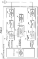
- Fig. 1 is a block diagram schematically showing a functional structure of the base station apparatus 1 according to the present invention.
- the base station apparatus 1 includes a transmitting part 101, a receiving part 103, a scheduling part 105, a higher layer 107 and an antenna 109.
- the transmitting part 101 includes a data control part 1011, a modulating part 1013 and a radio transmitting part 1015.
- the receiving part 103 includes a radio receiving part 1031, a demodulating part 1033 and a data extracting part 1035.
- the data control part 1011 receives inputs of user data and control data, and according to an instruction from the scheduling part 105, arranges the control data in the PDCCH and arranges transmit data to each mobile station apparatus 3 and the control data in the PDSCH.
- the modulating part 1013 executes signal processing such as data modulation, serial/parallel conversion of an input signal, IFFT, CP insertion and filtering, and generates a transmission signal.
- the radio transmitting part 1015 upconverts modulated data to a radio frequency and then, transmits it to the mobile station apparatus 3 via the antenna 109.
- the radio receiving part 1031 receives an uplink signal from the mobile station apparatus 3, down converts it to a baseband signal and outputs received data to the demodulating part 1033.
- the data extracting part 1035 confirms whether or not the received data is correct, and notifies a confirmation result to the scheduling part 105.
- the data extracting part 1035 divides the received data into the user data and the control data.
- the data extracting part 1035 outputs control data of the second layer in the control data, such as downlink channel quality instruction information and acknowledgment/negative acknowledgment (ACK/NACK) of downlink data, to the scheduling part 105, and outputs the control data of the third layer and the user data to the higher layer 107.
- the data extracting part 1035 stores the received data for synthesis with retransmission data, and when receiving the retransmission data, executes synthesis processing.
- the scheduling part 105 performs scheduling for arranging the user data and the control data in the PDSCH and the PDCCH.
- the higher layer 107 executes processing of a medium access control (MAC) layer, a radio link control (RLC) layer, a packet data convergence protocol (PDCP) layer and a radio resource control (RRC) layer.
- MAC medium access control
- RLC radio link control
- PDCP packet data convergence protocol
- RRC radio resource control
- the higher layer 107 also uses a radio resource control part 1071 (also referred to as a control part) .
- the radio resource control part 1071 performs management of various configuration information, management of system information, paging control, management of a communication status of each mobile station apparatus 3, mobility management such as handover, management of a buffer status of each mobile station apparatus 3, management of connection configuration of unicast and multicast bearers and management of a mobile station identifier (UEID).
- the higher layer 107 exchanges information with another base station apparatus 1 and an upper node.
- Fig. 2 is a block diagram schematically showing a functional structure of the mobile station apparatus 3 according to the present invention.
- the mobile station apparatus 3 includes a transmitting part 201, a receiving part 203, a scheduling part 205, a higher layer 207 and an antenna 209.
- the transmitting part 201 includes a data control part 2011, a modulating part 2013 and a radio transmitting part 2015.
- the receiving part 203 includes a radio receiving part 2031, a demodulating part 2033 and a data extracting part 2035.
- the user data and the control data are input from the higher layer 207 to the data control part 2011.
- the data control part 2011 arranges input data in the PUSCH and the PUCCH.
- the modulating part 2013 modulates the data in the PUSCH and the PUCCH and outputs modulated data to the radio transmitting part 2015.
- the radio transmitting part 2015 applies signal processing, such as discrete Fourier transform (DFT), subcarrier mapping, inverse fast Fourier transform (IFFT), CP (Cyclic Prefix) insertion and filtering, to the modulated data and an uplink reference signal to generate a transmission signal, upconverts it to radio frequency and then, transmits it to the base station apparatus 1 via the antenna 209.
- DFT discrete Fourier transform
- IFFT inverse fast Fourier transform
- CP Cyclic Prefix
- the radio receiving part 2031 receives a downlink signal from the base station apparatus 1, downconverts the signal to a baseband signal and outputs the received signal to the demodulating part 2033.
- the demodulating part 2033 demodulates received data.
- the data extracting part 2035 divides the received data into the user data and the control data.
- the data extracting part 2035 outputs the control data about scheduling information, random access response message and intermittent reception control, and other control data of the second layer to the control data scheduling part 205, and outputs the user data to the higher layer 207.
- the scheduling part 205 analyzes the control data input from the data extracting part 2035 and generates uplink scheduling information, and based on the scheduling information, instructs the data control part 2011 to allocate the user data and the control data to the PUSCH and the PUCCH.
- the scheduling part 205 further includes a reference signal control part 2051.
- the reference signal control part 2051 extracts SRS configuration information on the basis of the scheduling information transmitted from the base station apparatus 1. Various parameters of the first reference signal (A-SRS) and the second reference signal (P-SRS) are set based on the SRS configuration information. Transmission control in the case where the first reference signal and the second reference signal for channel estimation, and the physical uplink control channel occur in the same timing is performed to generate SRS transmission control information.
- the reference signal control part 2051 outputs the SRS configuration information and the SRS transmission control information to a reference signal generating part 206.
- the reference signal generating part 206 Based on the SRS configuration information and the SRS transmission control information, which are input from the reference signal control part 2051, the reference signal generating part 206 generates the first reference signal and/or the second reference signal and outputs the generated signal to the radio transmitting part 2015.
- the higher layer 207 executes processing of the medium access control (MAC) layer, the radio link control (RLC) layer, the packet data convergence protocol (PDCP) layer and the radio resource control (RRC) layer.
- An interface (not shown) between the higher layer 207, and the scheduling part 205, the antenna 209, the transmitting part 201, the receiving part 203 exists such that the higher layer 207 controls the processing parts of the lower layer together.
- the higher layer 207 has a radio resource control part 2071 (hereinafter referred to as a control part) .
- the radio resource control part 2071 performs management of various configuration information, management of system information, paging control, management of a communication status of a local station, mobility management such as handover, management of a buffer status, management of connection configuration of unicast and multicast bearers and management of a mobile station identifier (UEID).
- UEID mobile station identifier
- Fig. 3 is a view showing one example of signaling for A-SRS transmission in accordance with First embodiment of the present invention.
- the base station apparatus 1 transmits the radio resource control signal including the A-SRS configuration information to the mobile station apparatus 3 (Step S101).
- the base station apparatus 1 transmits the radio resource control signal including information indicating the number of times of A-SRS transmission (for example, the number of times of transmission is five) to the mobile station apparatus 3 (Step S102).
- the mobile station apparatus 3 sets various parameters of the A-SRS (including the number of times of transmission).
- the mobile station apparatus 3 transmits the A-SRS to the base station apparatus 1 until the number of times of transmission reaches the predetermined number of times (Step S104).
- the PDCCH includes a TPC (Transmit Power Control) command for A-SRS transmission. That is, according to the TPC command included in the PDCCH, the mobile station apparatus 3 transmits the A-SRS to the base station apparatus 1.
- the information indicating the number of times of A-SRS transmission may be included in the A-SRS configuration information.
- the parameters set by the SRS configuration information are the transmission frequency band and the transmission periodicity for A-SRS transmission and the transmission frequency band and the transmission periodicity for P-SRS transmission.
- the mobile station apparatus 3 may simultaneously transmit the A-SRS via the plurality of antennas.
- the mobile station apparatus 3 may ignore the information included in the new received PDCCH and transmit the A-SRS until the number of times of transmission of the reference signal reaches the predetermined number of times, or may stop transmission of A-SRS being transmitted, resets the number of times the mobile station apparatus 3 transmits the A-SRS, and transmit the new A-SRS requested from the base station apparatus 1 to the base station apparatus 1 until the number of times of transmission reaches the predetermined number of times.
- the mobile station apparatus 3 drops (does not transmit) the P-SRS and transmits the A-SRS to the base station apparatus 1.
- that the A-SRS and the P-SRS are allocated in the same timing means that, describing with reference to the left side in Fig. 6 , one mobile station apparatus 3 simultaneously arranges and transmits the A-SRS and the P-SRS to the 14 th symbol (shadow area) to which the A-SRS and the P-SRS are transmitted according to an instruction of the base station apparatus 1, and the transmission timing matches in units of symbol.
- the mobile station apparatus 3 can determine whether or not the A-SRS and the P-SRS are allocated in the 14 th symbol in the same timing.
- the base station apparatus 1 may set the subframe transmitting the A-SRS for each cell or for each mobile station apparatus 3.
- the subframe transmitting the A-SRS may include the subframe set for each cell and the subframe set for each mobile station apparatus 3.
- the base station apparatus 1 may set the subframe transmitting the A-SRS for each component carrier.
- the base station apparatus 1 may set the subframe transmitting the A-SRS for each antenna.
- the mobile station apparatus 3 transmits the A-SRS by using the same uplink component carrier as the uplink component carrier transmitting the PUSCH. That is, when receiving the radio resource control signal including the A-SRS configuration information and the number of times of A-SRS transmission from the base station apparatus 1, the mobile station apparatus 3 transmits the A-SRS by using the same uplink component carrier as the uplink component carrier transmitting the PUSCH until the number of times of transmission reaches the predetermined number of times of transmission.
- parameters for the A-SRS transmission are parameters set for the same uplink component carrier as the uplink component carrier transmitting the PUSCH.
- the TPC command included in the PDCCH is applied to PUSCH transmission and A-SRS transmission of the uplink component carrier indicated by the PDCCH.
- the component carrier may be allocated in the contiguous frequency bands or non-contiguous frequency bands, and the base station apparatus 1 and the mobile station apparatus 3 can aggregate a plurality of component carriers as the contiguous and/or non-contiguous frequency bands to configure a wide system band (frequency band), and use the plurality component carriers in a composite manner, realizing high-speed data communication (information transmission/reception).
- the downlink frequency band and the uplink frequency band which are each configured of the component carrier, do not necessarily have the same bandwidth, and the base station apparatus 1 and the mobile station apparatus 3 can perform communication by using the downlink frequency band and the uplink frequency band that are composed of the component carriers and have different bandwidths (asymmetric frequency band aggregation: asymmetric carrier aggregation).
- the mobile station apparatus 3 when the information indicating A-SRS transmission is included in the PDCCH, the mobile station apparatus 3 can transmit the A-SRS the predetermined number of times.
- the predetermined number of times means the number of times of A-SRS transmission, which is previously set by the base station apparatus 1.
- the uplink channel estimate accuracy can be improved by transmitting the A-SRS with the predetermined number of times. Further, since the A-SRS can be transmitted plural times with one notification, signaling for the A-SRS transmission request can be reduced, realizing efficient A-SRS transmission.
- the base station apparatus 1 transmits the radio resource control signal including information indicating the number of times of A-SRS transmission to the mobile station apparatus 3, transmits the radio resource control signal including information indicating whether or not to perform frequency hopping of the A-SRS to the mobile station apparatus 3, and transmits the physical downlink control channel including information indicating A-SRS transmission to the mobile station apparatus 3.
- the mobile station apparatus 3 sets the number of times of A-SRS transmission according to the information indicating the number of times of A-SRS transmission, which is included in the radio resource control signal, sets whether or not to perform frequency hopping according to the information indicating whether or not to perform frequency hopping of the A-SRS, which is included in the radio resource control signal, and transmits the A-SRS to the base station apparatus 1 when the information indicating A-SRS transmission is included in the physical downlink control channel.
- the channel estimate accuracy can be improved by transmitting the A-SRS plural times while performing frequency hopping.
- Use of frequency hopping can decrease the transmission frequency band of the SRS transmitted at one time.
- transmit power per subcarrier can be increased and the frequency diversity effect and the interference averaging effect of frequency hopping can be obtained, the channel estimate accuracy can be improved.
- Fig. 4 is a view showing one example of signaling for A-SRS transmission in accordance with Second embodiment of the present invention.
- the base station apparatus 1 transmits the radio resource control signal including the A-SRS configuration information to the mobile station apparatus 3 (Step S201).
- the base station apparatus 1 transmits the radio resource control signal including the information indicating the number of times of A-SRS transmission (for example, the number of times of transmission is 5) to the mobile station apparatus 3 (Step S202).
- the base station apparatus 1 transmits the radio resource control signal including information indicating whether or not frequency hopping is possible to the mobile station apparatus 3 (Step S203).
- the mobile station apparatus 3 sets various parameters of the A-SRS (including the number of times of transmission and whether or not frequency hopping is possible) . Further, when the base station apparatus 1 transmits the PDCCH including the information indicating A-SRS transmission to the mobile station apparatus 3 (Step S204), the mobile station apparatus 3 transmits the A-SRS to the base station apparatus 1 until the number of times of transmission of the reference signal reaches the predetermined number of times of transmission (Step S205).
- the mobile station apparatus 3 transmits the A-SRS to the base station apparatus 1 while performing frequency hopping of the A-SRS until the number of times of transmission reaches the predetermined number of times.
- that frequency hopping of the A-SRS is possible means that the base station apparatus 1 sets the transmission frequency band of the A-SRS to be smaller than the bandwidth for frequency hopping, and the mobile station apparatus 3 compare the transmission frequency band of the A-SRS with the bandwidth for frequency hopping to determine whether or not frequency hopping is performed.
- the information indicating the number of times of A-SRS transmission and the information indicating whether or not frequency hopping is possible may be included in the A-SRS configuration information.
- the parameters set by the SRS configuration information are the transmission frequency band and the transmission periodicity for A-SRS transmission and the transmission frequency band and the transmission periodicity for P-SRS transmission.
- a frequency domain (resource domain) in which the A-SRS can be allocated is divided into f1 and f2
- the mobile station apparatus 3 transmits the A-SRS to the base station apparatus 1 while switching the frequency domain in which the A-SRS is allocated between f1 and f2.
- the A-SRS in the case where the information indicating A-SRS transmission is indicated in the PDCCH, the A-SRS can be transmitted the predetermined number of times while performing frequency hopping.
- the mobile station apparatus 3 can set frequency hopping with only one SRS transmission request and thus, can achieve efficient SRS transmission and frequency hopping. Due to the effect of frequency hopping, the base station apparatus 1 can improve the channel estimate accuracy and perform efficient frequency selection scheduling.
- the base station apparatus 1 transmits the radio resource control signal including the information indicating the number of times of A-SRS transmission to the mobile station apparatus 3, transmits the radio resource control signal including information indicating whether or not antenna selection is made to the mobile station apparatus 3, and transmits the physical downlink control channel including the information indicating A-SRS transmission to the mobile station apparatus 3.
- the mobile station apparatus 3 sets the number of times of A-SRS transmission according to the information indicating the number of times of A-SRS transmission, which is included in the radio resource control signal, sets whether or not antenna selection is made according to the information indicating whether or not antenna selection is made, which is included in the radio resource control signal, and transmits the A-SRS to the base station apparatus 1 when the information indicating A-SRS transmission is included in the physical downlink control channel.
- antenna selection means that, in the case where a plurality of transmitting antennas are set for the mobile station apparatus 3, the base station apparatus 1 can previously designate the antenna transmitting the uplink signal to the mobile station apparatus 3 or instruct switching of the transmitting antenna and transmission.
- Fig. 5 is a view showing one example of signaling for A-SRS transmission in accordance with Third embodiment of the present invention.
- the base station apparatus 1 transmits the radio resource control signal including the A-SRS configuration information to the mobile station apparatus 3 (Step S301).
- the base station apparatus 1 transmits the radio resource control signal including information indicating the number of times of A-SRS transmission (for example, the number of times of transmission is 5) to the mobile station apparatus 3 (Step S302).
- the base station apparatus 1 transmits the radio resource control signal including the information indicating whether or not antenna selection is possible to the mobile station apparatus 3 (Step S303).
- the mobile station apparatus 3 sets various parameters of the A-SRS (including the number of times of transmission and whether or not antenna selection is possible).
- the base station apparatus 1 transmits the PDCCH including the information indicating A-SRS transmission to the mobile station apparatus 3 (Step S304)
- the mobile station apparatus 3 transmits the A-SRS to the base station apparatus 1 until the number of times of transmission reaches the predetermined number of times (Step S305).
- the mobile station apparatus 3 transmits the A-SRS to the base station apparatus 1 while performing antenna selection until the number of times of transmission of the reference signal reaches the predetermined number of times.
- the information indicating the number of times of A-SRS transmission and the information indicating whether or not antenna selection is possible may be included in the A-SRS configuration information.
- the parameters set by the SRS configuration information are the transmission frequency band and the transmission periodicity.
- the mobile station apparatus 3 transmits the A-SRS to the base station apparatus 1 while switching between ant#1 and ant#2.
- the mobile station apparatus 3 in the case where the information indicating A-SRS transmission is indicated in the PDCCH, the mobile station apparatus 3 can transmit the A-SRS the predetermined number of times while selecting (switching) the antenna.
- the mobile station apparatus 3 can transmit the A-SRS via the plurality of antennas through antenna selection, and the base station apparatus 1 can use the received A-SRS to estimate channel for each antenna, efficient channel estimation using the plurality of antennas can be achieved. Further, the base station apparatus 1 can select the transmitting antenna having a better communication status with the mobile station apparatus 3, or can switch communication to MIMO (Multiple Input Multiple Output) communication requiring transmission using a plurality of antennas.
- MIMO Multiple Input Multiple Output
- some of functions of the base station apparatus 1 and the mobile station apparatus 3 in the above-mentioned embodiments may be implemented by a computer. This may be achieved by recording a program for implementing the control functions in a computer-readable recording medium, reading the program recorded in the recording medium and executing the program.
- the "computer system” includes OS and hardware such as peripheral devices.
- the "computer-readable recording medium” refers to portable media such as a flexible disc, a magneto-optical disc, a ROM and a CD-ROM, and memories such as a hard disc built in the computer system.
- the "computer-readable recording medium” may include one that dynamically holds a program for a short time, such as a communication line in the case where the program is transmitted via a network such as Internet or the communication line such as a phone line, and one that holds the program for a certain time, such as a nonvolatile memory in the computer system as a server or a client.
- the program may perform a part of the above-mentioned function, or may perform the above-mentioned function by combination with a program previously recorded in the computer system.
- a part or all of the mobile station apparatus 3 and the base station apparatus 1 in the above-mentioned embodiments may be implemented as an LSI (Large Scale Integration) typically as an integrated circuit.
- the functional blocks of the mobile station apparatus 3 and the base station apparatus 1 may be individually formed into a chip, or a part or all of them may be integrated and formed into a chip.
- the integrated circuit is not limited to the LSI and may be realized by a dedicated circuit or a general-purpose processor. With the emergence of a new technology for circuit integration in place of the LSI through progress of the semiconductor technology, the integrated circuit according to the technology can be used.
Landscapes
- Engineering & Computer Science (AREA)
- Signal Processing (AREA)
- Computer Networks & Wireless Communication (AREA)
- Mobile Radio Communication Systems (AREA)
- Radio Transmission System (AREA)
Applications Claiming Priority (2)
| Application Number | Priority Date | Filing Date | Title |
|---|---|---|---|
| JP2010022794A JP5538930B2 (ja) | 2010-02-04 | 2010-02-04 | 移動局装置、基地局装置、無線通信システムおよび無線通信方法 |
| PCT/JP2011/050571 WO2011096261A1 (ja) | 2010-02-04 | 2011-01-14 | 無線通信システム、基地局装置、移動局装置および無線通信方法 |
Publications (3)
| Publication Number | Publication Date |
|---|---|
| EP2533590A1 EP2533590A1 (en) | 2012-12-12 |
| EP2533590A4 EP2533590A4 (en) | 2017-01-25 |
| EP2533590B1 true EP2533590B1 (en) | 2019-08-28 |
Family
ID=44355270
Family Applications (1)
| Application Number | Title | Priority Date | Filing Date |
|---|---|---|---|
| EP11739610.1A Active EP2533590B1 (en) | 2010-02-04 | 2011-01-14 | Mobile station device and wireless communication method |
Country Status (5)
| Country | Link |
|---|---|
| US (2) | US20120327876A1 (pl) |
| EP (1) | EP2533590B1 (pl) |
| JP (1) | JP5538930B2 (pl) |
| CN (1) | CN102742343B (pl) |
| WO (1) | WO2011096261A1 (pl) |
Families Citing this family (28)
| Publication number | Priority date | Publication date | Assignee | Title |
|---|---|---|---|---|
| US8774290B2 (en) * | 2009-06-16 | 2014-07-08 | Sharp Kabushiki Kaisha | Transmitter apparatus, receiver apparatus, communication system, and communication method |
| US8848520B2 (en) * | 2010-02-10 | 2014-09-30 | Qualcomm Incorporated | Aperiodic sounding reference signal transmission method and apparatus |
| US10218476B2 (en) | 2010-08-16 | 2019-02-26 | Nokia Solutions And Networks Oy | Transmission of reference signals |
| CN103597891B (zh) | 2011-07-05 | 2018-05-25 | Hmd全球公司 | 用于无线通信中的资源聚合的方法和装置 |
| CN103024908B (zh) * | 2011-09-23 | 2015-07-22 | 普天信息技术研究院有限公司 | 一种自适应调整pdcch占用符号数的方法 |
| CN103220077A (zh) * | 2012-01-21 | 2013-07-24 | 华为技术有限公司 | 数据发送和接收方法、基站和用户设备 |
| WO2014047611A2 (en) * | 2012-09-24 | 2014-03-27 | Interdigital Patent Holdings, Inc. | Channel quality measurement and transmit power allocation in a dynamic spectrum management system |
| US8971906B2 (en) * | 2013-01-17 | 2015-03-03 | Qualcomm Incorporated | Hybrid interference alignment for mixed macro-FEMTO base station downlink |
| KR102004544B1 (ko) * | 2013-02-06 | 2019-07-26 | 노키아 테크놀로지스 오와이 | 무선 통신 시스템에서 채널측정 기준신호 전송 방법 및 장치 |
| US9998267B2 (en) * | 2013-09-25 | 2018-06-12 | Nec (China) Co., Ltd. | Method and apparatus for uplink data transmission in a wireless communication system |
| JP6123905B2 (ja) * | 2013-09-26 | 2017-05-10 | 富士通株式会社 | 基地局、移動局、無線通信システム及び無線通信方法 |
| JP2015165640A (ja) * | 2014-02-07 | 2015-09-17 | 株式会社Nttドコモ | ユーザ装置、基地局、及び通信方法 |
| US9942013B2 (en) * | 2014-05-07 | 2018-04-10 | Qualcomm Incorporated | Non-orthogonal multiple access and interference cancellation |
| CN107079307A (zh) * | 2014-09-25 | 2017-08-18 | 株式会社Ntt都科摩 | 基站和用户装置 |
| US10827491B2 (en) | 2014-10-07 | 2020-11-03 | Qualcomm Incorporated | Techniques for transmitting a sounding reference signal or scheduling request over an unlicensed radio frequency spectrum band |
| JP2017092511A (ja) | 2015-11-02 | 2017-05-25 | 富士通株式会社 | 基地局装置 |
| US10405299B2 (en) * | 2016-09-14 | 2019-09-03 | Qualcomm Incorporated | Reference signal transmission based on received signal quality |
| US10484976B2 (en) * | 2017-01-06 | 2019-11-19 | Sharp Kabushiki Kaisha | Signaling, procedures, user equipment and base stations for uplink ultra reliable low latency communications |
| CN110278016B (zh) * | 2017-01-06 | 2020-07-24 | 华为技术有限公司 | 一种信号传输方法和网络设备以及终端设备 |
| US10735072B2 (en) * | 2017-03-23 | 2020-08-04 | Samsung Electronics Co., Ltd | Method and apparatus for transmitting data in wireless communication system |
| KR102294661B1 (ko) * | 2017-03-23 | 2021-08-30 | 삼성전자 주식회사 | 이동 통신 시스템에서의 데이터 전송 방법 및 장치 |
| US10397888B2 (en) * | 2017-04-18 | 2019-08-27 | Qualcomm Incorporated | Precoded CSI-RS for phase synchronization for reciprocity-based CoMP joint transmission |
| CN115021879A (zh) * | 2017-08-21 | 2022-09-06 | 中兴通讯股份有限公司 | 参考信号传输方法及装置、终端、基站和存储介质 |
| US11490363B2 (en) * | 2018-04-18 | 2022-11-01 | Google Llc | User device-initiated bandwidth request |
| CN113016151B (zh) * | 2018-08-09 | 2022-11-08 | 中兴通讯股份有限公司 | 用于无线系统的天线组操作 |
| CN109889230B (zh) * | 2019-04-03 | 2020-10-27 | 成都中科微信息技术研究院有限公司 | 一种电力无线专网的抗干扰跳频方法 |
| US11337234B2 (en) * | 2019-06-10 | 2022-05-17 | At&T Intellectual Property I, L.P. | Facilitating frequency selective scheduling in advanced networks |
| CN110928043A (zh) | 2019-11-26 | 2020-03-27 | 深圳市华星光电半导体显示技术有限公司 | 透明显示面板和电子设备 |
Family Cites Families (24)
| Publication number | Priority date | Publication date | Assignee | Title |
|---|---|---|---|---|
| US20080014892A1 (en) * | 2006-07-17 | 2008-01-17 | Carlos Aldana | Method and system for antenna selection algorithm at the transmitter |
| US8824420B2 (en) * | 2007-03-22 | 2014-09-02 | Mitsubishi Electric Research Laboratories, Inc. | Method and system for generating antenna selection signals in OFDM tranceivers with fewer RF chains than antennas in MIMO wireless networks |
| GB0708345D0 (en) * | 2007-04-30 | 2007-06-06 | Nokia Siemens Networks Oy | Signalling within a communication system |
| WO2008156293A2 (en) * | 2007-06-19 | 2008-12-24 | Lg Electronics Inc. | Method of transmitting sounding reference signal |
| US8086272B2 (en) * | 2007-08-06 | 2011-12-27 | Mitsubishi Electric Research Laboratories, Inc. | Wireless networks incorporating antenna selection based on received sounding reference signals |
| KR101441500B1 (ko) | 2008-06-20 | 2014-11-04 | 삼성전자주식회사 | 다중 안테나 및 사운딩 레퍼런스 신호 호핑을 사용하는상향링크 무선 통신 시스템에서의 사운딩 레퍼런스 신호전송 장치 및 방법 |
| US8046022B2 (en) * | 2008-07-08 | 2011-10-25 | Wi-Lan, Inc. | Signal transmission parameter control using channel sounding |
| CN101378290B (zh) * | 2008-09-23 | 2013-02-27 | 中兴通讯股份有限公司 | 信号发送控制方法和装置 |
| US9094071B2 (en) * | 2008-11-05 | 2015-07-28 | Broadcom Corporation | Beamforming protocol for wireless communications |
| TWI530216B (zh) * | 2009-03-17 | 2016-04-11 | Interdigital Patent Holdings | 探測參考信號(srs)傳輸功率控制方法及裝置 |
| US8830931B2 (en) | 2009-03-22 | 2014-09-09 | Lg Electronics Inc. | Method for transmitting sounding reference signals in a wireless communication system, and apparatus for same |
| CN106850023B (zh) | 2009-03-22 | 2020-09-15 | Lg电子株式会社 | 使用多个天线的信道探测方法以及用于其的装置 |
| US8938247B2 (en) * | 2009-04-23 | 2015-01-20 | Qualcomm Incorporated | Sounding reference signal for coordinated multi-point operation |
| KR101294815B1 (ko) * | 2009-05-15 | 2013-08-08 | 엘지전자 주식회사 | 무선 통신 시스템에서 사운딩 참조 신호 송신 방법 및 이를 위한 장치 |
| KR101128817B1 (ko) | 2009-05-15 | 2012-03-23 | 엘지전자 주식회사 | 무선 통신 시스템에서 사운딩 참조 신호 송신 방법 및 이를 위한 장치 |
| KR101741397B1 (ko) | 2009-05-15 | 2017-06-08 | 엘지전자 주식회사 | 무선 통신 시스템에서 사운딩 참조 신호 송신 방법 및 이를 위한 장치 |
| KR101641971B1 (ko) | 2009-05-15 | 2016-07-22 | 엘지전자 주식회사 | 무선 통신 시스템에서 사운딩 참조 신호 송신 방법 및 이를 위한 장치 |
| WO2010151015A2 (ko) | 2009-06-22 | 2010-12-29 | 엘지전자 주식회사 | 무선 통신 시스템에서 참조 신호 전송 방법 및 장치 |
| AU2010296186B2 (en) | 2009-09-21 | 2014-07-17 | Lg Electronics Inc. | Method for transmitting a sounding reference signal in a wireless communication system, and apparatus for same |
| WO2011034399A2 (ko) | 2009-09-21 | 2011-03-24 | 엘지전자 주식회사 | 무선 통신 시스템에서 사운딩 참조 신호 송신 방법 및 이를 위한 장치 |
| EP2337413A1 (en) * | 2009-12-18 | 2011-06-22 | Panasonic Corporation | Implicit component carrier determination for aperiodic channel quality reports |
| US8873415B2 (en) | 2010-01-19 | 2014-10-28 | Lg Electronics Inc. | Method for transmitting sounding reference signal in wireless communication system and apparatus for same |
| KR101807874B1 (ko) | 2010-03-05 | 2017-12-12 | 엘지전자 주식회사 | 무선 통신 시스템에서 비주기적 사운딩 참조 신호 전송 방법 및 장치 |
| KR101807875B1 (ko) | 2010-03-05 | 2017-12-12 | 엘지전자 주식회사 | 무선 통신 시스템에서 비주기적 사운딩 참조 신호 전송 방법 및 장치 |
-
2010
- 2010-02-04 JP JP2010022794A patent/JP5538930B2/ja not_active Expired - Fee Related
-
2011
- 2011-01-14 WO PCT/JP2011/050571 patent/WO2011096261A1/ja active Application Filing
- 2011-01-14 US US13/576,962 patent/US20120327876A1/en not_active Abandoned
- 2011-01-14 CN CN201180007966.2A patent/CN102742343B/zh active Active
- 2011-01-14 EP EP11739610.1A patent/EP2533590B1/en active Active
-
2016
- 2016-03-17 US US15/073,462 patent/US10080228B2/en active Active
Non-Patent Citations (1)
| Title |
|---|
| SAMSUNG: "SRS Enhancements in Rel.10", 3GPP DRAFT; R1-100134 SRS ENHANCEMENTS, 3RD GENERATION PARTNERSHIP PROJECT (3GPP), MOBILE COMPETENCE CENTRE ; 650, ROUTE DES LUCIOLES ; F-06921 SOPHIA-ANTIPOLIS CEDEX ; FRANCE, vol. RAN WG1, no. Valencia, Spain; 20100118, 12 January 2010 (2010-01-12), XP050417859 * |
Also Published As
| Publication number | Publication date |
|---|---|
| US20160205687A1 (en) | 2016-07-14 |
| JP2011160376A (ja) | 2011-08-18 |
| EP2533590A4 (en) | 2017-01-25 |
| US10080228B2 (en) | 2018-09-18 |
| WO2011096261A1 (ja) | 2011-08-11 |
| US20120327876A1 (en) | 2012-12-27 |
| EP2533590A1 (en) | 2012-12-12 |
| CN102742343A (zh) | 2012-10-17 |
| JP5538930B2 (ja) | 2014-07-02 |
| CN102742343B (zh) | 2016-11-16 |
Similar Documents
| Publication | Publication Date | Title |
|---|---|---|
| EP2533590B1 (en) | Mobile station device and wireless communication method | |
| JP6942731B2 (ja) | 非対称的キャリアアグリゲーションにおける衝突を伴うサウンディング基準信号 | |
| CN110249599B (zh) | 基站装置、终端装置、通信方法以及集成电路 | |
| CN110214466B (zh) | 基站装置、终端装置、通信方法和集成电路 | |
| CN110999125B (zh) | 通信装置、通信控制方法和计算机程序 | |
| JP5610861B2 (ja) | 移動局装置、基地局装置、無線通信システム、無線通信方法および集積回路 | |
| WO2017130970A2 (ja) | 基地局装置、端末装置および通信方法 | |
| CN110050452B (zh) | 基站装置、终端装置、通信方法及集成电路 | |
| CN110603873A (zh) | 基站装置、终端装置、通信方法以及集成电路 | |
| WO2018008404A2 (ja) | 基地局装置、端末装置および通信方法 | |
| CN110574418A (zh) | 基站装置、终端装置、通信方法以及集成电路 | |
| CN111557107B (zh) | 基站装置、终端装置以及通信方法 | |
| JP2020010072A (ja) | 基地局装置、端末装置および通信方法 | |
| US9577801B2 (en) | Uplink transmission method and apparatus in inter-eNB inter-duplex carrier aggregation system | |
| WO2017130967A2 (ja) | 基地局装置、端末装置および通信方法 | |
| JP2019216295A (ja) | 基地局装置、端末装置および通信方法 | |
| WO2017130968A2 (ja) | 基地局装置、端末装置および通信方法 | |
| KR20120124442A (ko) | 무선 통신 시스템, 이동국 장치, 무선 통신 방법 및 집적 회로 | |
| CN113169779B (zh) | 终端装置以及通信方法 | |
| JP6412961B2 (ja) | ユーザ端末及び無線通信方法 | |
| JP6128692B2 (ja) | 移動局装置、基地局装置および通信方法 | |
| WO2011102181A1 (ja) | 無線通信システム、基地局装置、移動局装置および無線通信方法 | |
| JP5756546B2 (ja) | 移動局装置、基地局装置および通信方法 | |
| JP2024514131A (ja) | 処理能力が制約されたシナリオにおいてマルチrtt測位を改善するためにprsとsrsとの関連付けを定義すること | |
| WO2017130966A1 (ja) | 基地局装置、端末装置および通信方法 |
Legal Events
| Date | Code | Title | Description |
|---|---|---|---|
| PUAI | Public reference made under article 153(3) epc to a published international application that has entered the european phase |
Free format text: ORIGINAL CODE: 0009012 |
|
| 17P | Request for examination filed |
Effective date: 20120817 |
|
| AK | Designated contracting states |
Kind code of ref document: A1 Designated state(s): AL AT BE BG CH CY CZ DE DK EE ES FI FR GB GR HR HU IE IS IT LI LT LU LV MC MK MT NL NO PL PT RO RS SE SI SK SM TR |
|
| DAX | Request for extension of the european patent (deleted) | ||
| RA4 | Supplementary search report drawn up and despatched (corrected) |
Effective date: 20161223 |
|
| RIC1 | Information provided on ipc code assigned before grant |
Ipc: H04W 88/08 20090101ALI20161219BHEP Ipc: H04L 5/00 20060101AFI20161219BHEP Ipc: H04W 76/04 20090101ALI20161219BHEP Ipc: H04W 74/00 20090101ALI20161219BHEP Ipc: H04B 1/713 20110101ALI20161219BHEP Ipc: H04W 88/02 20090101ALI20161219BHEP Ipc: H04W 72/12 20090101ALI20161219BHEP Ipc: H04W 72/04 20090101ALI20161219BHEP Ipc: H04J 11/00 20060101ALI20161219BHEP Ipc: H04B 7/04 20170101ALI20161219BHEP |
|
| STAA | Information on the status of an ep patent application or granted ep patent |
Free format text: STATUS: EXAMINATION IS IN PROGRESS |
|
| 17Q | First examination report despatched |
Effective date: 20171006 |
|
| REG | Reference to a national code |
Ref country code: DE Ref legal event code: R079 Ref document number: 602011061609 Country of ref document: DE Free format text: PREVIOUS MAIN CLASS: H04W0072040000 Ipc: H04L0005000000 |
|
| GRAP | Despatch of communication of intention to grant a patent |
Free format text: ORIGINAL CODE: EPIDOSNIGR1 |
|
| STAA | Information on the status of an ep patent application or granted ep patent |
Free format text: STATUS: GRANT OF PATENT IS INTENDED |
|
| RIC1 | Information provided on ipc code assigned before grant |
Ipc: H04W 72/04 20090101ALI20190208BHEP Ipc: H04W 88/02 20090101ALI20190208BHEP Ipc: H04W 72/12 20090101ALI20190208BHEP Ipc: H04L 5/00 20060101AFI20190208BHEP Ipc: H04B 1/713 20110101ALI20190208BHEP Ipc: H04J 11/00 20060101ALI20190208BHEP Ipc: H04B 7/04 20170101ALI20190208BHEP Ipc: H04W 74/00 20090101ALI20190208BHEP Ipc: H04W 88/08 20090101ALI20190208BHEP Ipc: H04W 76/27 20180101ALI20190208BHEP |
|
| INTG | Intention to grant announced |
Effective date: 20190320 |
|
| GRAS | Grant fee paid |
Free format text: ORIGINAL CODE: EPIDOSNIGR3 |
|
| GRAA | (expected) grant |
Free format text: ORIGINAL CODE: 0009210 |
|
| STAA | Information on the status of an ep patent application or granted ep patent |
Free format text: STATUS: THE PATENT HAS BEEN GRANTED |
|
| AK | Designated contracting states |
Kind code of ref document: B1 Designated state(s): AL AT BE BG CH CY CZ DE DK EE ES FI FR GB GR HR HU IE IS IT LI LT LU LV MC MK MT NL NO PL PT RO RS SE SI SK SM TR |
|
| REG | Reference to a national code |
Ref country code: GB Ref legal event code: FG4D |
|
| REG | Reference to a national code |
Ref country code: CH Ref legal event code: EP |
|
| REG | Reference to a national code |
Ref country code: AT Ref legal event code: REF Ref document number: 1173741 Country of ref document: AT Kind code of ref document: T Effective date: 20190915 |
|
| REG | Reference to a national code |
Ref country code: IE Ref legal event code: FG4D |
|
| REG | Reference to a national code |
Ref country code: DE Ref legal event code: R096 Ref document number: 602011061609 Country of ref document: DE |
|
| REG | Reference to a national code |
Ref country code: NL Ref legal event code: MP Effective date: 20190828 |
|
| REG | Reference to a national code |
Ref country code: LT Ref legal event code: MG4D |
|
| PG25 | Lapsed in a contracting state [announced via postgrant information from national office to epo] |
Ref country code: NO Free format text: LAPSE BECAUSE OF FAILURE TO SUBMIT A TRANSLATION OF THE DESCRIPTION OR TO PAY THE FEE WITHIN THE PRESCRIBED TIME-LIMIT Effective date: 20191128 Ref country code: BG Free format text: LAPSE BECAUSE OF FAILURE TO SUBMIT A TRANSLATION OF THE DESCRIPTION OR TO PAY THE FEE WITHIN THE PRESCRIBED TIME-LIMIT Effective date: 20191128 Ref country code: PT Free format text: LAPSE BECAUSE OF FAILURE TO SUBMIT A TRANSLATION OF THE DESCRIPTION OR TO PAY THE FEE WITHIN THE PRESCRIBED TIME-LIMIT Effective date: 20191230 Ref country code: NL Free format text: LAPSE BECAUSE OF FAILURE TO SUBMIT A TRANSLATION OF THE DESCRIPTION OR TO PAY THE FEE WITHIN THE PRESCRIBED TIME-LIMIT Effective date: 20190828 Ref country code: FI Free format text: LAPSE BECAUSE OF FAILURE TO SUBMIT A TRANSLATION OF THE DESCRIPTION OR TO PAY THE FEE WITHIN THE PRESCRIBED TIME-LIMIT Effective date: 20190828 Ref country code: LT Free format text: LAPSE BECAUSE OF FAILURE TO SUBMIT A TRANSLATION OF THE DESCRIPTION OR TO PAY THE FEE WITHIN THE PRESCRIBED TIME-LIMIT Effective date: 20190828 Ref country code: HR Free format text: LAPSE BECAUSE OF FAILURE TO SUBMIT A TRANSLATION OF THE DESCRIPTION OR TO PAY THE FEE WITHIN THE PRESCRIBED TIME-LIMIT Effective date: 20190828 Ref country code: SE Free format text: LAPSE BECAUSE OF FAILURE TO SUBMIT A TRANSLATION OF THE DESCRIPTION OR TO PAY THE FEE WITHIN THE PRESCRIBED TIME-LIMIT Effective date: 20190828 |
|
| PG25 | Lapsed in a contracting state [announced via postgrant information from national office to epo] |
Ref country code: ES Free format text: LAPSE BECAUSE OF FAILURE TO SUBMIT A TRANSLATION OF THE DESCRIPTION OR TO PAY THE FEE WITHIN THE PRESCRIBED TIME-LIMIT Effective date: 20190828 Ref country code: LV Free format text: LAPSE BECAUSE OF FAILURE TO SUBMIT A TRANSLATION OF THE DESCRIPTION OR TO PAY THE FEE WITHIN THE PRESCRIBED TIME-LIMIT Effective date: 20190828 Ref country code: AL Free format text: LAPSE BECAUSE OF FAILURE TO SUBMIT A TRANSLATION OF THE DESCRIPTION OR TO PAY THE FEE WITHIN THE PRESCRIBED TIME-LIMIT Effective date: 20190828 Ref country code: IS Free format text: LAPSE BECAUSE OF FAILURE TO SUBMIT A TRANSLATION OF THE DESCRIPTION OR TO PAY THE FEE WITHIN THE PRESCRIBED TIME-LIMIT Effective date: 20191228 Ref country code: RS Free format text: LAPSE BECAUSE OF FAILURE TO SUBMIT A TRANSLATION OF THE DESCRIPTION OR TO PAY THE FEE WITHIN THE PRESCRIBED TIME-LIMIT Effective date: 20190828 Ref country code: GR Free format text: LAPSE BECAUSE OF FAILURE TO SUBMIT A TRANSLATION OF THE DESCRIPTION OR TO PAY THE FEE WITHIN THE PRESCRIBED TIME-LIMIT Effective date: 20191129 |
|
| REG | Reference to a national code |
Ref country code: AT Ref legal event code: MK05 Ref document number: 1173741 Country of ref document: AT Kind code of ref document: T Effective date: 20190828 |
|
| PG25 | Lapsed in a contracting state [announced via postgrant information from national office to epo] |
Ref country code: TR Free format text: LAPSE BECAUSE OF FAILURE TO SUBMIT A TRANSLATION OF THE DESCRIPTION OR TO PAY THE FEE WITHIN THE PRESCRIBED TIME-LIMIT Effective date: 20190828 |
|
| PG25 | Lapsed in a contracting state [announced via postgrant information from national office to epo] |
Ref country code: IT Free format text: LAPSE BECAUSE OF FAILURE TO SUBMIT A TRANSLATION OF THE DESCRIPTION OR TO PAY THE FEE WITHIN THE PRESCRIBED TIME-LIMIT Effective date: 20190828 Ref country code: DK Free format text: LAPSE BECAUSE OF FAILURE TO SUBMIT A TRANSLATION OF THE DESCRIPTION OR TO PAY THE FEE WITHIN THE PRESCRIBED TIME-LIMIT Effective date: 20190828 Ref country code: PL Free format text: LAPSE BECAUSE OF FAILURE TO SUBMIT A TRANSLATION OF THE DESCRIPTION OR TO PAY THE FEE WITHIN THE PRESCRIBED TIME-LIMIT Effective date: 20190828 Ref country code: AT Free format text: LAPSE BECAUSE OF FAILURE TO SUBMIT A TRANSLATION OF THE DESCRIPTION OR TO PAY THE FEE WITHIN THE PRESCRIBED TIME-LIMIT Effective date: 20190828 Ref country code: EE Free format text: LAPSE BECAUSE OF FAILURE TO SUBMIT A TRANSLATION OF THE DESCRIPTION OR TO PAY THE FEE WITHIN THE PRESCRIBED TIME-LIMIT Effective date: 20190828 Ref country code: RO Free format text: LAPSE BECAUSE OF FAILURE TO SUBMIT A TRANSLATION OF THE DESCRIPTION OR TO PAY THE FEE WITHIN THE PRESCRIBED TIME-LIMIT Effective date: 20190828 |
|
| PG25 | Lapsed in a contracting state [announced via postgrant information from national office to epo] |
Ref country code: IS Free format text: LAPSE BECAUSE OF FAILURE TO SUBMIT A TRANSLATION OF THE DESCRIPTION OR TO PAY THE FEE WITHIN THE PRESCRIBED TIME-LIMIT Effective date: 20200224 Ref country code: CZ Free format text: LAPSE BECAUSE OF FAILURE TO SUBMIT A TRANSLATION OF THE DESCRIPTION OR TO PAY THE FEE WITHIN THE PRESCRIBED TIME-LIMIT Effective date: 20190828 Ref country code: SK Free format text: LAPSE BECAUSE OF FAILURE TO SUBMIT A TRANSLATION OF THE DESCRIPTION OR TO PAY THE FEE WITHIN THE PRESCRIBED TIME-LIMIT Effective date: 20190828 Ref country code: SM Free format text: LAPSE BECAUSE OF FAILURE TO SUBMIT A TRANSLATION OF THE DESCRIPTION OR TO PAY THE FEE WITHIN THE PRESCRIBED TIME-LIMIT Effective date: 20190828 |
|
| REG | Reference to a national code |
Ref country code: DE Ref legal event code: R097 Ref document number: 602011061609 Country of ref document: DE |
|
| PLBE | No opposition filed within time limit |
Free format text: ORIGINAL CODE: 0009261 |
|
| STAA | Information on the status of an ep patent application or granted ep patent |
Free format text: STATUS: NO OPPOSITION FILED WITHIN TIME LIMIT |
|
| PG2D | Information on lapse in contracting state deleted |
Ref country code: IS |
|
| 26N | No opposition filed |
Effective date: 20200603 |
|
| PG25 | Lapsed in a contracting state [announced via postgrant information from national office to epo] |
Ref country code: SI Free format text: LAPSE BECAUSE OF FAILURE TO SUBMIT A TRANSLATION OF THE DESCRIPTION OR TO PAY THE FEE WITHIN THE PRESCRIBED TIME-LIMIT Effective date: 20190828 Ref country code: MC Free format text: LAPSE BECAUSE OF FAILURE TO SUBMIT A TRANSLATION OF THE DESCRIPTION OR TO PAY THE FEE WITHIN THE PRESCRIBED TIME-LIMIT Effective date: 20190828 |
|
| REG | Reference to a national code |
Ref country code: CH Ref legal event code: PL |
|
| REG | Reference to a national code |
Ref country code: BE Ref legal event code: MM Effective date: 20200131 |
|
| PG25 | Lapsed in a contracting state [announced via postgrant information from national office to epo] |
Ref country code: LU Free format text: LAPSE BECAUSE OF NON-PAYMENT OF DUE FEES Effective date: 20200114 |
|
| PG25 | Lapsed in a contracting state [announced via postgrant information from national office to epo] |
Ref country code: CH Free format text: LAPSE BECAUSE OF NON-PAYMENT OF DUE FEES Effective date: 20200131 Ref country code: LI Free format text: LAPSE BECAUSE OF NON-PAYMENT OF DUE FEES Effective date: 20200131 Ref country code: BE Free format text: LAPSE BECAUSE OF NON-PAYMENT OF DUE FEES Effective date: 20200131 |
|
| PG25 | Lapsed in a contracting state [announced via postgrant information from national office to epo] |
Ref country code: IE Free format text: LAPSE BECAUSE OF NON-PAYMENT OF DUE FEES Effective date: 20200114 |
|
| PG25 | Lapsed in a contracting state [announced via postgrant information from national office to epo] |
Ref country code: MT Free format text: LAPSE BECAUSE OF FAILURE TO SUBMIT A TRANSLATION OF THE DESCRIPTION OR TO PAY THE FEE WITHIN THE PRESCRIBED TIME-LIMIT Effective date: 20190828 Ref country code: CY Free format text: LAPSE BECAUSE OF FAILURE TO SUBMIT A TRANSLATION OF THE DESCRIPTION OR TO PAY THE FEE WITHIN THE PRESCRIBED TIME-LIMIT Effective date: 20190828 |
|
| PG25 | Lapsed in a contracting state [announced via postgrant information from national office to epo] |
Ref country code: MK Free format text: LAPSE BECAUSE OF FAILURE TO SUBMIT A TRANSLATION OF THE DESCRIPTION OR TO PAY THE FEE WITHIN THE PRESCRIBED TIME-LIMIT Effective date: 20190828 |
|
| PGFP | Annual fee paid to national office [announced via postgrant information from national office to epo] |
Ref country code: DE Payment date: 20240119 Year of fee payment: 14 Ref country code: GB Payment date: 20240119 Year of fee payment: 14 |
|
| PGFP | Annual fee paid to national office [announced via postgrant information from national office to epo] |
Ref country code: FR Payment date: 20240124 Year of fee payment: 14 |