EP2532902A1 - Coupling member, and assembled rack provided with same - Google Patents
Coupling member, and assembled rack provided with same Download PDFInfo
- Publication number
- EP2532902A1 EP2532902A1 EP10845199A EP10845199A EP2532902A1 EP 2532902 A1 EP2532902 A1 EP 2532902A1 EP 10845199 A EP10845199 A EP 10845199A EP 10845199 A EP10845199 A EP 10845199A EP 2532902 A1 EP2532902 A1 EP 2532902A1
- Authority
- EP
- European Patent Office
- Prior art keywords
- coupling member
- post
- tapered section
- shelf
- shelf board
- Prior art date
- Legal status (The legal status is an assumption and is not a legal conclusion. Google has not performed a legal analysis and makes no representation as to the accuracy of the status listed.)
- Granted
Links
- 230000008878 coupling Effects 0.000 title claims abstract description 146
- 238000010168 coupling process Methods 0.000 title claims abstract description 146
- 238000005859 coupling reaction Methods 0.000 title claims abstract description 146
- 229920005989 resin Polymers 0.000 claims description 6
- 239000011347 resin Substances 0.000 claims description 6
- 239000002184 metal Substances 0.000 claims description 3
- 239000002131 composite material Substances 0.000 claims description 2
- 230000001788 irregular Effects 0.000 claims description 2
- 230000000694 effects Effects 0.000 description 7
- 230000001154 acute effect Effects 0.000 description 3
- 238000000034 method Methods 0.000 description 3
- QNRATNLHPGXHMA-XZHTYLCXSA-N (r)-(6-ethoxyquinolin-4-yl)-[(2s,4s,5r)-5-ethyl-1-azabicyclo[2.2.2]octan-2-yl]methanol;hydrochloride Chemical compound Cl.C([C@H]([C@H](C1)CC)C2)CN1[C@@H]2[C@H](O)C1=CC=NC2=CC=C(OCC)C=C21 QNRATNLHPGXHMA-XZHTYLCXSA-N 0.000 description 2
- 229920000122 acrylonitrile butadiene styrene Polymers 0.000 description 2
- 230000007423 decrease Effects 0.000 description 2
- 238000009434 installation Methods 0.000 description 2
- 229920000049 Carbon (fiber) Polymers 0.000 description 1
- 229930182556 Polyacetal Natural products 0.000 description 1
- 238000005299 abrasion Methods 0.000 description 1
- XECAHXYUAAWDEL-UHFFFAOYSA-N acrylonitrile butadiene styrene Chemical compound C=CC=C.C=CC#N.C=CC1=CC=CC=C1 XECAHXYUAAWDEL-UHFFFAOYSA-N 0.000 description 1
- 239000004676 acrylonitrile butadiene styrene Substances 0.000 description 1
- 239000004917 carbon fiber Substances 0.000 description 1
- 229920006026 co-polymeric resin Polymers 0.000 description 1
- 229920006351 engineering plastic Polymers 0.000 description 1
- 239000003822 epoxy resin Substances 0.000 description 1
- 239000003365 glass fiber Substances 0.000 description 1
- 238000004519 manufacturing process Methods 0.000 description 1
- 239000005011 phenolic resin Substances 0.000 description 1
- 229920006122 polyamide resin Polymers 0.000 description 1
- 229920005668 polycarbonate resin Polymers 0.000 description 1
- 239000004431 polycarbonate resin Substances 0.000 description 1
- 229920000647 polyepoxide Polymers 0.000 description 1
- 229920006324 polyoxymethylene Polymers 0.000 description 1
- 239000012783 reinforcing fiber Substances 0.000 description 1
- 239000000126 substance Substances 0.000 description 1
- 229920003002 synthetic resin Polymers 0.000 description 1
- 239000000057 synthetic resin Substances 0.000 description 1
Images


Classifications
-
- A—HUMAN NECESSITIES
- A47—FURNITURE; DOMESTIC ARTICLES OR APPLIANCES; COFFEE MILLS; SPICE MILLS; SUCTION CLEANERS IN GENERAL
- A47B—TABLES; DESKS; OFFICE FURNITURE; CABINETS; DRAWERS; GENERAL DETAILS OF FURNITURE
- A47B57/00—Cabinets, racks or shelf units, characterised by features for adjusting shelves or partitions
- A47B57/30—Cabinets, racks or shelf units, characterised by features for adjusting shelves or partitions with means for adjusting the height of detachable shelf supports
- A47B57/54—Cabinets, racks or shelf units, characterised by features for adjusting shelves or partitions with means for adjusting the height of detachable shelf supports consisting of clamping means, e.g. with sliding bolts or sliding wedges
- A47B57/545—Cabinets, racks or shelf units, characterised by features for adjusting shelves or partitions with means for adjusting the height of detachable shelf supports consisting of clamping means, e.g. with sliding bolts or sliding wedges clamped in discrete positions, e.g. on tubes with grooves or holes
-
- F—MECHANICAL ENGINEERING; LIGHTING; HEATING; WEAPONS; BLASTING
- F16—ENGINEERING ELEMENTS AND UNITS; GENERAL MEASURES FOR PRODUCING AND MAINTAINING EFFECTIVE FUNCTIONING OF MACHINES OR INSTALLATIONS; THERMAL INSULATION IN GENERAL
- F16B—DEVICES FOR FASTENING OR SECURING CONSTRUCTIONAL ELEMENTS OR MACHINE PARTS TOGETHER, e.g. NAILS, BOLTS, CIRCLIPS, CLAMPS, CLIPS OR WEDGES; JOINTS OR JOINTING
- F16B12/00—Jointing of furniture or the like, e.g. hidden from exterior
- F16B12/10—Jointing of furniture or the like, e.g. hidden from exterior using pegs, bolts, tenons, clamps, clips, or the like
- F16B12/28—Jointing of furniture or the like, e.g. hidden from exterior using pegs, bolts, tenons, clamps, clips, or the like for metal furniture parts
-
- A—HUMAN NECESSITIES
- A47—FURNITURE; DOMESTIC ARTICLES OR APPLIANCES; COFFEE MILLS; SPICE MILLS; SUCTION CLEANERS IN GENERAL
- A47B—TABLES; DESKS; OFFICE FURNITURE; CABINETS; DRAWERS; GENERAL DETAILS OF FURNITURE
- A47B47/00—Cabinets, racks or shelf units, characterised by features related to dismountability or building-up from elements
- A47B47/02—Cabinets, racks or shelf units, characterised by features related to dismountability or building-up from elements made of metal only
-
- A—HUMAN NECESSITIES
- A47—FURNITURE; DOMESTIC ARTICLES OR APPLIANCES; COFFEE MILLS; SPICE MILLS; SUCTION CLEANERS IN GENERAL
- A47F—SPECIAL FURNITURE, FITTINGS, OR ACCESSORIES FOR SHOPS, STOREHOUSES, BARS, RESTAURANTS OR THE LIKE; PAYING COUNTERS
- A47F5/00—Show stands, hangers, or shelves characterised by their constructional features
- A47F5/10—Adjustable or foldable or dismountable display stands
-
- F—MECHANICAL ENGINEERING; LIGHTING; HEATING; WEAPONS; BLASTING
- F16—ENGINEERING ELEMENTS AND UNITS; GENERAL MEASURES FOR PRODUCING AND MAINTAINING EFFECTIVE FUNCTIONING OF MACHINES OR INSTALLATIONS; THERMAL INSULATION IN GENERAL
- F16B—DEVICES FOR FASTENING OR SECURING CONSTRUCTIONAL ELEMENTS OR MACHINE PARTS TOGETHER, e.g. NAILS, BOLTS, CIRCLIPS, CLAMPS, CLIPS OR WEDGES; JOINTS OR JOINTING
- F16B2/00—Friction-grip releasable fastenings
- F16B2/02—Clamps, i.e. with gripping action effected by positive means other than the inherent resistance to deformation of the material of the fastening
- F16B2/14—Clamps, i.e. with gripping action effected by positive means other than the inherent resistance to deformation of the material of the fastening using wedges
-
- F—MECHANICAL ENGINEERING; LIGHTING; HEATING; WEAPONS; BLASTING
- F16—ENGINEERING ELEMENTS AND UNITS; GENERAL MEASURES FOR PRODUCING AND MAINTAINING EFFECTIVE FUNCTIONING OF MACHINES OR INSTALLATIONS; THERMAL INSULATION IN GENERAL
- F16B—DEVICES FOR FASTENING OR SECURING CONSTRUCTIONAL ELEMENTS OR MACHINE PARTS TOGETHER, e.g. NAILS, BOLTS, CIRCLIPS, CLAMPS, CLIPS OR WEDGES; JOINTS OR JOINTING
- F16B9/00—Connections of rods or tubular parts to flat surfaces at an angle
- F16B9/05—Connections of rods or tubular parts to flat surfaces at an angle by way of an intermediate member
- F16B9/056—Connections of rods or tubular parts to flat surfaces at an angle by way of an intermediate member the intermediate member extending through the flat surface; the rod or tubular part extending through the flat surface
-
- F16B9/023—
Definitions
- the invention relates to an assembly shelf that may be used as a storage shelf in an office, home, warehouse, store, and the like, or may be used as a display shelf in a store, and implements easy assembly and disassembly, and a coupling member used for the assembly shelf.
- a shelf board locking structure that includes a post having a plurality of annular locking grooves that are formed in the outer circumferential surface in the longitudinal direction at given intervals, a tapered sleeve that is attached to the outer circumferential surface of the post in a state in which a protrusion formed on the inner circumferential surface is fitted into the locking groove of the post, and is formed so that the outer diameter gradually increases in the downward direction, and a shelf board that has an inner surface shape that gradually increases in diameter in the downward direction to approximately coincide with part or the entirety of the outer surface shape of the tapered sleeve, and has a ring that is provided at each corner and is disposed around the outer circumferential surface of the tapered sleeve that is attached to the outer circumferential surface of the post, wherein the right and left rings of the shelf board differ in height, and are alternately disposed around the outer circumferential surface of the tapered sleeve, and right and left shelf boards
- a single post can be used to couple two shelf board members in the longitudinal direction. This improves the design, and facilitates assembly.
- Patent Document 1 Publication of Registered Japanese Utility Model Application No. 3057990
- middle shelf board removal operation when it is desired to change the position of a middle shelf board member of a multi-stage assembly (hereinafter may be referred to as "middle shelf board removal operation"), it is necessary to remove the shelf board member that is positioned above the middle shelf board member. Therefore, the middle shelf board removal operation is inconvenient to the user although assembly is easy.
- an object of the invention is to provide an assembly shelf that can be easily assembled, and allows the position of a middle shelf board member of a multi-stage assembly to be changed by merely removing and resetting the middle shelf board member, and a coupling member used for the assembly shelf.
- a coupling member that is fitted to a post, and supports one shelf board member within a half area of the coupling member in a diametrical direction when viewed from a front side includes: two members that are fitted to each other to hold the post from either side, each of the two members including a first tapered section that gradually increases in diameter in a downward direction, and a second tapered section that gradually slopes inward in the downward direction, and the first tapered section of one member among the two members and the second tapered section of another member among the two members being disposed within the half area of the coupling member in the diametrical direction when viewed from the front side when the coupling member is fitted to the post.
- an assembly shelf includes the coupling member.
- the assembly shelf can be easily assembled, and allows the position of a middle shelf board member of a multi-stage assembly to be changed by merely removing and resetting the middle shelf board member.
- a coupling member according to a first embodiment of the invention and a shelf board member that is attached using the same are described below with reference to FIGS. 1 to 18 .
- a coupling member 1 is fitted to a post 2, and supports one shelf board member 31 within the half area of the coupling member 1 in the diametrical direction when viewed from the front side (i.e., within an area indicated by X/2 in FIG. 15 (X indicates the dimension of the coupling member 1 in the transverse direction (see FIGS. 15 and 16 )).
- the coupling member 1 supports one shelf board member 31 within the half area of the coupling member 1 in the diametrical direction when viewed from the front side, the position of a middle shelf board member of an assembly shelf that includes a plurality of shelf board members arranged in the vertical direction can be changed (i.e., the middle shelf board member can be removed) without removing the other shelf board members.
- another shelf board member can be coupled directly to the assembly shelf in the transverse direction.
- the coupling member 1 includes two members 1a and 1b that are fitted to each other to hold the post 2 from either side, each of the members 1a and 1b including a first tapered section 16a (16b) that gradually increases in diameter in the downward direction, and a second tapered section 17a (17b) that gradually slopes inward in the downward direction, and the first tapered section 16a of the member 1a (one member) and the second tapered section 17b of the member 1b (the other member) being disposed within the half area (X/2 in FIG. 15 ) of the coupling member 1 in the diametrical direction when viewed from the front side when the coupling member 1 is fitted to the post 2.
- the diametrical direction of the coupling member 1 when viewed from the front side refers to the diametrical direction that extends in the transverse direction when viewed from the front side.
- the first tapered section 16b of the member 1b and the second tapered section 17a of the member 1 a are disposed within the other half area of the coupling member 1 in the diametrical direction when viewed from the front side. Since the tapered sections of the member 1a and the member 1b are disposed within the half area of the coupling member 1 in the diametrical direction when viewed from the front side, it is possible to remove a middle shelf board member. Note that sign a is assigned to one member, and sign b is assigned to the other member.
- the first tapered section 16a (16b) gradually increases in diameter with respect to the axial center of the post 2 when the coupling member 1 is fitted to the post 2. Therefore, the expression “the first tapered section 16a (16b) gradually increases in diameter” means that the first tapered section 16a (16b) slopes so that the first tapered section 16a (16b) is positioned away from the axial center of the post 2 in the downward direction.
- the second tapered section 17a (17b) gradually slopes inward with respect to the axial center of the post 2 when viewed from the front side when the coupling member 1 is fitted to the post 2.
- the expression “the second tapered section 17a (17b) gradually slopes inward” means that the second tapered section 17a (17b) slopes so that the second tapered section 17a (17b) is positioned closer to the axial center of the post 2 in the downward direction when viewed from the front side (i.e., the second tapered section 17a (17b) slopes to diagonally intersect the transverse direction when viewed from the front side).
- the term "front side” used herein refers to the side indicated by F in FIG. 16 , of which the transverse direction is parallel to the shelf board member coupling direction. Note that the shelf board member coupling direction normally corresponds to the longitudinal direction of the shelf board member, but does not necessarily correspond to the longitudinal direction of the shelf board member.
- An acute angle is formed by the wall where the second tapered section 17a (17b) is formed in a plan view (see FIG. 7 ). This prevents a situation in which a flange 32 of a third engagement section 3 comes off from the second tapered section 17a (17b).
- the two members (i.e., the member 1a and the member 1b) that form the coupling member 1 may have an identical shape and identical dimensions.
- the member 1a and the member 1b have an identical shape and identical dimensions (i.e., the member 1a is vertically rotated by 180 degrees when used as the member 1b, and vice versa).
- the member 1a and the member 1b have an identical shape and identical dimensions, it suffices to use one mold when producing the member 1a and the member 1b, so that the production cost can be reduced. Note that the same description applies to the member 1a and the member 1b.
- Each of the member 1a and the member 1b of the coupling member includes a main body 11a (11b) that has an inner circumferential surface 142 (143) having a shape that corresponds to the shape of the side surface of the post 2, and arm sections 12a and 13a (12b and 13b) that extend from either side of the main body 11a (11b) in the diametrical direction (internal direction) of the post 2. As illustrated in FIGS.
- the member 1a includes the main body 11a that has the concave inner circumferential surface 142 having a shape that corresponds to the shape of the side surface of the post 2, two arm sections 12a that are spaced apart from each other in the vertical direction, and extend from one side (i.e., the back side when viewed from the front side) of the main body 11a in the diametrical direction of the post 2, and one arm section 13a that extends from the center area (in the vertical direction) of the other side (i.e., the front side when viewed from the front side) of the main body 11a in the diametrical direction of the post 2.
- the member 1b includes the main body 11b that has the concave inner circumferential surface 143 having a shape that corresponds to the shape of the side surface of the post 2, one arm section 13b that extends from the center area (in the vertical direction) of one side (i.e., the back side when viewed from the front side) of the main body 11b in the diametrical direction of the post 2, and two arm sections 12b that are spaced in the vertical direction, and extend from the other side (i.e., the front side when viewed from the front side) of the main body 11b in the diametrical direction of the post 2.
- the arm section 13b of the member 1b is positioned between the two arm sections 12a of the member 1a, and the arm section 13a of the member 1a is positioned between the two arm sections 12b of the member 1b.
- the arm sections of the one member and the arm sections of the other member are alternately disposed when the coupling member 1 is fitted to the post 2.
- the main body 11a (11b) includes the first tapered section 16a (16b) that is in the shape of a concave plate that has a given height and a given width, and has an outer circumferential surface that has a given width and a given height and increases in diameter in the downward direction.
- the given width is not particularly limited, but may be almost equal to the diameter of the post 2 when viewed from the side. This makes it possible to maintain strength, and firmly fit the coupling member 1 to the post 2.
- a sufficient tightening force can be obtained by setting the taper angle of the first tapered section 16a (16b) to about 2 to 3 degrees.
- An elongated protrusion 14a (14b) or a protrusion that engages the post 2 is formed on the inner circumferential surface 142 (143) of the main body 11a (11b).
- the elongated protrusion 14a (14b) is an annular protrusion that is (partially) formed on the inner circumferential surface 142 (143) along the widthwise direction, and engages an annular or partially annular locking groove 22 of the post 2.
- the vertical movement of the coupling member 1 can be prevented by causing the elongated protrusion 14a (14b) to engage the locking groove 22.
- the protrusion may engage a locking hole (not illustrated in the drawings) formed in the post 2.
- the locking hole is a hole having a bottom.
- the arm sections 12a and 13a (12b and 13b) form the second tapered section 17a (17b). Since the arm sections 12a and 13a (12b and 13b) are formed so that the end of the arm sections 12a and 13a (12b and 13b) extend beyond the center of the post 2 when viewed from the front side when the coupling member 1 is fitted to the post 2, the second tapered section 17a (17b) can be formed within the other half area of the coupling member 1 in the diametrical direction.
- the second tapered section 17a (17b) of the member 1a (1b) has a rectangular planar surface that has a given length and a given width, and is observed when viewed from the front side.
- the second tapered section 17a (17b) is a wall that is formed opposite to the main body by removing a center area (in the lengthwise direction) of a plate-shaped body (arm section) having a given thickness in the thickness direction. A sufficient tightening force can be obtained by setting the taper angle of the second tapered section 17a (17b) to about 2 to 3 degrees.
- a wall 18a (18b) formed on the side of the main body 11a (11b) by removing the center area (in the lengthwise direction) of the plate-shaped body having a given thickness in the thickness direction is positioned on the side of the main body relative to the second tapered section 17b of the other member when the coupling member 1 is fitted to the post 2.
- the first tapered section 16a that slopes outward in the downward direction, and the second tapered sections 17b that slope inward in the downward direction are observed on the right side of the axial center of the post 2 when viewed from the front side when the coupling member 1 is fitted to the post 2. Since the second tapered sections 17b that are observed when viewed from the front side are respectively formed on the arm sections that are spaced apart from each other in the vertical direction, the second tapered sections 17b are spaced apart from each other, but form a continuous tapered shape. The second tapered section 17b that is observed from the back side is formed on the center arm section.
- the wall 18a that is observed between the second tapered sections 17b when viewed from the front side is formed on the one member, and does not form a continuous tapered shape with the second tapered sections 17b (i.e., forms a difference in level).
- the difference in level between the second tapered sections 17b and the wall 18a is an allowance m (see FIG. 9 ) that makes it possible to allow the members 1a and 1b to firmly hold the post 2.
- the allowance m is zero, the effect of allowing the members 1a and 1b to firmly hold the post 2 significantly decreases.
- a recess 15a (15b) of the arm sections 12a and 13a (12b and 13b) that is positioned between the second tapered section 17a (17b) and the wall 18a (18b) is a fifth tapered section that gradually slopes outward in the downward direction.
- the fifth tapered section corresponds to a sixth tapered section of the third engagement section 3 of the shelf board member 31. Therefore, the coupling member 1 can be firmly fitted to the post 2 by fitting the third engagement section 3 to the coupling member 1.
- a sufficient tightening force can be obtained by setting the taper angle of the fifth tapered section 15a (15b) to about 2 to 3 degrees.
- the coupling member 1 is formed of a metal, a resin, or a composite thereof. It is preferable that the coupling member 1 be formed of a resin since metal noise or the like does not occur during assembly, and assembly is facilitated.
- An engineering plastic e.g., polyacetal resin, polyamide resin, acrylonitrile-butadiene-styrene copolymer resin (ABS resin), epoxy resin, phenol resin, or polycarbonate resin
- ABS resin acrylonitrile-butadiene-styrene copolymer resin
- epoxy resin phenol resin
- polycarbonate resin polycarbonate resin
- the resin may include reinforcing fibers such as glass fibers or carbon fibers.
- An assembly shelf according to the first embodiment is described below.
- An assembly shelf 10 according to the first embodiment includes the coupling member 1 that includes the two members.
- the assembly shelf 10 includes the post 2, the coupling member 1, and the shelf board member 31.
- One shelf board member 31 is secured on four posts 2 using four coupling members 1.
- the three-stage assembly shelf 10 illustrated in FIG. 16 includes three shelf board members 31, four posts 2, and twelve coupling members 1. Note that the twelve coupling members 1 utilize twelve pairs of members (i.e., twenty-four members).
- the assembly shelf 10 includes four posts 2 on which the coupling member 1 is secured, and the shelf board member 31 that includes the third engagement sections 3 that are respectively formed at the four corners of the shelf board member 31, each of the third engagement sections 3 including a third tapered section 33 that comes in contact with the first tapered section 16a (16b) of the member 1a of the coupling member 1, a fourth tapered section 32 that comes in contact with the second tapered sections 17b of the member 1b of the coupling member 1, and a sixth tapered section 36 that comes in contact with the fifth tapered section 15a (15b) formed on the arm sections 12a (12b) and 13a (13b) of the coupling member 1, the shelf board member 31 being secured by fitting each third engagement section 3 to each coupling member 1, and the shelf board member 31 being disposed between the axial center of one post 2 among the four posts 2 and the axial center of another post 2 among the four posts 2 when viewed from the front side.
- a plurality of annular or partially annular locking grooves may be formed in the post 2 in the longitudinal direction at regular or irregular intervals.
- the cross-sectional shape of the post 2 is not particularly limited.
- the post 2 may have a circular cross-sectional shape, an elliptical cross-sectional shape, a quadrangular cross-sectional shape, a rhombic cross-sectional shape, a cross-sectional shape in the shape of the letter "X”, a cross-sectional shape in the shape of the letter "H”, or the like.
- the partially annular locking groove may be a groove that is linearly formed in the outer circumferential surface of the post 2 so that the depth of the groove increases at the center of the groove, and decreases toward the edge (end) of the groove.
- the shelf board member 31 has a configuration in which the third engagement section 3 that engages the coupling member 1 is formed at each (approximate) corner.
- the term "each corner” refers to each end of the shelf board member 32 in the lateral direction. This makes it possible to install the assembly shelf 10 in a stable manner due to an increase in installation area formed by the four posts.
- the main part of the shelf board member may have a board-like structure or a net-like structure.
- the shelf board member 31 normally has a rectangular shape in a plane view.
- the third engagement section 3 of the shelf board member 31 includes an engagement main body 35 that has an inner circumferential surface having a shape that corresponds to the shape of the side surface of the coupling member 1, and a flange 34 that extends inward from each end of the engagement main body 35.
- the third tapered section 322 is formed on the inner circumferential surface (inner wall surface) 33 of a hollow section 311, and a fourth tapered section 321 is formed on a side 32 of the flange 34 that faces the third tapered section.
- the fourth tapered section 321 is observed when viewed from the front side (Z 2 -Z 2 in FIG.
- the third tapered section 322 has a shape that corresponds to the shape of the first tapered section 16a (16b) of the coupling member 1 (i.e., a recess that increases in diameter in the downward direction in one embodiment).
- An inner side surface 36 of the flange 34 forms a tapered section (sixth tapered section) that gradually slopes outward in the downward direction.
- the sixth tapered section 36 corresponds to the fifth tapered section 15a (15b) of the coupling member 1. Since the sixth tapered section strongly presses the arm sections 12a and 13a (12b and 13b) of the coupling member 1 against the post by fitting the third engagement section 3 to the coupling member 1, the coupling member 1 can be firmly fitted to the post 2.
- a sufficient tightening force can be obtained by setting the taper angle of the sixth tapered section 36 to about 2 to 3 degrees.
- An acute angle is formed by the flange 34 on the side of the third tapered section in a plane view. Therefore, removal of the third engagement section 3 can be prevented due to engagement with the wall (second tapered section 17a (17b)) that also forms an acute angle.
- a lowermost shelf board member 31b is secured on the posts 2 via the coupling members 1. More specifically, the coupling member 1 is attached to the post 2 at a given position in the height direction. When attaching the coupling member 1, the two members are fitted to the post 2 to hold the post 2 from either side. The two members are fitted to the post 2 so that the elongated protrusion 14a (14b) of the coupling member 1 is fitted into the locking groove 22 of the post 2. The vertical movement of the coupling member 1 is prevented by fitting the elongated protrusion 14a (14b) of the coupling member 1 into the locking groove 22 of the post 2. The coupling member 1 is attached to each post 2.
- each third engagement section 3 of the shelf board member 31b is fitted to each coupling member 1 from above ( FIG. 15A ).
- the third tapered section 322 of the shelf board member 31 comes in contact with the first tapered section 16a of the member 1a of the coupling member 1, and presses the member 1a against the post 2 (direction A in FIG. 15A ), and the fourth tapered section 321 of the shelf board member 31 comes in contact with the second tapered section 17b of the member 1b of the coupling member 1, and presses the member 1b against the member 1a (direction B in FIG. 15A ), so that the two members of the coupling member 1 hold the post 2 (FIG. 15B).
- the shelf board member 31 does not come in contact with the post 2, and is supported by the coupling member 1.
- the coupling member 1 is firmly secured on the post 2 by fitting the third engagement section 3 of the shelf board member 31 to the coupling member 1 in the downward direction.
- a middle shelf member 31a and an uppermost shelf board member 31 are then secured on the posts 2.
- the middle shelf member 31a and the uppermost shelf board member 31 may be secured in an arbitrary order.
- the uppermost shelf board member 31 may be secured after securing the middle shelf member 31 a, or the middle shelf member 31a may be secured after securing the uppermost shelf board member 31.
- a related-art assembly shelf does not allow the middle shelf member 31 a to be secured after securing the uppermost shelf board member 31.
- the assembly shelf according to the first embodiment allows the middle shelf member 31 a to be secured after securing the uppermost shelf board member 31. This enhances the degree of freedom of the working process, and facilitates the assembly work.
- the shelf board member 31 is disposed between the axial center of one post 2 among the four posts 2 and the axial center of another post 2 among the four posts 2 when viewed from the front side (see FIGS. 15 and 16 ).
- the length (l 2 ) of one side of the shelf board member 31 when viewed from the front side is equal to or slightly less than the distance (l 1 ) between the axial center Y of the left post 2 and the axial center Y of the right post 2.
- the shelf board member 31 is supported within the half area of the coupling member 1 in the diametrical direction when viewed from the front side.
- each end of the shelf board member 31 refers to the end of the third engagement section 3. Therefore, each end of the shelf board member 31 is not positioned outside the axial center of each post 2 when viewed from the front side.
- the axial center Y refers to the center of the post 2 that extends in the vertical direction when viewed from the front side.
- Each end of the shelf board member 31 is disposed within the half area of the coupling member 1 in the diametrical direction when viewed from the front side.
- the right and left shelf board members 31 can be secured on a single post 2 (see FIGS. 14 and 17 ) by thus utilizing the half area of the post 2 (i.e., the half area of the coupling member 1) for securing one shelf board member 31.
- the shelf board members 31 are coupled in the horizontal direction (see FIG. 17 ) as described below. Specifically, the third engagement section 3 of another shelf board member that is coupled to the assembly shelf 10 in the longitudinal direction is fitted within the other half area of the coupling member 1 in the diametrical direction when viewed from the front side to couple two shelf board members 31 via a single post 2. An assembly shelf 20 is thus obtained. As illustrated in FIG. 17 , the assembly shelf 20 is a double assembly shelf in which the shelf board members 31 are provided on either side of a single post 2. The assembly shelf 20 differs from the assembly shelf 10 as to the usage of the middle post 2. As illustrated in FIGS. 16 and 17 , the coupling target shelf board member 3 is secured within the other half area of the coupling member 1 in the diametrical direction.
- the shelf board members 31 additionally used for the assembly shelf 20 and their installation method are the same as those described above in connection with the assembly shelf 10.
- a case of removing the middle shelf board member 31a of the assembly shelf 10 or 20, or changing the position of the middle shelf board member 31a i.e., middle shelf board removal operation
- middle shelf board removal operation i.e., middle shelf board removal operation
- FIGS. 16 , and 18 A case of removing the middle shelf board member 31a illustrated in FIG. 16 , the middle shelf board member 31a is moved upward to some extent. An obstacle that may hinder the movement of the middle shelf board member 31a is not present in a space S above the middle shelf board member 3b, and a sufficient clearance is present between the post 2 and the third engagement section 3 of the shelf board member 31 a at a position where the coupling member 1 is not secured on the post 2.
- the middle shelf board member 31a When the middle shelf board member 31a has been moved upward to some extent, the middle shelf board member 31a is tilted along the longitudinal direction (see FIG. 18 ). The middle shelf board member 31a is tilted so that the horizontal dimension of the tilted middle shelf board member 31a is smaller than the distance between the posts 2 of the assembly shelf 10. The tilted middle shelf board member 31 a is then moved forward from the assembly shelf 10. The middle shelf board member 31 a can thus be removed. After removing the middle shelf board member 31 a, the coupling member 1 may be secured at a different position, and the middle shelf board member 31a may be secured again. The position of the middle shelf board member 31a can thus be changed.
- the middle shelf board member 31a can be secured again by performing the above steps in the reverse order.
- the assembly shelves 10 and 20 thus enable an easy middle shelf board removal operation.
- FIG. 19 An assembly shelf according to a second embodiment of the invention is described below with reference to FIG. 19 .
- the same elements as those illustrated in FIGS. 1 and 2 are indicated by identical signs, and description thereof is omitted.
- the following description mainly focuses on the differences from the assembly shelf 10.
- An assembly shelf 10a according to the second embodiment mainly differs from the assembly shelf 10 as to the shape of the arm section of a coupling member 1A.
- the coupling member 1A of the assembly shelf 10a includes a member 1c (one member) and a member 1d (the other member), the member 1c including a main body 11c that has a concave inner circumferential surface having a shape that corresponds to the shape of the side surface of the post 2, an arm section 12c that extends in the diametrical direction (inner side) of the post 2 from the upper half of one side (i.e., the back side when viewed from the front side) of the main body 11c, and an arm section 13c that extends in the diametrical direction (inner side) of the post 2 from the lower half of the other side (i.e., the front side when viewed from the front side) of the main body 11c, and the member 1d including a main body 11d that has a concave inner circumferential surface having a shape that corresponds to the shape of the side surface of the post 2, an arm section 13d that extends in the diametrical direction (inner side) of the post 2 from the
- the arm section 13d of the member 1d is positioned under the arm section 12c of the member 1c, and the arm section 13c of the member 1c is positioned under the arm section 12d of the member 1d.
- the fitting structure of the assembly shelf 10a formed by the coupling member 1A, the post 2, and the shelf board member 31 achieves the same effects as those achieved by the fitting structure of the assembly shelf 10.
- the assembly shelf 10a enables a middle shelf board removal operation in the same manner as the assembly shelf 10.
- Another assembly shelf can be coupled to the assembly shelf 10a in the lateral direction.
- the coupling member may be configured so that three arm sections of one member and three arm sections of the other member may be alternately disposed when the coupling member is fitted to the post, for example, instead of employing the configuration according to the first embodiment (i.e., one arm section of one member and two arm sections of the other member are alternately disposed) or the configuration according to the second embodiment (i.e., one arm section of one member and one arm section of the other member are disposed side by side).
- FIGS. 20 and 21 An assembly shelf according to a third embodiment of the invention is described below with reference to FIGS. 20 and 21 .
- FIGS. 20 and 21 the same elements as those illustrated in FIGS. 1 and 2 are indicated by identical signs, and description thereof is omitted.
- the following description mainly focuses on the differences from the assembly shelf 10.
- An assembly shelf 10b according to the third embodiment mainly differs from the assembly shelf 10 as to the shape of a post 2a, the shape of a locking groove 22a, the shape of a coupling member 1B, and the shape of the third engagement section of the shelf board member.
- the post 2a of the assembly shelf 10b is in the shape of a quadrangular prism having a quadrangular cross section.
- the locking groove 22a is formed in a left side 221 and a right side 222 of the post 2a in the shape of a quadrangular prism (i.e., is not formed in the front side and the back side of the post 2a).
- a main body 11e (11f) includes a first tapered section 16e (16f) that is in the shape of a planar plate that has a given height and a given width, and has an outer circumferential surface that has a given width and a given height and slopes outward in the downward direction.
- the given width is the same as the width of the post 2a. Therefore, the coupling member 1B can be fitted to the post 2a without forming a clearance.
- An elongated protrusion 14e that engages the locking groove 22a of the post 2a and extends in the horizontal direction is formed on the back side of the main body 11e (11f). This ensures that the elongated protrusion 14e reliably engages the locking groove 22a of the post 2a.
- a third engagement section 3f of the shelf board member 31 has a hollow section 311 that has a volume that accommodates about half of the coupling member 1 B in the longitudinal direction of the shelf board member. Therefore, the third engagement section 3f can be fitted to the coupling member 1B without forming a clearance.
- the fitting structure of the assembly shelf 10b formed by the coupling member 1B, the post 2a, and the shelf board member 31 achieves the same effects as those achieved by the fitting structure of the assembly shelf 10.
- the assembly shelf 10b enables a middle shelf board removal operation in the same manner as the assembly shelf 10.
- Another assembly shelf can be coupled to the assembly shelf 10b in the lateral direction.
- FIG. 22 An assembly shelf according to a fourth embodiment of the invention is described below with reference to FIG. 22 .
- FIG. 22 the same elements as those illustrated in FIG. 20 are indicated by identical signs, and description thereof is omitted.
- the following description mainly focuses on the differences from the assembly shelf 10b.
- An assembly shelf 10c according to the fourth embodiment mainly differs from the assembly shelf 10b as to the shape of a locking groove 22b.
- the locking groove 22b is formed in each side of a post 2b in the shape of a quadrangular prism.
- the fitting structure of the assembly shelf 10c formed by the coupling member 1B, the post 2b, and the shelf board member 31 achieves the same effects as those achieved by the fitting structure of the assembly shelf 10b.
- the assembly shelf 10c enables a middle shelf board removal operation in the same manner as the assembly shelf 10b.
- Another assembly shelf can be coupled to the assembly shelf 10c in the lateral direction.
- FIGS. 23 and 24 An assembly shelf according to a fifth embodiment of the invention is described below with reference to FIGS. 23 and 24 .
- FIGS. 23 and 24 the same elements as those illustrated in FIGS. 20 and 21 are indicated by identical signs, and description thereof is omitted.
- the following description mainly focuses on the differences from the assembly shelf 10b.
- An assembly shelf 10d according to the fifth embodiment mainly differs from the assembly shelf 10b as to the shape of a post 2c, the shape of a coupling member 1C, and the shape of the third engagement section of the shelf board member.
- the post 2c of the assembly shelf 10d is in the shape of a quadrangular prism having a rhombic cross section.
- a locking groove 22c is formed in each side of a post 2c in the shape of a quadrangular prism.
- a main body 11g (11h) of the assembly shelf 10d includes a first tapered section that has a given height and a given width, has a hollow section having a triangular cross-sectional shape that corresponds to the external shape of the post 2c, and has an outer circumferential surface that has a given width and a given height and slopes outward in the downward direction.
- the given width is the same as the width of the post 2c. Therefore, the coupling member 1C can be fitted to the post 2c without forming a clearance.
- An elongated protrusion 14g that engages the locking groove 22c of the post 2c and extends in the horizontal direction is formed on the back side of the main body 11g (11h). Therefore, the elongated protrusion 14g reliably engages the locking groove 22c of the post 2c.
- a third engagement section 3g of the shelf board member 31 has a hollow section 311 that has a volume that accommodates about half of the coupling member 1C in the longitudinal direction of the shelf board member. Therefore, the third engagement section 3g can be fitted to the coupling member 1C without forming a clearance.
- the fitting structure of the assembly shelf 10d formed by the coupling member 1C, the post 2c, and the shelf board member 31 achieves the same effects as those achieved by the fitting structure of the assembly shelf 10b.
- the assembly shelf 10d enables a middle shelf board removal operation in the same manner as the assembly shelf 10b.
- Another assembly shelf can be coupled to the assembly shelf 10d in the lateral direction.
- the assembly shelves according to the embodiments of the invention may be used as a storage shelf in an office, home, warehouse, store, or the like, or may be used as a display shelf in a store, and implements easy assembly and disassembly.
Landscapes
- Engineering & Computer Science (AREA)
- General Engineering & Computer Science (AREA)
- Mechanical Engineering (AREA)
- Assembled Shelves (AREA)
- Display Racks (AREA)
- Clamps And Clips (AREA)
- Standing Axle, Rod, Or Tube Structures Coupled By Welding, Adhesion, Or Deposition (AREA)
- Furniture Connections (AREA)
- Mutual Connection Of Rods And Tubes (AREA)
Abstract
Description
- The invention relates to an assembly shelf that may be used as a storage shelf in an office, home, warehouse, store, and the like, or may be used as a display shelf in a store, and implements easy assembly and disassembly, and a coupling member used for the assembly shelf.
- Publication of Registered Japanese Utility Model Application No.
3057990 - According to such an assembly shelf, a single post can be used to couple two shelf board members in the longitudinal direction. This improves the design, and facilitates assembly.
- Patent Document 1: Publication of Registered Japanese Utility Model Application No.
3057990 - According to the above assembly shelf, however, when it is desired to change the position of a middle shelf board member of a multi-stage assembly (hereinafter may be referred to as "middle shelf board removal operation"), it is necessary to remove the shelf board member that is positioned above the middle shelf board member. Therefore, the middle shelf board removal operation is inconvenient to the user although assembly is easy.
- Accordingly, an object of the invention is to provide an assembly shelf that can be easily assembled, and allows the position of a middle shelf board member of a multi-stage assembly to be changed by merely removing and resetting the middle shelf board member, and a coupling member used for the assembly shelf.
- The invention was conceived to solve the above problem. According to one aspect of the invention, a coupling member that is fitted to a post, and supports one shelf board member within a half area of the coupling member in a diametrical direction when viewed from a front side, includes: two members that are fitted to each other to hold the post from either side, each of the two members including a first tapered section that gradually increases in diameter in a downward direction, and a second tapered section that gradually slopes inward in the downward direction, and the first tapered section of one member among the two members and the second tapered section of another member among the two members being disposed within the half area of the coupling member in the diametrical direction when viewed from the front side when the coupling member is fitted to the post.
- According to another aspect of the invention, an assembly shelf includes the coupling member.
- The assembly shelf can be easily assembled, and allows the position of a middle shelf board member of a multi-stage assembly to be changed by merely removing and resetting the middle shelf board member.
-
-
FIG. 1 is a perspective view illustrating a fitting state of a coupling member according to an embodiment of the invention. -
FIG. 2 is a perspective view illustrating a state in which the coupling member illustrated inFIG. 1 is separated. -
FIG. 3 is an enlarged perspective view illustrating the coupling member illustrated inFIG. 1 . -
FIG. 4 is a perspective view illustrating two members of the coupling member illustrated inFIG. 1 . -
FIG. 5 is a right side view illustrating the right member illustrated inFIG. 4 . -
FIG. 6 is a left side view illustrating the right member illustrated inFIG. 4 . -
FIG. 7 is a plan view illustrating two members of the coupling member illustrated inFIG. 4 . -
FIG. 8 is a view taken along Z1-Z1 inFIG. 7 . -
FIG. 9 is a front view illustrating the coupling member illustrated inFIG. 1 . -
FIG. 10 is a plan view illustrating the coupling member illustrated inFIG. 1 . -
FIG. 11 is a plan view illustrating a third engagement section that is formed at each corner of a shelf board member illustrated inFIG. 1 . -
FIG. 12 is a left side view illustrating a third engagement section that is formed at each corner of a shelf board member illustrated inFIG. 1 . -
FIG. 13 is a view taken along Z2-Z2 inFIG. 9 . -
FIG. 14 is a cross-sectional view (taken along Z2-Z2) illustrating a third engagement section when viewing the coupling section from the front side. - FIGS. 15A and 15B are views illustrating the advantageous effects of a coupling member.
-
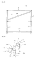
FIG. 16 is a perspective view illustrating an assembly shelf according to one embodiment of the invention. -
FIG. 17 is a perspective view illustrating another assembly shelf according to one embodiment of the invention. -
FIG. 18 is a view illustrating a middle shelf board removal operation. -
FIG. 19 is an exploded perspective view illustrating another coupling member. -
FIG. 20 is an exploded perspective view illustrating another coupling member. -
FIG. 21 is a perspective view illustrating a state in which the coupling member illustrated inFIG. 20 is fitted. -
FIG. 22 is a perspective view illustrating another coupling member. -
FIG. 23 is a perspective view illustrating another coupling member. -
FIG. 24 is a perspective view illustrating a state in which the coupling member illustrated inFIG. 23 is fitted. -
FIG. 25 is an enlarged front view illustrating a coupling member of an assembly shelf. -
FIG. 26 is an enlarged perspective view illustrating part of coupled assembly shelves. - A coupling member according to a first embodiment of the invention and a shelf board member that is attached using the same are described below with reference to
FIGS. 1 to 18 . Acoupling member 1 is fitted to apost 2, and supports oneshelf board member 31 within the half area of thecoupling member 1 in the diametrical direction when viewed from the front side (i.e., within an area indicated by X/2 inFIG. 15 (X indicates the dimension of thecoupling member 1 in the transverse direction (seeFIGS. 15 and16 )). Since thecoupling member 1 supports oneshelf board member 31 within the half area of thecoupling member 1 in the diametrical direction when viewed from the front side, the position of a middle shelf board member of an assembly shelf that includes a plurality of shelf board members arranged in the vertical direction can be changed (i.e., the middle shelf board member can be removed) without removing the other shelf board members. Moreover, another shelf board member can be coupled directly to the assembly shelf in the transverse direction. - As illustrated in
FIGS. 2 and4 , thecoupling member 1 includes two members 1a and 1b that are fitted to each other to hold thepost 2 from either side, each of the members 1a and 1b including a firsttapered section 16a (16b) that gradually increases in diameter in the downward direction, and a secondtapered section 17a (17b) that gradually slopes inward in the downward direction, and the firsttapered section 16a of the member 1a (one member) and the secondtapered section 17b of the member 1b (the other member) being disposed within the half area (X/2 inFIG. 15 ) of thecoupling member 1 in the diametrical direction when viewed from the front side when thecoupling member 1 is fitted to thepost 2. The diametrical direction of thecoupling member 1 when viewed from the front side refers to the diametrical direction that extends in the transverse direction when viewed from the front side. When thecoupling member 1 is fitted to thepost 2, the firsttapered section 16b of the member 1b and the secondtapered section 17a of the member 1 a are disposed within the other half area of thecoupling member 1 in the diametrical direction when viewed from the front side. Since the tapered sections of the member 1a and the member 1b are disposed within the half area of thecoupling member 1 in the diametrical direction when viewed from the front side, it is possible to remove a middle shelf board member. Note that sign a is assigned to one member, and sign b is assigned to the other member. - The first
tapered section 16a (16b) gradually increases in diameter with respect to the axial center of thepost 2 when thecoupling member 1 is fitted to thepost 2. Therefore, the expression "the firsttapered section 16a (16b) gradually increases in diameter" means that the firsttapered section 16a (16b) slopes so that the firsttapered section 16a (16b) is positioned away from the axial center of thepost 2 in the downward direction. The secondtapered section 17a (17b) gradually slopes inward with respect to the axial center of thepost 2 when viewed from the front side when thecoupling member 1 is fitted to thepost 2. Therefore, the expression "the secondtapered section 17a (17b) gradually slopes inward" means that the secondtapered section 17a (17b) slopes so that the secondtapered section 17a (17b) is positioned closer to the axial center of thepost 2 in the downward direction when viewed from the front side (i.e., the secondtapered section 17a (17b) slopes to diagonally intersect the transverse direction when viewed from the front side). The term "front side" used herein refers to the side indicated by F inFIG. 16 , of which the transverse direction is parallel to the shelf board member coupling direction. Note that the shelf board member coupling direction normally corresponds to the longitudinal direction of the shelf board member, but does not necessarily correspond to the longitudinal direction of the shelf board member. An acute angle is formed by the wall where the secondtapered section 17a (17b) is formed in a plan view (seeFIG. 7 ). This prevents a situation in which aflange 32 of athird engagement section 3 comes off from the secondtapered section 17a (17b). - The two members (i.e., the member 1a and the member 1b) that form the
coupling member 1 may have an identical shape and identical dimensions. In the first embodiment, the member 1a and the member 1b have an identical shape and identical dimensions (i.e., the member 1a is vertically rotated by 180 degrees when used as the member 1b, and vice versa). When the member 1a and the member 1b have an identical shape and identical dimensions, it suffices to use one mold when producing the member 1a and the member 1b, so that the production cost can be reduced. Note that the same description applies to the member 1a and the member 1b. - Each of the member 1a and the member 1b of the coupling member includes a
main body 11a (11b) that has an inner circumferential surface 142 (143) having a shape that corresponds to the shape of the side surface of thepost 2, andarm sections main body 11a (11b) in the diametrical direction (internal direction) of thepost 2. As illustrated inFIGS. 3 to 10 , the member 1a includes themain body 11a that has the concave innercircumferential surface 142 having a shape that corresponds to the shape of the side surface of thepost 2, twoarm sections 12a that are spaced apart from each other in the vertical direction, and extend from one side (i.e., the back side when viewed from the front side) of themain body 11a in the diametrical direction of thepost 2, and onearm section 13a that extends from the center area (in the vertical direction) of the other side (i.e., the front side when viewed from the front side) of themain body 11a in the diametrical direction of thepost 2. The member 1b includes themain body 11b that has the concave innercircumferential surface 143 having a shape that corresponds to the shape of the side surface of thepost 2, onearm section 13b that extends from the center area (in the vertical direction) of one side (i.e., the back side when viewed from the front side) of themain body 11b in the diametrical direction of thepost 2, and twoarm sections 12b that are spaced in the vertical direction, and extend from the other side (i.e., the front side when viewed from the front side) of themain body 11b in the diametrical direction of thepost 2. - When the
coupling member 1 is fitted to thepost 2, thearm section 13b of the member 1b is positioned between the twoarm sections 12a of the member 1a, and thearm section 13a of the member 1a is positioned between the twoarm sections 12b of the member 1b. Specifically, the arm sections of the one member and the arm sections of the other member are alternately disposed when thecoupling member 1 is fitted to thepost 2. - The
main body 11a (11b) includes the firsttapered section 16a (16b) that is in the shape of a concave plate that has a given height and a given width, and has an outer circumferential surface that has a given width and a given height and increases in diameter in the downward direction. The given width is not particularly limited, but may be almost equal to the diameter of thepost 2 when viewed from the side. This makes it possible to maintain strength, and firmly fit thecoupling member 1 to thepost 2. A sufficient tightening force can be obtained by setting the taper angle of the firsttapered section 16a (16b) to about 2 to 3 degrees. - An elongated protrusion 14a (14b) or a protrusion that engages the
post 2 is formed on the inner circumferential surface 142 (143) of themain body 11a (11b). The elongated protrusion 14a (14b) is an annular protrusion that is (partially) formed on the inner circumferential surface 142 (143) along the widthwise direction, and engages an annular or partiallyannular locking groove 22 of thepost 2. The vertical movement of thecoupling member 1 can be prevented by causing the elongated protrusion 14a (14b) to engage the lockinggroove 22. The protrusion may engage a locking hole (not illustrated in the drawings) formed in thepost 2. The locking hole is a hole having a bottom. - The
arm sections tapered section 17a (17b). Since thearm sections arm sections post 2 when viewed from the front side when thecoupling member 1 is fitted to thepost 2, the secondtapered section 17a (17b) can be formed within the other half area of thecoupling member 1 in the diametrical direction. - As illustrated in
FIG. 4 , the secondtapered section 17a (17b) of the member 1a (1b) has a rectangular planar surface that has a given length and a given width, and is observed when viewed from the front side. As illustrated inFIG. 7 , the secondtapered section 17a (17b) is a wall that is formed opposite to the main body by removing a center area (in the lengthwise direction) of a plate-shaped body (arm section) having a given thickness in the thickness direction. A sufficient tightening force can be obtained by setting the taper angle of the secondtapered section 17a (17b) to about 2 to 3 degrees. - Note that a
wall 18a (18b) formed on the side of themain body 11a (11b) by removing the center area (in the lengthwise direction) of the plate-shaped body having a given thickness in the thickness direction is positioned on the side of the main body relative to the secondtapered section 17b of the other member when thecoupling member 1 is fitted to thepost 2. According to this structure, when thecoupling member 1 is fitted to thepost 2, and thethird engagement section 3 of theshelf board member 31 is fitted to thecoupling member 1, only the firsttapered section 16a of the member 1a and the secondtapered section 17b of the member 1b come in contact with thethird engagement section 3, and thewall 18a (18b) does not hinder assembly. - As illustrated in
FIG. 9 , the firsttapered section 16a that slopes outward in the downward direction, and the secondtapered sections 17b that slope inward in the downward direction are observed on the right side of the axial center of thepost 2 when viewed from the front side when thecoupling member 1 is fitted to thepost 2. Since the secondtapered sections 17b that are observed when viewed from the front side are respectively formed on the arm sections that are spaced apart from each other in the vertical direction, the secondtapered sections 17b are spaced apart from each other, but form a continuous tapered shape. The secondtapered section 17b that is observed from the back side is formed on the center arm section. Thewall 18a that is observed between the secondtapered sections 17b when viewed from the front side is formed on the one member, and does not form a continuous tapered shape with the secondtapered sections 17b (i.e., forms a difference in level). The difference in level between the secondtapered sections 17b and thewall 18a is an allowance m (seeFIG. 9 ) that makes it possible to allow the members 1a and 1b to firmly hold thepost 2. When the allowance m is zero, the effect of allowing the members 1a and 1b to firmly hold thepost 2 significantly decreases. - A
recess 15a (15b) of thearm sections tapered section 17a (17b) and thewall 18a (18b) is a fifth tapered section that gradually slopes outward in the downward direction. The fifth tapered section corresponds to a sixth tapered section of thethird engagement section 3 of theshelf board member 31. Therefore, thecoupling member 1 can be firmly fitted to thepost 2 by fitting thethird engagement section 3 to thecoupling member 1. A sufficient tightening force can be obtained by setting the taper angle of the fifthtapered section 15a (15b) to about 2 to 3 degrees. - The
coupling member 1 is formed of a metal, a resin, or a composite thereof. It is preferable that thecoupling member 1 be formed of a resin since metal noise or the like does not occur during assembly, and assembly is facilitated. An engineering plastic (e.g., polyacetal resin, polyamide resin, acrylonitrile-butadiene-styrene copolymer resin (ABS resin), epoxy resin, phenol resin, or polycarbonate resin) may be used as the resin. These synthetic resins exhibit excellent impact resistance, abrasion resistance, and chemical resistance. The resin may include reinforcing fibers such as glass fibers or carbon fibers. - An assembly shelf according to the first embodiment is described below. An
assembly shelf 10 according to the first embodiment includes thecoupling member 1 that includes the two members. Theassembly shelf 10 includes thepost 2, thecoupling member 1, and theshelf board member 31. Oneshelf board member 31 is secured on fourposts 2 using fourcoupling members 1. The three-stage assembly shelf 10 illustrated inFIG. 16 includes threeshelf board members 31, fourposts 2, and twelvecoupling members 1. Note that the twelvecoupling members 1 utilize twelve pairs of members (i.e., twenty-four members). - The
assembly shelf 10 according to the first embodiment includes fourposts 2 on which thecoupling member 1 is secured, and theshelf board member 31 that includes thethird engagement sections 3 that are respectively formed at the four corners of theshelf board member 31, each of thethird engagement sections 3 including a thirdtapered section 33 that comes in contact with the firsttapered section 16a (16b) of the member 1a of thecoupling member 1, a fourthtapered section 32 that comes in contact with the secondtapered sections 17b of the member 1b of thecoupling member 1, and a sixthtapered section 36 that comes in contact with the fifthtapered section 15a (15b) formed on thearm sections 12a (12b) and 13a (13b) of thecoupling member 1, theshelf board member 31 being secured by fitting eachthird engagement section 3 to eachcoupling member 1, and theshelf board member 31 being disposed between the axial center of onepost 2 among the fourposts 2 and the axial center of anotherpost 2 among the fourposts 2 when viewed from the front side. Note that the fifthtapered section 15a (15b) of thecoupling member 1 and the sixthtapered section 36 of thethird engagement section 3 are optional elements. - A plurality of annular or partially annular locking grooves may be formed in the
post 2 in the longitudinal direction at regular or irregular intervals. The cross-sectional shape of thepost 2 is not particularly limited. Thepost 2 may have a circular cross-sectional shape, an elliptical cross-sectional shape, a quadrangular cross-sectional shape, a rhombic cross-sectional shape, a cross-sectional shape in the shape of the letter "X", a cross-sectional shape in the shape of the letter "H", or the like. The partially annular locking groove may be a groove that is linearly formed in the outer circumferential surface of thepost 2 so that the depth of the groove increases at the center of the groove, and decreases toward the edge (end) of the groove. - The
shelf board member 31 has a configuration in which thethird engagement section 3 that engages thecoupling member 1 is formed at each (approximate) corner. The term "each corner" refers to each end of theshelf board member 32 in the lateral direction. This makes it possible to install theassembly shelf 10 in a stable manner due to an increase in installation area formed by the four posts. The main part of the shelf board member may have a board-like structure or a net-like structure. Theshelf board member 31 normally has a rectangular shape in a plane view. - As illustrated in
FIGS. 11 to 13 , thethird engagement section 3 of theshelf board member 31 includes an engagementmain body 35 that has an inner circumferential surface having a shape that corresponds to the shape of the side surface of thecoupling member 1, and aflange 34 that extends inward from each end of the engagementmain body 35. The thirdtapered section 322 is formed on the inner circumferential surface (inner wall surface) 33 of ahollow section 311, and a fourthtapered section 321 is formed on aside 32 of theflange 34 that faces the third tapered section. As illustrated inFIGS. 11 and13 , the fourthtapered section 321 is observed when viewed from the front side (Z2-Z2 inFIG. 11 ), and has a shape that corresponds to the shape of the secondtapered section 17a (17b) of thecoupling member 1. The thirdtapered section 322 has a shape that corresponds to the shape of the firsttapered section 16a (16b) of the coupling member 1 (i.e., a recess that increases in diameter in the downward direction in one embodiment). - An
inner side surface 36 of theflange 34 forms a tapered section (sixth tapered section) that gradually slopes outward in the downward direction. The sixthtapered section 36 corresponds to the fifthtapered section 15a (15b) of thecoupling member 1. Since the sixth tapered section strongly presses thearm sections coupling member 1 against the post by fitting thethird engagement section 3 to thecoupling member 1, thecoupling member 1 can be firmly fitted to thepost 2. A sufficient tightening force can be obtained by setting the taper angle of the sixthtapered section 36 to about 2 to 3 degrees. - An acute angle is formed by the
flange 34 on the side of the third tapered section in a plane view. Therefore, removal of thethird engagement section 3 can be prevented due to engagement with the wall (second taperedsection 17a (17b)) that also forms an acute angle. - An example of a method that secures the
shelf board member 31 on theposts 2 is described below. A lowermost shelf board member 31b is secured on theposts 2 via thecoupling members 1. More specifically, thecoupling member 1 is attached to thepost 2 at a given position in the height direction. When attaching thecoupling member 1, the two members are fitted to thepost 2 to hold thepost 2 from either side. The two members are fitted to thepost 2 so that the elongated protrusion 14a (14b) of thecoupling member 1 is fitted into the lockinggroove 22 of thepost 2. The vertical movement of thecoupling member 1 is prevented by fitting the elongated protrusion 14a (14b) of thecoupling member 1 into the lockinggroove 22 of thepost 2. Thecoupling member 1 is attached to eachpost 2. Next, eachthird engagement section 3 of the shelf board member 31b is fitted to eachcoupling member 1 from above (FIG. 15A ). The thirdtapered section 322 of theshelf board member 31 comes in contact with the firsttapered section 16a of the member 1a of thecoupling member 1, and presses the member 1a against the post 2 (direction A inFIG. 15A ), and the fourthtapered section 321 of theshelf board member 31 comes in contact with the secondtapered section 17b of the member 1b of thecoupling member 1, and presses the member 1b against the member 1a (direction B inFIG. 15A ), so that the two members of thecoupling member 1 hold the post 2 (FIG. 15B). Specifically, theshelf board member 31 does not come in contact with thepost 2, and is supported by thecoupling member 1. Thecoupling member 1 is firmly secured on thepost 2 by fitting thethird engagement section 3 of theshelf board member 31 to thecoupling member 1 in the downward direction. A middle shelf member 31a and an uppermostshelf board member 31 are then secured on theposts 2. The middle shelf member 31a and the uppermostshelf board member 31 may be secured in an arbitrary order. Specifically, the uppermostshelf board member 31 may be secured after securing the middle shelf member 31 a, or the middle shelf member 31a may be secured after securing the uppermostshelf board member 31. A related-art assembly shelf does not allow the middle shelf member 31 a to be secured after securing the uppermostshelf board member 31. In contrast, the assembly shelf according to the first embodiment allows the middle shelf member 31 a to be secured after securing the uppermostshelf board member 31. This enhances the degree of freedom of the working process, and facilitates the assembly work. - When the
assembly shelf 10 illustrated inFIG. 16 is referred to as an assembly shelf unit (normally a multi-stage assembly shelf unit), theshelf board member 31 is disposed between the axial center of onepost 2 among the fourposts 2 and the axial center of anotherpost 2 among the fourposts 2 when viewed from the front side (seeFIGS. 15 and16 ). As illustrated inFIG. 25 , the length (l2) of one side of theshelf board member 31 when viewed from the front side is equal to or slightly less than the distance (l1) between the axial center Y of theleft post 2 and the axial center Y of theright post 2. Specifically, theshelf board member 31 is supported within the half area of thecoupling member 1 in the diametrical direction when viewed from the front side. When the length (l2) of one side of theshelf board member 31 when viewed from the front side is slightly less than the distance (l1) between the axial center Y of theleft post 2 and the axial center Y of the right post 2 (seeFIG. 25 ), the end of theshelf board member 31 does not come in contact with the end of anothershelf board member 31 when coupling twoassembly shelves 10, so that theassembly shelves 10 can be easily coupled (assembled). The end-to-end distance between two coupled shelf board members 31 (i.e., a value twice the distance between the axial center of thepost 2 and the end face of the shelf board member 31) (n inFIG. 26 ) is preferably set to 5 mm or less, and more preferably 2 mm or less in order to prevent a situation in which small articles placed on theshelf board member 31 fall off from theshelf board member 31. In the first embodiment, the end of theshelf board member 31 refers to the end of thethird engagement section 3. Therefore, each end of theshelf board member 31 is not positioned outside the axial center of eachpost 2 when viewed from the front side. Note that the axial center Y refers to the center of thepost 2 that extends in the vertical direction when viewed from the front side. - Each end of the
shelf board member 31 is disposed within the half area of thecoupling member 1 in the diametrical direction when viewed from the front side. When coupling twoassembly shelves 10 in the longitudinal direction, the right and leftshelf board members 31 can be secured on a single post 2 (seeFIGS. 14 and17 ) by thus utilizing the half area of the post 2 (i.e., the half area of the coupling member 1) for securing oneshelf board member 31. - The
shelf board members 31 are coupled in the horizontal direction (seeFIG. 17 ) as described below. Specifically, thethird engagement section 3 of another shelf board member that is coupled to theassembly shelf 10 in the longitudinal direction is fitted within the other half area of thecoupling member 1 in the diametrical direction when viewed from the front side to couple twoshelf board members 31 via asingle post 2. Anassembly shelf 20 is thus obtained. As illustrated inFIG. 17 , theassembly shelf 20 is a double assembly shelf in which theshelf board members 31 are provided on either side of asingle post 2. Theassembly shelf 20 differs from theassembly shelf 10 as to the usage of themiddle post 2. As illustrated inFIGS. 16 and17 , the coupling targetshelf board member 3 is secured within the other half area of thecoupling member 1 in the diametrical direction. Theshelf board members 31 additionally used for theassembly shelf 20 and their installation method are the same as those described above in connection with theassembly shelf 10. - A case of removing the middle shelf board member 31a of the
assembly shelf FIGS. 16 , and18 . When removing the middle shelf board member 31 a illustrated inFIG. 16 , the middle shelf board member 31a is moved upward to some extent. An obstacle that may hinder the movement of the middle shelf board member 31a is not present in a space S above the middle shelf board member 3b, and a sufficient clearance is present between thepost 2 and thethird engagement section 3 of the shelf board member 31 a at a position where thecoupling member 1 is not secured on thepost 2. When the middle shelf board member 31a has been moved upward to some extent, the middle shelf board member 31a is tilted along the longitudinal direction (seeFIG. 18 ). The middle shelf board member 31a is tilted so that the horizontal dimension of the tilted middle shelf board member 31a is smaller than the distance between theposts 2 of theassembly shelf 10. The tilted middle shelf board member 31 a is then moved forward from theassembly shelf 10. The middle shelf board member 31 a can thus be removed. After removing the middle shelf board member 31 a, thecoupling member 1 may be secured at a different position, and the middle shelf board member 31a may be secured again. The position of the middle shelf board member 31a can thus be changed. - The middle shelf board member 31a can be secured again by performing the above steps in the reverse order. The
assembly shelves - An assembly shelf according to a second embodiment of the invention is described below with reference to
FIG. 19 . InFIG. 19 , the same elements as those illustrated inFIGS. 1 and 2 are indicated by identical signs, and description thereof is omitted. The following description mainly focuses on the differences from theassembly shelf 10. An assembly shelf 10a according to the second embodiment mainly differs from theassembly shelf 10 as to the shape of the arm section of a coupling member 1A. - The coupling member 1A of the assembly shelf 10a includes a member 1c (one member) and a member 1d (the other member), the member 1c including a main body 11c that has a concave inner circumferential surface having a shape that corresponds to the shape of the side surface of the post 2, an arm section 12c that extends in the diametrical direction (inner side) of the post 2 from the upper half of one side (i.e., the back side when viewed from the front side) of the main body 11c, and an arm section 13c that extends in the diametrical direction (inner side) of the post 2 from the lower half of the other side (i.e., the front side when viewed from the front side) of the main body 11c, and the member 1d including a main body 11d that has a concave inner circumferential surface having a shape that corresponds to the shape of the side surface of the post 2, an arm section 13d that extends in the diametrical direction (inner side) of the post 2 from the lower half of one side (i.e., the back side when viewed from the front side) of the main body 11d, and an arm section 12d that extends in the diametrical direction (inner side) of the post 2 from the upper half of the other side (i.e., the front side when viewed from the front side) of the main body 11d.
- When the coupling member 1A is fitted to the
post 2, the arm section 13d of the member 1d is positioned under the arm section 12c of the member 1c, and the arm section 13c of the member 1c is positioned under the arm section 12d of the member 1d. - The fitting structure of the assembly shelf 10a formed by the coupling member 1A, the
post 2, and theshelf board member 31 achieves the same effects as those achieved by the fitting structure of theassembly shelf 10. The assembly shelf 10a enables a middle shelf board removal operation in the same manner as theassembly shelf 10. Another assembly shelf can be coupled to the assembly shelf 10a in the lateral direction. - Note that the coupling member may be configured so that three arm sections of one member and three arm sections of the other member may be alternately disposed when the coupling member is fitted to the post, for example, instead of employing the configuration according to the first embodiment (i.e., one arm section of one member and two arm sections of the other member are alternately disposed) or the configuration according to the second embodiment (i.e., one arm section of one member and one arm section of the other member are disposed side by side).
- An assembly shelf according to a third embodiment of the invention is described below with reference to
FIGS. 20 and 21 . InFIGS. 20 and 21 , the same elements as those illustrated inFIGS. 1 and 2 are indicated by identical signs, and description thereof is omitted. The following description mainly focuses on the differences from theassembly shelf 10. Anassembly shelf 10b according to the third embodiment mainly differs from theassembly shelf 10 as to the shape of a post 2a, the shape of a lockinggroove 22a, the shape of acoupling member 1B, and the shape of the third engagement section of the shelf board member. - The post 2a of the
assembly shelf 10b is in the shape of a quadrangular prism having a quadrangular cross section. The lockinggroove 22a is formed in aleft side 221 and aright side 222 of the post 2a in the shape of a quadrangular prism (i.e., is not formed in the front side and the back side of the post 2a). - A
main body 11e (11f) includes a first tapered section 16e (16f) that is in the shape of a planar plate that has a given height and a given width, and has an outer circumferential surface that has a given width and a given height and slopes outward in the downward direction. The given width is the same as the width of the post 2a. Therefore, thecoupling member 1B can be fitted to the post 2a without forming a clearance. Anelongated protrusion 14e that engages the lockinggroove 22a of the post 2a and extends in the horizontal direction is formed on the back side of themain body 11e (11f). This ensures that theelongated protrusion 14e reliably engages the lockinggroove 22a of the post 2a. - A third engagement section 3f of the
shelf board member 31 has ahollow section 311 that has a volume that accommodates about half of thecoupling member 1 B in the longitudinal direction of the shelf board member. Therefore, the third engagement section 3f can be fitted to thecoupling member 1B without forming a clearance. - The fitting structure of the
assembly shelf 10b formed by thecoupling member 1B, the post 2a, and theshelf board member 31 achieves the same effects as those achieved by the fitting structure of theassembly shelf 10. Theassembly shelf 10b enables a middle shelf board removal operation in the same manner as theassembly shelf 10. Another assembly shelf can be coupled to theassembly shelf 10b in the lateral direction. - An assembly shelf according to a fourth embodiment of the invention is described below with reference to
FIG. 22 . InFIG. 22 , the same elements as those illustrated inFIG. 20 are indicated by identical signs, and description thereof is omitted. The following description mainly focuses on the differences from theassembly shelf 10b. An assembly shelf 10c according to the fourth embodiment mainly differs from theassembly shelf 10b as to the shape of a lockinggroove 22b. - In the assembly shelf 10c, the locking
groove 22b is formed in each side of a post 2b in the shape of a quadrangular prism. - The fitting structure of the assembly shelf 10c formed by the
coupling member 1B, the post 2b, and theshelf board member 31 achieves the same effects as those achieved by the fitting structure of theassembly shelf 10b. The assembly shelf 10c enables a middle shelf board removal operation in the same manner as theassembly shelf 10b. Another assembly shelf can be coupled to the assembly shelf 10c in the lateral direction. - An assembly shelf according to a fifth embodiment of the invention is described below with reference to
FIGS. 23 and24 . InFIGS. 23 and24 , the same elements as those illustrated inFIGS. 20 and 21 are indicated by identical signs, and description thereof is omitted. The following description mainly focuses on the differences from theassembly shelf 10b. Anassembly shelf 10d according to the fifth embodiment mainly differs from theassembly shelf 10b as to the shape of apost 2c, the shape of a coupling member 1C, and the shape of the third engagement section of the shelf board member. - The
post 2c of theassembly shelf 10d is in the shape of a quadrangular prism having a rhombic cross section. A lockinggroove 22c is formed in each side of apost 2c in the shape of a quadrangular prism. - A main body 11g (11h) of the
assembly shelf 10d includes a first tapered section that has a given height and a given width, has a hollow section having a triangular cross-sectional shape that corresponds to the external shape of thepost 2c, and has an outer circumferential surface that has a given width and a given height and slopes outward in the downward direction. The given width is the same as the width of thepost 2c. Therefore, the coupling member 1C can be fitted to thepost 2c without forming a clearance. An elongated protrusion 14g that engages the lockinggroove 22c of thepost 2c and extends in the horizontal direction is formed on the back side of the main body 11g (11h). Therefore, the elongated protrusion 14g reliably engages the lockinggroove 22c of thepost 2c. - A
third engagement section 3g of theshelf board member 31 has ahollow section 311 that has a volume that accommodates about half of the coupling member 1C in the longitudinal direction of the shelf board member. Therefore, thethird engagement section 3g can be fitted to the coupling member 1C without forming a clearance. - The fitting structure of the
assembly shelf 10d formed by the coupling member 1C, thepost 2c, and theshelf board member 31 achieves the same effects as those achieved by the fitting structure of theassembly shelf 10b. Theassembly shelf 10d enables a middle shelf board removal operation in the same manner as theassembly shelf 10b. Another assembly shelf can be coupled to theassembly shelf 10d in the lateral direction. - The assembly shelves according to the embodiments of the invention may be used as a storage shelf in an office, home, warehouse, store, or the like, or may be used as a display shelf in a store, and implements easy assembly and disassembly.
-
- 1 Coupling member
- 1a One member
- 1b The other member
- 2, 2a, 2b, 2c Post
- 3 Third engagement section
- 10, 10a, 10b, 10c, 10d, 20 Assembly shelf
- 1a (11b) Main body of coupling member
- 12a (12b) Arm section
- 13a (13b) Arm section
- 14a (14b) Protrusion
- 16a (16b) First tapered section
- 17a (17b) Second tapered section
- 322 Third tapered section
- 321 Fourth tapered section
- 22, 22a, 22b, 22c Locking groove
- 31 Shelf board member
Claims (13)
- A coupling member that is fitted to a post, and supports one shelf board member within a half area of the coupling member in a diametrical direction when viewed from a front side, the coupling member comprising:two members that are fitted to each other to hold the post from either side,each of the two members including a first tapered section that gradually increases in diameter in a downward direction, and a second tapered section that gradually slopes inward in the downward direction, andthe first tapered section of one member among the two members and the second tapered section of another member among the two members being disposed within the half area of the coupling member in the diametrical direction when viewed from the front side when the coupling member is fitted to the post.
- The coupling member according to claim 1,
wherein each of the two members includes a main body that has an inner circumferential surface having a shape that corresponds to a shape of a side surface of the post, and arm sections that extend from either side of the main body in a diametrical direction of the post, and
the first tapered section is formed by an outer circumferential surface of the main body, and the second tapered section is formed by each of the arm sections. - The coupling member according to claim 1,
wherein the arm section or arm sections of the one member and the arm section or arm sections of the other member are alternately disposed when the coupling member is fitted to the post. - The coupling member according to claim 1, further comprising an elongated protrusion or a protrusion that is formed on the inner circumferential surface of the main body, and engages the post.
- The coupling member according to claim 1, the coupling member being formed of a metal, a resin, or a composite thereof.
- The coupling member according to claim 1, wherein the two members have an identical shape and identical dimensions.
- An assembly shelf comprising the coupling member according to any one of claims 1 to 6.
- An assembly shelf comprising:four posts on which the coupling member according to any one of claims 1 to 6 is respectively secured, a plurality of locking grooves or locking holes being formed in each of the four posts in a longitudinal direction at regular or irregular intervals; anda shelf board member, third engagement sections being respectively formed at four corners of the shelf board member, each of the third engagement sections including a third tapered section that comes in contact with the first tapered section of the one member of the coupling member, and a fourth tapered section that comes in contact with the second tapered section of the other member of the coupling member,the shelf board member being secured by fitting the third engagement section to the coupling member, and the shelf board member being disposed between an axial center of one post among the four posts and an axial center of another post among the four posts when viewed from a front side.
- The assembly shelf according to claim 8, wherein the plurality of locking grooves are annular or partially annular.
- The assembly shelf according to claim 8, wherein each of the third engagement sections includes an engagement main body that has an inner circumferential surface having a shape that corresponds to a shape of a side surface of the coupling member, and a flange that extends inward from each end of the engagement main body.
- The assembly shelf according to claim 8, wherein the third tapered section has an inner circumferential shape that corresponds to a shape of a side surface of the coupling member, and corresponds to the first tapered section of the one member.
- The assembly shelf according to claim 8, wherein the fourth tapered section is formed on a side of a flange of the third engagement section that faces the third tapered section, and corresponds to the second tapered section of the other member.
- The assembly shelf according to claim 8, wherein the third tapered section of the shelf board member presses the one member of the coupling member against the post, and the fourth tapered section of the shelf board member presses the other member of the coupling member against the one member, so that the two members of the coupling member hold the post.
Applications Claiming Priority (1)
| Application Number | Priority Date | Filing Date | Title |
|---|---|---|---|
| PCT/JP2010/051621 WO2011096063A1 (en) | 2010-02-04 | 2010-02-04 | Coupling member, and assembled rack provided with same |
Publications (3)
| Publication Number | Publication Date |
|---|---|
| EP2532902A1 true EP2532902A1 (en) | 2012-12-12 |
| EP2532902A4 EP2532902A4 (en) | 2013-06-19 |
| EP2532902B1 EP2532902B1 (en) | 2014-06-25 |
Family
ID=44355091
Family Applications (1)
| Application Number | Title | Priority Date | Filing Date |
|---|---|---|---|
| EP10845199.8A Active EP2532902B1 (en) | 2010-02-04 | 2010-02-04 | Coupling member, and assembled rack provided with same |
Country Status (7)
| Country | Link |
|---|---|
| US (1) | US8678207B2 (en) |
| EP (1) | EP2532902B1 (en) |
| JP (1) | JP5522750B2 (en) |
| KR (1) | KR101677788B1 (en) |
| CN (1) | CN102741566B (en) |
| AU (1) | AU2010344809B2 (en) |
| WO (1) | WO2011096063A1 (en) |
Families Citing this family (29)
| Publication number | Priority date | Publication date | Assignee | Title |
|---|---|---|---|---|
| WO2007005728A2 (en) * | 2005-07-01 | 2007-01-11 | L & P Property Management Company | Adjustable shelving system |
| DE102011109848A1 (en) * | 2011-08-09 | 2013-02-14 | Airbus Operations Gmbh | Basic body, scaffold system and manufacturing method for such a body |
| US9192250B2 (en) * | 2012-12-29 | 2015-11-24 | Scott D. Maurer | Shelf assembly particularly suitable for wire grid rack systems having racks at fixed vertical spacings |
| CN105025753B (en) * | 2013-03-05 | 2018-01-02 | 河淳株式会社 | Connecting component and assembly frame using the connecting component |
| US9249818B2 (en) * | 2013-08-30 | 2016-02-02 | Pro-Mart Industries, Inc. | Shelving connector and method of manufacture |
| CN104273945A (en) * | 2013-11-07 | 2015-01-14 | 刘镇彪 | rack device |
| US10154739B2 (en) | 2013-12-02 | 2018-12-18 | Retail Space Solutions Llc | Universal merchandiser and methods relating to same |
| USD801734S1 (en) | 2014-12-01 | 2017-11-07 | Retail Space Solutions Llc | Shelf management parts |
| TW201600688A (en) * | 2014-04-15 | 2016-01-01 | 阿札德 沙包簡 | Shelving connector |
| ITMI20140159U1 (en) * | 2014-05-02 | 2015-11-02 | Terry Store Age S P A | MODULAR SHELVING WITH HIGH FLEXIBILITY OF USE |
| CN106794047A (en) * | 2014-07-29 | 2017-05-31 | 大卫·詹姆斯·库伯 | shelving system |
| US9468294B2 (en) * | 2015-02-03 | 2016-10-18 | Bestmate International Developing Co., Ltd. | Structure of expandable corrugated storage shelf system |
| US9468292B2 (en) * | 2015-03-09 | 2016-10-18 | Target Brands, Inc. | Shelving connector and associated storage system and method |
| USD784797S1 (en) | 2015-03-09 | 2017-04-25 | Target Brands, Inc. | Shelving connector |
| US20170065078A1 (en) * | 2015-09-04 | 2017-03-09 | Pro-Mart Industries, Inc. | Shelving connector |
| US20170224106A1 (en) * | 2016-02-05 | 2017-08-10 | Pro-Mart Industries, Inc. | Shelving connector |
| US10959540B2 (en) | 2016-12-05 | 2021-03-30 | Retail Space Solutions Llc | Shelf management system, components thereof, and related methods |
| WO2018200997A1 (en) | 2017-04-27 | 2018-11-01 | Retail Space Solutions Llc | Shelf-mounted tray and methods relating to same |
| US10058174B1 (en) * | 2017-05-02 | 2018-08-28 | MALZINE Co. Ltd. | Shelf structure |
| US10080437B1 (en) * | 2017-07-13 | 2018-09-25 | MALZINE Co. Ltd. | Connector for shelf assembly |
| US20190183246A1 (en) * | 2017-12-14 | 2019-06-20 | Marijan BERNIC | Shelving system |
| CH717061A1 (en) * | 2020-01-23 | 2021-07-30 | Visplay Int Ag | Structure system for the modular construction of shelves and shelves. |
| CN115399584B (en) * | 2021-05-28 | 2023-08-29 | 盈太企业股份有限公司 | Combined rack |
| DE202022101188U1 (en) * | 2022-03-03 | 2022-07-13 | Zarges Gmbh | shelving system |
| TW202412674A (en) * | 2022-09-16 | 2024-04-01 | 盈太企業股份有限公司 | Combined type shelf |
| US11700940B1 (en) * | 2022-09-22 | 2023-07-18 | Protrend Co., Ltd. | Combination shelf with dual-pole vertical columns |
| CN220607756U (en) * | 2023-07-18 | 2024-03-19 | 深圳市通之泰科技有限公司 | Parallel-connectable storage racks |
| US11930922B1 (en) | 2023-11-08 | 2024-03-19 | Howard Levine | Expandable stand-alone shelving assembly |
| US12408782B1 (en) * | 2024-08-21 | 2025-09-09 | Gaatu Inc | Size-adjustable net frame and wardrobe stand |
Family Cites Families (27)
| Publication number | Priority date | Publication date | Assignee | Title |
|---|---|---|---|---|
| US3523508A (en) * | 1968-05-02 | 1970-08-11 | Louis Maslow | Adjustable shelving |
| JPS6035769Y2 (en) * | 1981-06-09 | 1985-10-24 | 寺尾工業株式会社 | clamp |
| US4582001A (en) * | 1984-02-27 | 1986-04-15 | Nashville Wire Products | Shelf connector assembly |
| US4656952A (en) * | 1985-11-04 | 1987-04-14 | Schweizer Martin F | Adjustable shelving system |
| US4750626A (en) * | 1986-01-17 | 1988-06-14 | United Steel & Wire Company | Removable conical corner structure for shelving |
| JPH0357990A (en) | 1989-07-26 | 1991-03-13 | Matsushita Electric Works Ltd | Human body detector |
| JPH0630740Y2 (en) * | 1989-08-29 | 1994-08-17 | 矢崎化工株式会社 | Shelf pillars made of synthetic resin-coated metal tubes |
| EP0451012A1 (en) * | 1990-03-27 | 1991-10-09 | Cidelcem | Shelving system with detachable shelves |
| JP3057990B2 (en) | 1993-12-06 | 2000-07-04 | 日本電気株式会社 | Semiconductor integrated circuit device |
| JP3054076U (en) * | 1998-05-15 | 1998-11-17 | 志雄 林 | Assembling shelf |
| JP2000046021A (en) * | 1998-07-30 | 2000-02-15 | Teramoto Corp | Telescopic rod and handled tool using this telescopic rod |
| JP3057990U (en) | 1998-09-25 | 1999-06-08 | 株式会社藤栄 | Shelf locking structure |
| US6068143A (en) * | 1998-11-24 | 2000-05-30 | Wang; Chang Chou | Devices for fastening shelves to upright support rods |
| US6044988A (en) * | 1999-05-04 | 2000-04-04 | Yang; Hsin-Chen | Fitting structure of modular rack |
| JP3469161B2 (en) * | 2000-04-13 | 2003-11-25 | エレクター株式会社 | Assembled shelves |
| JP3387896B2 (en) * | 2000-08-17 | 2003-03-17 | 盈太企業有限公司 | Assembling rack structure |
| US6364138B1 (en) * | 2000-08-28 | 2002-04-02 | Protrend Co., Ltd. | Sectional rack |
| CN2635973Y (en) * | 2003-08-11 | 2004-08-25 | 深圳龙岗区龙岗回龙埔键兴钢具厂 | Semi-ring shape conic board supporting structure |
| US7093728B2 (en) * | 2003-12-31 | 2006-08-22 | Po-Ju Chen | Support stand for shelf |
| JP3104160U (en) | 2004-03-23 | 2004-09-02 | 柯金山 | Storage shelf structure |
| US7543540B2 (en) | 2005-04-21 | 2009-06-09 | Fontage Co., Ltd. | Assembly structure |
| CN2916223Y (en) * | 2006-01-23 | 2007-06-27 | 黄吉璁 | A bracket positioning device |
| CN201015484Y (en) * | 2007-01-16 | 2008-02-06 | 黄利旭 | Improved Structure of Laminates of Pillar Sleeve Combination Frame |
| CN201267294Y (en) * | 2008-08-15 | 2009-07-08 | 李国章 | Goods shelf |
| US8016140B2 (en) * | 2008-12-24 | 2011-09-13 | Ching-Chen Hsieh | Combination shelf whose support boards can be increased |
| WO2010074189A1 (en) * | 2008-12-24 | 2010-07-01 | 河淳株式会社 | Rack assembly |
| JP3149658U (en) | 2008-12-25 | 2009-04-09 | 謝景程 | Frame structure |
-
2010
- 2010-02-04 JP JP2011552617A patent/JP5522750B2/en active Active
- 2010-02-04 US US13/576,454 patent/US8678207B2/en active Active
- 2010-02-04 EP EP10845199.8A patent/EP2532902B1/en active Active
- 2010-02-04 KR KR1020127020084A patent/KR101677788B1/en active Active
- 2010-02-04 AU AU2010344809A patent/AU2010344809B2/en active Active
- 2010-02-04 WO PCT/JP2010/051621 patent/WO2011096063A1/en not_active Ceased
- 2010-02-04 CN CN201080063160.0A patent/CN102741566B/en active Active
Non-Patent Citations (2)
| Title |
|---|
| No further relevant documents disclosed * |
| See also references of WO2011096063A1 * |
Also Published As
| Publication number | Publication date |
|---|---|
| CN102741566B (en) | 2015-09-23 |
| KR101677788B1 (en) | 2016-11-18 |
| US20130026122A1 (en) | 2013-01-31 |
| AU2010344809A1 (en) | 2012-08-30 |
| WO2011096063A1 (en) | 2011-08-11 |
| AU2010344809B2 (en) | 2013-11-07 |
| KR20120139687A (en) | 2012-12-27 |
| EP2532902A4 (en) | 2013-06-19 |
| CN102741566A (en) | 2012-10-17 |
| JPWO2011096063A1 (en) | 2013-06-10 |
| JP5522750B2 (en) | 2014-06-18 |
| EP2532902B1 (en) | 2014-06-25 |
| US8678207B2 (en) | 2014-03-25 |
Similar Documents
| Publication | Publication Date | Title |
|---|---|---|
| EP2532902B1 (en) | Coupling member, and assembled rack provided with same | |
| EP2965655B1 (en) | Assembly shelf with coupling member | |
| US8505750B2 (en) | Assembly shelf | |
| JP5580106B2 (en) | Coupling member and assembly shelf provided with the same | |
| JP5605806B2 (en) | Assembly shelf and linked assembly shelf | |
| EP3566852B1 (en) | Blow-molded rib structure | |
| US20160007770A1 (en) | Store frames tooth profiles | |
| CN105491917A (en) | Groove and tongue system for a shelving wall of a shelving system | |
| CN102777868B (en) | Display device and manufacture mould of backlight module, back plate assembly and splicing parts of display device | |
| JP6013231B2 (en) | Assembly shelf | |
| US20140332647A1 (en) | Coupling device | |
| TWI492728B (en) | Coupling member and assembly shelf including the same | |
| CN205030783U (en) | Bookshelf is intensive | |
| CN216535954U (en) | Mounting structure of operation panel bottom plate and stand and have its medical shallow | |
| CN211135310U (en) | Novel linear calibration of steel wire device | |
| JP2013024021A (en) | System floor | |
| PL10105S2 (en) | Connection profile of load-bearing structures and frames | |
| KR20120006333U (en) | Supporting device of plate |
Legal Events
| Date | Code | Title | Description |
|---|---|---|---|
| PUAI | Public reference made under article 153(3) epc to a published international application that has entered the european phase |
Free format text: ORIGINAL CODE: 0009012 |
|
| 17P | Request for examination filed |
Effective date: 20120831 |
|
| AK | Designated contracting states |
Kind code of ref document: A1 Designated state(s): AT BE BG CH CY CZ DE DK EE ES FI FR GB GR HR HU IE IS IT LI LT LU LV MC MK MT NL NO PL PT RO SE SI SK SM TR |
|
| DAX | Request for extension of the european patent (deleted) | ||
| A4 | Supplementary search report drawn up and despatched |
Effective date: 20130522 |
|
| RIC1 | Information provided on ipc code assigned before grant |
Ipc: F16B 12/28 20060101AFI20130515BHEP Ipc: A47F 5/00 20060101ALI20130515BHEP Ipc: F16B 9/02 20060101ALI20130515BHEP Ipc: A47B 57/54 20060101ALI20130515BHEP Ipc: A47F 5/10 20060101ALI20130515BHEP Ipc: F16B 7/14 20060101ALI20130515BHEP Ipc: F16B 12/52 20060101ALI20130515BHEP Ipc: F16B 2/14 20060101ALI20130515BHEP Ipc: A47B 47/02 20060101ALI20130515BHEP |
|
| GRAP | Despatch of communication of intention to grant a patent |
Free format text: ORIGINAL CODE: EPIDOSNIGR1 |
|
| INTG | Intention to grant announced |
Effective date: 20140205 |
|
| GRAS | Grant fee paid |
Free format text: ORIGINAL CODE: EPIDOSNIGR3 |
|
| GRAA | (expected) grant |
Free format text: ORIGINAL CODE: 0009210 |
|
| AK | Designated contracting states |
Kind code of ref document: B1 Designated state(s): AT BE BG CH CY CZ DE DK EE ES FI FR GB GR HR HU IE IS IT LI LT LU LV MC MK MT NL NO PL PT RO SE SI SK SM TR |
|
| REG | Reference to a national code |
Ref country code: GB Ref legal event code: FG4D |
|
| REG | Reference to a national code |
Ref country code: CH Ref legal event code: EP |
|
| REG | Reference to a national code |
Ref country code: AT Ref legal event code: REF Ref document number: 674896 Country of ref document: AT Kind code of ref document: T Effective date: 20140715 |
|
| REG | Reference to a national code |
Ref country code: IE Ref legal event code: FG4D |
|
| REG | Reference to a national code |
Ref country code: DE Ref legal event code: R096 Ref document number: 602010017127 Country of ref document: DE Effective date: 20140807 |
|
| PG25 | Lapsed in a contracting state [announced via postgrant information from national office to epo] |
Ref country code: CY Free format text: LAPSE BECAUSE OF FAILURE TO SUBMIT A TRANSLATION OF THE DESCRIPTION OR TO PAY THE FEE WITHIN THE PRESCRIBED TIME-LIMIT Effective date: 20140625 Ref country code: FI Free format text: LAPSE BECAUSE OF FAILURE TO SUBMIT A TRANSLATION OF THE DESCRIPTION OR TO PAY THE FEE WITHIN THE PRESCRIBED TIME-LIMIT Effective date: 20140625 Ref country code: NO Free format text: LAPSE BECAUSE OF FAILURE TO SUBMIT A TRANSLATION OF THE DESCRIPTION OR TO PAY THE FEE WITHIN THE PRESCRIBED TIME-LIMIT Effective date: 20140925 Ref country code: GR Free format text: LAPSE BECAUSE OF FAILURE TO SUBMIT A TRANSLATION OF THE DESCRIPTION OR TO PAY THE FEE WITHIN THE PRESCRIBED TIME-LIMIT Effective date: 20140926 Ref country code: LT Free format text: LAPSE BECAUSE OF FAILURE TO SUBMIT A TRANSLATION OF THE DESCRIPTION OR TO PAY THE FEE WITHIN THE PRESCRIBED TIME-LIMIT Effective date: 20140625 |
|
| REG | Reference to a national code |
Ref country code: AT Ref legal event code: MK05 Ref document number: 674896 Country of ref document: AT Kind code of ref document: T Effective date: 20140625 |
|
| REG | Reference to a national code |
Ref country code: NL Ref legal event code: VDEP Effective date: 20140625 |
|
| REG | Reference to a national code |
Ref country code: LT Ref legal event code: MG4D |
|
| PG25 | Lapsed in a contracting state [announced via postgrant information from national office to epo] |
Ref country code: LV Free format text: LAPSE BECAUSE OF FAILURE TO SUBMIT A TRANSLATION OF THE DESCRIPTION OR TO PAY THE FEE WITHIN THE PRESCRIBED TIME-LIMIT Effective date: 20140625 Ref country code: HR Free format text: LAPSE BECAUSE OF FAILURE TO SUBMIT A TRANSLATION OF THE DESCRIPTION OR TO PAY THE FEE WITHIN THE PRESCRIBED TIME-LIMIT Effective date: 20140625 Ref country code: SE Free format text: LAPSE BECAUSE OF FAILURE TO SUBMIT A TRANSLATION OF THE DESCRIPTION OR TO PAY THE FEE WITHIN THE PRESCRIBED TIME-LIMIT Effective date: 20140625 |
|
| PG25 | Lapsed in a contracting state [announced via postgrant information from national office to epo] |
Ref country code: PT Free format text: LAPSE BECAUSE OF FAILURE TO SUBMIT A TRANSLATION OF THE DESCRIPTION OR TO PAY THE FEE WITHIN THE PRESCRIBED TIME-LIMIT Effective date: 20141027 Ref country code: ES Free format text: LAPSE BECAUSE OF FAILURE TO SUBMIT A TRANSLATION OF THE DESCRIPTION OR TO PAY THE FEE WITHIN THE PRESCRIBED TIME-LIMIT Effective date: 20140625 Ref country code: EE Free format text: LAPSE BECAUSE OF FAILURE TO SUBMIT A TRANSLATION OF THE DESCRIPTION OR TO PAY THE FEE WITHIN THE PRESCRIBED TIME-LIMIT Effective date: 20140625 Ref country code: RO Free format text: LAPSE BECAUSE OF FAILURE TO SUBMIT A TRANSLATION OF THE DESCRIPTION OR TO PAY THE FEE WITHIN THE PRESCRIBED TIME-LIMIT Effective date: 20140625 Ref country code: SK Free format text: LAPSE BECAUSE OF FAILURE TO SUBMIT A TRANSLATION OF THE DESCRIPTION OR TO PAY THE FEE WITHIN THE PRESCRIBED TIME-LIMIT Effective date: 20140625 Ref country code: CZ Free format text: LAPSE BECAUSE OF FAILURE TO SUBMIT A TRANSLATION OF THE DESCRIPTION OR TO PAY THE FEE WITHIN THE PRESCRIBED TIME-LIMIT Effective date: 20140625 |
|
| PG25 | Lapsed in a contracting state [announced via postgrant information from national office to epo] |
Ref country code: IS Free format text: LAPSE BECAUSE OF FAILURE TO SUBMIT A TRANSLATION OF THE DESCRIPTION OR TO PAY THE FEE WITHIN THE PRESCRIBED TIME-LIMIT Effective date: 20141025 Ref country code: AT Free format text: LAPSE BECAUSE OF FAILURE TO SUBMIT A TRANSLATION OF THE DESCRIPTION OR TO PAY THE FEE WITHIN THE PRESCRIBED TIME-LIMIT Effective date: 20140625 Ref country code: NL Free format text: LAPSE BECAUSE OF FAILURE TO SUBMIT A TRANSLATION OF THE DESCRIPTION OR TO PAY THE FEE WITHIN THE PRESCRIBED TIME-LIMIT Effective date: 20140625 Ref country code: PL Free format text: LAPSE BECAUSE OF FAILURE TO SUBMIT A TRANSLATION OF THE DESCRIPTION OR TO PAY THE FEE WITHIN THE PRESCRIBED TIME-LIMIT Effective date: 20140625 |
|
| REG | Reference to a national code |
Ref country code: DE Ref legal event code: R097 Ref document number: 602010017127 Country of ref document: DE |
|
| PG25 | Lapsed in a contracting state [announced via postgrant information from national office to epo] |
Ref country code: DK Free format text: LAPSE BECAUSE OF FAILURE TO SUBMIT A TRANSLATION OF THE DESCRIPTION OR TO PAY THE FEE WITHIN THE PRESCRIBED TIME-LIMIT Effective date: 20140625 |
|
| PLBE | No opposition filed within time limit |
Free format text: ORIGINAL CODE: 0009261 |
|
| STAA | Information on the status of an ep patent application or granted ep patent |
Free format text: STATUS: NO OPPOSITION FILED WITHIN TIME LIMIT |
|
| 26N | No opposition filed |
Effective date: 20150326 |
|
| PG25 | Lapsed in a contracting state [announced via postgrant information from national office to epo] |
Ref country code: BE Free format text: LAPSE BECAUSE OF FAILURE TO SUBMIT A TRANSLATION OF THE DESCRIPTION OR TO PAY THE FEE WITHIN THE PRESCRIBED TIME-LIMIT Effective date: 20140625 |
|
| PG25 | Lapsed in a contracting state [announced via postgrant information from national office to epo] |
Ref country code: LU Free format text: LAPSE BECAUSE OF FAILURE TO SUBMIT A TRANSLATION OF THE DESCRIPTION OR TO PAY THE FEE WITHIN THE PRESCRIBED TIME-LIMIT Effective date: 20150204 |
|
| REG | Reference to a national code |
Ref country code: CH Ref legal event code: PL |
|
| GBPC | Gb: european patent ceased through non-payment of renewal fee |
Effective date: 20150204 |
|
| PG25 | Lapsed in a contracting state [announced via postgrant information from national office to epo] |
Ref country code: CH Free format text: LAPSE BECAUSE OF NON-PAYMENT OF DUE FEES Effective date: 20150228 Ref country code: MC Free format text: LAPSE BECAUSE OF FAILURE TO SUBMIT A TRANSLATION OF THE DESCRIPTION OR TO PAY THE FEE WITHIN THE PRESCRIBED TIME-LIMIT Effective date: 20140625 Ref country code: LI Free format text: LAPSE BECAUSE OF NON-PAYMENT OF DUE FEES Effective date: 20150228 |
|
| REG | Reference to a national code |
Ref country code: IE Ref legal event code: MM4A |
|
| PG25 | Lapsed in a contracting state [announced via postgrant information from national office to epo] |
Ref country code: SI Free format text: LAPSE BECAUSE OF FAILURE TO SUBMIT A TRANSLATION OF THE DESCRIPTION OR TO PAY THE FEE WITHIN THE PRESCRIBED TIME-LIMIT Effective date: 20140625 |
|
| PG25 | Lapsed in a contracting state [announced via postgrant information from national office to epo] |
Ref country code: GB Free format text: LAPSE BECAUSE OF NON-PAYMENT OF DUE FEES Effective date: 20150204 Ref country code: IE Free format text: LAPSE BECAUSE OF NON-PAYMENT OF DUE FEES Effective date: 20150204 |
|
| REG | Reference to a national code |
Ref country code: FR Ref legal event code: PLFP Year of fee payment: 7 |
|
| PG25 | Lapsed in a contracting state [announced via postgrant information from national office to epo] |
Ref country code: MT Free format text: LAPSE BECAUSE OF FAILURE TO SUBMIT A TRANSLATION OF THE DESCRIPTION OR TO PAY THE FEE WITHIN THE PRESCRIBED TIME-LIMIT Effective date: 20140625 |
|
| REG | Reference to a national code |
Ref country code: FR Ref legal event code: PLFP Year of fee payment: 8 |
|
| PG25 | Lapsed in a contracting state [announced via postgrant information from national office to epo] |
Ref country code: HU Free format text: LAPSE BECAUSE OF FAILURE TO SUBMIT A TRANSLATION OF THE DESCRIPTION OR TO PAY THE FEE WITHIN THE PRESCRIBED TIME-LIMIT; INVALID AB INITIO Effective date: 20100204 Ref country code: BG Free format text: LAPSE BECAUSE OF FAILURE TO SUBMIT A TRANSLATION OF THE DESCRIPTION OR TO PAY THE FEE WITHIN THE PRESCRIBED TIME-LIMIT Effective date: 20140625 Ref country code: SM Free format text: LAPSE BECAUSE OF FAILURE TO SUBMIT A TRANSLATION OF THE DESCRIPTION OR TO PAY THE FEE WITHIN THE PRESCRIBED TIME-LIMIT Effective date: 20140625 |
|
| PG25 | Lapsed in a contracting state [announced via postgrant information from national office to epo] |
Ref country code: TR Free format text: LAPSE BECAUSE OF FAILURE TO SUBMIT A TRANSLATION OF THE DESCRIPTION OR TO PAY THE FEE WITHIN THE PRESCRIBED TIME-LIMIT Effective date: 20140625 |
|
| REG | Reference to a national code |
Ref country code: FR Ref legal event code: PLFP Year of fee payment: 9 |
|
| PG25 | Lapsed in a contracting state [announced via postgrant information from national office to epo] |
Ref country code: MK Free format text: LAPSE BECAUSE OF FAILURE TO SUBMIT A TRANSLATION OF THE DESCRIPTION OR TO PAY THE FEE WITHIN THE PRESCRIBED TIME-LIMIT Effective date: 20140625 |
|
| PGFP | Annual fee paid to national office [announced via postgrant information from national office to epo] |
Ref country code: DE Payment date: 20250226 Year of fee payment: 16 |
|
| PGFP | Annual fee paid to national office [announced via postgrant information from national office to epo] |
Ref country code: FR Payment date: 20250226 Year of fee payment: 16 |
|
| PGFP | Annual fee paid to national office [announced via postgrant information from national office to epo] |
Ref country code: IT Payment date: 20250228 Year of fee payment: 16 |