EP2532795A2 - Reduced height drainage chute with built-in drain trap - Google Patents
Reduced height drainage chute with built-in drain trap Download PDFInfo
- Publication number
- EP2532795A2 EP2532795A2 EP12000971A EP12000971A EP2532795A2 EP 2532795 A2 EP2532795 A2 EP 2532795A2 EP 12000971 A EP12000971 A EP 12000971A EP 12000971 A EP12000971 A EP 12000971A EP 2532795 A2 EP2532795 A2 EP 2532795A2
- Authority
- EP
- European Patent Office
- Prior art keywords
- drain trap
- catch basin
- gutter
- inlet gutter
- bodies
- Prior art date
- Legal status (The legal status is an assumption and is not a legal conclusion. Google has not performed a legal analysis and makes no representation as to the accuracy of the status listed.)
- Withdrawn
Links
Images


Classifications
-
- E—FIXED CONSTRUCTIONS
- E03—WATER SUPPLY; SEWERAGE
- E03F—SEWERS; CESSPOOLS
- E03F3/00—Sewer pipe-line systems
- E03F3/04—Pipes or fittings specially adapted to sewers
- E03F3/046—Open sewage channels
-
- E—FIXED CONSTRUCTIONS
- E03—WATER SUPPLY; SEWERAGE
- E03C—DOMESTIC PLUMBING INSTALLATIONS FOR FRESH WATER OR WASTE WATER; SINKS
- E03C1/00—Domestic plumbing installations for fresh water or waste water; Sinks
- E03C1/12—Plumbing installations for waste water; Basins or fountains connected thereto; Sinks
- E03C1/28—Odour seals
- E03C1/294—Odour seals with provisions against loss of water lock
- E03C1/295—Odour seals with provisions against loss of water lock using air-supply valves
-
- E—FIXED CONSTRUCTIONS
- E03—WATER SUPPLY; SEWERAGE
- E03F—SEWERS; CESSPOOLS
- E03F5/00—Sewerage structures
- E03F5/04—Gullies inlets, road sinks, floor drains with or without odour seals or sediment traps
- E03F2005/0416—Gullies inlets, road sinks, floor drains with or without odour seals or sediment traps with an odour seal
-
- E—FIXED CONSTRUCTIONS
- E03—WATER SUPPLY; SEWERAGE
- E03F—SEWERS; CESSPOOLS
- E03F5/00—Sewerage structures
- E03F5/04—Gullies inlets, road sinks, floor drains with or without odour seals or sediment traps
- E03F5/0401—Gullies for use in roads or pavements
- E03F5/0405—Gullies for use in roads or pavements with an odour seal
- E03F5/0406—Gullies for use in roads or pavements with an odour seal the odour seal being easily accessible for cleaning
-
- E—FIXED CONSTRUCTIONS
- E03—WATER SUPPLY; SEWERAGE
- E03F—SEWERS; CESSPOOLS
- E03F5/00—Sewerage structures
- E03F5/04—Gullies inlets, road sinks, floor drains with or without odour seals or sediment traps
- E03F5/0407—Floor drains for indoor use
- E03F5/0408—Floor drains for indoor use specially adapted for showers
Definitions
- the present invention relates to a drainage chute for a liquid, particularly water, collected in a pavement and ducted to an outlet pipe via a drain trap, which permits sealing of the conduit.
- Drainage devices are known in which a chute or catch basin is directly connected to a conventional drain trap. This type of solution can be adequate for a new work but it creates serious problems of space in the case of reform works.
- document EP 1 854 929 describes a drainage device that incorporates a vertical outlet drain trap. This allows working with a high overflow perimeter which, together with the arrangement in part of the overflow gutter at above the inlet level, slightly reduces the total height of the device. Nevertheless, the actual overflow gutter for the drain trap partially obstructs the inlet gutter, which makes it difficult for the water to circulate and complicates the cleaning, which therefore has to be carried out at frequent intervals.
- a drainage chute has been conceived formed from an inlet gutter, the bottom of which includes a three-body catch basin separated by two partitions.
- the central body presents a horizontal outlet, while the two lateral bodies receive water from the inlet gutter, and partially house individual skirtings presented by a drain trap cover that fits into the catch basin.
- the effective height of the drain trap corresponds to the distance between the upper edge of the partitions of the catch basin and the lower edges of the skirtings presented by the drain trap cover.
- This cover is arranged to be flush with the inlet gutter and therefore does not interfere in the circulation of the water through the drain trap.
- the reduction in height of the cover for the drain trap with respect to the prior art is achieved at the cost of reducing the cross-section of passage of the overflow gutter for it, which is in turn possible thanks to the special arrangement of the water circulation.
- the effect is surprisingly efficient, and implies a great advantage over vertical discharge drain traps with revolving shapes, where the water circulates from different directions towards a central point.
- the final effect is an overall reduction in the total height of the device, maintaining a good sealing capacity.
- an aeration valve In the event of its configuration causing any sharp depressions in the downpipe, it is possible for an aeration valve to be optionally incorporated into the drain trap cover.
- the reduced height drainage chute of the invention is designed on the basis of an inlet gutter (1) which presents a catch basin (2) in its bottom in the central position, divided into three bodies by means of two partitions (3), with the central body presenting a horizontal outlet (4).
- a drain trap cover (5) fits into the catch basin (2), and presents two skirtings (6) which are introduced intro the lateral bodies without reaching the bottom thereof and which are kept separated thanks to individual tabs (7).
- An array of lugs (8) facilitates the introduction of the screws which secure the usual waterproofing fabric, not represented here.
- a frame (9) Arranged on the inlet gutter (1) is a frame (9) provided with a flange (10), on which rests a grille (11) with a cross-section in "U".
- a conventional aeration valve (12) is provided on the drain trap cover (5).
- the functioning of the inventive chute is as follows. Water collected on the pavement is introduced into the inlet gutter (1) being directed towards the centre from each of its ends, and becoming introduced into the lateral bodies of the catch basin (2) guided by the skirtings (6), in order to overflow on the partitions (3) and be evacuated via the horizontal outlet (4). Once the flow of water has been halted, its level in the drain trap will be that of the partitions (3), ensuring a perfect sealing. If the chute incorporates an aeration valve (12), this will open when a certain depression appears in the horizontal outlet (4), preventing suction of the water stored in the drain trap and preventing the disappearance of the sealing.
- the inlet gutter (1) and the drain trap cover (5) will be made by plastic injection and the frame (9) in stainless steel, though other materials with suitable behaviour would also be feasible.
- the conventional aeration valve (12) can be produced with a lamina structure, spring-loaded ball or any other arrangement that will be thoroughly familiar to the expert on the subject.
Landscapes
- Health & Medical Sciences (AREA)
- Life Sciences & Earth Sciences (AREA)
- Engineering & Computer Science (AREA)
- Hydrology & Water Resources (AREA)
- Public Health (AREA)
- Water Supply & Treatment (AREA)
- Sewage (AREA)
Abstract
Description
- The present invention relates to a drainage chute for a liquid, particularly water, collected in a pavement and ducted to an outlet pipe via a drain trap, which permits sealing of the conduit.
- Its field of application is that of drainage devices in general, especially in those cases in which the device is required to have a reduced height.
- Drainage devices are known in which a chute or catch basin is directly connected to a conventional drain trap. This type of solution can be adequate for a new work but it creates serious problems of space in the case of reform works.
- Some specific devices have been developed with the aim of trying to solve the above problem. So, document
EP 1 854 929 describes a drainage device that incorporates a vertical outlet drain trap. This allows working with a high overflow perimeter which, together with the arrangement in part of the overflow gutter at above the inlet level, slightly reduces the total height of the device. Nevertheless, the actual overflow gutter for the drain trap partially obstructs the inlet gutter, which makes it difficult for the water to circulate and complicates the cleaning, which therefore has to be carried out at frequent intervals. - Consequently, it is an objective of the invention to provide a reduced height drainage chute with a large water circulation capacity, which will allow easy cleaning of the inlet gutter.
- In order to achieve the proposed objective a drainage chute has been conceived formed from an inlet gutter, the bottom of which includes a three-body catch basin separated by two partitions. The central body presents a horizontal outlet, while the two lateral bodies receive water from the inlet gutter, and partially house individual skirtings presented by a drain trap cover that fits into the catch basin.
- In this way, the effective height of the drain trap corresponds to the distance between the upper edge of the partitions of the catch basin and the lower edges of the skirtings presented by the drain trap cover. This cover is arranged to be flush with the inlet gutter and therefore does not interfere in the circulation of the water through the drain trap. The reduction in height of the cover for the drain trap with respect to the prior art is achieved at the cost of reducing the cross-section of passage of the overflow gutter for it, which is in turn possible thanks to the special arrangement of the water circulation. In fact, it has been found that the water circulating through the inlet gutter in opposite directions towards the lateral bodies of the catch basin undergoes an acceleration which facilitates its discharge through the drain trap. The effect is surprisingly efficient, and implies a great advantage over vertical discharge drain traps with revolving shapes, where the water circulates from different directions towards a central point.
- The final effect is an overall reduction in the total height of the device, maintaining a good sealing capacity. In the event of its configuration causing any sharp depressions in the downpipe, it is possible for an aeration valve to be optionally incorporated into the drain trap cover.
- The advantages of the inventive drainage chute are as follows:
- Reduced height.
- Good sealing.
- Inlet gutter that is clear, which facilitates the circulation of water and cleaning.
- In order to complement the foregoing description, and with the aim of aiding a better understanding of the characteristics of the invention, a detailed description is gong to be made of a preferred embodiment, on the basis of a set of plans accompanying this descriptive specification and in which the following has been represented in an illustrative and non-limiting basis
-
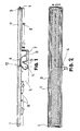
Figure 1 shows a half cross-section of the inventive chute, in elevation view. -
Figure 2 shows a plan view of the inventive chute. -
Figure 3 shows an exploded perspective view of the inventive chute as a whole. -
Figure 4 shows a detail in cross-section of the three-body catch basin. - In the above figures, the numerical references correspond to the following parts and elements:
- 1. Inlet gutter.
- 2. Catch basin.
- 3. Partitions.
- 4. Horizontal outlet.
- 5. Drain trap cover.
- 6. Skirting.
- 7. Tabs.
- 8. Lugs.
- 9. Frame.
- 10. Flange.
- 11. Grille.
- 12. Aeration valve.
- As can be seen in
figures 1 to 4 , the reduced height drainage chute of the invention is designed on the basis of an inlet gutter (1) which presents a catch basin (2) in its bottom in the central position, divided into three bodies by means of two partitions (3), with the central body presenting a horizontal outlet (4). A drain trap cover (5) fits into the catch basin (2), and presents two skirtings (6) which are introduced intro the lateral bodies without reaching the bottom thereof and which are kept separated thanks to individual tabs (7). An array of lugs (8) facilitates the introduction of the screws which secure the usual waterproofing fabric, not represented here. - Arranged on the inlet gutter (1) is a frame (9) provided with a flange (10), on which rests a grille (11) with a cross-section in "U".
- Optionally, a conventional aeration valve (12) is provided on the drain trap cover (5).
- The functioning of the inventive chute is as follows. Water collected on the pavement is introduced into the inlet gutter (1) being directed towards the centre from each of its ends, and becoming introduced into the lateral bodies of the catch basin (2) guided by the skirtings (6), in order to overflow on the partitions (3) and be evacuated via the horizontal outlet (4). Once the flow of water has been halted, its level in the drain trap will be that of the partitions (3), ensuring a perfect sealing. If the chute incorporates an aeration valve (12), this will open when a certain depression appears in the horizontal outlet (4), preventing suction of the water stored in the drain trap and preventing the disappearance of the sealing.
- There are a series of variants that will be evident to an expert on the subject which, adapting the embodiment of the design and the means of production, respect the essence of the invention. So, advantageously, the inlet gutter (1) and the drain trap cover (5) will be made by plastic injection and the frame (9) in stainless steel, though other materials with suitable behaviour would also be feasible. The conventional aeration valve (12) can be produced with a lamina structure, spring-loaded ball or any other arrangement that will be thoroughly familiar to the expert on the subject.
Claims (2)
- Reduced height drainage chute with built-in drain trap, of the kind that comprises an inlet gutter (1) provided with a catch basin (2), characterised in that the latter is divided into three bodies by means of two partitions (3), in order to configure a central body provided with a horizontal outlet (4) and two lateral bodies in which are partially introduced the corresponding skirtings (6) of a drain trap cover (5) arranged flush with the bottom of the inlet gutter (1).
- Drainage chute according to claim 1, characterised in that a conventional aeration valve (12) is arranged on the drain trap cover (5).
Applications Claiming Priority (1)
| Application Number | Priority Date | Filing Date | Title |
|---|---|---|---|
| ES201130155U ES1074756Y (en) | 2011-02-15 | 2011-02-15 | REDUCED HEIGHT DRAINAGE CHANNEL WITH INTEGRATED SIFON |
Related Parent Applications (1)
| Application Number | Title | Priority Date | Filing Date |
|---|---|---|---|
| ES201130155U Previously-Filed-Application | 2011-02-15 |
Publications (2)
| Publication Number | Publication Date |
|---|---|
| EP2532795A2 true EP2532795A2 (en) | 2012-12-12 |
| EP2532795A3 EP2532795A3 (en) | 2015-10-21 |
Family
ID=44063607
Family Applications (1)
| Application Number | Title | Priority Date | Filing Date |
|---|---|---|---|
| EP12000971.7A Withdrawn EP2532795A3 (en) | 2011-02-15 | 2012-02-15 | Reduced height drainage chute with built-in drain trap |
Country Status (3)
| Country | Link |
|---|---|
| EP (1) | EP2532795A3 (en) |
| ES (1) | ES1074756Y (en) |
| RU (1) | RU2012105142A (en) |
Cited By (4)
| Publication number | Priority date | Publication date | Assignee | Title |
|---|---|---|---|---|
| EP2808458A1 (en) | 2013-05-29 | 2014-12-03 | WEDI GmbH | Water drainage device for a shower and shower floor element |
| CN106400938A (en) * | 2016-12-08 | 2017-02-15 | 中国电子系统工程第四建设有限公司 | Lateral drainage type floor drain |
| EP3567169A1 (en) * | 2018-05-11 | 2019-11-13 | Viega Technology GmbH & Co. KG | Drainage fitting |
| BE1032022B1 (en) * | 2023-10-02 | 2025-04-28 | Carrodrain | Drain assembly, drain body for use in such assembly and odour trap for use in such assembly |
Families Citing this family (1)
| Publication number | Priority date | Publication date | Assignee | Title |
|---|---|---|---|---|
| ES2555671B1 (en) * | 2014-07-04 | 2016-09-20 | Baroan Rioja, S.L. | Drain device with non-circular inlet hole |
Citations (1)
| Publication number | Priority date | Publication date | Assignee | Title |
|---|---|---|---|---|
| EP1854929A1 (en) | 2006-05-11 | 2007-11-14 | Easy Sanitairy Solutions B.V. | Drain |
Family Cites Families (6)
| Publication number | Priority date | Publication date | Assignee | Title |
|---|---|---|---|---|
| BE858266A (en) * | 1977-08-31 | 1977-12-16 | Ericson Sture | WASTE WATER DISCHARGE SYSTEM WITH SIPHON |
| JPS6015826Y2 (en) * | 1981-05-25 | 1985-05-17 | 株式会社伸晃 | drain trap |
| ES1043234Y (en) * | 1999-06-11 | 2000-05-01 | Jimten Sa | AERATION VALVE ADAPTED TO AN EVACUATION NETWORK. |
| NL1025765C2 (en) * | 2004-03-18 | 2004-09-06 | Jered Nijhof | Drain in bathroom or shower cabin has odor excluder, channel part, base wall and upstanding long side walls |
| ITVR20040045A1 (en) * | 2004-04-02 | 2004-07-02 | Dakota Metal Plastic Works Llc | INSPECTION COCKPIT WITH SIPHON FOR THE COLLECTION AND FLOW OF LIQUIDS. |
| FR2928156B1 (en) * | 2008-02-29 | 2014-05-23 | Farhooman Davoudi | BONDE ASSEMBLY / SIPHON OF EVACUATION CONSISTS OF SEVERAL GUARDS OF WATER |
-
2011
- 2011-02-15 ES ES201130155U patent/ES1074756Y/en not_active Expired - Fee Related
-
2012
- 2012-02-15 EP EP12000971.7A patent/EP2532795A3/en not_active Withdrawn
- 2012-02-15 RU RU2012105142/03A patent/RU2012105142A/en not_active Application Discontinuation
Patent Citations (1)
| Publication number | Priority date | Publication date | Assignee | Title |
|---|---|---|---|---|
| EP1854929A1 (en) | 2006-05-11 | 2007-11-14 | Easy Sanitairy Solutions B.V. | Drain |
Cited By (5)
| Publication number | Priority date | Publication date | Assignee | Title |
|---|---|---|---|---|
| EP2808458A1 (en) | 2013-05-29 | 2014-12-03 | WEDI GmbH | Water drainage device for a shower and shower floor element |
| DE102013105542A1 (en) | 2013-05-29 | 2014-12-04 | Wedi Gmbh | Water drainage device for a shower and shower floor element |
| CN106400938A (en) * | 2016-12-08 | 2017-02-15 | 中国电子系统工程第四建设有限公司 | Lateral drainage type floor drain |
| EP3567169A1 (en) * | 2018-05-11 | 2019-11-13 | Viega Technology GmbH & Co. KG | Drainage fitting |
| BE1032022B1 (en) * | 2023-10-02 | 2025-04-28 | Carrodrain | Drain assembly, drain body for use in such assembly and odour trap for use in such assembly |
Also Published As
| Publication number | Publication date |
|---|---|
| EP2532795A3 (en) | 2015-10-21 |
| ES1074756U (en) | 2011-06-08 |
| RU2012105142A (en) | 2013-08-20 |
| ES1074756Y (en) | 2011-09-27 |
Similar Documents
| Publication | Publication Date | Title |
|---|---|---|
| US7108783B2 (en) | Drain inlet | |
| EP2759647B1 (en) | Drain | |
| US8720723B2 (en) | Modular rainwater storage tank system | |
| EP2481332A1 (en) | Sanitary assembly, in particular for shower flush with the floor | |
| EP2540923A3 (en) | Waste-water drain with odour trap | |
| CA2995031C (en) | Floor sink strainer and assembly | |
| EP2532795A3 (en) | Reduced height drainage chute with built-in drain trap | |
| KR200444012Y1 (en) | Drain trap | |
| EP2808458A1 (en) | Water drainage device for a shower and shower floor element | |
| DE202012103906U1 (en) | Shower tray arrangement, especially floor-level shower | |
| EP1813731A2 (en) | Kitchen sink, particularly for domestic applications | |
| KR20160003461U (en) | A draining trap | |
| KR102081750B1 (en) | Drain trap for drainage | |
| KR20130015991A (en) | Cylinder type water storage tank having multi-bulkheads | |
| KR20140005618A (en) | Buoyancy drain traps to prevent odors | |
| JP5842416B2 (en) | Planting container | |
| CA2665085A1 (en) | Stair flower boxes | |
| CN202595890U (en) | Mouse-proof and odor-proof water draining device | |
| KR102398648B1 (en) | Device for excluding early rainwater | |
| DE102010008405A1 (en) | Collecting container for collecting e.g. restraining contaminations of water from refrigerator, has rinsing wall arranged at distance to base of container and above outer separating wall of back-washing chamber | |
| CN203416665U (en) | Planting box | |
| DE102011118676A1 (en) | Fermenting juice separator, has L-shaped profile ring guided in complementary manner and arranged in central container at edge of plate, where profile ring is enclosed in sealing manner and plate comprises increased height edge | |
| WO2018124981A3 (en) | Clear water storage tank with built-in filter | |
| CN202176016U (en) | Ditch cover | |
| JP2011140849A (en) | Rainwater collector |
Legal Events
| Date | Code | Title | Description |
|---|---|---|---|
| PUAI | Public reference made under article 153(3) epc to a published international application that has entered the european phase |
Free format text: ORIGINAL CODE: 0009012 |
|
| AK | Designated contracting states |
Kind code of ref document: A2 Designated state(s): AL AT BE BG CH CY CZ DE DK EE ES FI FR GB GR HR HU IE IS IT LI LT LU LV MC MK MT NL NO PL PT RO RS SE SI SK SM TR |
|
| AX | Request for extension of the european patent |
Extension state: BA ME |
|
| PUAL | Search report despatched |
Free format text: ORIGINAL CODE: 0009013 |
|
| AK | Designated contracting states |
Kind code of ref document: A3 Designated state(s): AL AT BE BG CH CY CZ DE DK EE ES FI FR GB GR HR HU IE IS IT LI LT LU LV MC MK MT NL NO PL PT RO RS SE SI SK SM TR |
|
| AX | Request for extension of the european patent |
Extension state: BA ME |
|
| RIC1 | Information provided on ipc code assigned before grant |
Ipc: E03C 1/295 20060101ALN20150917BHEP Ipc: E03F 5/04 20060101AFI20150917BHEP |
|
| 17P | Request for examination filed |
Effective date: 20160126 |
|
| RBV | Designated contracting states (corrected) |
Designated state(s): AL AT BE BG CH CY CZ DE DK EE ES FI FR GB GR HR HU IE IS IT LI LT LU LV MC MK MT NL NO PL PT RO RS SE SI SK SM TR |
|
| 17Q | First examination report despatched |
Effective date: 20160809 |
|
| STAA | Information on the status of an ep patent application or granted ep patent |
Free format text: STATUS: THE APPLICATION IS DEEMED TO BE WITHDRAWN |
|
| 18D | Application deemed to be withdrawn |
Effective date: 20170221 |