EP2532786A1 - A green sound-absorbent wall - Google Patents
A green sound-absorbent wall Download PDFInfo
- Publication number
- EP2532786A1 EP2532786A1 EP12169358A EP12169358A EP2532786A1 EP 2532786 A1 EP2532786 A1 EP 2532786A1 EP 12169358 A EP12169358 A EP 12169358A EP 12169358 A EP12169358 A EP 12169358A EP 2532786 A1 EP2532786 A1 EP 2532786A1
- Authority
- EP
- European Patent Office
- Prior art keywords
- sound
- absorbent wall
- wall according
- panel
- tank structure
- Prior art date
- Legal status (The legal status is an assumption and is not a legal conclusion. Google has not performed a legal analysis and makes no representation as to the accuracy of the status listed.)
- Withdrawn
Links
Images


Classifications
-
- E—FIXED CONSTRUCTIONS
- E01—CONSTRUCTION OF ROADS, RAILWAYS, OR BRIDGES
- E01F—ADDITIONAL WORK, SUCH AS EQUIPPING ROADS OR THE CONSTRUCTION OF PLATFORMS, HELICOPTER LANDING STAGES, SIGNS, SNOW FENCES, OR THE LIKE
- E01F8/00—Arrangements for absorbing or reflecting air-transmitted noise from road or railway traffic
- E01F8/02—Arrangements for absorbing or reflecting air-transmitted noise from road or railway traffic specially adapted for sustaining vegetation or for accommodating plants ; Embankment-type or crib-type noise barriers; Retaining walls specially adapted to absorb or reflect noise
- E01F8/021—Arrangements for absorbing or reflecting air-transmitted noise from road or railway traffic specially adapted for sustaining vegetation or for accommodating plants ; Embankment-type or crib-type noise barriers; Retaining walls specially adapted to absorb or reflect noise with integral support structure
- E01F8/025—Gabion-type
-
- E—FIXED CONSTRUCTIONS
- E01—CONSTRUCTION OF ROADS, RAILWAYS, OR BRIDGES
- E01F—ADDITIONAL WORK, SUCH AS EQUIPPING ROADS OR THE CONSTRUCTION OF PLATFORMS, HELICOPTER LANDING STAGES, SIGNS, SNOW FENCES, OR THE LIKE
- E01F8/00—Arrangements for absorbing or reflecting air-transmitted noise from road or railway traffic
- E01F8/02—Arrangements for absorbing or reflecting air-transmitted noise from road or railway traffic specially adapted for sustaining vegetation or for accommodating plants ; Embankment-type or crib-type noise barriers; Retaining walls specially adapted to absorb or reflect noise
- E01F8/021—Arrangements for absorbing or reflecting air-transmitted noise from road or railway traffic specially adapted for sustaining vegetation or for accommodating plants ; Embankment-type or crib-type noise barriers; Retaining walls specially adapted to absorb or reflect noise with integral support structure
Definitions
- the present invention relates to the field of green sound-absorbent walls.
- the invention has been developed with regard to green sound-absorbent walls made up of a plurality of panels, which can be fitted alongside or on top of one another to form sound-absorbent and sound-insulating walls which are also very long and high, for example having the function of a noise protection barrier to be placed beside very busy roads, railways, airports, etc.
- the document US 5.361.537 discloses a noise protection wall with a framework that supports a series of cassettes which contain compost in which plants of varying height are precultivated.
- the cassettes are arranged one on top of the other with their green face facing frontwards to form the facade of the noise protection wall.
- a cement slab supports the cassettes centrally.
- a similar wall, where the cassettes are slotted in uprights which support them, is illustrated in the document DE 38 12 394 .
- the aim of the present invention is to improve the green sound-absorbent walls of known type, making them thinner and therefore less bulky and more economical, without thereby sacrificing their sound-proofing and vegetation-growth performance, and without reducing their ease of installation and their reliability over time.
- the reference 1 indicates in an overall sense a first, single-faced, variant of a sound-absorbent wall according to the present invention, comprising a plurality of uprights 2 anchored to the ground in a known way, for example by means of plates 3 bolted to foundations, or similar methods.
- the uprights 2 support a plurality of green sound-absorbent panels 4.
- two adjacent uprights 2 support a plurality of panels 4 placed one above the other, which, in the example of Figures 1 and 2 , are four in number but which could also be more or less according to the desired height of the sound-absorbent wall.
- the uprights 2 have a preferably H-shaped cross section, for a convenient assembling of the panels 4, as better described below.
- FIG. 2 shows an exploded view of four panels 4 placed one above the other, and the two uprights 2 which support them with a pair of gasket strips 5 placed in between.
- Each panel 4 comprises a rear shell structure 6, preferably rectangular, with a plurality of stiffening ribs 7.
- the ribs 7 comprise eight vertical strips 7a and two horizontal strips 7b.
- the vertical strips 7a project preferably into the rear part of the panel, while the horizontal strips 7b project preferably into the front part of the rear shell 6 which faces a mesh 8 fixed to a frame 9 joined to the rear shell 6 preferably, although in a non-limiting way, by means of rivets.
- the mesh 8 is fixed preferably, but not exclusively, to the frame 9 by glue, and is preferably an electrowelded metal mesh, although the use of different types of meshes is not excluded, for example plastic meshes, woven meshes, etc.
- each panel 4 there is placed a filling formed for example by an artificial substratum formed by a mixture of volcanic dust with controlled granulometry, mixed with amenders and fertilisers, made structurally stable by the application of adhesives of natural and/or synthetic origin.
- a substratum with a fibrous matrix can be used, of the mineral wool type, mixed with amenders and fertilisers.
- the substratum allows the development of root systems of plants bedded inside it and the resulting growth of vegetation, which contributes, together with the substratum, to the sound-absorbing or sound-insulating properties of the wall 1.
- each panel 4 is shaped in such a way as to form a sort of channel 30, to house the bottom part 4b (see Figure 6 ) of a panel 4 above, thus making the panels easily stackable one on top of the other, with a good hold widthways between one upright 2 and the other.
- the sound-absorbent wall 1 can be dual-faced and can comprise a double-fronted panel 14.
- two middle shells 16 are shaped substantially like the rear shell 6 of the wall described above, but form, coupled with each other, a compost containment tank on both sides of the double-fronted panel 14.
- Two opposed frames 19 close the middle shell 16 from both sides, each one holding a mesh 18 that is completely the same as the mesh 8 described previously in relation to the panel 4 with only one green face. The space enclosed between the two opposed frames is conveniently used for the passage of pipes for the irrigation system.
- the sides of the panels 4 (like those of the panels 14 in the dual-faced variant of the green sound-absorbent wall 1) slide in between the wings of the H profile of the uprights 2.
- the panels 4 (or the dual-faced panel variants 14) are shaped in such a way as to present a duct 20 which can be used, if required, to house the pipes of an irrigation system, or lighting cables, etc.
- the shaping of the single-faced panels 4 or the dual-faced panels 14 is particularly compact, and results in obtaining a green sound-absorbent wall 1 that is particularly thin and light, yet able to withstand stresses, for example due to the wind.
- a green sound-absorbent wall according to the present invention is particularly valued for carrying out works of notable length and height, for example for the protection from noise of vast stretches of roads or railways.
- a particular advantageous feature is the realisation of single-faced panels 4 (or where necessary dual-faced panels 14) with a rear shell 6 (or middle shells 16) made of a material or shaped in such a way as to reduce the overheating of the root system of the plants.
- the rear shell 6 (or middle shell 16) can be a closed-bottom structure, as illustrated in the drawings and described above, and in that case it is preferably produced from fibreglass or similar materials.
- the rear shell 6 (or middle shell 16) can also be made of metal, but in that case preferably having present an open structure, for example with a series of holes, to encourage airing of the substratum.
Abstract
Description
- The present invention relates to the field of green sound-absorbent walls.
- In particular, the invention has been developed with regard to green sound-absorbent walls made up of a plurality of panels, which can be fitted alongside or on top of one another to form sound-absorbent and sound-insulating walls which are also very long and high, for example having the function of a noise protection barrier to be placed beside very busy roads, railways, airports, etc.
- Various walls of the abovementioned type are known. The document
US 5.361.537 discloses a noise protection wall with a framework that supports a series of cassettes which contain compost in which plants of varying height are precultivated. The cassettes are arranged one on top of the other with their green face facing frontwards to form the facade of the noise protection wall. A cement slab supports the cassettes centrally. A similar wall, where the cassettes are slotted in uprights which support them, is illustrated in the documentDE 38 12 394 . - The aim of the present invention is to improve the green sound-absorbent walls of known type, making them thinner and therefore less bulky and more economical, without thereby sacrificing their sound-proofing and vegetation-growth performance, and without reducing their ease of installation and their reliability over time.
- The abovementioned objectives are achieved by means of a sound-absorbent wall of the type indicated in the preamble, having characteristics indicated in the claims that follow. Other features and advantages will emerge from the following description of a preferred example embodiment of the invention, with reference to the appended drawings, which are given by way of non-limiting example, in which:
-
Figure 1 is a perspective view of an example of a sound-absorbent wall according to the present invention, -
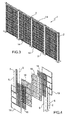
Figure 2 is an exploded view of a portion of the sound-absorbent wall ofFigure 1 , included between two adjacent uprights, and comprising some panels placed one above the other, -
Figure 3 is a perspective view, similar to that ofFigure 1 , of another example of a sound-absorbent wall, dual-faced, according to the present invention, -
Figure 4 is an exploded view, similar to that ofFigure 2 , of a portion of the dual-faced sound-absorbent wall ofFigure 3 , -
Figure 5 is a perspective view in enlarged scale of a detail of the top portion of one of the panels forming the sound-absorbent wall ofFigure 1 , -
Figure 6 is a perspective view in enlarged scale of a detail of the bottom portion of one of the panels forming the sound-absorbent wall ofFigure 1 , -
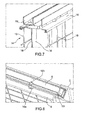
Figure 7 is a perspective view in enlarged scale of a detail of the top portion of one of the dual-faced panels forming the sound-absorbent wall ofFigure 3 , and -
Figure 7 shows, in perspective, a detail of the joint between a panel of the sound-absorbent wall referred to inFigure 1 and a supporting upright. - With reference now to
Figures 1 and 2 , the reference 1 indicates in an overall sense a first, single-faced, variant of a sound-absorbent wall according to the present invention, comprising a plurality ofuprights 2 anchored to the ground in a known way, for example by means ofplates 3 bolted to foundations, or similar methods. Theuprights 2 support a plurality of green sound-absorbent panels 4. In particular, twoadjacent uprights 2 support a plurality ofpanels 4 placed one above the other, which, in the example ofFigures 1 and 2 , are four in number but which could also be more or less according to the desired height of the sound-absorbent wall. Theuprights 2 have a preferably H-shaped cross section, for a convenient assembling of thepanels 4, as better described below. -
Figure 2 shows an exploded view of fourpanels 4 placed one above the other, and the twouprights 2 which support them with a pair ofgasket strips 5 placed in between. Eachpanel 4 comprises arear shell structure 6, preferably rectangular, with a plurality of stiffening ribs 7. In more detail, the ribs 7 comprise eightvertical strips 7a and twohorizontal strips 7b. Thevertical strips 7a project preferably into the rear part of the panel, while thehorizontal strips 7b project preferably into the front part of therear shell 6 which faces amesh 8 fixed to aframe 9 joined to therear shell 6 preferably, although in a non-limiting way, by means of rivets. Themesh 8 is fixed preferably, but not exclusively, to theframe 9 by glue, and is preferably an electrowelded metal mesh, although the use of different types of meshes is not excluded, for example plastic meshes, woven meshes, etc. - Within each
panel 4, there is placed a filling formed for example by an artificial substratum formed by a mixture of volcanic dust with controlled granulometry, mixed with amenders and fertilisers, made structurally stable by the application of adhesives of natural and/or synthetic origin. As an alternative, for example a substratum with a fibrous matrix can be used, of the mineral wool type, mixed with amenders and fertilisers. The substratum allows the development of root systems of plants bedded inside it and the resulting growth of vegetation, which contributes, together with the substratum, to the sound-absorbing or sound-insulating properties of the wall 1. - As better visible in
Figure 5 , thetop portion 4a of eachpanel 4 is shaped in such a way as to form a sort ofchannel 30, to house the bottom part 4b (seeFigure 6 ) of apanel 4 above, thus making the panels easily stackable one on top of the other, with a good hold widthways between one upright 2 and the other. - There are present between the
rear shell 6 and thefront frame 9 someribs Figure 8 ) which also have the function of forming a connecting hole to make water flow between onepanel 4 and thepanel 4 beneath. - As can be seen in
Figures 3 and 4 , and in the detail ofFigure 7 , in one variant, the sound-absorbent wall 1 can be dual-faced and can comprise a double-frontedpanel 14. In this case, twomiddle shells 16 are shaped substantially like therear shell 6 of the wall described above, but form, coupled with each other, a compost containment tank on both sides of the double-frontedpanel 14. Twoopposed frames 19 close themiddle shell 16 from both sides, each one holding amesh 18 that is completely the same as themesh 8 described previously in relation to thepanel 4 with only one green face. The space enclosed between the two opposed frames is conveniently used for the passage of pipes for the irrigation system. - As better visible in
Figure 8 , the sides of the panels 4 (like those of thepanels 14 in the dual-faced variant of the green sound-absorbent wall 1) slide in between the wings of the H profile of theuprights 2. On the side, the panels 4 (or the dual-faced panel variants 14) are shaped in such a way as to present aduct 20 which can be used, if required, to house the pipes of an irrigation system, or lighting cables, etc. - The shaping of the single-
faced panels 4 or the dual-faced panels 14 is particularly compact, and results in obtaining a green sound-absorbent wall 1 that is particularly thin and light, yet able to withstand stresses, for example due to the wind. A green sound-absorbent wall according to the present invention is particularly valued for carrying out works of notable length and height, for example for the protection from noise of vast stretches of roads or railways. - A particular advantageous feature is the realisation of single-faced panels 4 (or where necessary dual-faced panels 14) with a rear shell 6 (or middle shells 16) made of a material or shaped in such a way as to reduce the overheating of the root system of the plants. In more detail, the rear shell 6 (or middle shell 16) can be a closed-bottom structure, as illustrated in the drawings and described above, and in that case it is preferably produced from fibreglass or similar materials. The rear shell 6 (or middle shell 16) can also be made of metal, but in that case preferably having present an open structure, for example with a series of holes, to encourage airing of the substratum.
- Naturally, the principle of the invention remaining the same, the forms of embodiment and details of construction may be varied widely with respect to those described and illustrated, without thereby departing from the scope of the invention.
Claims (10)
- A green sound-absorbent wall, comprising a plurality of panels (4, 14) supported by uprights (2), in which each panel comprises at least one tank structure (6, 16) closed on the front side by a mesh (8, 18), the periphery of which is joined to a frame (9, 19) fixed to the tank structure (6, 16), the tank structure (6, 16) being filled with a substratum for allowing the development of root systems of plants bedded inside it.
- A sound-absorbent wall according to Claim 1, in which the mesh (8, 18) is fixed to the frame (9, 19) by glue.
- A sound-absorbent wall according to any one of the preceding claims, in which the frame (9, 19) is joined to the tank structure (6, 16) by means of rivets or similar.
- A sound-absorbent wall according to any one of the preceding claims, in which the uprights (2) have an H-shaped cross-section and the lateral edge of each panel (4, 14) is inserted between the wings of the H profile of each upright (2).
- A sound-absorbent wall according to any one of the preceding claims, in which each panel (4, 14) has a channel-shaped top edge (4a) for housing the bottom edge (4b) of a panel (4) above.
- A sound-absorbent wall according to any one of the preceding claims, in which the tank structure (6, 16) and the frame (9, 19) are provided with ribs (10a, 10b) spaced apart, which also have the function of forming a connecting hole to make water flow between one panel (4, 14) and a panel beneath.
- A sound-absorbent wall according to any one of the preceding claims, in which the sides of the panels (4, 14) are shaped in such a way as to present a service duct (20).
- A sound-absorbent wall according to any one of the preceding claims, in which the tank structure (6, 16) is made of fibreglass.
- A sound-absorbent wall according to any one of the preceding claims, in which the tank structure (6, 16) has a plurality of holes and is made of metal.
- A sound-absorbent wall according to any one of the preceding claims, in which one or more panels (14) comprises a pair of tank structures (16) coupled back-to-back, each one closed on the front side by a mesh (18) to produce dual-faced panels.
Applications Claiming Priority (1)
| Application Number | Priority Date | Filing Date | Title |
|---|---|---|---|
| IT000325A ITBO20110325A1 (en) | 2011-06-06 | 2011-06-06 | WALL-MOUNTED SOUND-RESISTANT WALL |
Publications (1)
| Publication Number | Publication Date |
|---|---|
| EP2532786A1 true EP2532786A1 (en) | 2012-12-12 |
Family
ID=44584282
Family Applications (1)
| Application Number | Title | Priority Date | Filing Date |
|---|---|---|---|
| EP12169358A Withdrawn EP2532786A1 (en) | 2011-06-06 | 2012-05-24 | A green sound-absorbent wall |
Country Status (2)
| Country | Link |
|---|---|
| EP (1) | EP2532786A1 (en) |
| IT (1) | ITBO20110325A1 (en) |
Cited By (2)
| Publication number | Priority date | Publication date | Assignee | Title |
|---|---|---|---|---|
| WO2017167318A1 (en) * | 2016-03-30 | 2017-10-05 | Jan Eisenreich | Railway or tramway track with modular panels of a low noise barrier |
| WO2022164984A1 (en) * | 2021-01-29 | 2022-08-04 | Aeroaggregates Of North America, Llc | Sound wall with ultra-lightweight foamed glass aggregates |
Citations (5)
| Publication number | Priority date | Publication date | Assignee | Title |
|---|---|---|---|---|
| DE3812394A1 (en) | 1988-04-14 | 1989-11-02 | Wolfgang Behrens | NOISE PROTECTION WALL |
| US5361537A (en) | 1992-06-23 | 1994-11-08 | Wolfgang Behrens | Noise protection wall |
| FR2872381A1 (en) * | 2004-06-30 | 2006-01-06 | Canevaflor Soc Par Actions Sim | STRUCTURE FOR VEGETABLE WALL |
| FR2902283A1 (en) * | 2006-06-14 | 2007-12-21 | Claude Caillet | Vegetal wall system for soilless plant cultivation, has tubs, supported in rail, with frontal faces closed by grille, bank sheet fixed on lock rail to mask rail end, and textile fabric interposed between grille and substrate |
| FR2902602A1 (en) * | 2006-06-23 | 2007-12-28 | Etude Et Rech Polytechnic Du V | Soilless cultivation device for cultivating plants, has bench and cover with openings to let roots of plants pass through openings for implantation of plants in substrate, where plants projects from bench through openings |
-
2011
- 2011-06-06 IT IT000325A patent/ITBO20110325A1/en unknown
-
2012
- 2012-05-24 EP EP12169358A patent/EP2532786A1/en not_active Withdrawn
Patent Citations (5)
| Publication number | Priority date | Publication date | Assignee | Title |
|---|---|---|---|---|
| DE3812394A1 (en) | 1988-04-14 | 1989-11-02 | Wolfgang Behrens | NOISE PROTECTION WALL |
| US5361537A (en) | 1992-06-23 | 1994-11-08 | Wolfgang Behrens | Noise protection wall |
| FR2872381A1 (en) * | 2004-06-30 | 2006-01-06 | Canevaflor Soc Par Actions Sim | STRUCTURE FOR VEGETABLE WALL |
| FR2902283A1 (en) * | 2006-06-14 | 2007-12-21 | Claude Caillet | Vegetal wall system for soilless plant cultivation, has tubs, supported in rail, with frontal faces closed by grille, bank sheet fixed on lock rail to mask rail end, and textile fabric interposed between grille and substrate |
| FR2902602A1 (en) * | 2006-06-23 | 2007-12-28 | Etude Et Rech Polytechnic Du V | Soilless cultivation device for cultivating plants, has bench and cover with openings to let roots of plants pass through openings for implantation of plants in substrate, where plants projects from bench through openings |
Cited By (2)
| Publication number | Priority date | Publication date | Assignee | Title |
|---|---|---|---|---|
| WO2017167318A1 (en) * | 2016-03-30 | 2017-10-05 | Jan Eisenreich | Railway or tramway track with modular panels of a low noise barrier |
| WO2022164984A1 (en) * | 2021-01-29 | 2022-08-04 | Aeroaggregates Of North America, Llc | Sound wall with ultra-lightweight foamed glass aggregates |
Also Published As
| Publication number | Publication date |
|---|---|
| ITBO20110325A1 (en) | 2012-12-07 |
Similar Documents
| Publication | Publication Date | Title |
|---|---|---|
| RU2370020C2 (en) | Construction for greening up wall | |
| AU2009101348A4 (en) | Green wall system | |
| US7627983B1 (en) | Modular, wall-mounted plant growing system | |
| US20110146150A1 (en) | Integrated planter box/trellis combination | |
| NL2004060C2 (en) | BUILDING BLOCK AND WALL BUILT FROM A MULTIPLE OF THESE BUILDING BLOCKS. | |
| EP2532786A1 (en) | A green sound-absorbent wall | |
| JP3549130B2 (en) | Planting wall and planting container used for it | |
| WO2008146131A2 (en) | Method and device for creating a turf or a vegetated surface in various spatial positions | |
| US10482864B1 (en) | Portable acoustical blocking system | |
| US8826591B2 (en) | Modular interconnectable units for macro planter structures | |
| JP2015223168A (en) | Wall greening construction method | |
| KR101669255B1 (en) | Eco sound barrior tunnel having creeper roof and construction method of the same | |
| RU156212U1 (en) | NOISE PROTECTION | |
| JP2012117347A (en) | Folded-plate roof supporting structure | |
| NL2007822C2 (en) | SOUND PROTECTION PANEL. | |
| KR101048499B1 (en) | Four season vegetation loess sound proof wall and construction method using the same | |
| CN108343000B (en) | Sound absorption and insulation unit and greening sound barrier using same | |
| US11011148B1 (en) | Portable decorative acoustical blocking system | |
| RU139730U1 (en) | MULTIFUNCTIONAL MODULES FOR EXPANSION OF THE BUILDING AREA | |
| RU199997U1 (en) | Fencing structure with decorative finishing | |
| KR20080028995A (en) | All-weather farming house | |
| NL1036651C2 (en) | GREATABLE FACADE SYSTEM AND MESH. | |
| RU94804U1 (en) | GREENHOUSE | |
| CN101220581A (en) | Tridimensional greening sound-proof wall and method for manufacturing same | |
| JP6876420B2 (en) | Green wall structure |
Legal Events
| Date | Code | Title | Description |
|---|---|---|---|
| PUAI | Public reference made under article 153(3) epc to a published international application that has entered the european phase |
Free format text: ORIGINAL CODE: 0009012 |
|
| AK | Designated contracting states |
Kind code of ref document: A1 Designated state(s): AL AT BE BG CH CY CZ DE DK EE ES FI FR GB GR HR HU IE IS IT LI LT LU LV MC MK MT NL NO PL PT RO RS SE SI SK SM TR |
|
| AX | Request for extension of the european patent |
Extension state: BA ME |
|
| 17P | Request for examination filed |
Effective date: 20130606 |
|
| RBV | Designated contracting states (corrected) |
Designated state(s): AL AT BE BG CH CY CZ DE DK EE ES FI FR GB GR HR HU IE IS IT LI LT LU LV MC MK MT NL NO PL PT RO RS SE SI SK SM TR |
|
| STAA | Information on the status of an ep patent application or granted ep patent |
Free format text: STATUS: THE APPLICATION IS DEEMED TO BE WITHDRAWN |
|
| 18D | Application deemed to be withdrawn |
Effective date: 20151201 |