EP2532729A2 - Procédé de préparation d'un mélange gazeux injectable dans un réseau de gaz et installation à cet effet - Google Patents
Procédé de préparation d'un mélange gazeux injectable dans un réseau de gaz et installation à cet effet Download PDFInfo
- Publication number
- EP2532729A2 EP2532729A2 EP12004368A EP12004368A EP2532729A2 EP 2532729 A2 EP2532729 A2 EP 2532729A2 EP 12004368 A EP12004368 A EP 12004368A EP 12004368 A EP12004368 A EP 12004368A EP 2532729 A2 EP2532729 A2 EP 2532729A2
- Authority
- EP
- European Patent Office
- Prior art keywords
- gas
- gas stream
- carbon dioxide
- less
- regeneration
- Prior art date
- Legal status (The legal status is an assumption and is not a legal conclusion. Google has not performed a legal analysis and makes no representation as to the accuracy of the status listed.)
- Granted
Links
Images
Classifications
-
- C—CHEMISTRY; METALLURGY
- C10—PETROLEUM, GAS OR COKE INDUSTRIES; TECHNICAL GASES CONTAINING CARBON MONOXIDE; FUELS; LUBRICANTS; PEAT
- C10L—FUELS NOT OTHERWISE PROVIDED FOR; NATURAL GAS; SYNTHETIC NATURAL GAS OBTAINED BY PROCESSES NOT COVERED BY SUBCLASSES C10G, C10K; LIQUEFIED PETROLEUM GAS; ADDING MATERIALS TO FUELS OR FIRES TO REDUCE SMOKE OR UNDESIRABLE DEPOSITS OR TO FACILITATE SOOT REMOVAL; FIRELIGHTERS
- C10L3/00—Gaseous fuels; Natural gas; Synthetic natural gas obtained by processes not covered by subclass C10G, C10K; Liquefied petroleum gas
- C10L3/06—Natural gas; Synthetic natural gas obtained by processes not covered by C10G, C10K3/02 or C10K3/04
- C10L3/08—Production of synthetic natural gas
-
- B—PERFORMING OPERATIONS; TRANSPORTING
- B01—PHYSICAL OR CHEMICAL PROCESSES OR APPARATUS IN GENERAL
- B01D—SEPARATION
- B01D53/00—Separation of gases or vapours; Recovering vapours of volatile solvents from gases; Chemical or biological purification of waste gases, e.g. engine exhaust gases, smoke, fumes, flue gases, aerosols
- B01D53/14—Separation of gases or vapours; Recovering vapours of volatile solvents from gases; Chemical or biological purification of waste gases, e.g. engine exhaust gases, smoke, fumes, flue gases, aerosols by absorption
- B01D53/1425—Regeneration of liquid absorbents
-
- B—PERFORMING OPERATIONS; TRANSPORTING
- B01—PHYSICAL OR CHEMICAL PROCESSES OR APPARATUS IN GENERAL
- B01D—SEPARATION
- B01D53/00—Separation of gases or vapours; Recovering vapours of volatile solvents from gases; Chemical or biological purification of waste gases, e.g. engine exhaust gases, smoke, fumes, flue gases, aerosols
- B01D53/14—Separation of gases or vapours; Recovering vapours of volatile solvents from gases; Chemical or biological purification of waste gases, e.g. engine exhaust gases, smoke, fumes, flue gases, aerosols by absorption
- B01D53/1456—Removing acid components
- B01D53/1475—Removing carbon dioxide
-
- Y—GENERAL TAGGING OF NEW TECHNOLOGICAL DEVELOPMENTS; GENERAL TAGGING OF CROSS-SECTIONAL TECHNOLOGIES SPANNING OVER SEVERAL SECTIONS OF THE IPC; TECHNICAL SUBJECTS COVERED BY FORMER USPC CROSS-REFERENCE ART COLLECTIONS [XRACs] AND DIGESTS
- Y02—TECHNOLOGIES OR APPLICATIONS FOR MITIGATION OR ADAPTATION AGAINST CLIMATE CHANGE
- Y02C—CAPTURE, STORAGE, SEQUESTRATION OR DISPOSAL OF GREENHOUSE GASES [GHG]
- Y02C20/00—Capture or disposal of greenhouse gases
- Y02C20/40—Capture or disposal of greenhouse gases of CO2
Definitions
- the invention relates to a method for providing a gas mixture which can be fed into a gas network with a very high methane content, in which the gas mixture is conditioned in accordance with feed conditions to which the gas network is subject, and a plant suitable for the process.
- Such methods and installations are well known and are used wherever "artificial" natural gas is generated and is to be fed into a gas network in accordance with the applicable regulations (the DVGW G260 / 262 standards).
- An example is a biogas plant, in which first, for example, about 60% methane and 40% carbon dioxide (other ingredients neglected here) containing raw biogas is generated, which is then processed by separating a large part of the carbon dioxide contained in a gas treatment to biomethane. The gas quality of the biomethane is then measured, and the conditioning required for feeding into the gas network (drying, calorific value adjustment, pressure adjustment, odorization) accordingly made to feed the biomethane as a replacement gas or as additional gas in the gas network.
- the invention has for its object to provide the feedable gas mixture in exchange gas quality and with a very high methane content for feeding into the gas network in a method of the type mentioned.
- this object is essentially achieved in that at least two gas streams are combined to form the gas mixture prior to its conditioning, of which a first gas stream next to a methane produced by catalytic methanation still at least one component in a relation to the first gas stream first Containing residual portion and a second gas stream has a very high methane content, wherein a related to the gas mixture after the merger second fraction of the residual component is less than the first portion, and / or the relative methane content of the gas mixture after the merger over that of the first gas stream is increased.
- the solution is based on the finding that conditioning a gas mixture produced by combining two gas streams originating from different sources compensates for an undesirable characteristic of the composition of a gas stream for merging with the other gas stream having different properties with respect to this property can be.
- Such a property could relate to the methane content in the individual gas streams and the gas mixture resulting therefrom, but the proportion of a different residual component, in particular the hydrogen content, is also considered to be quite substantial.
- a gas mixture can be generated outside the range specified by the chemical equilibrium of the methanation reaction.
- One of the two gas streams emerges from the catalytic methanation of a reactant gas and, after leaving the methanation reactor, essentially contains carbon dioxide and hydrogen in addition to methane as main components.
- This hydrogen content of the first gas stream before combining should preferably already be 6% or less, preferably 4% or less, in particular 3% or less be.
- a content of 92% or higher, preferably 94% or higher, in particular 96% or higher is considered to be beneficial.
- this already fulfilling the relevant standards first gas flow even beyond the standards required improved gas quality achieved by the merger of the invention.
- a further proportion of a further residual component, in particular carbon dioxide, contained in the production of the first gas stream can expediently be at least partially separated before the merger, so that in the first gas stream only 4% or less, preferably 2% or less, in particular 1% or less remains.
- a particularly high gas quality can be achieved by the decoupled principle on the one hand the "dilution" of a residual component and on the other hand, the "filtering out” of the other residual component.
- the second gas stream prefferably has a methane content prior to the merger of 94% or higher, preferably 96% or higher, more preferably 98% or higher, and especially hydrogen as a residual component in a proportion of 1% or less , preferably 0.5% or less, in particular 0.2% or less is present.
- a separation of carbon dioxide components from the second gas stream is usually required.
- Appropriate technologies are already available in the art with a high achievable degree of carbon dioxide removal, such as laundry, in the CO 2 in washing liquid goes into solution, is pumped to a regeneration unit, where it is released in the regeneration and re-CO 2 Recording is available.
- a gas treatment based on amine scrubbing mention may be made of a gas treatment based on amine scrubbing.
- the quantitative ratio of the first gas stream to the second gas stream in the merger is 1: 5 or greater, preferably 1: 4 or greater, in particular 1: 3 or greater, and / or 6: 5 or less, preferably 1 : 1 or smaller, in particular 2: 3 or smaller.
- the gas produced by the source of the second gas stream is suitable for removing carbon dioxide.
- the separated carbon dioxide is used to form the educt gas whose catalytic methanation forms the source of the first gas stream.
- the catalytic methanation is carried out under overpressure.
- carbon dioxide recovery from the washing liquid used for the separation already under pressure for example in the range of 4 to 7 bar.
- amine scrubbing for the technique used for carbon dioxide removal.
- the regeneration of the amine-containing scrubbing liquid used for the carbon dioxide separation from the first gas stream may take place at the same location as that of the scrubbing liquid for the second gas stream, i. for both gas streams, the same regeneration plant, but separate washing columns can be provided.
- an amine wash can be used, but the invention is not limited to such.
- the invention expediently provides for the regeneration of the washing liquid to use a heat obtained from the exothermic catalytic methanation reaction, in particular via a circulated in a heat transfer fluid, such as a thermal oil.
- a heat transfer fluid such as a thermal oil.
- This aspect of the invention is also disclosed independently of the merging of the gas streams and considered to be independently protectable.
- the invention thus also relates to a process in which a reactant gas is catalytically methanized to a product gas which is dissipated in a first gas stream, in which the heat energy obtained during the exothermic methanation is used for the regeneration of a washing liquid, which for separating a carbon dioxide content of a serves from a different source, in particular a biogas plant originating methane-rich second gas stream, in particular, the liberated in the washing liquid regeneration carbon dioxide forms a component of the educt gas for the catalytic methanation.
- heat can also be used for the wash liquid regeneration, which is obtained from the combustion of a gas fraction branched off from the second gas stream before the CO 2 separation, in particular by means of a combined heat and power plant.
- the origin of the second gas stream is a biogas plant, possibly including already contained desulfurization of the raw biogas or further purification of the raw biogas.
- This source is particularly suitable for a low hydrogen and very high methane content after carbon dioxide removal.
- An already existing biogas plant with downstream gas treatment can also be suitably retrofitted by means of catalytic methanation carried out according to one of the above process aspects, whereby the total amount of gas that can be fed in can be increased and the release of harmful CO 2 can be reduced.
- the quantitative ratio and / or the absolute volume flows of the first and second gas flow of the merge is recorded and stored in particular.
- the respective contribution of the individual gas streams to the jointly formed and fed gas mixture can be recorded and used for a separate accounting and billing. This is also important if the provision of the two gas streams is in one hand, but the different origin of the gas streams leads to a different balance-sheet evaluation with the same amount of gas fed in.
- the object is achieved by a system for providing a feedable into a gas network gas mixture with very high methane content with the further features of claim 18, which has the system components required for carrying out the process and whose control device is designed to carry out the method.
- the invention proposes a plant according to claim 19.
- the system is also designed in particular for the realization of the further method aspects described above and has corresponding devices and / or lines, as listed in claim 20.
- a one-stage or multistage, in particular two-stage, methanization reactor for use in such a plant for carrying out the process according to the invention is also provided, or the use of a methanation reactor for carrying out the process according to the invention under protection, in particular as a structural unit together with an electrolyzer for producing the hydrogen converted in the methanation process.
- the invention also provides a gas mixture with very high methane content and in particular very low hydrogen content under protection, which was prepared by the method according to the invention.
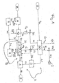
- FIG. 1 The only FIG. 1 The drawing schematically illustrates a multi-component system, based on the method of the invention will be explained in a concrete embodiment.
- the illustrated plant converts a waste R that can be used for biogas production as a raw material into a gas mixture AB with a very high methane content and very low hydrogen content which can be fed into a gas network 2, using a power P EL supplied by a power network 5, without (at least if the electric power P EL to release significant amounts of carbon dioxide.
- the fed into the gas network 2 gas (gas mixture) AB is fed in this embodiment in a flow of 925 standard cubic meters per hour (Nm 3 / h) as natural gas substitute in exchange gas quality in the gas network 2. It has a methane content of more than 98%, and has a hydrogen content and a carbon dioxide content of less than 1% each.
- the gas to be fed AB is conditioned in a feed system 1 to the feed conditions to which the gas network 2 is subject. This includes in per se known manner, if necessary, a drying of the gas, a calorific value to the required calorific value with the addition of, for example, butane or propane, and an increase in pressure of the gas for pressure adjustment to the gas network 2. If necessary, in the feed system 1 thereto by suitable known measuring systems the gas quality / composition and / or other parameters measured to perform the conditioning suitable.
- the gas to be conditioned is formed here from two gas streams originating from different sources, which are combined at the feed system 1.
- the first gas stream A is described, which is fed to the feed system 1 in a gas volume flow of about 330 ⁇ 3 Nm 3 / h in this embodiment.
- Source of the first gas stream A is a 6.3 MW operated in this embodiment conversion plant 30, the essential components of an electrolyzer for the production of hydrogen using the electric power P EL provided by the power network 5 and a example of two-stage running and operating under pressure reactor, in which a reactant gas is catalytically methanized from the electrolytically provided hydrogen and supplied carbon dioxide in a manner known per se.
- the product gas produced at the outlet of the methanation reactor of the conversion plant 30 is supplied to a scrubbing column 3 in a section A1 of the first gas stream A under overpressure, in this embodiment about 5 bar and a gas volume flow of 350 Nm 3 / h in de facto negligible residual constituents of the following composition : 92% CH 4 , 2% H 2 , 6% CO 2 .
- the catalytic methanation is controlled towards low hydrogen contents in the product gas, for example by varying the educt gas composition from the stoichiometric ratio in the form of excess carbon dioxide given for the methanation reaction equations.
- the scrubbing column 3 a large part of the carbon dioxide contained in the first gas stream A in the first section A1 is separated off.
- an amine wash is used as separation technology, and the operation of the wash column 3 is also carried out at overpressure, here about 5 bar. Due to the utilization of the pressure already prevailing in section A1 of the first gas stream A, the scrubbing column 3 can be dimensioned smaller than would be the case, for example, under atmospheric conditions.
- the first gas stream A in this embodiment also has a gas volume flow of about 330 ⁇ 3 Nm 3 / h and a composition of about 97% methane, 2% hydrogen and 1% carbon dioxide ,
- the origin of the second gas stream B in this exemplary embodiment is a biogas plant 10, which here is able to process a waste R usable as biogas as raw material. Before the waste R is fed into the biogas plant 10, however, it is still subjected to a sanitation 6 in which any germs present are killed by heating to about 90 °.
- the biogas plant 10 is operated in such a way that at the outlet thereof a gas volume flow of 1000 Nm 3 / h of a raw biogas which has already been desulphurized in the biogas plant 10 and is purified there or downstream.
- a gas volume flow of 1000 Nm 3 / h of a raw biogas which has already been desulphurized in the biogas plant 10 and is purified there or downstream.
- the methane content and the carbon dioxide content of the raw biogas ie its main components present, except for residual components and impurities contained in very small amounts, will vary. However, this variation is of secondary importance for the rest, since the first section B1 of the second gas stream B, a gas treatment plant 20 is connected downstream, in which anyway the majority of the carbon dioxide contained in the second gas stream B z. B. is separated under atmospheric conditions.
- the amine scrubbing per se is known in the art and will not be described further here. Other washing methods as explained above could also be used.
- the gas treatment plant 20 is designed in this embodiment to a high degree of separation, so that the second gas stream B in the subsequent to the gas treatment section B2 at a gas flow rate of about 600 Nm 3 / h, a methane content of has about 99%, and in addition to the inevitable residual amounts contained in negligible amount only has a carbon dioxide content of about 1%.
- the composition of the gas mixture obtained after combining the first gas stream A and the second gas stream B and to be conditioned in the feed system 1 thus depends not only on the compositions of the individual gas streams but also on their gas volume flows.
- the ratio of the gas volume flows of the first gas flow A to the second gas flow B is approximately 1: 2, whereby the relative hydrogen content of the final mixture AB is reduced compared to the relative hydrogen content in the section A2 of the first gas flow A and is only 1% or less ,
- the methane content of the final mixture AB in comparison to that of the first gas stream A in section A2 is still increased to over 98%.
- the gas volume flows of the first gas stream A in the section A2 and the second gas stream B in the section B2 are suitably regulated in accordance with the hydrogen contained in the first gas stream Conversion plant 30 in relation to the biogas plant 10 dimensioned accordingly.
- a portion of the raw biogas can be diverted in the region of the first section B1 of the second gas stream B, wherein the diverted raw biogas D can be supplied via a line section D1, for example, a cogeneration unit 8 for direct combustion and heat production.
- the heat generated by the cogeneration unit 8 can be used directly for the amine regeneration 24 (lines G2, G12), while the electrical energy generated by the cogeneration unit 8 either used locally or possibly fed into the power grid.
- the branched off raw biogas D could also be additionally or alternatively fired in a gas boiler 7 in order to supply the amount of heat required for the sanitation 6 (lines F2 and F12).
- the gas quantities originating from the individual gas streams A and B are determined directly from suitable measurement data or are derived indirectly, in order accordingly to the Gas network 2 fed gas mixture balance to be assigned to the different sources. This is not necessary in the alternative of separate feed-in, in which the relevant data are collected anyway in the then independent feed-in stations.
- the two gas streams A and B could be carried out without further interaction of the components switched into the gas streams.
- the embodiment still optionally provides individually or in combination feasible couplings, which are described below:
- a gas line C is provided to supply from the amine regeneration 24 of the gas treatment plant 20 of the second gas stream B in the regeneration of the amine-containing scrubbing liquid released carbon dioxide conversion system 30 of the first gas stream A to the required for the catalytic methanation carbon dioxide all or partly to provide.
- the amine regeneration can already be carried out under excess pressure, for example 4 to 7 bar, to provide the carbon dioxide already pre-compressed.
- a carbon dioxide stream of about 400 Nm 3 / h below 4 to 7 bar is provided in the line section C1 adjacent to the amine regeneration, of which about 330-360 Nm 3 / h (CO 2 325 + CO 2 excess) are fed as Eduktgas justify for the catalytic methanation of the conversion plant 30.
- a valve arrangement VC is inserted into the carbon dioxide line C, with which an excess carbon dioxide content C3 can be discharged.
- an implementation of the further aspect of the invention is provided, to use the amine regeneration 24 provided in the gas treatment plant 20 of the second gas stream B also for the required regeneration of the amine scrubbing carried out in the scrubbing column 3 in the first gas stream A.
- oxygen is still produced, in this embodiment in an amount of 625 Nm 3 / h, which could in principle be released to the outside, or could otherwise be removed or filled.
- a portion E2 of the generated oxygen stream E1 is removed in this embodiment by means of a valve arrangement VE and used in an amount of about 3 Nm 3 / h for the performed in the biogas plant 10 desulfurization of the gas generated therein.
- an aerobic decomposition process in the biogas plant 10 can be promoted while avoiding a supply of nitrogen.
- the remaining amount E3 of the generated oxygen of approximately 622 Nm 3 / h in this exemplary embodiment can then be used appropriately as described above.
- a useful heat cycle G is provided in this embodiment, with the help of which a part of the waste heat generated in the conversion plant 30 the amine regeneration 24 in the gas treatment plant 20 is used.
- the conversion plant 30 at a lower temperature level in this embodiment provides 70 ° useful heat F in the scope here up to 2000 kW, which is used for example for the biogas plant 10, but can also contribute to the heating in the sanitation 6 , This is indicated in the figure by the line section F1.
- a recooling 9 of excess heat can be coupled into the useful heat cycle F via a valve arrangement VF and the line F3.
- the conversion system 30 are also operated in intermittent operation, the system 30 runs at full power, if from the power grid 5 excess, from regenerative sources (wind / sun) supplied power in excess and is subtracted, whereby the network is also stabilized while it is switched off or driven at lower power, if the provision of electric power P EL is considered to be unfavorable in total energy consideration ,
Landscapes
- Chemical & Material Sciences (AREA)
- Oil, Petroleum & Natural Gas (AREA)
- Engineering & Computer Science (AREA)
- Chemical Kinetics & Catalysis (AREA)
- General Chemical & Material Sciences (AREA)
- Organic Chemistry (AREA)
- Gas Separation By Absorption (AREA)
Applications Claiming Priority (1)
| Application Number | Priority Date | Filing Date | Title |
|---|---|---|---|
| DE102011103994A DE102011103994A1 (de) | 2011-06-10 | 2011-06-10 | Verfahren zum Bereitstellen eines in ein Gasnetz einspeisbaren Gasgemisches und dafür geeignete Anlage |
Publications (3)
| Publication Number | Publication Date |
|---|---|
| EP2532729A2 true EP2532729A2 (fr) | 2012-12-12 |
| EP2532729A3 EP2532729A3 (fr) | 2013-02-27 |
| EP2532729B1 EP2532729B1 (fr) | 2018-09-05 |
Family
ID=46319539
Family Applications (1)
| Application Number | Title | Priority Date | Filing Date |
|---|---|---|---|
| EP12004368.2A Active EP2532729B1 (fr) | 2011-06-10 | 2012-06-08 | Procédé de préparation d'un mélange gazeux injectable dans un réseau de gaz et installation à cet effet |
Country Status (5)
| Country | Link |
|---|---|
| EP (1) | EP2532729B1 (fr) |
| DE (1) | DE102011103994A1 (fr) |
| ES (1) | ES2688459T3 (fr) |
| PT (1) | PT2532729T (fr) |
| TR (1) | TR201815054T4 (fr) |
Cited By (4)
| Publication number | Priority date | Publication date | Assignee | Title |
|---|---|---|---|---|
| ITRM20130367A1 (it) * | 2013-06-26 | 2014-12-27 | Agenzia Naz Per Le Nuove Tecnologie L Ener | Gruppo per la produzione di metano da gas emesso dal suolo |
| WO2015004143A1 (fr) * | 2013-07-09 | 2015-01-15 | Mitsubishi Hitachi Power Systems Europe Gmbh | Procédé de méthanisation et centrale comprenant la méthanisation de co2 provenant des gaz brûlés de la centrale |
| CN104327895A (zh) * | 2014-11-10 | 2015-02-04 | 北京华福工程有限公司 | 一种氢碳比控制系统及控制方法 |
| EP2965800A1 (fr) * | 2014-07-08 | 2016-01-13 | Airbus DS GmbH | Procédé et dispositif de traitement de gaz |
Families Citing this family (2)
| Publication number | Priority date | Publication date | Assignee | Title |
|---|---|---|---|---|
| DE102012107347A1 (de) * | 2012-08-09 | 2014-02-13 | Evonik Industries Ag | Verfahren zur Erlangung von einem kohlenwasserstoffhaltigen Gas |
| DE102013102969A1 (de) | 2013-03-22 | 2014-09-25 | Sunfire Gmbh | Verfahren zum Herstellen von vorwiegend flüssigen Kohlenwasserstoffen sowie Anordnung |
Family Cites Families (5)
| Publication number | Priority date | Publication date | Assignee | Title |
|---|---|---|---|---|
| GB1391034A (en) * | 1973-02-05 | 1975-04-16 | Metallgesellschaft Ag | Process for the manufacture of a gas interchangeable with natural gas |
| GB2383276B (en) * | 2001-12-21 | 2005-06-08 | Statoil Asa | Acid gas removal |
| DE102008025224A1 (de) * | 2008-05-27 | 2009-12-03 | Linde Ag | Aminwäsche |
| US8007567B2 (en) * | 2008-08-13 | 2011-08-30 | A & B Process Systems Corporation | Apparatus and method for biogas purification |
| DE102009018126B4 (de) * | 2009-04-09 | 2022-02-17 | Zentrum für Sonnenenergie- und Wasserstoff-Forschung Baden-Württemberg | Energieversorgungssystem und Betriebsverfahren |
-
2011
- 2011-06-10 DE DE102011103994A patent/DE102011103994A1/de not_active Withdrawn
-
2012
- 2012-06-08 TR TR2018/15054T patent/TR201815054T4/tr unknown
- 2012-06-08 EP EP12004368.2A patent/EP2532729B1/fr active Active
- 2012-06-08 PT PT12004368T patent/PT2532729T/pt unknown
- 2012-06-08 ES ES12004368.2T patent/ES2688459T3/es active Active
Non-Patent Citations (1)
| Title |
|---|
| None |
Cited By (8)
| Publication number | Priority date | Publication date | Assignee | Title |
|---|---|---|---|---|
| ITRM20130367A1 (it) * | 2013-06-26 | 2014-12-27 | Agenzia Naz Per Le Nuove Tecnologie L Ener | Gruppo per la produzione di metano da gas emesso dal suolo |
| WO2014207703A1 (fr) * | 2013-06-26 | 2014-12-31 | Agenzia Nazionale Per Le Nuove Tecnologie, L'energia E Lo Sviluppo Economico Sostenibile (Enea) | Ensemble pour la production de méthane à partir du gaz de sol émis par des zones de dégazage |
| WO2015004143A1 (fr) * | 2013-07-09 | 2015-01-15 | Mitsubishi Hitachi Power Systems Europe Gmbh | Procédé de méthanisation et centrale comprenant la méthanisation de co2 provenant des gaz brûlés de la centrale |
| US9885257B2 (en) | 2013-07-09 | 2018-02-06 | Mitsubishi Hitachi Power Systems Europe Gmbh | Flexibly operable power plant and method for the operation thereof |
| US10227901B2 (en) | 2013-07-09 | 2019-03-12 | Mitsubishi Hitachi Power Systems Europe Gmbh | Methanation method and power plant comprising CO2 methanation of power plant flue gas |
| EP2965800A1 (fr) * | 2014-07-08 | 2016-01-13 | Airbus DS GmbH | Procédé et dispositif de traitement de gaz |
| US9919982B2 (en) | 2014-07-08 | 2018-03-20 | Airbus Ds Gmbh | Method and device for gas processing |
| CN104327895A (zh) * | 2014-11-10 | 2015-02-04 | 北京华福工程有限公司 | 一种氢碳比控制系统及控制方法 |
Also Published As
| Publication number | Publication date |
|---|---|
| DE102011103994A1 (de) | 2012-12-13 |
| EP2532729B1 (fr) | 2018-09-05 |
| ES2688459T3 (es) | 2018-11-02 |
| EP2532729A3 (fr) | 2013-02-27 |
| PT2532729T (pt) | 2018-12-14 |
| TR201815054T4 (tr) | 2018-11-21 |
Similar Documents
| Publication | Publication Date | Title |
|---|---|---|
| EP2532729B1 (fr) | Procédé de préparation d'un mélange gazeux injectable dans un réseau de gaz et installation à cet effet | |
| EP1836125B1 (fr) | Procede de production d'hydrogene et d'energie a partir d'un gaz de synthese | |
| EP2562237B1 (fr) | Procédé de préparation d'un gaz à très forte teneur en méthane et installation conçue dans ce but | |
| EP2720788B1 (fr) | Procédé de modification d'un flux gazeux contenant du méthane | |
| DE102019214812A1 (de) | Verfahren und Anlage zur Erzeugung von Synthesegas | |
| EP3739714A1 (fr) | Procédé de fonctionnement d'une installation industrielle et installation industrielle correspondante | |
| EP2682450B1 (fr) | Procédé de méthanisation catalytique et installation de méthanisation | |
| DE102016107457A1 (de) | Methanolsynthese aus Synthesegasen mit Wasserstoffmangel | |
| WO2016115582A1 (fr) | Procédé et système de traitement de gaz de combustion | |
| DE102010017027B3 (de) | Verfahren zum Betrieb von Anlagen zur Erzeugung von anthropogenen und/oder biogenen, methanhaltigen Gasen am Erdgasnetz | |
| EP2595942B2 (fr) | Procédé destiné à préparer un produit gazeux riche en méthane et système approprié | |
| DE3118178A1 (de) | Verfahren zur erhoehung des heizwertes von wasserstoffhaltigen brenngas-gemischen | |
| DE112020001970T5 (de) | Synthetik-Produkt-Herstellungssystem und Synthetik-Produktherstellungsverfahren | |
| DE69925659T2 (de) | Apparat zur Kohlenstoffherstellung unter Verwendung von Biomasse | |
| DE102016002728A1 (de) | Verfahren zur Erzeugung von Synthesegas | |
| DE102012025722B3 (de) | Verfahren zur Verbrennung von Erdgas/Methan | |
| WO2019072762A1 (fr) | Procédé de production combinée de méthanol et d'ammoniac | |
| WO2014060168A2 (fr) | Dispositif de compression de gaz naturel et procédé de production de méthane | |
| DE102006019699A1 (de) | Dampferzeugung in Dampfreformierungsprozessen | |
| DE102021210549A1 (de) | Verfahren zur Ammoniaksynthese und Anlage zur Herstellung von Ammoniak | |
| DE102015216037A1 (de) | Verfahren zur Bereitstellung eines Synthesegases | |
| DE102011002261B4 (de) | Verfahren zum Betrieb von Anlagen zur Erzeugung von anthropogenen und/oder biogenen, methanhaltigen Gasen am Erdgasnetz | |
| DE102019007672A1 (de) | Verfahren und Anlage zur Herstellung von Monoethylenglycol | |
| DE102013211685B4 (de) | Kombiniertes Verfahren zur Nutzung von Roh-Biogas enthaltend Kohlendioxid und ein Nutzgas | |
| DE10238041A1 (de) | Wasserstofferzeuger |
Legal Events
| Date | Code | Title | Description |
|---|---|---|---|
| PUAI | Public reference made under article 153(3) epc to a published international application that has entered the european phase |
Free format text: ORIGINAL CODE: 0009012 |
|
| AK | Designated contracting states |
Kind code of ref document: A2 Designated state(s): AL AT BE BG CH CY CZ DE DK EE ES FI FR GB GR HR HU IE IS IT LI LT LU LV MC MK MT NL NO PL PT RO RS SE SI SK SM TR |
|
| AX | Request for extension of the european patent |
Extension state: BA ME |
|
| PUAL | Search report despatched |
Free format text: ORIGINAL CODE: 0009013 |
|
| AK | Designated contracting states |
Kind code of ref document: A3 Designated state(s): AL AT BE BG CH CY CZ DE DK EE ES FI FR GB GR HR HU IE IS IT LI LT LU LV MC MK MT NL NO PL PT RO RS SE SI SK SM TR |
|
| AX | Request for extension of the european patent |
Extension state: BA ME |
|
| RIC1 | Information provided on ipc code assigned before grant |
Ipc: C10L 3/06 20060101AFI20130118BHEP Ipc: C10L 3/08 20060101ALI20130118BHEP Ipc: B01D 53/14 20060101ALI20130118BHEP |
|
| RAP1 | Party data changed (applicant data changed or rights of an application transferred) |
Owner name: ETOGAS GMBH |
|
| 17P | Request for examination filed |
Effective date: 20130826 |
|
| RBV | Designated contracting states (corrected) |
Designated state(s): AL AT BE BG CH CY CZ DE DK EE ES FI FR GB GR HR HU IE IS IT LI LT LU LV MC MK MT NL NO PL PT RO RS SE SI SK SM TR |
|
| 17Q | First examination report despatched |
Effective date: 20151126 |
|
| RAP1 | Party data changed (applicant data changed or rights of an application transferred) |
Owner name: HITACHI ZOSEN INOVA ETOGAS GMBH |
|
| GRAP | Despatch of communication of intention to grant a patent |
Free format text: ORIGINAL CODE: EPIDOSNIGR1 |
|
| STAA | Information on the status of an ep patent application or granted ep patent |
Free format text: STATUS: GRANT OF PATENT IS INTENDED |
|
| INTG | Intention to grant announced |
Effective date: 20180411 |
|
| GRAS | Grant fee paid |
Free format text: ORIGINAL CODE: EPIDOSNIGR3 |
|
| GRAA | (expected) grant |
Free format text: ORIGINAL CODE: 0009210 |
|
| STAA | Information on the status of an ep patent application or granted ep patent |
Free format text: STATUS: THE PATENT HAS BEEN GRANTED |
|
| AK | Designated contracting states |
Kind code of ref document: B1 Designated state(s): AL AT BE BG CH CY CZ DE DK EE ES FI FR GB GR HR HU IE IS IT LI LT LU LV MC MK MT NL NO PL PT RO RS SE SI SK SM TR |
|
| REG | Reference to a national code |
Ref country code: GB Ref legal event code: FG4D Free format text: NOT ENGLISH |
|
| REG | Reference to a national code |
Ref country code: CH Ref legal event code: EP |
|
| REG | Reference to a national code |
Ref country code: AT Ref legal event code: REF Ref document number: 1037797 Country of ref document: AT Kind code of ref document: T Effective date: 20180915 |
|
| REG | Reference to a national code |
Ref country code: CH Ref legal event code: NV Representative=s name: WERNER FENNER PATENTANWALT, CH |
|
| REG | Reference to a national code |
Ref country code: IE Ref legal event code: FG4D Free format text: LANGUAGE OF EP DOCUMENT: GERMAN |
|
| REG | Reference to a national code |
Ref country code: DE Ref legal event code: R096 Ref document number: 502012013354 Country of ref document: DE |
|
| REG | Reference to a national code |
Ref country code: NO Ref legal event code: T2 Effective date: 20180905 |
|
| REG | Reference to a national code |
Ref country code: ES Ref legal event code: FG2A Ref document number: 2688459 Country of ref document: ES Kind code of ref document: T3 Effective date: 20181102 |
|
| REG | Reference to a national code |
Ref country code: NL Ref legal event code: FP |
|
| REG | Reference to a national code |
Ref country code: PT Ref legal event code: SC4A Ref document number: 2532729 Country of ref document: PT Date of ref document: 20181214 Kind code of ref document: T Free format text: AVAILABILITY OF NATIONAL TRANSLATION Effective date: 20181205 |
|
| REG | Reference to a national code |
Ref country code: SE Ref legal event code: TRGR |
|
| REG | Reference to a national code |
Ref country code: LT Ref legal event code: MG4D |
|
| PG25 | Lapsed in a contracting state [announced via postgrant information from national office to epo] |
Ref country code: FI Free format text: LAPSE BECAUSE OF FAILURE TO SUBMIT A TRANSLATION OF THE DESCRIPTION OR TO PAY THE FEE WITHIN THE PRESCRIBED TIME-LIMIT Effective date: 20180905 Ref country code: GR Free format text: LAPSE BECAUSE OF FAILURE TO SUBMIT A TRANSLATION OF THE DESCRIPTION OR TO PAY THE FEE WITHIN THE PRESCRIBED TIME-LIMIT Effective date: 20181206 Ref country code: LT Free format text: LAPSE BECAUSE OF FAILURE TO SUBMIT A TRANSLATION OF THE DESCRIPTION OR TO PAY THE FEE WITHIN THE PRESCRIBED TIME-LIMIT Effective date: 20180905 Ref country code: RS Free format text: LAPSE BECAUSE OF FAILURE TO SUBMIT A TRANSLATION OF THE DESCRIPTION OR TO PAY THE FEE WITHIN THE PRESCRIBED TIME-LIMIT Effective date: 20180905 Ref country code: BG Free format text: LAPSE BECAUSE OF FAILURE TO SUBMIT A TRANSLATION OF THE DESCRIPTION OR TO PAY THE FEE WITHIN THE PRESCRIBED TIME-LIMIT Effective date: 20181205 |
|
| PG25 | Lapsed in a contracting state [announced via postgrant information from national office to epo] |
Ref country code: HR Free format text: LAPSE BECAUSE OF FAILURE TO SUBMIT A TRANSLATION OF THE DESCRIPTION OR TO PAY THE FEE WITHIN THE PRESCRIBED TIME-LIMIT Effective date: 20180905 Ref country code: AL Free format text: LAPSE BECAUSE OF FAILURE TO SUBMIT A TRANSLATION OF THE DESCRIPTION OR TO PAY THE FEE WITHIN THE PRESCRIBED TIME-LIMIT Effective date: 20180905 Ref country code: LV Free format text: LAPSE BECAUSE OF FAILURE TO SUBMIT A TRANSLATION OF THE DESCRIPTION OR TO PAY THE FEE WITHIN THE PRESCRIBED TIME-LIMIT Effective date: 20180905 |
|
| PG25 | Lapsed in a contracting state [announced via postgrant information from national office to epo] |
Ref country code: RO Free format text: LAPSE BECAUSE OF FAILURE TO SUBMIT A TRANSLATION OF THE DESCRIPTION OR TO PAY THE FEE WITHIN THE PRESCRIBED TIME-LIMIT Effective date: 20180905 Ref country code: CZ Free format text: LAPSE BECAUSE OF FAILURE TO SUBMIT A TRANSLATION OF THE DESCRIPTION OR TO PAY THE FEE WITHIN THE PRESCRIBED TIME-LIMIT Effective date: 20180905 Ref country code: PL Free format text: LAPSE BECAUSE OF FAILURE TO SUBMIT A TRANSLATION OF THE DESCRIPTION OR TO PAY THE FEE WITHIN THE PRESCRIBED TIME-LIMIT Effective date: 20180905 Ref country code: EE Free format text: LAPSE BECAUSE OF FAILURE TO SUBMIT A TRANSLATION OF THE DESCRIPTION OR TO PAY THE FEE WITHIN THE PRESCRIBED TIME-LIMIT Effective date: 20180905 |
|
| PG25 | Lapsed in a contracting state [announced via postgrant information from national office to epo] |
Ref country code: SK Free format text: LAPSE BECAUSE OF FAILURE TO SUBMIT A TRANSLATION OF THE DESCRIPTION OR TO PAY THE FEE WITHIN THE PRESCRIBED TIME-LIMIT Effective date: 20180905 Ref country code: SM Free format text: LAPSE BECAUSE OF FAILURE TO SUBMIT A TRANSLATION OF THE DESCRIPTION OR TO PAY THE FEE WITHIN THE PRESCRIBED TIME-LIMIT Effective date: 20180905 |
|
| REG | Reference to a national code |
Ref country code: DE Ref legal event code: R097 Ref document number: 502012013354 Country of ref document: DE |
|
| PLBE | No opposition filed within time limit |
Free format text: ORIGINAL CODE: 0009261 |
|
| STAA | Information on the status of an ep patent application or granted ep patent |
Free format text: STATUS: NO OPPOSITION FILED WITHIN TIME LIMIT |
|
| PG25 | Lapsed in a contracting state [announced via postgrant information from national office to epo] |
Ref country code: DK Free format text: LAPSE BECAUSE OF FAILURE TO SUBMIT A TRANSLATION OF THE DESCRIPTION OR TO PAY THE FEE WITHIN THE PRESCRIBED TIME-LIMIT Effective date: 20180905 |
|
| 26N | No opposition filed |
Effective date: 20190606 |
|
| PG25 | Lapsed in a contracting state [announced via postgrant information from national office to epo] |
Ref country code: SI Free format text: LAPSE BECAUSE OF FAILURE TO SUBMIT A TRANSLATION OF THE DESCRIPTION OR TO PAY THE FEE WITHIN THE PRESCRIBED TIME-LIMIT Effective date: 20180905 |
|
| PG25 | Lapsed in a contracting state [announced via postgrant information from national office to epo] |
Ref country code: MC Free format text: LAPSE BECAUSE OF FAILURE TO SUBMIT A TRANSLATION OF THE DESCRIPTION OR TO PAY THE FEE WITHIN THE PRESCRIBED TIME-LIMIT Effective date: 20180905 |
|
| REG | Reference to a national code |
Ref country code: BE Ref legal event code: MM Effective date: 20190630 |
|
| PG25 | Lapsed in a contracting state [announced via postgrant information from national office to epo] |
Ref country code: LU Free format text: LAPSE BECAUSE OF NON-PAYMENT OF DUE FEES Effective date: 20190608 Ref country code: BE Free format text: LAPSE BECAUSE OF NON-PAYMENT OF DUE FEES Effective date: 20190630 |
|
| REG | Reference to a national code |
Ref country code: AT Ref legal event code: MM01 Ref document number: 1037797 Country of ref document: AT Kind code of ref document: T Effective date: 20190608 |
|
| PG25 | Lapsed in a contracting state [announced via postgrant information from national office to epo] |
Ref country code: AT Free format text: LAPSE BECAUSE OF NON-PAYMENT OF DUE FEES Effective date: 20190608 |
|
| REG | Reference to a national code |
Ref country code: CH Ref legal event code: NV Representative=s name: SERAINA FENNER, CH |
|
| PG25 | Lapsed in a contracting state [announced via postgrant information from national office to epo] |
Ref country code: CY Free format text: LAPSE BECAUSE OF FAILURE TO SUBMIT A TRANSLATION OF THE DESCRIPTION OR TO PAY THE FEE WITHIN THE PRESCRIBED TIME-LIMIT Effective date: 20180905 |
|
| PG25 | Lapsed in a contracting state [announced via postgrant information from national office to epo] |
Ref country code: HU Free format text: LAPSE BECAUSE OF FAILURE TO SUBMIT A TRANSLATION OF THE DESCRIPTION OR TO PAY THE FEE WITHIN THE PRESCRIBED TIME-LIMIT; INVALID AB INITIO Effective date: 20120608 Ref country code: MT Free format text: LAPSE BECAUSE OF FAILURE TO SUBMIT A TRANSLATION OF THE DESCRIPTION OR TO PAY THE FEE WITHIN THE PRESCRIBED TIME-LIMIT Effective date: 20180905 |
|
| PG25 | Lapsed in a contracting state [announced via postgrant information from national office to epo] |
Ref country code: MK Free format text: LAPSE BECAUSE OF FAILURE TO SUBMIT A TRANSLATION OF THE DESCRIPTION OR TO PAY THE FEE WITHIN THE PRESCRIBED TIME-LIMIT Effective date: 20180905 |
|
| REG | Reference to a national code |
Ref country code: GB Ref legal event code: 732E Free format text: REGISTERED BETWEEN 20220623 AND 20220629 |
|
| REG | Reference to a national code |
Ref country code: NO Ref legal event code: CHAD Owner name: HITACHI ZOSEN INOVA AG, CH |
|
| REG | Reference to a national code |
Ref country code: NL Ref legal event code: PD Owner name: HITACHI ZOSEN INOVA AG; CH Free format text: DETAILS ASSIGNMENT: CHANGE OF OWNER(S), ASSIGNMENT; FORMER OWNER NAME: HITACHI ZOSEN INOVA ETOGAS GMBH Effective date: 20221010 |
|
| REG | Reference to a national code |
Ref country code: DE Ref legal event code: R081 Ref document number: 502012013354 Country of ref document: DE Owner name: HITACHI ZOSEN INOVA AG, CH Free format text: FORMER OWNER: HITACHI ZOSEN INOVA ETOGAS GMBH, 70565 STUTTGART, DE |
|
| REG | Reference to a national code |
Ref country code: ES Ref legal event code: PC2A Owner name: HITACHI ZOSEN INOVA AG Effective date: 20230428 |
|
| P01 | Opt-out of the competence of the unified patent court (upc) registered |
Effective date: 20230523 |
|
| PGFP | Annual fee paid to national office [announced via postgrant information from national office to epo] |
Ref country code: PT Payment date: 20230602 Year of fee payment: 12 Ref country code: NO Payment date: 20230626 Year of fee payment: 12 Ref country code: NL Payment date: 20230616 Year of fee payment: 12 Ref country code: IE Payment date: 20230621 Year of fee payment: 12 Ref country code: FR Payment date: 20230620 Year of fee payment: 12 Ref country code: DE Payment date: 20230622 Year of fee payment: 12 |
|
| PGFP | Annual fee paid to national office [announced via postgrant information from national office to epo] |
Ref country code: TR Payment date: 20230530 Year of fee payment: 12 Ref country code: SE Payment date: 20230614 Year of fee payment: 12 Ref country code: IS Payment date: 20230615 Year of fee payment: 12 |
|
| PGFP | Annual fee paid to national office [announced via postgrant information from national office to epo] |
Ref country code: IT Payment date: 20230630 Year of fee payment: 12 Ref country code: GB Payment date: 20230620 Year of fee payment: 12 Ref country code: ES Payment date: 20230703 Year of fee payment: 12 Ref country code: CH Payment date: 20230702 Year of fee payment: 12 |