EP2532385B1 - Shielding device for irradiation unit - Google Patents
Shielding device for irradiation unit Download PDFInfo
- Publication number
- EP2532385B1 EP2532385B1 EP20110169380 EP11169380A EP2532385B1 EP 2532385 B1 EP2532385 B1 EP 2532385B1 EP 20110169380 EP20110169380 EP 20110169380 EP 11169380 A EP11169380 A EP 11169380A EP 2532385 B1 EP2532385 B1 EP 2532385B1
- Authority
- EP
- European Patent Office
- Prior art keywords
- longitudinal
- shielding element
- irradiation unit
- thickness
- block
- Prior art date
- Legal status (The legal status is an assumption and is not a legal conclusion. Google has not performed a legal analysis and makes no representation as to the accuracy of the status listed.)
- Not-in-force
Links
Images


Classifications
-
- G—PHYSICS
- G21—NUCLEAR PHYSICS; NUCLEAR ENGINEERING
- G21K—TECHNIQUES FOR HANDLING PARTICLES OR IONISING RADIATION NOT OTHERWISE PROVIDED FOR; IRRADIATION DEVICES; GAMMA RAY OR X-RAY MICROSCOPES
- G21K1/00—Arrangements for handling particles or ionising radiation, e.g. focusing or moderating
- G21K1/10—Scattering devices; Absorbing devices; Ionising radiation filters
-
- A—HUMAN NECESSITIES
- A61—MEDICAL OR VETERINARY SCIENCE; HYGIENE
- A61N—ELECTROTHERAPY; MAGNETOTHERAPY; RADIATION THERAPY; ULTRASOUND THERAPY
- A61N5/00—Radiation therapy
- A61N5/10—X-ray therapy; Gamma-ray therapy; Particle-irradiation therapy
- A61N5/1042—X-ray therapy; Gamma-ray therapy; Particle-irradiation therapy with spatial modulation of the radiation beam within the treatment head
-
- A—HUMAN NECESSITIES
- A61—MEDICAL OR VETERINARY SCIENCE; HYGIENE
- A61N—ELECTROTHERAPY; MAGNETOTHERAPY; RADIATION THERAPY; ULTRASOUND THERAPY
- A61N5/00—Radiation therapy
- A61N5/10—X-ray therapy; Gamma-ray therapy; Particle-irradiation therapy
- A61N5/1077—Beam delivery systems
-
- G—PHYSICS
- G21—NUCLEAR PHYSICS; NUCLEAR ENGINEERING
- G21K—TECHNIQUES FOR HANDLING PARTICLES OR IONISING RADIATION NOT OTHERWISE PROVIDED FOR; IRRADIATION DEVICES; GAMMA RAY OR X-RAY MICROSCOPES
- G21K1/00—Arrangements for handling particles or ionising radiation, e.g. focusing or moderating
- G21K1/02—Arrangements for handling particles or ionising radiation, e.g. focusing or moderating using diaphragms, collimators
-
- A—HUMAN NECESSITIES
- A61—MEDICAL OR VETERINARY SCIENCE; HYGIENE
- A61N—ELECTROTHERAPY; MAGNETOTHERAPY; RADIATION THERAPY; ULTRASOUND THERAPY
- A61N5/00—Radiation therapy
- A61N5/10—X-ray therapy; Gamma-ray therapy; Particle-irradiation therapy
- A61N2005/1085—X-ray therapy; Gamma-ray therapy; Particle-irradiation therapy characterised by the type of particles applied to the patient
- A61N2005/1087—Ions; Protons
-
- A—HUMAN NECESSITIES
- A61—MEDICAL OR VETERINARY SCIENCE; HYGIENE
- A61N—ELECTROTHERAPY; MAGNETOTHERAPY; RADIATION THERAPY; ULTRASOUND THERAPY
- A61N5/00—Radiation therapy
- A61N5/10—X-ray therapy; Gamma-ray therapy; Particle-irradiation therapy
- A61N2005/1085—X-ray therapy; Gamma-ray therapy; Particle-irradiation therapy characterised by the type of particles applied to the patient
- A61N2005/109—Neutrons
-
- A—HUMAN NECESSITIES
- A61—MEDICAL OR VETERINARY SCIENCE; HYGIENE
- A61N—ELECTROTHERAPY; MAGNETOTHERAPY; RADIATION THERAPY; ULTRASOUND THERAPY
- A61N5/00—Radiation therapy
- A61N5/10—X-ray therapy; Gamma-ray therapy; Particle-irradiation therapy
- A61N2005/1092—Details
- A61N2005/1094—Shielding, protecting against radiation
-
- A—HUMAN NECESSITIES
- A61—MEDICAL OR VETERINARY SCIENCE; HYGIENE
- A61N—ELECTROTHERAPY; MAGNETOTHERAPY; RADIATION THERAPY; ULTRASOUND THERAPY
- A61N5/00—Radiation therapy
- A61N5/10—X-ray therapy; Gamma-ray therapy; Particle-irradiation therapy
- A61N2005/1092—Details
- A61N2005/1095—Elements inserted into the radiation path within the system, e.g. filters or wedges
-
- A—HUMAN NECESSITIES
- A61—MEDICAL OR VETERINARY SCIENCE; HYGIENE
- A61N—ELECTROTHERAPY; MAGNETOTHERAPY; RADIATION THERAPY; ULTRASOUND THERAPY
- A61N5/00—Radiation therapy
- A61N5/10—X-ray therapy; Gamma-ray therapy; Particle-irradiation therapy
- A61N2005/1092—Details
- A61N2005/1096—Elements inserted into the radiation path placed on the patient, e.g. bags, bolus, compensators
-
- Y—GENERAL TAGGING OF NEW TECHNOLOGICAL DEVELOPMENTS; GENERAL TAGGING OF CROSS-SECTIONAL TECHNOLOGIES SPANNING OVER SEVERAL SECTIONS OF THE IPC; TECHNICAL SUBJECTS COVERED BY FORMER USPC CROSS-REFERENCE ART COLLECTIONS [XRACs] AND DIGESTS
- Y10—TECHNICAL SUBJECTS COVERED BY FORMER USPC
- Y10T—TECHNICAL SUBJECTS COVERED BY FORMER US CLASSIFICATION
- Y10T83/00—Cutting
- Y10T83/04—Processes
- Y10T83/0524—Plural cutting steps
Description
La présente invention se rapporte selon un premier aspect à une méthode d'obtention d'un élément de blindage pour minimiser la pénombre d'un faisceau de hadrons en dehors d'une zone cible, ledit faisceau de hadrons étant issu d'une source et balayé sur ladite zone cible. Selon un second aspect, l'invention se rapporte à un élément de blindage réalisé selon la méthode d'obtention revendiquée. Selon un troisième aspect, la présente invention se rapporte à une unité d'irradiation. Selon un quatrième aspect, la présente invention se rapporte à une méthode de balayage d'une zone cible par un faisceau de hadrons.The present invention relates in a first aspect to a method of obtaining a shielding element for minimizing the penumbra of a hadron beam outside a target area, said hadron beam being derived from a source and scanned on said target area. According to a second aspect, the invention relates to a shielding element made according to the claimed method of obtaining. According to a third aspect, the present invention relates to an irradiation unit. According to a fourth aspect, the present invention relates to a method of scanning a target area by a beam of hadrons.
Les récentes techniques de hadron-thérapie pour le traitement des cancers permettent de délivrer avec précision une dose sur un volume cible, par exemple une tumeur, tout en préservant les tissus environnants. Un appareil de hadron-thérapie comprend un accélérateur de particules produisant un faisceau de particules chargées, un moyen de transport du faisceau et une unité d'irradiation. L'unité d'irradiation délivre une distribution de dose sur le volume cible et comprend généralement des moyens de contrôle de la dose délivrée, comme par exemple une chambre d'ionisation, ainsi que des moyens de contrôle du faisceau, comme par exemple un collimateur ou des aimants de balayage en fonction du mode de délivrance du faisceau employé. Deux grands modes de délivrance de faisceaux sont employés en hadron-thérapie : un premier mode de délivrance comprend les techniques dites de diffusion passive du faisceau et un second mode de traitement plus élaboré comprend les techniques dynamiques de balayage du faisceau.The recent hadron-therapy techniques for the treatment of cancers make it possible to accurately deliver a dose to a target volume, for example a tumor, while preserving the surrounding tissues. A hadron therapy apparatus includes a particle accelerator producing a charged particle beam, a beam transport means, and an irradiation unit. The irradiation unit delivers a dose distribution on the target volume and generally comprises means for controlling the delivered dose, such as, for example, an ionization chamber, as well as beam control means, for example a collimator. or scanning magnets depending on the beam delivery mode employed. Two major modes of beam delivery are employed in hadron therapy: a first mode of delivery includes so-called passive beam scattering techniques and a second more elaborate mode of processing includes dynamic beam scanning techniques.
Les méthodes de diffusion passive font appel à un ensemble d'éléments permettant d'ajuster le trajet des particules jusqu'au point de profondeur maximum de la région à irradier et sur la largeur nécessaire. De manière à obtenir une dose qui coïncide au mieux avec le volume cible, il est nécessaire d'utiliser un compensateur et un collimateur fabriqué spécifiquement pour chaque faisceau du patient. Un défaut majeur de cette technique est que des tissus avoisinants localisés en amont et à l'extérieur du volume cible peuvent être également soumis à des doses élevées de faisceaux. De plus, la fabrication du/des compensateur(s) et du/des collimateur(s) spécifiques à la tumeur du patient et à l'angle d'irradiation est compliquée et coûteuse.Passive diffusion methods use a set of elements to adjust the particle path to the point of maximum depth of the region to be irradiated and the width required. In order to obtain a dose which best coincides with the target volume, it is necessary to use a compensator and a collimator manufactured specifically for each beam of the patient. A major flaw of this technique is that neighboring tissues located upstream and outside the target volume may also be subjected to high doses of beams. In addition, the manufacture of the compensator (s) and collimator (s) specific to the tumor of the patient and the irradiation angle is complicated and expensive.
Aussi, une unité d'irradiation d'un appareil de hadron thérapie délivrant un faisceau selon une méthode de diffusion passive comprend un dispositif de fixation de compensateur et collimateur qui lui est propre. Le dispositif de fixation autorise une tranlation le long de l'axe du faisceau afin de placer compensateur et collimateur au plus près de patient. Le collimateur est généralement usiné dans un bloc de laiton aux dimensions adaptées au dispositif de fixation de collimateur, quelle que soit l'ouverture du collimateur. La hauteur du bloc selon la direction du faisceau doit être suffisante pour empêcher le passage du faisceau. Le poids d'un tel collimateur est relativement élevé, ce qui pose des problèmes de manipulation pour le thérapeute. Souvent un tel collimateur est divisé en plusieurs parties suivant sa hauteur pour des facilités de manutention, néanmoins le poids de ces parties de collimateur reste élevé et ces parties requièrent un alignement précis les unes par rapport aux autres. Un collimateur est situé à l'extrémité de l'unité d'irradiation et à une distance proche du patient, et peut avoir un poids total de l'ordre de 30kg, ce qui impose une unité d'irradiation suffisamment robuste ainsi qu'un système de déplacement puissant dans les cas où la gravité doit être vaincue (irradiation verticale).Also, an irradiation unit of a hadron therapy apparatus delivering a beam according to a passive diffusion method comprises a compensator and collimator attachment device of its own. The fixation device allows tranlation along the axis of the beam in order to place compensator and collimator closer to the patient. The collimator is generally machined in a brass block with dimensions adapted to the collimator attachment device, whatever the collimator opening. The height of the block in the direction of the beam must be sufficient to prevent the passage of the beam. The weight of such a collimator is relatively high, which poses handling problems for the therapist. Often such a collimator is divided into several parts along its height for ease of handling, nevertheless the weight of these collimator parts remains high and these parts require precise alignment with each other. A collimator is located at the end of the irradiation unit and at a close distance from the patient, and can have a total weight of the order of 30 kg, which imposes a sufficiently robust irradiation unit and a powerful displacement system in cases where gravity must be overcome (vertical irradiation).
D'autres collimateurs existent comme par exemple les collimateurs multi-lames tels que décrits dans les documents
Dans un second mode de délivrance de faisceau utilisant des techniques dynamique de balayage du faisceau, comme par exemple la technique du « PBS » (pour Pencil Beam Scanning), décrite dans le document
La distribution des particules du fin faisceau à la sortie de l'unité d'irradiation suit une distribution gaussienne. La largeur σ du faisceau de hadrons à la sortie de l'unité d'irradiation augmente lorsque l'énergie diminue du fait que la dispersion du faisceau dans les matériaux traversés (détecteurs, air,...) avant la sortie de l'unité d'irradiation varie avec l'énergie du faisceau. Pour des faisceaux d'énergie élevée, la largeur σ du faisceau ne dépasse généralement pas les 3mm. Par contre lorsque l'on diminue l'énergie du faisceau, la largeur σ du faisceau augmente dans certains cas jusque 12mm. Pour des zones où le volume cible avoisine des organes critiques, il est alors nécessaire de pouvoir minimiser la pénombre du faisceau autour du volume cible.The distribution of the particles of the fine beam at the output of the irradiation unit follows a Gaussian distribution. The width σ of the hadron beam at the exit of the irradiation unit increases when the energy decreases because the dispersion of the beam in the materials crossed (detectors, air, ...) before the exit of the unit Irradiation varies with the energy of the beam. For beams of high energy, the beam width σ generally does not exceed 3mm. By cons when decreasing the energy of the beam, the width σ of the beam increases in some cases up to 12mm. For areas where the target volume is close to critical organs, it is then necessary to be able to minimize the penumbra of the beam around the target volume.
Un dispositif permettant de réduire la pénombre d'un faisceau de protons ou d'ions carbone délivré sur une cible selon une technique de balayage dynamique est décrit dans le document
Un dispositif d'irradiation utilisant un faisceau de protons fixe et un bloc de blindage est divulgué dans le document
Le but de la présente invention est de pouvoir réaliser selon une méthode plus simple et moins onéreuse un élément de blindage apte à minimiser la pénombre d'un faisceau de hadrons et présentant des dimensions et un poids réduits.The object of the present invention is to be able to achieve in a simpler and less expensive method a shielding element adapted to minimize the penumbra of a hadron beam and having reduced dimensions and weight.
Selon un premier aspect, la présente invention se rapporte à une méthode d'obtention d'un élément de blindage 1 selon la revendication 1.According to a first aspect, the present invention relates to a method for obtaining a
Plus préférablement, ladite étape de rognage tient compte de la largeur (σ) du faisceau de hadrons 2 de telle sorte que ladite paroi 19 ait une épaisseur latérale en au moins un endroit 8 inférieure à cinq fois la largeur (σ) du faisceau 2.More preferably, said trimming step takes into account the width (σ) of the
Selon un mode de réalisation de la méthode de la présente invention, la dite étape de rognage est réalisée de telle sorte à ce que ladite surface externe longitudinale 7b soit semblable à ladite surface interne longitudinale 7a.According to an embodiment of the method of the present invention, said trimming step is performed such that said longitudinal
Selon un mode de réalisation de la méthode de la présente invention, la méthode comprend une étape de réalisation d'un moyen de support 16 pour fixer ledit élément de blindage 1 dans ladite unité d'irradiation 14.According to one embodiment of the method of the present invention, the method comprises a step of producing a support means 16 for fixing said
Selon un premier mode de réalisation dudit moyen de support 16, ledit moyen de support est un rebord situé sur ladite surface externe 7b formé lors de ladite étape de rognage.According to a first embodiment of said support means 16, said support means is a flange located on said
Selon un second mode de réalisation dudit moyen de support 16, ledit moyen de support 16 est un socle réalisé en un matériau de basse densité et présentant une ouverture plus grande ou égale à ladite ouverture 11 de forme semblable audit contour 5, 5a et traversant ladite épaisseur longitudinale 6 dudit bloc (13), de manière à laisser passer ledit faisceau 2.According to a second embodiment of said support means 16, said support means 16 is a base made of a low density material and having an opening greater than or equal to said opening 11 of shape similar to said
Selon un second aspect, la présente invention se rapporte à un élément de blindage 1 obtenu selon l'un des modes de réalisation de la méthode selon le premier aspect de la présente invention.According to a second aspect, the present invention relates to a
Selon un troisième aspect, la présente invention se rapporte à une unité d'irradiation 14 apte à balayer un faisceau de hadrons 2 issu d'une source 3 sur une zone cible 4, ladite unité d'irradiation 14 comprenant un élément de blindage 1 selon le second aspect de la présente invention, positionné entre ladite source 3 et ladite zone cible 4, de manière à minimiser la pénombre du faisceau 2 en dehors de ladite zone cible 4.According to a third aspect, the present invention relates to an
La
La
La
La
La
La
La
La
La
Les figures sont données à titre indicatif et ne constituent pas de limitation de la présente invention. L'élément de blindage selon la présente invention ayant préférablement une forme particulière en fonction de la zone cible à traiter. Par ailleurs, les proportions des dessins ne sont pas respectées.The figures are given for information only and do not constitute a limitation of the present invention. The shielding element according to the present invention preferably has a particular shape depending on the target area to be treated. Moreover, the proportions of the drawings are not respected.
Selon un premier aspect, la présente invention se rapporte à une méthode d'obtention d'un élément de blindage 1 pour minimiser la pénombre d'un faisceau de hadrons 2 balayé sur une zone cible 4 en dehors de ladite zone cible 4, ledit faisceau de hadrons ayant une largeur gaussienne σ, ledit faisceau étant issu d'une source 3 et orienté substantiellement selon un axe z.According to a first aspect, the present invention relates to a method for obtaining a
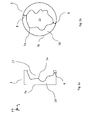
Dans le cas présent, le terme « source » est un point ponctuel à l'origine de la direction prise par le faisceau 2 après avoir été dévié par un premier moyen de balayage 10 selon un axe x et un second moyen de balayage 9 selon un axe y, les deux axes x et y étant orthogonaux entre eux et orthogonaux à un axe z parallèle à la direction du faisceau 2 lorsque celui-ci n'est pas dévié.In the present case, the term "source" is a point point at the origin of the direction taken by the
Selon un mode d'exécution général de la méthode de la présente invention, la méthode d'obtention d'un élément de blindage 1 comprend les étapes de :
- (i) définition d'un contour
fermé 5ou ouvert 5a de laditezone cible 4 ; - (ii) fourniture d'un
bloc 13 ayant une épaisseur longitudinale 6 apte à bloquer le passage du faisceau 2 et ayant unesurface latérale 7c perpendiculaire à ladite épaisseur longitudinale 6; - (iii)formation d'une ouverture, par
exemple un canal 11ou une concavité 17 traversant ladite épaisseur longitudinale 6dudit bloc 13 pour faire passer ledit faisceau, ladite ouverture étant de forme semblable audit contour et formant unesurface interne longitudinale 7a;
Le terme « épaisseur longitudinale » se réfère à une épaisseur selon ledit axe z. Le terme « surface longitudinale » se réfère à une surface parallèle à l'axe z.
- (i) defining a closed or
open contour 5a of saidtarget zone 4; - (ii) providing a
block 13 having alongitudinal thickness 6 capable of blocking the passage of thebeam 2 and having alateral surface 7c perpendicular to saidlongitudinal thickness 6; - (iii) forming an opening, for example a
channel 11 or aconcavity 17 passing through saidlongitudinal thickness 6 of saidblock 13 to pass said beam, said opening being of similar shape to said contour and forming a longitudinalinternal surface 7a;
The term "longitudinal thickness" refers to a thickness along said z axis. The term "longitudinal surface" refers to a surface parallel to the z axis. The
Préférablement, le bloc 13 fourni pour la formation de l'élément de blindage 1 est réalisé en un matériau présentant un pouvoir d'arrêt du faisceau suffisamment élevé et s'activant peu lorsque celui-ci est soumis à l'irradiation. Un matériau généralement utilisé est le laiton car il est un bon compromis satisfaisant à ces deux conditions, est peu couteux et est facile à usiner.Preferably, the
La
La
La méthode d'obtention de l'élément de blindage 1 est caractérisée en ce que ladite étape de rognage (iv) tient compte de la largeur σ du faisceau de hadrons 2 de telle sorte que ladite paroi 19 ait une épaisseur latérale partout supérieure à au moins une fois la largeur σ dudit faisceau. Le terme « épaisseur latérale » se réfère à une épaisseur entre la surface interne longitudinale 7a et la surface externe longitudinale 7b mesurée dans une direction orthogonale audit axe z et perpendiculairement par rapport à la surface interne longitudinale 7a.The method for obtaining the
Pour un appareil de hadron thérapie utilisant une technique de balayage dynamique d'un faisceau sur une zone cible et comprenant un modulateur d'énergie du faisceau, la largeur σ du faisceau varie en fonction de l'énergie du faisceau entre une valeur minimum σmin ( par exemple 3mm) et une valeur maximum σmax (par exemple 12mm). En pratique, l'homme du métier pourra choisir de réaliser ladite étape de rognage (iv) de telle sorte que l'épaisseur latérale de la paroi latérale soit supérieure à trois fois la largeur σ dudit faisceau.For a hadron therapy apparatus using a dynamic beam scanning technique on a target area and including a beam energy modulator, the beam width σ varies as a function of the beam energy between a minimum value σ min (for example 3mm) and a maximum value σ max (for example 12mm). In practice, the skilled person may choose to perform said trimming step (iv) so that the lateral thickness of the side wall is greater than three times the width σ of said beam.
Dans un autre mode d'exécution de la méthode de la présente invention, ladite étape de rognage tient compte de la largeur σ dudit faisceau de telle sorte que ladite paroi 19 ait une épaisseur latérale partout supérieure à au moins une fois la largeur σ dudit faisceau et de telle sorte que ladite paroi 19 ait une épaisseur latérale en au moins un endroit 8 inférieure à cinq fois la largeur σ dudit faisceau.In another embodiment of the method of the present invention, said trimming step takes into account the width σ of said beam such that said
Dans un autre mode d'exécution de la méthode de la présente invention tel que représenté sur la
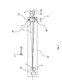
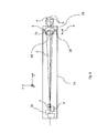
Dans un autre mode d'exécution de la méthode selon l'un quelconque des modes d'exécution précédents, ladite méthode comprend une étape de formation d'un moyen de support 16 pour permettre la fixation de l'élément de blindage 1 dans une unité d'irradiation 14 telle que représentée par exemple sur les
Selon un premier mode de réalisation de l'étape de formation dudit moyen de support, un rebord situé sur la surface externe longitudinale 7b est formé lors de ladite étape de rognage, ledit rebord servant de moyen de support 16. Préférablement, ledit rebord est de dimension adaptée à un dispositif de fixation 18 d'un élément de blindage compris dans une unité d'irradiation 14 telle que représentée par exemple sur les
Selon un second mode de réalisation de l'étape de formation dudit moyen de support 16, un socle est fixé sur l'élément de blindage 1, ledit socle ayant une ouverture plus grande ou égale à ladite ouverture 11, 17 formée dans ledit bloc 13, de manière à laisser passer le faisceau 2. Préférablement, le socle est de dimensions adaptées à un dispositif de fixation 18 d'un élément de blindage compris dans une unité d'irradiation 14 telle que représentée par exemple sur les
D'autres procédés de formation d'un moyen de support 16 pour permettre la fixation de l'élément de blindage 1 dans une unité d'irradiation 14 peuvent être envisagés par l'homme de métier.Other methods of forming a support means 16 to allow attachment of the shielding
Selon un second aspect, la présente invention se réfère à un élément de blindage 1 obtenu par la méthode de la présente invention. La
La
La
Chacun des éléments de blindage tels que décrits ont pour avantage de présenter un volume et un poids réduits tout en permettant de limiter la pénombre d'un faisceau de largeur σ en dehors du contour ouvert ou fermé de la zone cible 4.Each of the shielding elements as described have the advantage of having a reduced volume and weight while allowing the penumbra of a beam of width σ to be limited outside the open or closed contour of the
Selon un troisième aspect, la présente invention se rapporte à une unité d'irradiation 14 comprenant un élément de blindage 1 selon l'un quelconque des modes de réalisation décrits précédemment.According to a third aspect, the present invention relates to an
Préférablement, l'unité d'irradiation 14 fait partie d'un appareil de hadron thérapie apte à délivrer un faisceau 2 sur une zone cible 4 selon une technique de balayage dynamique. L'unité d'irradiation comprend préférablement un premier moyen de balayage 10 du faisceau selon un axe x et un second moyen de balayage 9 du faisceau selon un axe y, les deux axes x et y étant orthogonaux entre eux et orthogonaux à un axe z parallèle à la direction du faisceau 2 lorsque celui-ci n'est pas dévié.Preferably, the
L'unité d'irradiation 14 comprend un moyen d'attache 18 apte à maintenir l'élément de blindage 1 à une distance proche de la zone cible 4 et à une distance éloignée de la source 3. Par exemple, l'élément de blindage 1 se trouve à une distance d'environs 2 ou 3 mètres de la source 3 et à une distance inférieure à 50 cm de la zone cible 4.The
La
La
L'unité d'irradiation 14 selon la présente invention peut comprendre tout autre mode de réalisation d'un élément de blindage 1 formé selon la méthode de la présente invention.The
Préférablement, l'unité d'irradiation 14 comprend à l'extrémité faisant face à ladite zone cible 4 une portion rétractable comprenant l'élément de blindage 1. Une telle portion rétractable permet de rapprocher l'élément de blindage près de la zone cible 4 de manière à délivrer un faisceau avec une meilleure précision, et d'éloigner l'élément de blindage 1 de la zone cible 4 lorsque l'on désire changer l'angle d'inclinaison de l'unité d'irradiation. Dans les unités d'irradiation conventionnelles, la portion rétractable est généralement comprise dans une enceinte à l'air libre comprenant un dispositif de déplacement de la portion rétractable suffisamment robuste, comme par exemple un rail. La diminution du poids de l'élément de blindage 1, par rapport aux collimateurs et collimateurs multi lames de l'art antérieur, permet d'utiliser une portion rétractable télescopique de taille réduite permettant de maintenir le vide dans l'unité d'irradiation 14 sur une plus longue distance et obtenir un faisceau moins diffus.Preferably, the
Claims (14)
- A method for obtaining a shielding element (1) to minimize the penumbra of a hadron beam (2) outside a target zone (4), said hadron beam (2) being guided in a longitudinal direction to perform sweeping over a target zone via an irradiation unit (14), said beam (2) having a width (σ), the method comprising the following steps:(i) defining a closed (5) or open (5a) contour of said target zone (4);(ii) providing a block (13) having a longitudinal thickness (6) able to block the passage of said beam (2) and having a side surface (7c) perpendicular to said longitudinal thickness (6);(iii) forming an opening (11, 17) with a shape corresponding to said contour and crossing through said longitudinal thickness (6) of said block (13) to cause said beam (2) to pass, said opening (11, 17) forming an inner longitudinal surface (7a);(iv)trimming said block (13) so as to form a longitudinal outer surface (7b) around said inner longitudinal surface (7a), said inner longitudinal (7a) and outer longitudinal (7b) surfaces defining a side wall (19) that has a lateral thickness at least one times the width (σ) of the beam throughout;(v) fastening said shielding element (1) in said irradiation unit (14) configured to perform sweeping of said hadron beam (2) over the target zone.
- The method for obtaining a shielding element (1) according to claim 1, characterized in that the trimming step takes into account the width (σ) of the hadron beam (2) such that said wall (19) has a lateral thickness in at least one location (8) smaller than five times the width (σ) of the beam (2).
- The method for obtaining a shielding element according to any one of the preceding claims, characterized in that said longitudinal outer surface (7b) corresponds to said inner longitudinal surface (7a).
- The method for obtaining a shielding element (1) according to any one of the preceding claims, characterized in that it comprises a step for producing a support means (16) to fasten said shielding element (1) in said irradiation unit (14).
- The method for obtaining a shielding element (1) according to claim 4, characterized in that said support means (16) is a rim situated on said outer longitudinal surface (7b) formed during said trimming step.
- The method for obtaining a shielding element (1) according to claim 4, characterized in that said support means (16) is a base having an opening wider than or equal to said opening (11) with a shape corresponding to said contour (5, 5a) and crossing through said longitudinal thickness (6) of said block (13), so as to allow said beam (2) to pass.
- The method for obtaining a shielding element (1) according to claim 6, characterized in that the base is made from Plexiglas.
- An irradiation unit (14) able to sweep a hadron beam (2) from a source (3) over a target zone (4), said irradiation unit (14) comprising a shielding element (1) positioned between said source (3) and said target zone (4), so as to minimize the penumbra of the beam (2) outside said target zone (4), such shielding element being obtained using a method comprising the following steps:(i) defining a closed (5) or open (5a) contour of said target zone (4);(ii) providing a block (13) having a longitudinal thickness (6) able to block the passage of said beam (2) and having a side surface (7c) perpendicular to said longitudinal thickness (6);(iii) forming an opening (11, 17) with a shape corresponding to said contour and crossing through said longitudinal thickness (6) of said block (13) to cause said beam (2) to pass, said opening (11, 17) forming an inner longitudinal surface (7a);(iv)trimming said block (13) so as to form a longitudinal outer surface (7b) around said inner longitudinal surface (7a), said inner (7a) and outer (7b) longitudinal surfaces defining a side wall (19) that has a side thickness at least one times the width (σ) of the beam throughout.
- The irradiation unit according to claim 8, characterized in that said trimming step takes into account the width (σ) of the hadron beam (2) such that said wall (19) has a lateral thickness in at least one location (8) smaller than five times the width (σ) of the beam (2).
- The irradiation unit according to one of claims 8 or 9, characterized in that said outer longitudinal surface (7b) corresponds to said inner longitudinal surface (7a).
- The irradiation unit according to any one of claims 8 to 10, characterized in that said method comprises a step for producing a support means (16) to fasten said shielding element (1) in said irradiation unit (14).
- The irradiation unit according to claim 11, characterized in that said support means (16) is a rim situated on said outer longitudinal surface (7b) formed during said trimming step.
- The irradiation unit according to claim 11, characterized in that said support means (16) is a base having an opening larger than or equal to said opening (11) with a shape corresponding to said contour (5, 5a) and crossing through said longitudinal thickness (6) of said block (13), so as to allow said beam (2) to pass.
- The irradiation unit according to claim 13, characterized in that the base is made from Plexiglas.
Priority Applications (2)
| Application Number | Priority Date | Filing Date | Title |
|---|---|---|---|
| EP20110169380 EP2532385B1 (en) | 2011-06-09 | 2011-06-09 | Shielding device for irradiation unit |
| US13/492,100 US8963111B2 (en) | 2011-06-09 | 2012-06-08 | Shielding device for an irradiation unit and irradiation method |
Applications Claiming Priority (1)
| Application Number | Priority Date | Filing Date | Title |
|---|---|---|---|
| EP20110169380 EP2532385B1 (en) | 2011-06-09 | 2011-06-09 | Shielding device for irradiation unit |
Publications (2)
| Publication Number | Publication Date |
|---|---|
| EP2532385A1 EP2532385A1 (en) | 2012-12-12 |
| EP2532385B1 true EP2532385B1 (en) | 2015-04-22 |
Family
ID=44719143
Family Applications (1)
| Application Number | Title | Priority Date | Filing Date |
|---|---|---|---|
| EP20110169380 Not-in-force EP2532385B1 (en) | 2011-06-09 | 2011-06-09 | Shielding device for irradiation unit |
Country Status (2)
| Country | Link |
|---|---|
| US (1) | US8963111B2 (en) |
| EP (1) | EP2532385B1 (en) |
Cited By (1)
| Publication number | Priority date | Publication date | Assignee | Title |
|---|---|---|---|---|
| EP4309730A1 (en) | 2022-07-22 | 2024-01-24 | Ion Beam Applications | Device and method for tuning a charged particle beam position |
Families Citing this family (11)
| Publication number | Priority date | Publication date | Assignee | Title |
|---|---|---|---|---|
| WO2015003111A1 (en) * | 2013-07-05 | 2015-01-08 | University Of Iowa Research Foundation | Method and system for dynamically-trimmed spot scanning for ion therapy |
| US10675487B2 (en) | 2013-12-20 | 2020-06-09 | Mevion Medical Systems, Inc. | Energy degrader enabling high-speed energy switching |
| US9962560B2 (en) | 2013-12-20 | 2018-05-08 | Mevion Medical Systems, Inc. | Collimator and energy degrader |
| CN103978155B (en) * | 2014-05-12 | 2016-04-20 | 湖南省肿瘤医院 | The preparation method of radiotherapy compensator and the numerical control hot melt machine of enforcement the method |
| US10786689B2 (en) | 2015-11-10 | 2020-09-29 | Mevion Medical Systems, Inc. | Adaptive aperture |
| US10925147B2 (en) | 2016-07-08 | 2021-02-16 | Mevion Medical Systems, Inc. | Treatment planning |
| RU2721658C1 (en) | 2016-11-14 | 2020-05-21 | Нойборон Медтех Лтд. | Radiation based on medical images radiation shielding device and method |
| CN108066901B (en) * | 2016-11-14 | 2024-04-12 | 南京中硼联康医疗科技有限公司 | Radiation shielding device and method based on medical image |
| US11103730B2 (en) | 2017-02-23 | 2021-08-31 | Mevion Medical Systems, Inc. | Automated treatment in particle therapy |
| RU2734955C1 (en) | 2017-06-05 | 2020-10-26 | Нойборон Медтех Лтд. | Beam forming unit for neutron capturing therapy |
| US10653892B2 (en) | 2017-06-30 | 2020-05-19 | Mevion Medical Systems, Inc. | Configurable collimator controlled using linear motors |
Family Cites Families (9)
| Publication number | Priority date | Publication date | Assignee | Title |
|---|---|---|---|---|
| CH576263A5 (en) * | 1974-11-05 | 1976-06-15 | Flocee Rune | Shaping a radiation beam for radiotherapy - using a deformable block of material containing a heavy metal powder |
| FR2764199B1 (en) * | 1997-06-06 | 1999-07-16 | Arplay | COLLIMATION SYSTEM FOR EXTERNAL RADIOTHERAPY ESPECIALLY IN AMD |
| JP3532739B2 (en) * | 1997-08-07 | 2004-05-31 | 住友重機械工業株式会社 | Radiation field forming member fixing device |
| BE1012371A5 (en) | 1998-12-24 | 2000-10-03 | Ion Beam Applic Sa | Treatment method for proton beam and device applying the method. |
| EP2095373A4 (en) | 2006-12-19 | 2012-07-18 | C Rad Innovation Ab | Collimator |
| WO2008106492A1 (en) | 2007-02-27 | 2008-09-04 | Wisconsin Alumni Research Foundation | Scanning aperture ion beam modulator |
| US7397901B1 (en) | 2007-02-28 | 2008-07-08 | Varian Medical Systems Technologies, Inc. | Multi-leaf collimator with leaves formed of different materials |
| US8208601B2 (en) * | 2008-08-13 | 2012-06-26 | Oncology Tech Llc | Integrated shaping and sculpting unit for use with intensity modulated radiation therapy (IMRT) treatment |
| WO2011060133A1 (en) * | 2009-11-12 | 2011-05-19 | Oncology Tech Llc | Beam modifying devices for use with particle beam therapy systems |
-
2011
- 2011-06-09 EP EP20110169380 patent/EP2532385B1/en not_active Not-in-force
-
2012
- 2012-06-08 US US13/492,100 patent/US8963111B2/en not_active Expired - Fee Related
Cited By (1)
| Publication number | Priority date | Publication date | Assignee | Title |
|---|---|---|---|---|
| EP4309730A1 (en) | 2022-07-22 | 2024-01-24 | Ion Beam Applications | Device and method for tuning a charged particle beam position |
Also Published As
| Publication number | Publication date |
|---|---|
| US8963111B2 (en) | 2015-02-24 |
| US20130043408A1 (en) | 2013-02-21 |
| EP2532385A1 (en) | 2012-12-12 |
Similar Documents
| Publication | Publication Date | Title |
|---|---|---|
| EP2532385B1 (en) | Shielding device for irradiation unit | |
| BE1012371A5 (en) | Treatment method for proton beam and device applying the method. | |
| BE1013614A3 (en) | APPARATUS FOR DETERMINING THE DISTRIBUTION IN WATER OF A PHANTOM-TYPE DOSE. | |
| KR102234757B1 (en) | System and method for providing an ion beam | |
| Bin et al. | Absolute calibration of GafChromic film for very high flux laser driven ion beams | |
| EP0060771B1 (en) | X-ray photography device utilizing a charged-particles accelerator from a radiotherapy apparatus, and a radiotherapy apparatus equipped with such a device | |
| Torrisi et al. | TNSA ion acceleration at 1016 W/cm2 sub-nanosecond laser intensity | |
| FR2897502A1 (en) | TARGET, NEUTRONTHERAPY PLANT AND METHOD FOR PRODUCING NEUTRONS. | |
| US20190190223A1 (en) | Device for Generating Linearly Polarized Ultra-Short Terahertz Wave | |
| EP4179551A1 (en) | Method for manufacturing a head for irradiating a target with a beam of charged particles | |
| EP1517727B1 (en) | Device for irradiating a target with a hadron-charged beam, use in hadrontherapy | |
| FR2788347A1 (en) | METHOD FOR ANALYZING PRIMARY NEUTRONIC RADIATION OF A NEUTRON SOURCE, A NEUTRON SOURCE WITH A RADIATION CONTROLLER AND A RADIATION CONTROLLER | |
| WO2012107674A1 (en) | Device and method for ion beam sputtering | |
| FR3087933A1 (en) | Collimator and ray detection apparatus | |
| FR2702663A1 (en) | Proton therapy installation | |
| EP2909841B1 (en) | Method and device for generating a focused strong-current charged-particle beam | |
| EP3216324A1 (en) | Laser plasma lens | |
| EP3542374A1 (en) | Mini-beam radiotherapy device | |
| Al-Hassan | Study of a great acceptance analyzing magnet near the 200 MeV Orsay synchrocyclotron | |
| Ollier | Multipole Injection Kicker studies and commissioning for a transparent injection in the SOLEIL synchrotron | |
| Rosinski et al. | Acceleration of protons in plasma produced from a thin plastic or aluminum target by a femtosecond laser | |
| FR2527892A1 (en) | Electron irradiation field dose equaliser for radiotherapy - has absorbing screen in electron beam path between radiation source and treatment field | |
| Puzo | The submicron beam size monitor of Orsay installed at the FFTB | |
| FR3069067A1 (en) | DETECTOR AND SPECTROMETER OF QUICK NEUTRONS | |
| FR2996347A1 (en) | X-RAY REFLECTOR COMPRISING URANIUM OR LEAD ORE PARTICLES FOR ABSORPTION OF PARTIALLY REFLECTED RAYS |
Legal Events
| Date | Code | Title | Description |
|---|---|---|---|
| PUAI | Public reference made under article 153(3) epc to a published international application that has entered the european phase |
Free format text: ORIGINAL CODE: 0009012 |
|
| AK | Designated contracting states |
Kind code of ref document: A1 Designated state(s): AL AT BE BG CH CY CZ DE DK EE ES FI FR GB GR HR HU IE IS IT LI LT LU LV MC MK MT NL NO PL PT RO RS SE SI SK SM TR |
|
| AX | Request for extension of the european patent |
Extension state: BA ME |
|
| 17P | Request for examination filed |
Effective date: 20130612 |
|
| RBV | Designated contracting states (corrected) |
Designated state(s): AL AT BE BG CH CY CZ DE DK EE ES FI FR GB GR HR HU IE IS IT LI LT LU LV MC MK MT NL NO PL PT RO RS SE SI SK SM TR |
|
| 17Q | First examination report despatched |
Effective date: 20131107 |
|
| GRAP | Despatch of communication of intention to grant a patent |
Free format text: ORIGINAL CODE: EPIDOSNIGR1 |
|
| INTG | Intention to grant announced |
Effective date: 20141112 |
|
| RIN1 | Information on inventor provided before grant (corrected) |
Inventor name: CLAEREBOUDT, YVES Inventor name: CLOSSET, MICHEL Inventor name: COLMANT, THOMAS |
|
| GRAS | Grant fee paid |
Free format text: ORIGINAL CODE: EPIDOSNIGR3 |
|
| GRAA | (expected) grant |
Free format text: ORIGINAL CODE: 0009210 |
|
| AK | Designated contracting states |
Kind code of ref document: B1 Designated state(s): AL AT BE BG CH CY CZ DE DK EE ES FI FR GB GR HR HU IE IS IT LI LT LU LV MC MK MT NL NO PL PT RO RS SE SI SK SM TR |
|
| REG | Reference to a national code |
Ref country code: GB Ref legal event code: FG4D Free format text: NOT ENGLISH |
|
| REG | Reference to a national code |
Ref country code: CH Ref legal event code: EP |
|
| REG | Reference to a national code |
Ref country code: AT Ref legal event code: REF Ref document number: 722854 Country of ref document: AT Kind code of ref document: T Effective date: 20150515 |
|
| REG | Reference to a national code |
Ref country code: IE Ref legal event code: FG4D Free format text: LANGUAGE OF EP DOCUMENT: FRENCH |
|
| REG | Reference to a national code |
Ref country code: DE Ref legal event code: R096 Ref document number: 602011015828 Country of ref document: DE Effective date: 20150603 |
|
| REG | Reference to a national code |
Ref country code: NL Ref legal event code: VDEP Effective date: 20150422 |
|
| REG | Reference to a national code |
Ref country code: AT Ref legal event code: MK05 Ref document number: 722854 Country of ref document: AT Kind code of ref document: T Effective date: 20150422 |
|
| REG | Reference to a national code |
Ref country code: LT Ref legal event code: MG4D |
|
| PG25 | Lapsed in a contracting state [announced via postgrant information from national office to epo] |
Ref country code: NL Free format text: LAPSE BECAUSE OF FAILURE TO SUBMIT A TRANSLATION OF THE DESCRIPTION OR TO PAY THE FEE WITHIN THE PRESCRIBED TIME-LIMIT Effective date: 20150422 |
|
| PG25 | Lapsed in a contracting state [announced via postgrant information from national office to epo] |
Ref country code: HR Free format text: LAPSE BECAUSE OF FAILURE TO SUBMIT A TRANSLATION OF THE DESCRIPTION OR TO PAY THE FEE WITHIN THE PRESCRIBED TIME-LIMIT Effective date: 20150422 Ref country code: NO Free format text: LAPSE BECAUSE OF FAILURE TO SUBMIT A TRANSLATION OF THE DESCRIPTION OR TO PAY THE FEE WITHIN THE PRESCRIBED TIME-LIMIT Effective date: 20150722 Ref country code: PT Free format text: LAPSE BECAUSE OF FAILURE TO SUBMIT A TRANSLATION OF THE DESCRIPTION OR TO PAY THE FEE WITHIN THE PRESCRIBED TIME-LIMIT Effective date: 20150824 Ref country code: LT Free format text: LAPSE BECAUSE OF FAILURE TO SUBMIT A TRANSLATION OF THE DESCRIPTION OR TO PAY THE FEE WITHIN THE PRESCRIBED TIME-LIMIT Effective date: 20150422 Ref country code: ES Free format text: LAPSE BECAUSE OF FAILURE TO SUBMIT A TRANSLATION OF THE DESCRIPTION OR TO PAY THE FEE WITHIN THE PRESCRIBED TIME-LIMIT Effective date: 20150422 Ref country code: FI Free format text: LAPSE BECAUSE OF FAILURE TO SUBMIT A TRANSLATION OF THE DESCRIPTION OR TO PAY THE FEE WITHIN THE PRESCRIBED TIME-LIMIT Effective date: 20150422 |
|
| PG25 | Lapsed in a contracting state [announced via postgrant information from national office to epo] |
Ref country code: AT Free format text: LAPSE BECAUSE OF FAILURE TO SUBMIT A TRANSLATION OF THE DESCRIPTION OR TO PAY THE FEE WITHIN THE PRESCRIBED TIME-LIMIT Effective date: 20150422 Ref country code: IS Free format text: LAPSE BECAUSE OF FAILURE TO SUBMIT A TRANSLATION OF THE DESCRIPTION OR TO PAY THE FEE WITHIN THE PRESCRIBED TIME-LIMIT Effective date: 20150822 Ref country code: LV Free format text: LAPSE BECAUSE OF FAILURE TO SUBMIT A TRANSLATION OF THE DESCRIPTION OR TO PAY THE FEE WITHIN THE PRESCRIBED TIME-LIMIT Effective date: 20150422 Ref country code: GR Free format text: LAPSE BECAUSE OF FAILURE TO SUBMIT A TRANSLATION OF THE DESCRIPTION OR TO PAY THE FEE WITHIN THE PRESCRIBED TIME-LIMIT Effective date: 20150723 Ref country code: RS Free format text: LAPSE BECAUSE OF FAILURE TO SUBMIT A TRANSLATION OF THE DESCRIPTION OR TO PAY THE FEE WITHIN THE PRESCRIBED TIME-LIMIT Effective date: 20150422 |
|
| REG | Reference to a national code |
Ref country code: DE Ref legal event code: R097 Ref document number: 602011015828 Country of ref document: DE |
|
| PG25 | Lapsed in a contracting state [announced via postgrant information from national office to epo] |
Ref country code: MC Free format text: LAPSE BECAUSE OF FAILURE TO SUBMIT A TRANSLATION OF THE DESCRIPTION OR TO PAY THE FEE WITHIN THE PRESCRIBED TIME-LIMIT Effective date: 20150422 Ref country code: EE Free format text: LAPSE BECAUSE OF FAILURE TO SUBMIT A TRANSLATION OF THE DESCRIPTION OR TO PAY THE FEE WITHIN THE PRESCRIBED TIME-LIMIT Effective date: 20150422 Ref country code: DK Free format text: LAPSE BECAUSE OF FAILURE TO SUBMIT A TRANSLATION OF THE DESCRIPTION OR TO PAY THE FEE WITHIN THE PRESCRIBED TIME-LIMIT Effective date: 20150422 Ref country code: IT Free format text: LAPSE BECAUSE OF FAILURE TO SUBMIT A TRANSLATION OF THE DESCRIPTION OR TO PAY THE FEE WITHIN THE PRESCRIBED TIME-LIMIT Effective date: 20150422 |
|
| REG | Reference to a national code |
Ref country code: CH Ref legal event code: PL |
|
| PLBE | No opposition filed within time limit |
Free format text: ORIGINAL CODE: 0009261 |
|
| STAA | Information on the status of an ep patent application or granted ep patent |
Free format text: STATUS: NO OPPOSITION FILED WITHIN TIME LIMIT |
|
| PG25 | Lapsed in a contracting state [announced via postgrant information from national office to epo] |
Ref country code: LU Free format text: LAPSE BECAUSE OF FAILURE TO SUBMIT A TRANSLATION OF THE DESCRIPTION OR TO PAY THE FEE WITHIN THE PRESCRIBED TIME-LIMIT Effective date: 20150609 Ref country code: SK Free format text: LAPSE BECAUSE OF FAILURE TO SUBMIT A TRANSLATION OF THE DESCRIPTION OR TO PAY THE FEE WITHIN THE PRESCRIBED TIME-LIMIT Effective date: 20150422 Ref country code: CZ Free format text: LAPSE BECAUSE OF FAILURE TO SUBMIT A TRANSLATION OF THE DESCRIPTION OR TO PAY THE FEE WITHIN THE PRESCRIBED TIME-LIMIT Effective date: 20150422 Ref country code: PL Free format text: LAPSE BECAUSE OF FAILURE TO SUBMIT A TRANSLATION OF THE DESCRIPTION OR TO PAY THE FEE WITHIN THE PRESCRIBED TIME-LIMIT Effective date: 20150422 Ref country code: RO Free format text: LAPSE BECAUSE OF NON-PAYMENT OF DUE FEES Effective date: 20150422 |
|
| REG | Reference to a national code |
Ref country code: IE Ref legal event code: MM4A |
|
| 26N | No opposition filed |
Effective date: 20160125 |
|
| PG25 | Lapsed in a contracting state [announced via postgrant information from national office to epo] |
Ref country code: IE Free format text: LAPSE BECAUSE OF NON-PAYMENT OF DUE FEES Effective date: 20150609 Ref country code: CH Free format text: LAPSE BECAUSE OF NON-PAYMENT OF DUE FEES Effective date: 20150630 Ref country code: LI Free format text: LAPSE BECAUSE OF NON-PAYMENT OF DUE FEES Effective date: 20150630 |
|
| PG25 | Lapsed in a contracting state [announced via postgrant information from national office to epo] |
Ref country code: SI Free format text: LAPSE BECAUSE OF FAILURE TO SUBMIT A TRANSLATION OF THE DESCRIPTION OR TO PAY THE FEE WITHIN THE PRESCRIBED TIME-LIMIT Effective date: 20150422 |
|
| REG | Reference to a national code |
Ref country code: FR Ref legal event code: PLFP Year of fee payment: 6 |
|
| PG25 | Lapsed in a contracting state [announced via postgrant information from national office to epo] |
Ref country code: MT Free format text: LAPSE BECAUSE OF FAILURE TO SUBMIT A TRANSLATION OF THE DESCRIPTION OR TO PAY THE FEE WITHIN THE PRESCRIBED TIME-LIMIT Effective date: 20150422 |
|
| PG25 | Lapsed in a contracting state [announced via postgrant information from national office to epo] |
Ref country code: SM Free format text: LAPSE BECAUSE OF FAILURE TO SUBMIT A TRANSLATION OF THE DESCRIPTION OR TO PAY THE FEE WITHIN THE PRESCRIBED TIME-LIMIT Effective date: 20150422 Ref country code: HU Free format text: LAPSE BECAUSE OF FAILURE TO SUBMIT A TRANSLATION OF THE DESCRIPTION OR TO PAY THE FEE WITHIN THE PRESCRIBED TIME-LIMIT; INVALID AB INITIO Effective date: 20110609 Ref country code: BG Free format text: LAPSE BECAUSE OF FAILURE TO SUBMIT A TRANSLATION OF THE DESCRIPTION OR TO PAY THE FEE WITHIN THE PRESCRIBED TIME-LIMIT Effective date: 20150422 |
|
| REG | Reference to a national code |
Ref country code: FR Ref legal event code: PLFP Year of fee payment: 7 |
|
| PG25 | Lapsed in a contracting state [announced via postgrant information from national office to epo] |
Ref country code: CY Free format text: LAPSE BECAUSE OF FAILURE TO SUBMIT A TRANSLATION OF THE DESCRIPTION OR TO PAY THE FEE WITHIN THE PRESCRIBED TIME-LIMIT Effective date: 20150422 Ref country code: SE Free format text: LAPSE BECAUSE OF FAILURE TO SUBMIT A TRANSLATION OF THE DESCRIPTION OR TO PAY THE FEE WITHIN THE PRESCRIBED TIME-LIMIT Effective date: 20150422 |
|
| PGFP | Annual fee paid to national office [announced via postgrant information from national office to epo] |
Ref country code: FR Payment date: 20170627 Year of fee payment: 7 Ref country code: GB Payment date: 20170627 Year of fee payment: 7 |
|
| PG25 | Lapsed in a contracting state [announced via postgrant information from national office to epo] |
Ref country code: TR Free format text: LAPSE BECAUSE OF FAILURE TO SUBMIT A TRANSLATION OF THE DESCRIPTION OR TO PAY THE FEE WITHIN THE PRESCRIBED TIME-LIMIT Effective date: 20150422 |
|
| PGFP | Annual fee paid to national office [announced via postgrant information from national office to epo] |
Ref country code: BE Payment date: 20170627 Year of fee payment: 7 |
|
| PGFP | Annual fee paid to national office [announced via postgrant information from national office to epo] |
Ref country code: DE Payment date: 20170628 Year of fee payment: 7 |
|
| PG25 | Lapsed in a contracting state [announced via postgrant information from national office to epo] |
Ref country code: MK Free format text: LAPSE BECAUSE OF FAILURE TO SUBMIT A TRANSLATION OF THE DESCRIPTION OR TO PAY THE FEE WITHIN THE PRESCRIBED TIME-LIMIT Effective date: 20150422 |
|
| PG25 | Lapsed in a contracting state [announced via postgrant information from national office to epo] |
Ref country code: AL Free format text: LAPSE BECAUSE OF FAILURE TO SUBMIT A TRANSLATION OF THE DESCRIPTION OR TO PAY THE FEE WITHIN THE PRESCRIBED TIME-LIMIT Effective date: 20150422 |
|
| REG | Reference to a national code |
Ref country code: DE Ref legal event code: R119 Ref document number: 602011015828 Country of ref document: DE |
|
| GBPC | Gb: european patent ceased through non-payment of renewal fee |
Effective date: 20180609 |
|
| REG | Reference to a national code |
Ref country code: BE Ref legal event code: MM Effective date: 20180630 |
|
| PG25 | Lapsed in a contracting state [announced via postgrant information from national office to epo] |
Ref country code: GB Free format text: LAPSE BECAUSE OF NON-PAYMENT OF DUE FEES Effective date: 20180609 Ref country code: DE Free format text: LAPSE BECAUSE OF NON-PAYMENT OF DUE FEES Effective date: 20190101 Ref country code: FR Free format text: LAPSE BECAUSE OF NON-PAYMENT OF DUE FEES Effective date: 20180630 |
|
| PG25 | Lapsed in a contracting state [announced via postgrant information from national office to epo] |
Ref country code: BE Free format text: LAPSE BECAUSE OF NON-PAYMENT OF DUE FEES Effective date: 20180630 |