EP2532041B1 - Electric energy store - Google Patents
Electric energy store Download PDFInfo
- Publication number
- EP2532041B1 EP2532041B1 EP11706739.7A EP11706739A EP2532041B1 EP 2532041 B1 EP2532041 B1 EP 2532041B1 EP 11706739 A EP11706739 A EP 11706739A EP 2532041 B1 EP2532041 B1 EP 2532041B1
- Authority
- EP
- European Patent Office
- Prior art keywords
- energy storage
- cell
- storage cell
- unit
- storage cells
- Prior art date
- Legal status (The legal status is an assumption and is not a legal conclusion. Google has not performed a legal analysis and makes no representation as to the accuracy of the status listed.)
- Active
Links
- 238000004146 energy storage Methods 0.000 claims abstract description 203
- 210000000352 storage cell Anatomy 0.000 claims abstract description 158
- 230000015654 memory Effects 0.000 claims abstract description 33
- 238000000034 method Methods 0.000 claims abstract description 23
- 230000008569 process Effects 0.000 claims abstract description 21
- 238000010079 rubber tapping Methods 0.000 claims abstract description 5
- 210000004027 cell Anatomy 0.000 claims description 55
- 238000007599 discharging Methods 0.000 claims description 9
- 238000004458 analytical method Methods 0.000 claims description 3
- 238000005259 measurement Methods 0.000 claims description 3
- 238000013500 data storage Methods 0.000 description 13
- 238000011156 evaluation Methods 0.000 description 12
- 230000008859 change Effects 0.000 description 11
- 238000012544 monitoring process Methods 0.000 description 7
- 238000003860 storage Methods 0.000 description 6
- 238000004891 communication Methods 0.000 description 5
- 238000007726 management method Methods 0.000 description 5
- 230000032683 aging Effects 0.000 description 4
- 230000008878 coupling Effects 0.000 description 4
- 238000010168 coupling process Methods 0.000 description 4
- 238000005859 coupling reaction Methods 0.000 description 4
- 230000006870 function Effects 0.000 description 4
- 238000001816 cooling Methods 0.000 description 3
- 238000004519 manufacturing process Methods 0.000 description 3
- 230000003068 static effect Effects 0.000 description 3
- HBBGRARXTFLTSG-UHFFFAOYSA-N Lithium ion Chemical compound [Li+] HBBGRARXTFLTSG-UHFFFAOYSA-N 0.000 description 2
- 230000003044 adaptive effect Effects 0.000 description 2
- 230000008901 benefit Effects 0.000 description 2
- 230000015572 biosynthetic process Effects 0.000 description 2
- 238000002485 combustion reaction Methods 0.000 description 2
- 239000002131 composite material Substances 0.000 description 2
- 238000005516 engineering process Methods 0.000 description 2
- 230000001939 inductive effect Effects 0.000 description 2
- 229910001416 lithium ion Inorganic materials 0.000 description 2
- WHXSMMKQMYFTQS-UHFFFAOYSA-N Lithium Chemical compound [Li] WHXSMMKQMYFTQS-UHFFFAOYSA-N 0.000 description 1
- 230000002159 abnormal effect Effects 0.000 description 1
- 230000003213 activating effect Effects 0.000 description 1
- 230000005540 biological transmission Effects 0.000 description 1
- 230000015556 catabolic process Effects 0.000 description 1
- 238000010276 construction Methods 0.000 description 1
- 238000011157 data evaluation Methods 0.000 description 1
- 238000006731 degradation reaction Methods 0.000 description 1
- 230000000593 degrading effect Effects 0.000 description 1
- 230000001419 dependent effect Effects 0.000 description 1
- 238000013461 design Methods 0.000 description 1
- 238000001514 detection method Methods 0.000 description 1
- 238000011161 development Methods 0.000 description 1
- 230000018109 developmental process Effects 0.000 description 1
- 230000006872 improvement Effects 0.000 description 1
- 238000003780 insertion Methods 0.000 description 1
- 230000037431 insertion Effects 0.000 description 1
- 239000007788 liquid Substances 0.000 description 1
- 229910052744 lithium Inorganic materials 0.000 description 1
- 230000007257 malfunction Effects 0.000 description 1
- 230000013011 mating Effects 0.000 description 1
- 238000013021 overheating Methods 0.000 description 1
- 229920000642 polymer Polymers 0.000 description 1
- 238000011084 recovery Methods 0.000 description 1
- 230000009467 reduction Effects 0.000 description 1
- 230000000717 retained effect Effects 0.000 description 1
- 230000001953 sensory effect Effects 0.000 description 1
- 238000004904 shortening Methods 0.000 description 1
- 230000035882 stress Effects 0.000 description 1
- 238000012360 testing method Methods 0.000 description 1
- 238000012549 training Methods 0.000 description 1
- 238000012546 transfer Methods 0.000 description 1
Images

Classifications
-
- H—ELECTRICITY
- H01—ELECTRIC ELEMENTS
- H01M—PROCESSES OR MEANS, e.g. BATTERIES, FOR THE DIRECT CONVERSION OF CHEMICAL ENERGY INTO ELECTRICAL ENERGY
- H01M10/00—Secondary cells; Manufacture thereof
- H01M10/42—Methods or arrangements for servicing or maintenance of secondary cells or secondary half-cells
- H01M10/4207—Methods or arrangements for servicing or maintenance of secondary cells or secondary half-cells for several batteries or cells simultaneously or sequentially
-
- H—ELECTRICITY
- H01—ELECTRIC ELEMENTS
- H01M—PROCESSES OR MEANS, e.g. BATTERIES, FOR THE DIRECT CONVERSION OF CHEMICAL ENERGY INTO ELECTRICAL ENERGY
- H01M50/00—Constructional details or processes of manufacture of the non-active parts of electrochemical cells other than fuel cells, e.g. hybrid cells
- H01M50/50—Current conducting connections for cells or batteries
- H01M50/502—Interconnectors for connecting terminals of adjacent batteries; Interconnectors for connecting cells outside a battery casing
-
- H—ELECTRICITY
- H01—ELECTRIC ELEMENTS
- H01M—PROCESSES OR MEANS, e.g. BATTERIES, FOR THE DIRECT CONVERSION OF CHEMICAL ENERGY INTO ELECTRICAL ENERGY
- H01M10/00—Secondary cells; Manufacture thereof
- H01M10/42—Methods or arrangements for servicing or maintenance of secondary cells or secondary half-cells
- H01M10/425—Structural combination with electronic components, e.g. electronic circuits integrated to the outside of the casing
-
- H—ELECTRICITY
- H01—ELECTRIC ELEMENTS
- H01M—PROCESSES OR MEANS, e.g. BATTERIES, FOR THE DIRECT CONVERSION OF CHEMICAL ENERGY INTO ELECTRICAL ENERGY
- H01M10/00—Secondary cells; Manufacture thereof
- H01M10/42—Methods or arrangements for servicing or maintenance of secondary cells or secondary half-cells
- H01M10/48—Accumulators combined with arrangements for measuring, testing or indicating the condition of cells, e.g. the level or density of the electrolyte
- H01M10/482—Accumulators combined with arrangements for measuring, testing or indicating the condition of cells, e.g. the level or density of the electrolyte for several batteries or cells simultaneously or sequentially
-
- H—ELECTRICITY
- H01—ELECTRIC ELEMENTS
- H01M—PROCESSES OR MEANS, e.g. BATTERIES, FOR THE DIRECT CONVERSION OF CHEMICAL ENERGY INTO ELECTRICAL ENERGY
- H01M10/00—Secondary cells; Manufacture thereof
- H01M10/42—Methods or arrangements for servicing or maintenance of secondary cells or secondary half-cells
- H01M10/48—Accumulators combined with arrangements for measuring, testing or indicating the condition of cells, e.g. the level or density of the electrolyte
- H01M10/486—Accumulators combined with arrangements for measuring, testing or indicating the condition of cells, e.g. the level or density of the electrolyte for measuring temperature
-
- H—ELECTRICITY
- H01—ELECTRIC ELEMENTS
- H01M—PROCESSES OR MEANS, e.g. BATTERIES, FOR THE DIRECT CONVERSION OF CHEMICAL ENERGY INTO ELECTRICAL ENERGY
- H01M50/00—Constructional details or processes of manufacture of the non-active parts of electrochemical cells other than fuel cells, e.g. hybrid cells
- H01M50/50—Current conducting connections for cells or batteries
- H01M50/569—Constructional details of current conducting connections for detecting conditions inside cells or batteries, e.g. details of voltage sensing terminals
-
- H—ELECTRICITY
- H01—ELECTRIC ELEMENTS
- H01M—PROCESSES OR MEANS, e.g. BATTERIES, FOR THE DIRECT CONVERSION OF CHEMICAL ENERGY INTO ELECTRICAL ENERGY
- H01M6/00—Primary cells; Manufacture thereof
- H01M6/50—Methods or arrangements for servicing or maintenance, e.g. for maintaining operating temperature
- H01M6/5011—Methods or arrangements for servicing or maintenance, e.g. for maintaining operating temperature for several cells simultaneously or successively
-
- H—ELECTRICITY
- H01—ELECTRIC ELEMENTS
- H01M—PROCESSES OR MEANS, e.g. BATTERIES, FOR THE DIRECT CONVERSION OF CHEMICAL ENERGY INTO ELECTRICAL ENERGY
- H01M10/00—Secondary cells; Manufacture thereof
- H01M10/42—Methods or arrangements for servicing or maintenance of secondary cells or secondary half-cells
- H01M10/44—Methods for charging or discharging
- H01M10/441—Methods for charging or discharging for several batteries or cells simultaneously or sequentially
-
- H—ELECTRICITY
- H01—ELECTRIC ELEMENTS
- H01M—PROCESSES OR MEANS, e.g. BATTERIES, FOR THE DIRECT CONVERSION OF CHEMICAL ENERGY INTO ELECTRICAL ENERGY
- H01M10/00—Secondary cells; Manufacture thereof
- H01M10/42—Methods or arrangements for servicing or maintenance of secondary cells or secondary half-cells
- H01M10/44—Methods for charging or discharging
- H01M10/448—End of discharge regulating measures
-
- H—ELECTRICITY
- H01—ELECTRIC ELEMENTS
- H01M—PROCESSES OR MEANS, e.g. BATTERIES, FOR THE DIRECT CONVERSION OF CHEMICAL ENERGY INTO ELECTRICAL ENERGY
- H01M6/00—Primary cells; Manufacture thereof
- H01M6/50—Methods or arrangements for servicing or maintenance, e.g. for maintaining operating temperature
- H01M6/5044—Cells or batteries structurally combined with cell condition indicating means
-
- Y—GENERAL TAGGING OF NEW TECHNOLOGICAL DEVELOPMENTS; GENERAL TAGGING OF CROSS-SECTIONAL TECHNOLOGIES SPANNING OVER SEVERAL SECTIONS OF THE IPC; TECHNICAL SUBJECTS COVERED BY FORMER USPC CROSS-REFERENCE ART COLLECTIONS [XRACs] AND DIGESTS
- Y02—TECHNOLOGIES OR APPLICATIONS FOR MITIGATION OR ADAPTATION AGAINST CLIMATE CHANGE
- Y02E—REDUCTION OF GREENHOUSE GAS [GHG] EMISSIONS, RELATED TO ENERGY GENERATION, TRANSMISSION OR DISTRIBUTION
- Y02E60/00—Enabling technologies; Technologies with a potential or indirect contribution to GHG emissions mitigation
- Y02E60/10—Energy storage using batteries
Definitions
- the invention relates to an electrical energy store with contact electrodes at least for tapping a useful electrical voltage, a plurality of energy storage cells, which are connected via a common contacting unit with the interposition of a control unit for influencing at least one discharge of the individual energy storage cells with the contact electrodes.
- Modular electrical energy storage systems play a central role in the field of electromobility in private transport, especially as they are a major factor in the commercialization of electric vehicles.
- electrical energy storage so-called secondary batteries for electric vehicles from a hard-wired composite of individual energy cells, which are housed for tapping the electrical utility voltage as well as for recharging with a battery management system and preferably with additional cooling within a housing. All components are permanently installed together and constitute a so-called complete uniform battery pack.
- Such permanently installed in a vehicle energy storage systems need for recharging, for example. At full discharge, several hours, which the acceptance of such electric vehicles differs significantly from conventional vehicles with internal combustion engines, especially since a typical refueling process takes a few minutes. If this is to be changed in favor of electromobility, a significant shortening of the charging process or, alternatively, a quick change of the energy storage is indispensable, at least in the medium term.
- Electric energy stores currently on the market consist of a large number of individual energy cells, for example in the form of lithium-ion and / or lithium-ion batteries Lithium polymer cells, which are connected via a common contacting unit for increasing the power capacity in series or in parallel, so that at the contact electrodes of the energy storage an electrical utility voltage in the order of several 100 V and a rated current in the order of several 100 A can be tapped. It is known that undesirable states during charging and discharging can occur when an energy storage cell or some energy storage cells in electrical connection with all other energy storage cells show or show essential properties that differ significantly from those of other energy storage cells.
- the individual energy storage cells monitoring control unit also referred to as a battery management system before, which monitors the discharge and charging of the individual energy storage cells.
- From the DE 10 2007 038 532 A1 is to take a generic battery pack or battery pack, which includes a plurality of electrically interconnected energy storage cells to which each one monitoring circuit are assigned to monitor the function of each energy storage cell and to provide depending on cell information, for example.
- cell information for example.
- cell voltage In the form of cell voltage , Cell temperature, internal cell pressure, internal cell resistance and / or humidity within the cell.
- This information is transmitted via a coupling arrangement to a signal evaluation circuit.
- the signal evaluation circuit can be integrated separately from the battery pack or battery pack.
- DE 44 08 740 C1 is a circuit arrangement for checking a multicellular battery refer, as for example for the development of Batteries is used to optimize their life, or for easy remote inquiry of the quality status of large battery systems, eg. In the context of emergency generators, as cited in the above cited DE 37 02 591 A evident.
- the known circuit arrangement provides a multiplicity of series-connected battery cells, of which each individual battery cell is connected via measuring lines to an evaluation circuit.
- Each of the evaluation circuits is connected to their operation via a coupling element with an external power supply.
- Each evaluation circuit is also connected to an external control and control unit via further coupling elements.
- WO 2010/007681 A1 a battery storage system with individual electrical energy storage cells is known, each having a memory unit, a state of charge measurement and a control unit. All energy storage cells are connected in series with a battery management unit, via which the overall state of charge of the ensemble is retrievable.
- US 2008/0274400 A1 shows a battery cell ensemble comprising individual intelligently constructed energy storage cells, which are connected via connecting lines to a common communication node, which in turn is connected to a control unit.
- the invention is based on the object of an electrical energy storage with contact electrodes at least for tapping a useful electrical voltage, a plurality of energy storage cells, which are connected via a common contacting unit with the interposition of a control unit for influencing at least one discharge of the individual energy storage cells with the contact electrodes, wherein in each energy storage cell at least one readable and writable data memory and the control unit is integrated, wherein in each energy storage cell, a current state of charge of the energy storage cell dynamically detecting unit is integrated, the one Microcontroller and a cell voltage measuring sensor and dynamically generates state of charge information from the energy storage cell and this transmits in the readable and writable data memory for creating and storing a state of charge state, the control units of all energy storage cells are connected to each other via the contacting unit and form a network on the information between the individual control units are interchangeable for purposes of influencing at least the discharge process, and wherein each energy storage cell has electrical connection contacts, which are detachably connectable to the contacting, such further
- an electrical energy store with contact electrodes is at least connected to an electrical useful voltage, a plurality of energy storage cells, which are connected via a common contacting unit with the interposition of a control unit for influencing at least one discharging process of the individual energy storage cells with the contact electrodes, wherein at least one read in each energy storage cell.
- each energy storage cell the current state of charge of the Is energy storage cell dynamically acquiring unit integrated, which comprises a microcontroller and a cell voltage measuring sensor and dynamically creates charge status information from the energy storage cell and that in the read and write capability data storage for creating and storing a charge state history übertr ä gt wherein the control units of all energy storage cells on the contacting interconnected are and form a network through which information between the individual control units are interchangeable for purposes of influencing at least the discharge process, and wherein each energy storage cell has electrical connection contacts that are detachably connectable to the contacting unit, formed by the contacting unit of the control units active having controllable switching elements, which enable a connection or disconnection of individual energy storage cells at least for the discharge process n.
- Each individual energy storage cell thus represents an inseparable with the data storage unit, where it is not important for the technical functionality of the energy storage cell, whether the data storage surface visible, applied to the energy storage cell or installed as an integral component within the energy storage cell.
- the electrical connection contacts of each individual energy storage cell preferably have a standardized, reverse polarity-safe layout, which is able to exclude a faulty contact, in particular in cases where the individual energy storage cells are manipulated automatically, for example. With a handling robot.
- the contacting system used for the power transmission as well as for the communication has a high robustness and is designed for high mating cycles.
- the dynamically detected charging state information in the form of a state of charge state history can be read out at any time.
- state of charge history designates the time course of discharge and charge cycles of an energy storage cell and thus includes information about the previous use of the energy storage cell, for example. Previous charging and discharging cycles.
- the respective energy storage cell is on the data storage individualizing information, such as. Cell type, cell name, date of manufacture, manufacturer, etc. With the help of all locally stored on each energy storage cell information is a reliable analysis or evaluation of each energy storage cell in terms of their current state of charge, their general condition and the expected remaining life possible.
- the respective energy storage cell can be optimally and individually controlled by the control unit provided in the electrical energy store both for purposes of controlled discharging and recharging.
- an electrical energy store further sensors are integrated within the individual energy storage cells which monitor the current state of the respective energy storage cell and whose sensor signals are correspondingly recorded in the data memory.
- a temperature sensor integrated in the interior of the energy storage cell is suitable, with which it is possible to dynamically detect the energy cell internal temperature.
- overheating phenomena can be detected without delay within the energy storage cell, which can be counteracted in a timely manner by suitable control measures, for example by providing and activating cooling provided in the interior of the electrical energy store.
- an expansion sensor integrated on or inside the energy storage cell serves for the dynamic detection of the internal energy cell pressure, by means of which cell malfunctions can be detected already at an early stage. For example, cell-internal gas formation or liquid leakage leads to a significant internal cell pressure change.
- the microcontroller which is integrated in the energy storage cell in addition to the above-described readable and writable data memory, stores all detected sensor data or information on the data memory in a time-ordered manner.
- the microcontroller is also able to evaluate all sensory acquired data and information according to technical relevance and ultimately store it in a filtered and / or compressed form, in order to obtain in this way only those charge state relevant information required for a reliable assessment of the current state of charge are. In this way, costly and energy-consuming storage space can be saved.
- the information sensed on an energy storage cell can be used for further evaluation of the energy Energy storage cell can be used, namely for determining the aging state of the energy storage cell.
- the aging state of an energy storage cell quantifies the charging capacity degrading with increasing age of the energy storage cell and enables at least an estimation of the technically usable remaining service life, ie number of technically usable charging and discharging cycles. Knowing the state of aging of the plurality of energy storage cells used in the energy storage can be, for example, a logistically valuable information derived to determine how much new energy storage cells are to stockpile to use them instead of "spent" energy storage cells.
- the above-described embodiments each allow a decentralized, cell-based data storage in a data memory which is integrated in an energy storage cell, which opens up the possibility of an individual change of all or individual energy storage cells from an electrical energy store.
- the energy store thus provides for the formation of a multiplicity of "intelligent" energy storage cells interconnected via the contacting unit to form a network of interconnected "intelligent” energy storage cells, in each of which the control unit is provided in a decentralized manner.
- Such trained energy storage cells in which at least one readable and writable data storage and the control unit, preferably integrated in the form of a microcontroller, allows the construction of almost any expandable energy storage systems in which the network interconnected interconnected individual energy storage cells communicate with each other in a data exchange and thus the unloading or charging adaptive, ie Depending on the state of charge of each individual energy storage cell can influence.
- the contacting unit is provided with switching elements which can be actively activated by the control unit or by the control units, for example in the form of physical, electronic or inductive switches or coupling / decoupling elements, equipped to enable or disable individual energy storage cells at least for the discharge process.
- a solution according to trained electrical energy storage is housed in a vehicle-specific, crash-proof housing and is used for electrical power supply for an electric vehicle.
- a required replacement or change of an electrical energy storage of rechargeable electrical energy storage is removed from the vehicle.
- An already stored in the changing station charged energy storage is used in the vehicle, so that the vehicle can leave the changing station within a few minutes.
- the empty energy storage cells are removed, preferably automatically with the help of a robot, and exchanged for already fully charged energy storage cells, which are inserted into the corresponding contact points.
- the emptied energy storage cells are subjected to a test and a subsequent charging process, in which the charging process is carried out in a cell-specific manner taking into account the energy storage cell information taken from the respective data memory.
- the charging of the energy storage cells need not be done only by an external charging station, as explained above. It can also already during ongoing vehicle operation by the recovery of absorbed energy of the mobile vehicle, such as braking energy in the generator mode of the drives, selectively supplied to each suitable energy storage cells in the storage network.
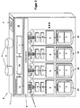
- FIG. 1 shows a schematic representation of an electrical energy storage E, which is surrounded by a housing 1, which is preferably vehicle-specific for releasably fixed implementation of an electric vehicle.
- a housing 1 which is preferably vehicle-specific for releasably fixed implementation of an electric vehicle.
- two contact electrodes 2 are provided for picking up an electrical useful voltage U and an interface 3 via which the information relating to the energy store can be transmitted to an external change station (not shown). This will be discussed in detail below.
- FIG. 1 shows an opened housing state.
- the four energy storage cells are representative of a large variety of energy storage cells.
- Each individual energy storage cell has to power power transfer terminal contacts 5, which are detachably connected to a provided within the housing 1 contacting unit 6 in electrical contact.
- each individual energy storage cell has a data memory 7, which is permanently connected to the energy storage cell is.
- the data memory 7 has at least one dynamic readable and writable data memory 7 'in which dynamic charge state information can be stored by the respective energy storage cell. For detecting the state of charge is in the in FIG.
- a cell voltage measuring unit 8 assigned to each individual energy storage cell is provided, which is connected via an interface 9 to the data memory 7, 7 'and via which the charge state information is transferred to the readable and writable data memory 7' and stored there.
- the individual energy storage cells 41 to 44 are connected via the contacting unit 6 to a control unit 10 which, inter alia, has a microprocessor 11 which, for example, carries out the cell voltage measurement provided for each energy storage cell and also for the dynamic storage of the charge state information determined per energy storage cell into the data memory 7 '.
- a control unit 10 which, inter alia, has a microprocessor 11 which, for example, carries out the cell voltage measurement provided for each energy storage cell and also for the dynamic storage of the charge state information determined per energy storage cell into the data memory 7 '.
- the current state of the individual energy storage cells characterizing sensors S, in the form of a temperature sensor and an expansion sensor whose sensor signals via the microprocessor 11 together with the state of charge information in the data memory. 7 'be transferred for storage.
- a cell monitoring unit 12 likewise provided in the control unit 10, the sensor-related combination of all cell-specific status information, ie state of charge, temperature and extent, which are subjected to a monitoring, takes place, so that it is checked whether the individual measured cell parameters each lie within a predefinable tolerance range. If corresponding deviations occur, suitable countermeasures must be taken, for example, by specifically changing the discharge in the case of a corresponding energy storage cell, or else the charging process is correspondingly adapted to the current cell state. This is ensured by a control unit 13 which carries out at least the discharging process of the individual energy storage cells as a function of criteria predetermined by the cell monitoring unit 12.
- the data memory 7 also has a static, ie only a readable data memory 7 "containing at least one information identifying the energy storage cell, the conclusions on the type of cell as well as their arrangement within the electrical energy storage allows.
- each individual energy storage cell has completely autonomous information that is required for an individual treatment or use of the energy storage cell as part of a discharge and charging process.
- the information stored in the data memory 7 it is possible, on the one hand, to identify the energy storage cell and, moreover, to qualify it on the basis of its utilization history with regard to the state of charge quality and the expected service life.
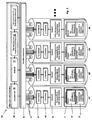
- FIG. 2 shows an expanded example of an electrical energy storage, which also in a housing 1, a plurality of individual energy storage cells 41 'to 44' provides, in contrast to the example in FIG. 1 additionally provide a sensor S and a microcontroller 14.
- Each individual energy storage cell 41 'to 44 'thus represents a completely autonomous energy storage cell unit, which is able to detect the current cell voltage by means of an "onboard" sensor S with a cell voltage meter, the cell internal temperature by means of a temperature sensor and the cell internal pressure with the aid of an expansion sensor, preferably in the form of a strain gauge.
- the sensor system S is controlled via a microcontroller 14, which is likewise mounted on or within the housing 1 to the energy storage cell 41 ', 42', 43 ', 44', the sensor data generated by the sensor system S being readable and writable Data memory 7 'transferred and stored.
- the data memory 7 'thus contains information that reflects the current state of charge, the so-called vital data in the form of temperature and internal pressure, and the resulting cell history. Furthermore, in the data memory 7 in the region of the static data storage part 7 "the respective energy storage cell identifying information containing references to the manufacturer, the manufacturer's date, usage information, etc.
- a control unit 10 ensures controlled data acquisition and evaluation of the information readable from the data memories 7 of each energy storage cell information by means of a microprocessor 11, which is in communication with a monitoring unit 12 ', which in turn is connected to a control unit 13 which at least the discharge of the individual energy storage cells depending on sides of the evaluation unit 12 'provided energy storage cells specific criteria.
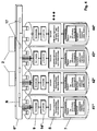
- FIG. 3 is a charging station 15 for charging the in FIG. 2 described energy storage cells 41 'to 44'. To avoid repetition, already explained components are provided with the already introduced reference numerals.
- individually charged energy storage cells 41 'to 44' are read from the respective data storage 7 all information and evaluated within the existing in the charging station 15 control unit 10 '. This is likewise done with the aid of a microprocessor 11 and a monitoring and evaluation unit 12 'connected thereto. Depending on the respective usage history as well as the respective current state of charge of an energy storage cell, an individual loading thereof is controlled or controlled by a control unit 13, which is in communication with the charging electronics 16 of the charging station 15.
- each individual energy storage cell 41 ', 42', 43 ', 44' which describes both the history of use and the current state, allows the charging process to be carried out very quickly and cell-specifically, especially since time-consuming and complicated calibration procedures are involved individual energy storage cell can be avoided. In this way, it is also possible to quickly determine whether to be charged energy storage cells can be subjected to a further charging or to be replaced due to detected errors or aging-related degradation.
- the individual trained as standard modules energy storage cells can be removed from the respective electrical energy storage modular, whereas value-determining components, such as the crash-trained housing 1, the powerful electronic components, such as the contacting unit 6 and control unit 10th as well as an optional within the housing 1 to be provided cooling device within the electrical energy storage. It can thus be ensured that production-specific energy stores remain unchanged in their essential value-determining components. It is only necessary to replace the individual standardized energy storage cells accordingly at a change station.
- FIG. 4 illustrated solution according to electrical energy storage requires the use of intelligently constructed individual energy storage cells 41 ", 42", 43 “, 44”, which are connected via detachable electrical contact 5 "only with an electrical contacting unit 6", in turn, the electrical contact electrodes 2 to attack the useful voltage U provides.
- the electrical contacts 5 "for modular insertion and removal of the individual energy storage cells 41", 42 “, 43", 44 “in or out of the cell network provide both separate connection contacts for the power supply and the data exchange, as with the energy storage cells 41 ", 42” and 43 "is the case, or in a particularly advantageous manner, only two contact poles, via which both the Zellennutzspannnung and the data can be tapped, as in the case of the energy storage cell 44" is indicated eg a modulated "power-line communication", separate and additional lines and contacts for a data interface can be completely eliminated, leaving only the two poles of the energy storage cells themselves as the only electrically conductive contact points, see energy storage cell 44 ".
- microcontroller 14 the tasks of the previous, central control unit (10, 10 ') in terms of battery management.
- each individual energy storage cell represents a self-sufficient and intelligently monitored energy storage cell, which makes its data available to all other energy storage cells in the network via a network N realized by the contacting unit 6 "In the context of this intelligent network N, comparable to" cloud computing ", the entire energy storage operation, ie discharging and charging with respect to each individual energy storage cell, can be carried out within the framework of an adaptive, rule based learning network.
- the individual discharging or charging of individual energy storage cells in the network N requires an actively controlled connection function
- Such function can be realized by explicitly controllable physical, electronic or inductive switch 17 within the network N. This greatly improves and simplifies the battery cell management, in particular in the case of non-regular operating states individual cells (safety cases).
Abstract
Description
Die Erfindung bezieht sich auf einen elektrischen Energiespeicher mit Kontaktelektroden zumindest zum Abgriff einer elektrischen Nutzspannung, einer Vielzahl von Energiespeicherzellen, die über eine gemeinsame Kontaktierungseinheit unter Zwischenschaltung einer Kontrolleinheit zur Beeinflussung zumindest eines Entladevorganges der einzelnen Energiespeicherzellen mit den Kontaktelektroden verbunden sind.The invention relates to an electrical energy store with contact electrodes at least for tapping a useful electrical voltage, a plurality of energy storage cells, which are connected via a common contacting unit with the interposition of a control unit for influencing at least one discharge of the individual energy storage cells with the contact electrodes.
Auf dem Gebiet elektromobiler Fortbewegung im Individualverkehr nehmen modulare elektrische Energiespeicher eine zentrale Rolle ein, zumal sie wesentlich mitbestimmend für die Kommerzialisierung von Elektrofahrzeugen sind.Modular electrical energy storage systems play a central role in the field of electromobility in private transport, especially as they are a major factor in the commercialization of electric vehicles.
Typischerweise bestehen elektrische Energiespeicher, sog. Sekundärbatterien, für Elektrofahrzeuge aus einem fest verdrahteten Verbund einzelner Energiezellen, die zum Abgriff der elektrischen Nutzspannung sowie auch zum Wiederaufladen mit einem Batteriemanagementsystem und vorzugsweise mit einer zusätzlichen Kühlung innerhalb eines Gehäuses untergebracht sind. Alle Komponenten sind fest miteinander verbaut und stellen ein sog. komplettes einheitliches Batteriepack dar.Typically, electrical energy storage, so-called secondary batteries for electric vehicles from a hard-wired composite of individual energy cells, which are housed for tapping the electrical utility voltage as well as for recharging with a battery management system and preferably with additional cooling within a housing. All components are permanently installed together and constitute a so-called complete uniform battery pack.
Derartige fest in einem Fahrzeug installierte Energiespeichersysteme benötigen für das Wiederaufladen, bspw. bei vollständiger Entladung, mehrere Stunden, wodurch sich die Akzeptanz derartiger Elektrofahrzeuge erheblich von konventionellen Fahrzeugen mit Verbrennungsmotoren unterscheidet, zumal ein typischer Betankungsvorgang wenige Minuten benötigt. Soll dies zugunsten der Elektromobilität geändert werden ist zumindest mittelfristig eine erhebliche Verkürzung des Ladevorganges oder alternativ ein schneller Wechsel des Energiespeichers unerlässlich.Such permanently installed in a vehicle energy storage systems need for recharging, for example. At full discharge, several hours, which the acceptance of such electric vehicles differs significantly from conventional vehicles with internal combustion engines, especially since a typical refueling process takes a few minutes. If this is to be changed in favor of electromobility, a significant shortening of the charging process or, alternatively, a quick change of the energy storage is indispensable, at least in the medium term.
Derzeit existieren Vorschläge, den Energiespeicher für Elektrofahrzeuge modulartig auszubilden und bedarfsweise, d. h. beim entladenen Energiespeicher gegen einen frisch aufgeladenen Energiespeicher an einer Wechselstation auszuwechseln. Ein derartiger Austauschvorgang benötigt in etwa den gleichen Zeitaufwand wie die Betankung eines konventionell angetriebenen Fahrzeuges, jedoch erfordert ein derartiges auf den Austausch modular ausgebildeter Energiespeicher beruhendes Energieversorgungskonzept für Elektrofahrzeuge standardisierte Energiespeichermodule. Die zu erwartende Produktvielfalt auf dem stets größer werdenden Elektromobilmarkt wird dieser Forderung erwartungsgemäß jedoch nicht gerecht werden, zumal gerade der Energiespeichertechnologie eine technologische Schlüsselrolle zukommen wird, die mit jener vergleichbar ist, die derzeit für die Verbrennungsmotoren gilt. Erwartungsgemäß wird jedoch Güte und Qualität künftiger Elektromobile nicht in erster Linie durch den elektromotorischen Antrieb, sondern federführend durch die Energiespeichertechnologie bestimmt sein. Es kann daher davon ausgegangen werden, dass sich die Energiespeichersysteme von unterschiedlichen Herstellern in puncto Qualität, Leistung und Effizienz unterscheiden werden. Sollte das vorstehend beschriebene Konzept, des Austausches von modulartig ausgebildeten Energiespeichern aufgrund des zeitlichen Vorteils durchsetzen, so wäre nach den bisherigen Überlegungen eine Bevorratung von aufgeladenen Energiespeichermodulen von unterschiedlichen Herstellern in den Wechselstationen die Folge wäre. Dies jedoch erfordert eine kaum realisierbare und finanzierbare Logistik.There are currently proposals to formulate the energy storage for electric vehicles modular and, if necessary, d. H. replace the discharged energy storage against a freshly charged energy storage at a changing station. Such an exchange process requires approximately the same amount of time as the refueling of a conventionally driven vehicle, but requires such based on the exchange of modular energy storage energy supply concept for electric vehicles standardized energy storage modules. As expected, however, the expected product diversity on the steadily increasing e-mobility market will not do justice to this requirement, especially since energy storage technology will play a key technological role that is comparable to that which currently applies to internal combustion engines. As expected, however, the quality and quality of future electric vehicles will not be determined primarily by the electromotive drive, but rather by the energy storage technology. It can therefore be expected that the energy storage systems will differ from different manufacturers in terms of quality, performance and efficiency. If the above-described concept of exchanging module-shaped energy stores prevails due to the time advantage, then, according to previous considerations, the storage of charged energy storage modules from different manufacturers in the change stations would be the result. However, this requires a hardly realizable and affordable logistics.
Derzeit auf dem Markt befindliche elektrische Energiespeicher bestehen aus einer Vielzahl einzelner Energiezellen, bspw. in Form von Lithiumionen- und/oder Lithiumpolymerzellen, die über eine gemeinsame Kontaktierungseinheit zur Erhöhung der Leistungskapazität in Reihe oder parallel zueinander geschaltet sind, so dass an den Kontaktelektroden des Energiespeichers eine elektrische Nutzspannung in der Größenordnung von einigen 100 V und ein Nennstrom in der Größenordnung von einigen 100 A abgreifbar sind. Es ist bekannt, dass unerwünschte Zustände während des Ladens und Entladens auftreten können, wenn eine Energiespeicherzelle oder einige Energiespeicherzellen im elektrischen Verbund mit allen übrigen Energiespeicherzellen wesentliche Eigenschaften zeigt bzw. zeigen, die erheblich von denen anderer Energiespeicherzellen abweichen. Übersteigt bspw. die Ladespannung an einer anormalen Energiespeicherzelle eine vorgegebene Maximalspannungsgrenze, so kann ein derartiger Überspannungszustand die Zelle beschädigen und die Lebensdauer der Zelle sowie weiterer Zellen im elektrischen Verbund erheblich verringern. Aus diesem Grunde sehen moderne elektrische Energiespeichersysteme eine, die einzelnen Energiespeicherzellen überwachende Kontrolleinheit, auch als Batteriemanagementsystem bezeichnet, vor, die den Entlade- sowie auch Ladevorgang der einzelnen Energiespeicherzellen überwacht.Electric energy stores currently on the market consist of a large number of individual energy cells, for example in the form of lithium-ion and / or lithium-ion batteries Lithium polymer cells, which are connected via a common contacting unit for increasing the power capacity in series or in parallel, so that at the contact electrodes of the energy storage an electrical utility voltage in the order of several 100 V and a rated current in the order of several 100 A can be tapped. It is known that undesirable states during charging and discharging can occur when an energy storage cell or some energy storage cells in electrical connection with all other energy storage cells show or show essential properties that differ significantly from those of other energy storage cells. If, for example, the charging voltage at an abnormal energy storage cell exceeds a predetermined maximum voltage limit, such an overvoltage condition can damage the cell and considerably reduce the service life of the cell and of other cells in the electrical network. For this reason, see modern electrical energy storage systems, the individual energy storage cells monitoring control unit, also referred to as a battery management system before, which monitors the discharge and charging of the individual energy storage cells.
Aus der
Der
Aus
Aus
Der Erfindung liegt die Aufgabe zugrunde einen elektrischen Energiespeicher mit Kontaktelektroden zumindest zum Abgriff einer elektrischen Nutzspannung, einer Vielzahl von Energiespeicherzellen, die über eine gemeinsame Kontaktierungseinheit unter Zwischenschaltung einer Kontrolleinheit zur Beeinflussung zumindest eines Entladevorganges der einzelnen Energiespeicherzellen mit den Kontaktelektroden verbunden sind, wobei in jeder Energiespeicherzelle zumindest ein lese- und schreibfähiger Datenspeicher sowie die Kontrolleinheit integriert ist, wobei in jeder Energiespeicherzelle eine den aktuellen Ladezustand der Energiespeicherzelle dynamisch erfassende Einheit integriert ist, die einen Mikrocontroller sowie einen Zellspannungsmesssensor umfasst und dynamisch Ladezustandsinformationen von der Energiespeicherzelle erstellt und diese in den lese- und schreibfähigen Datenspeicher zur Erstellung und Abspeicherung einer Ladezustandshistorie überträgt,wobei die Kontrolleinheiten aller Energiespeicherzellen über die Kontaktierungseinheit miteinander verbunden sind und ein Netzwerk bilden, über das Informationen zwischen den einzelnen Kontrolleinheiten austauschbar sind zu Zwecken einer Beeinflussung zumindest des Entladevorganges, und wobei jede Energiespeicherzelle über elektrische Anschlusskontakte verfügt, die lösbar mit der Kontaktierungseinheit verbindbar sind, derart weiterzubilden, dass eine individuelle Handhabung einzelner Energiespeicherzellen insbesondere für den Aufladevorgang der Zellen möglich wird, um den Austausch bzw. Wechsel der Energiespeicherzellen innerhalb eines elektrischen Energiespeichers zu vereinfachen sowie auch zeitlich zu verkürzen. Insbesondere sollen Maßnahmen getroffen werden, durch die die Wertbestimmenden Komponenten eines Energiespeichers trotz Auswechseln der Energiespeicherzellen im Energiespeicher erhalten bleiben. So soll insbesondere die Akzeptanz von Batteriewechselsystemen insbesondere auf dem Elektrofahrzeugsektor verbessert werden.The invention is based on the object of an electrical energy storage with contact electrodes at least for tapping a useful electrical voltage, a plurality of energy storage cells, which are connected via a common contacting unit with the interposition of a control unit for influencing at least one discharge of the individual energy storage cells with the contact electrodes, wherein in each energy storage cell at least one readable and writable data memory and the control unit is integrated, wherein in each energy storage cell, a current state of charge of the energy storage cell dynamically detecting unit is integrated, the one Microcontroller and a cell voltage measuring sensor and dynamically generates state of charge information from the energy storage cell and this transmits in the readable and writable data memory for creating and storing a state of charge state, the control units of all energy storage cells are connected to each other via the contacting unit and form a network on the information between the individual control units are interchangeable for purposes of influencing at least the discharge process, and wherein each energy storage cell has electrical connection contacts, which are detachably connectable to the contacting, such further that individual handling of individual energy storage cells, in particular for the charging process of the cells is possible to the exchange or to change the energy storage cells within an electrical energy storage to simplify as well as to shorten the time. In particular, measures are to be taken by which the value-determining components of an energy store are retained despite replacement of the energy storage cells in the energy store. In particular, the acceptance of battery replacement systems is to be improved, especially in the electric vehicle sector.
Die Lösung der der Erfindung zugrunde liegenden Aufgabe ist im Anspruch 1 angegeben. Den Lösungsgedanken vorteilhaft weiterbildende Merkmale sind Gegenstand der Unteransprüche sowie der weiteren Beschreibung insbesondere unter Bezugnahme auf ein Ausführungsbeispiel gemäß
Lösungsgemäß ist ein elektrischer Energiespeicher mit Kontaktelektroden zumindest zum Abgriff einer elektrischen Nutzspannung, einer Vielzahl von Energiespeicherzellen, die über eine gemeinsame Kontaktierungseinheit unter Zwischenschaltung einer Kontrolleinheit zur Beeinflussung zumindest eines Entladevorganges der einzelnen Energiespeicherzellen mit den Kontaktelektroden verbunden sind, wobei in jeder Energiespeicherzelle zumindest ein lese- und schreibfähiger Datenspeicher sowie die Kontrolleinheit integriert ist, wobei in jeder Energiespeicherzelle eine den aktuellen Ladezustand der Energiespeicherzelle dynamisch erfassende Einheit integriert ist, die einen Mikrocontroller sowie einen Zellspannungsmesssensor umfasst und dynamisch Ladezustandsinformationen von der Energiespeicherzelle erstellt und diese in den lese- und schreibfähigen Datenspeicher zur Erstellung und Abspeicherung einer Ladezustandshistorie überträgt, wobei die Kontrolleinheiten aller Energiespeicherzellen über die Kontaktierungseinheit miteinander verbunden sind und ein Netzwerk bilden, über das Informationen zwischen den einzelnen Kontrolleinheiten austauschbar sind zu Zwecken einer Beeinflussung zumindest des Entladevorganges, und wobei jede Energiespeicherzelle über elektrische Anschlusskontakte verfügt, die lösbar mit der Kontaktierungseinheit verbindbar sind, dadurch ausgebildet, dass die Kontaktierungseinheit von den Kontrolleinheiten aktiv ansteuerbare Schaltelemente aufweist, die ein Zu- oder Abschalten einzelner Energiespeicherzellen zumindest für den Entladevorgang ermöglichen. Jede einzelne Energiespeicherzelle stellt somit eine mit dem Datenspeicher untrennbare Baueinheit dar, wobei es für die technische Funktionalität der Energiespeicherzelle nicht von Bedeutung ist, ob der Datenspeicher oberflächig sichtbar, auf der Energiespeicherzelle aufgebracht oder als integrale Komponente innerhalb der Energiespeicherzelle verbaut ist. Die elektrischen Anschlusskontakte jeder einzelnen Energiespeicherzelle weisen vorzugsweise ein standardisiertes, verpolungssicheres Layout auf, das eine fehlerhafte Kontaktierung, insbesondere in Fällen, in denen die einzelnen Energiespeicherzellen automatisch, bspw. mit einem Handhabungsroboter manipuliert werden, auszuschließen vermag. Dabei verfügt das für die Leistungsübertragung als auch für die Kommunikation dienende Kontaktierungssystem über eine hohe Robustheit und ist für hohe Steckzyklen ausgelegt. Alternativ zur getrennten Ausbildung der für den Datenaustausch vorgesehenen lösbaren Schnittstelle und den elektrischen Anschlusskontakten seitens der Energiespeicherzellen ist es unter Nutzung geeigneter Modulationstechniken möglich den Datenaustausch und den Nutzenergieaustausch über gemeinsam nutzbare elektrische Kontaktstellen zu realisieren. Derartig ausgebildete Energiespeicherzellen verfügen somit lediglich über zwei elektrische Kontaktstellen, die den beiden elektrischen Polen der Energiespeicherzellen entsprechen, über die sowohl die Nutzspannung als auch die Datenspeicherinhalte abgegriffen werden können. Dies trägt zur Kostenreduzierung sowie auch zu einer Verbesserung der Robustheit der Energiespeicherzelle bei, die bei der modularen Handhabung während eines erforderlichen Austausches aus dem Energiespeicherverbund durchaus mechanische Belastungen erfährt.According to the invention, an electrical energy store with contact electrodes is at least connected to an electrical useful voltage, a plurality of energy storage cells, which are connected via a common contacting unit with the interposition of a control unit for influencing at least one discharging process of the individual energy storage cells with the contact electrodes, wherein at least one read in each energy storage cell. and writable data storage and the control unit is integrated, wherein in each energy storage cell, the current state of charge of the Is energy storage cell dynamically acquiring unit integrated, which comprises a microcontroller and a cell voltage measuring sensor and dynamically creates charge status information from the energy storage cell and that in the read and write capability data storage for creating and storing a charge state history übertr ä gt wherein the control units of all energy storage cells on the contacting interconnected are and form a network through which information between the individual control units are interchangeable for purposes of influencing at least the discharge process, and wherein each energy storage cell has electrical connection contacts that are detachably connectable to the contacting unit, formed by the contacting unit of the control units active having controllable switching elements, which enable a connection or disconnection of individual energy storage cells at least for the discharge process n. Each individual energy storage cell thus represents an inseparable with the data storage unit, where it is not important for the technical functionality of the energy storage cell, whether the data storage surface visible, applied to the energy storage cell or installed as an integral component within the energy storage cell. The electrical connection contacts of each individual energy storage cell preferably have a standardized, reverse polarity-safe layout, which is able to exclude a faulty contact, in particular in cases where the individual energy storage cells are manipulated automatically, for example. With a handling robot. The contacting system used for the power transmission as well as for the communication has a high robustness and is designed for high mating cycles. As an alternative to the separate design of the detachable interface provided for the data exchange and the electrical connection contacts on the part of the energy storage cells, it is possible, using suitable modulation techniques, to realize the data exchange and the useful energy exchange via jointly usable electrical contact points. Such trained energy storage cells thus have only two electrical contact points, which correspond to the two electrical poles of the energy storage cells, on the both the useful voltage and the data storage contents can be tapped. This contributes to the cost reduction as well as to an improvement in the robustness of the energy storage cell, which experiences mechanical stresses during the required exchange during the required exchange from the energy storage network.
Aus dem lese- und schreibfähigen Datenspeicher der Energiespeicherzelle können die dynamisch erfassten Ladezustansinformationen in Form einer Ladezustandshistorie jederzeit ausgelesen werden. Der Begriff "Ladezustandshistorie" bezeichnet den zeitlichen Verlauf von Entlade- und Ladezyklen einer Energiespeicherzelle und umfasst somit Informationen über die bisherige Nutzung der Energiespeicherzelle, bspw. zurückliegende Lade- und Entladezyklen.From the readable and writable data memory of the energy storage cell, the dynamically detected charging state information in the form of a state of charge state history can be read out at any time. The term "state of charge history" designates the time course of discharge and charge cycles of an energy storage cell and thus includes information about the previous use of the energy storage cell, for example. Previous charging and discharging cycles.
Darüber hinaus befinden sich auf dem Datenspeicher die jeweilige Energiespeicherzelle individualisierende Informationen, wie bspw. Zellentyp, Zellenname, Herstellungsdatum, Hersteller etc.. Mit Hilfe sämtlicher dezentral auf jeder einzelnen Energiespeicherzelle abgespeicherten Informationen ist eine zuverlässige Analyse bzw. Bewertung jeder einzelnen Energiespeicherzelle im Hinblick auf ihren gegenwärtigen Ladezustand, ihre allgemeine Zustandsbeschaffenheit sowie die zu erwartende Restlebensdauer möglich. Unter Nutzung der in dem jeweiligen Datenspeicher abgelegten und auslesbaren Informationen kann sowohl zu Zwecken einer kontrollierten Entladung als auch Wiederaufladung die jeweilige Energiespeicherzelle durch die im elektrischen Energiespeicher vorgesehene Kontrolleinheit optimal und individuell angesteuert werden.In addition, the respective energy storage cell is on the data storage individualizing information, such as. Cell type, cell name, date of manufacture, manufacturer, etc. With the help of all locally stored on each energy storage cell information is a reliable analysis or evaluation of each energy storage cell in terms of their current state of charge, their general condition and the expected remaining life possible. By using the information stored and readable in the respective data memory, the respective energy storage cell can be optimally and individually controlled by the control unit provided in the electrical energy store both for purposes of controlled discharging and recharging.
Tritt bspw. der Fall auf, dass innerhalb eines elektrischen Energiespeichers eine Energiespeicherzelle hinsichtlich ihrer Ladekapazität von den Ladekapazitäten aller übrigen im Energiespeicher vorhandenen Energiespeicherzellen abweicht, so kann dies mit Hilfe der Kontrolleinheit bei einer kontrollierten Entladung entsprechend berücksichtigt werden, bspw. durch eine Minderentladung der betreffenden Energiespeicherzelle oder es werden anderweitige Maßnahmen getroffen.Occurs, for example, the case that within an electrical energy storage an energy storage cell deviates in terms of their charge capacity of the charging capacity of all other energy storage cells existing in the energy storage, so this can be taken into account by means of the control unit in a controlled discharge accordingly, for example. By a minor discharge of the relevant Energy storage cell or other measures are taken.
In einer bevorzugten Ausführungsform für einen elektrischen Energiespeicher sind weitere Sensoren innerhalb der einzelnen Energiespeicherzellen integriert, die den aktuellen Zustand der jeweiligen Energiespeicherzelle überwachen und deren Sensorsignale entsprechend im Datenspeicher aufgezeichnet werden. So eignet sich hierzu insbesondere ein im Inneren der Energiespeicherzelle integrierter Temperatursensor, mit dem es möglich ist, die Energiezelleninnentemperatur dynamisch zu erfassen. Hierdurch können Überhitzungserscheinungen verzögerungsfrei innerhalb der Energiespeicherzelle erfasst werden, denen mit geeigneten Kontrollmaßnahmen rechtzeitig entgegengetreten werden können, bspw. durch Vorsehen und Aktivieren einer im Inneren des elektrischen Energiespeichers vorgesehenen Kühlung. Alternativ oder in Kombination mit dem Temperatursensor dient ein am oder innerhalb der Energiespeicherzelle integrierter Ausdehnungssensor zur dynamischen Erfassung des Energiezelleninnendruckes, durch den Zellenfehlfunktionen bereits im Frühstadium detektiert werden können. So führt bspw. Eine zelleninterne Gasbildung oder Flüssigkeitsaustritt zu einer signifikanten Zellinnendruckänderung.In a preferred embodiment for an electrical energy store, further sensors are integrated within the individual energy storage cells which monitor the current state of the respective energy storage cell and whose sensor signals are correspondingly recorded in the data memory. For this purpose, in particular a temperature sensor integrated in the interior of the energy storage cell is suitable, with which it is possible to dynamically detect the energy cell internal temperature. As a result, overheating phenomena can be detected without delay within the energy storage cell, which can be counteracted in a timely manner by suitable control measures, for example by providing and activating cooling provided in the interior of the electrical energy store. Alternatively or in combination with the temperature sensor, an expansion sensor integrated on or inside the energy storage cell serves for the dynamic detection of the internal energy cell pressure, by means of which cell malfunctions can be detected already at an early stage. For example, cell-internal gas formation or liquid leakage leads to a significant internal cell pressure change.
Der neben dem vorstehend erläuterten lese- und schreibfähigen Datenspeicher in der Energiespeicherzelle integrierte Mikrocontroller, speichert sämtliche erfassten Sensordaten bzw. Informationen auf den Datenspeicher in zeitlich geordneter Weise ab. Der Mikrocontroller ist auch in der Lage sämtliche sensorisch erfassten Daten und Informationen nach technischer Relevanz zu bewerten und in einer gefilterten und/oder komprimierten Form letztlich abzuspeichern, um auf diese Weise nur jene Ladungszustandsrelevanten Informationen zu erhalten, die für eine zuverlässige Bewertung des aktuellen Ladezustands erforderlich sind. Auf diese weise kann Kosten- und Energieaufwendiger Speicherplatz eingespart werden.The microcontroller, which is integrated in the energy storage cell in addition to the above-described readable and writable data memory, stores all detected sensor data or information on the data memory in a time-ordered manner. The microcontroller is also able to evaluate all sensory acquired data and information according to technical relevance and ultimately store it in a filtered and / or compressed form, in order to obtain in this way only those charge state relevant information required for a reliable assessment of the current state of charge are. In this way, costly and energy-consuming storage space can be saved.
Zusätzlich zu den den Ladezustand beschreibenden Informationen, die sich letztlich aus der chronologischen Erfassung der Zellenspannungswerte jeweils für eine Energiespeicherzelle ergeben und die aktuelle Ladekapazität beschreiben, können die an einer Energiespeicherzelle sensorisch erfassten Informationen, wie Zellspannung, Temperatur und Innendruck, für eine weiterführende Bewertung der Energiespeicherzelle verwendet werden, nämlich zur Bestimmung des Alterungszustandes der Energiespeicherzelle. Der Alterungszustand einer Energiespeicherzelle quantifiziert die mit zunehmendem Alter der Energiespeicherzelle degradierende Ladekapazität und ermöglicht zumindest eine Abschätzung über die technisch nutzbare Restlebenddauer, d.h. Anzahl von technisch noch nutzbaren Lade- und Entladezyklen. In Kenntnis des Alterungszustandes der Vielzahl im Energiespeicher eingesetzten Energiespeicherzellen lässt sich bspw. eine logistisch wertvolle Information dahingehend ableiten, wie viel neue Energiespeicherzellen zu bevorraten sind, um sie bei Bedarf anstelle von "verbrauchten" Energiespeicherzellen einzusetzen.In addition to the information describing the state of charge, which ultimately result from the chronological recording of the cell voltage values for an energy storage cell and describe the current charge capacity, the information sensed on an energy storage cell, such as cell voltage, temperature and internal pressure, can be used for further evaluation of the energy Energy storage cell can be used, namely for determining the aging state of the energy storage cell. The aging state of an energy storage cell quantifies the charging capacity degrading with increasing age of the energy storage cell and enables at least an estimation of the technically usable remaining service life, ie number of technically usable charging and discharging cycles. Knowing the state of aging of the plurality of energy storage cells used in the energy storage can be, for example, a logistically valuable information derived to determine how much new energy storage cells are to stockpile to use them instead of "spent" energy storage cells.
Die vorstehend erläuterten Ausführungsformen ermöglichen jeweils eine dezentrale, zellenbasierte Datenhaltung in einem Datenspeicher, der in einer Energiespeicherzelle integriert ist, wodurch sich die Möglichkeit eines individuellen Wechsels aller oder einzelner Energiespeicherzellen aus einem elektrischen Energiespeicher eröffnet.The above-described embodiments each allow a decentralized, cell-based data storage in a data memory which is integrated in an energy storage cell, which opens up the possibility of an individual change of all or individual energy storage cells from an electrical energy store.
Der Energiespeicher sieht so die Ausbildung von einer Vielzahl über die Kontaktierungseinheit zu einem Netzverbund miteinander verbundener "intelligenter" Energiespeicherzellen vor, in denen jeweils die Kontrolleinheit dezentral vorgesehen ist. Derartig ausgebildete Energiespeicherzellen, in denen zumindest ein lese- und schreibfähiger Datenspeicher sowie die Kontrolleinheit, vorzugsweise in Form eines Mikrokontrollers integriert sind, ermöglicht den Aufbau von nahezu beliebig erweiterbaren Energiespeichersystemen, in denen die im Netzwerkverbund miteinander verschalteten einzelnen Energiespeicherzellen miteinander in einem Datenaustausch stehen und somit den Entlade- oder Ladevorgang adaptiv, d.h. Fallabhängig vom Ladezustand einer jeden einzelnen Energiespeicherzelle beeinflussen können.The energy store thus provides for the formation of a multiplicity of "intelligent" energy storage cells interconnected via the contacting unit to form a network of interconnected "intelligent" energy storage cells, in each of which the control unit is provided in a decentralized manner. Such trained energy storage cells in which at least one readable and writable data storage and the control unit, preferably integrated in the form of a microcontroller, allows the construction of almost any expandable energy storage systems in which the network interconnected interconnected individual energy storage cells communicate with each other in a data exchange and thus the unloading or charging adaptive, ie Depending on the state of charge of each individual energy storage cell can influence.
Die Kontaktierungseinheit ist mit von der Kontrolleinheit bzw. von den Kontrolleinheiten aktiv ansteuerbaren Schaltelementen, bspw. in Form von physikalischen, elektronischen oder induktiven Schaltern bzw. An-/Abkopplungselementen, ausgestattet, die ein Zu- oder Abschalten einzelner Energiespeicherzellen zumindest für den Entladevorgang ermöglichen.The contacting unit is provided with switching elements which can be actively activated by the control unit or by the control units, for example in the form of physical, electronic or inductive switches or coupling / decoupling elements, equipped to enable or disable individual energy storage cells at least for the discharge process.
Ferner sei bspw. angenommen, dass ein lösungsgemäß ausgebildeter elektrischer Energiespeicher in einem fahrzeugspezifischen, crashsicher ausgebildeten Gehäuse untergebracht ist und zur elektrischen Energieversorgung für ein Elektrofahrzeug dient. Bei einem erforderlichen Austausch bzw. Wechsel eines elektrischen Energiespeichers wird der erneut aufzuladende elektrische Energiespeicher aus dem Fahrzeug entnommen. Ein bereits in der Wechselstation bevorrateter, aufgeladener Energiespeicher wird in das Fahrzeug eingesetzt, so dass das Fahrzeug innerhalb weniger Minuten die Wechselstation verlassen kann. Aus dem, aus dem Fahrzeug entnommene Energiespeicher werden die leeren Energiespeicherzellen entnommen, vorzugsweise automatisiert mit Hilfe eines Roboters, und gegen bereits voll aufgeladene Energiespeicherzellen ausgetauscht, die in die entsprechenden Kontaktplätze eingefügt werden. Die entleerten Energiespeicherzellen werden einer Prüfung und einem anschließenden Ladevorgang unterzogen, bei dem der Ladevorgang unter Berücksichtigung der aus dem jeweiligen Datenspeicher entnommenen Energiespeicherzelleninformation zellenspezifisch vorgenommen wird.Furthermore, it is assumed, for example, that a solution according to trained electrical energy storage is housed in a vehicle-specific, crash-proof housing and is used for electrical power supply for an electric vehicle. In a required replacement or change of an electrical energy storage of rechargeable electrical energy storage is removed from the vehicle. An already stored in the changing station, charged energy storage is used in the vehicle, so that the vehicle can leave the changing station within a few minutes. From the, removed from the vehicle energy storage, the empty energy storage cells are removed, preferably automatically with the help of a robot, and exchanged for already fully charged energy storage cells, which are inserted into the corresponding contact points. The emptied energy storage cells are subjected to a test and a subsequent charging process, in which the charging process is carried out in a cell-specific manner taking into account the energy storage cell information taken from the respective data memory.
Das Aufladen der Energiespeicherzellen muss jedoch nicht nur durch eine externe Ladestation, wie vorstehend erläutert, erfolgen. Sie kann auch bereits im laufenden Fahrzeugbetrieb durch das Rückspeisen von aufgenommener Energie des mobilen Fahrzeuges, z.B. Bremsenergie im Generatorbetrieb der Antriebe, gezielt einzelnen dafür geeigneten Energiespeicherzellen im Speicherverbund zugeführt werden.However, the charging of the energy storage cells need not be done only by an external charging station, as explained above. It can also already during ongoing vehicle operation by the recovery of absorbed energy of the mobile vehicle, such as braking energy in the generator mode of the drives, selectively supplied to each suitable energy storage cells in the storage network.
Die Erfindung wird nachstehend ohne Beschränkung des allgemeinen Erfindungsgedankens anhand eines Ausführungsbeispiels gemäß
- Fig. 1
- erste einfache Form für einen elektrischen Energiespeicher,
- Fig. 2
- erweiterte zweite Form eines elektrischen Energiespeichers,
- Fig. 3
- Illustration eines Ladevorganges von entleerten Energiespeicherzellen sowie
- Fig. 4
- Lösungsgemäße Ausführungsform für einen intelligenten Energiespeicher.
- Fig. 1
- first simple form for an electrical energy storage,
- Fig. 2
- advanced second form of electrical energy storage,
- Fig. 3
- Illustration of a charging process of depleted energy storage cells as well
- Fig. 4
- Solution-oriented embodiment for an intelligent energy storage.
Das Gehäuse 1 ist mit einem Deckel (nicht dargestellt) verschließbar,
Die einzelnen Energiespeicherzellen 41 bis 44 sind über die Kontaktierungseinheit 6 mit einer Kontrolleinheit 10 verbunden, die u. a. einen Mikroprozessor 11 aufweist, der bspw. für die Durchführung der pro Energiespeicherzelle vorgesehenen Zellspannungsmessung sorgt sowie auch für die dynamische Abspeicherung der pro Energiespeicherzelle ermittelten Ladezustandsinformationen in den Datenspeicher 7'. Darüber hinaus befinden sich innerhalb des Gehäuses 1 im Bereich der Energiespeicherzellen 41 bis 44 weitere, den aktuellen Zustand der einzelnen Energiespeicherzellen charakterisierende Sensoren S, in Form eines Temperatursensors sowie auch eines Ausdehnungssensors, deren Sensorsignale über den Mikroprozessor 11 gemeinsam mit den Ladezustandsinformationen in den Datenspeicher 7' zur Abspeicherung übertragen werden. Im Rahmen einer ebenfalls in der Kontrolleinheit 10 vorgesehenen Zellenüberwachungseinheit 12 erfolgt die sensorische Zusammenführung aller zellenspezifischer Zustandsinformationen, d. h. Ladezustand, Temperatur und Ausdehnung, die einer Überwachung dahingehend unterzogen werden, so dass überprüft wird, ob die einzelnen gemessenen Zellenparameter jeweils in einem vorgebbaren Toleranzbereichen liegen. Treten entsprechende Abweichungen auf, so gilt es geeignete Gegenmaßnahmen zu treffen, indem bspw. die Entladung bei einer entsprechenden Energiespeicherzelle spezifisch geändert wird oder aber der Ladevorgang wird entsprechend auf den aktuellen Zellenzustand angepasst. Hierzu sorgt eine Steuereinheit 13, die zumindest den Entladevorgang der einzelnen Energiespeicherzellen in Abhängigkeit von seitens der Zellüberwachungseinheit 12 vorgegebenen Kriterien vornimmt. Neben dem bereits erwähnten lese- und schreibfähigen Datenspeicher 7' verfügt der Datenspeicher 7 auch über einen statischen, d. h. lediglich einen lesefähigen Datenspeicher 7", der zumindest eine die Energiespeicherzelle identifizierende Information enthält, die Rückschlüsse auf den Typ der Zelle sowie auch ihre Anordnung innerhalb des elektrischen Energiespeichers ermöglicht.The individual
Der technische Vorteil des Energiespeichers besteht darin, dass jede einzelne Energiespeicherzelle vollkommen autonom über sämtliche Informationen verfügt, die für eine individuelle Behandlung bzw. Nutzung der Energiespeicherzelle im Rahmen eines Entlade- sowie auch Ladevorganges erforderlich sind. Mit Hilfe der in dem Datenspeicher 7 abgelegten Informationen ist es zum einen möglich, die Energiespeicherzelle zu identifizieren und darüber hinaus anhand ihrer Nutzungshistorie im Hinblick auf Ladezustand Qualität und zu erwartender Lebensdauer zu qualifizieren. Dies eröffnet die Möglichkeit jede einzelne Energiespeicherzelle aus dem Verbund des elektrischen Energiespeichers zu entnehmen, bspw. mit Hilfe eines automatisierten Wechselsystems und einer Wiederaufladestation zuzuführen, die die Energiespeicherzelle unter Berücksichtigung der aus dem Datenspeicher auslesbaren Informationen sehr zellenspezifisch optimiert wieder auflädt.The technical advantage of the energy storage is that each individual energy storage cell has completely autonomous information that is required for an individual treatment or use of the energy storage cell as part of a discharge and charging process. With the aid of the information stored in the
Über die neben den Kontaktelektroden 2 am Gehäuse 1 angebrachte elektrische Schnittstelle 3 können sämtliche Informationen, die über den Mikroprozessor 11 aus den Datenspeichern 7 jeder einzelnen Energiespeicherzellen 41 bis 44 ausgelesen werden, an eine externe Auswerteeinheit bspw. an eine Wechselstation gesamtheitlich übergeben werden. In Abhängigkeit davon kann der Entnahme- sowie Aufladevorgang jeder einzelnen Energiespeicherzelle zellen- und zeitoptimiert vorgenommen werden.Via the
In gleicher Weise wie im vorstehend erläuterten Beispiel gemäß
In
Aus den über die Kontaktierungseinheit 6 mit der Ladestation 15 elektrisch verbundenen, einzeln aufzuladenden Energiespeicherzellen 41' bis 44' werden aus den jeweiligen Datenspeichern 7 sämtliche Informationen ausgelesen und im Rahmen der in der Ladestation 15 vorhandenen Kontrolleinheit 10' ausgewertet. Dies erfolgt gleichfalls mit Hilfe eines Mikroprozessors 11 und einer mit diesen verbundenen Überwachungs- und Auswerteeinheit 12'. In Abhängigkeit der jeweiligen Nutzungshistorie sowie auch des jeweils aktuellen Ladezustandes einer Energiespeicherzelle erfolgt eine individuelle Beladung derselben jeweils kontrolliert bzw. gesteuert durch eine Steuereinheit 13, die mit der Ladeelektronik 16 der Ladestation 15 in Verbindung steht.From the information about the contacting
Durch die von jeder einzelnen Energiespeicherzelle 41', 42', 43', 44' bereitgestellten Informationen, die sowohl die Nutzugshistorie bzw. Ladungshistorie als auch den aktuellen Zustand beschreiben, kann der Ladevorgang sehr schnell und zellenspezifisch durchgeführt werden, zumal zeitraubende und komplizierte Einmessvorgänge jeder einzelnen Energiespeicherzelle vermieden werden können. Auf diese Weise ist es ebenfalls schnell möglich festzustellen, ob zu ladende Energiespeicherzellen einem weiteren Ladevorgang unterzogen werden können oder aufgrund festgestellter Fehler oder alterungsbedingter Degradationen auszutauschen sind.The information provided by each individual energy storage cell 41 ', 42', 43 ', 44', which describes both the history of use and the current state, allows the charging process to be carried out very quickly and cell-specifically, especially since time-consuming and complicated calibration procedures are involved individual energy storage cell can be avoided. In this way, it is also possible to quickly determine whether to be charged energy storage cells can be subjected to a further charging or to be replaced due to detected errors or aging-related degradation.
Durch die dezentralisierte, d. h. zellenbasierte Datenhaltung, können die einzelnen als Standardmodule ausgebildete Energiespeicherzellen aus dem jeweiligen elektrischen Energiespeicher modular entnommen werden, wohingegen wertbestimmende Komponenten, wie bspw. das crashsicher ausgebildete Gehäuse 1, die leistungsfähigen Elektronikkomponenten, wie bspw. die Kontaktierungseinheit 6 sowie Kontrolleinheit 10 als auch eine optional innerhalb des Gehäuses 1 vorzusehende Kühlvorrichtung innerhalb des elektrischen Energiespeichers erhalten bleiben. Somit kann gewährleistet werden, dass herstellungsspezifische Energiespeicher in ihren wesentlichen wertbestimmenden Komponenten unverändert bleiben. Lediglich gilt es bei einer Wechselstation die einzelnen standardisierten Energiespeicherzellen entsprechend auszutauschen. Für die Praxis bedeutet dies, dass für den Nutzer eines Elektrofahrzeuges sichergestellt ist, dass beim Austausch eines entladenen elektrischen Energiespeichers gegen einen frisch aufgeladenen Energiespeicher gewährleistet ist, der frisch aufgeladene Energiespeicher über die wertbestimmenden, zumeist herstellungsspezifischen Komponenten verfügt, wodurch die Akzeptanz eines derartigen Energiespeicherwechselsystems entscheidend verbessert werden kann.Due to the decentralized, ie cell-based data storage, the individual trained as standard modules energy storage cells can be removed from the respective electrical energy storage modular, whereas value-determining components, such as the crash-trained housing 1, the powerful electronic components, such as the contacting
Der in
Im Unterschied zum vorstehend erläuterten Beispiel in
Alle übrigen Komponenten bezüglich der Sensorik S und des Datenspeichers 7 verbleiben unverändert. Somit stellt jede einzelne Energiespeicherzelle eine autarke und intelligent überwachte Energiespeicherzelle dar, die ihre Daten über ein Netzwerk N, das durch die Kontaktierungseinheit 6" realisiert ist, sämtlichen übrigen im Netzverbund vorhandenen Energiespeicherzellen zur Verfügung stellt. Im Rahmen dieses intelligenten Netzwerkes N, vergleichbar mit "cloud computing", kann der gesamte Energiespeicherbetrieb, d.h. Entladen und Laden bezogen auf jede einzelne Energiespeicherzelle, im Rahmen eines adaptiv, regel basiert lernenden Netzwerkes vorgenommen werden. Das individuelle Entladen oder auch Aufladen einzelner Energiespeicherzellen im Netzwerk N setzt eine aktiv gesteuerte Zuschaltfunktion voraus. Eine solche Funktion kann durch explizit ansteuerbare physikalische, elektronische oder induktive Schalter 17 innerhalb des Netzwerkes N realisiert werden Dies verbessert und vereinfacht das Batteriezellenmanagament maßgeblich insbesondere bei nicht-regulären Betriebszuständen einzelner Zellen (safety cases).All other components with respect to the sensors S and the
- 11
- Gehäusecasing
- 22
- Kontaktelektrodencontact electrodes
- 33
- Elektrische SchnittstelleElectrical interface
- 41 bis 44 sowie41 to 44 as well
- EnergiespeicherzelleEnergy storage cell
- 41' bis 44'41 'to 44'
- 55
- Anschlusselektrodenterminal electrodes
- 66
- Kontaktierungseinheitcontacting unit
- 77
- Datenspeicherdata storage
- 7'7 '
- Lese- und schreibfähiger DatenspeicherReadable and writable data storage
- 7"7 "
- Statischer DatenspeicherStatic data store
- 88th
- ZellspannungsmesseinheitCell voltage measuring unit
- 99
- Schnittstelleinterface
- 1010
- Kontrolleinheitcontrol unit
- 1111
- Mikroprozessor für ZelldatenauswertungMicroprocessor for cell data evaluation
- 12, 12'12, 12 '
- Auswerteeinheitevaluation
- 1313
- Steuereinheitcontrol unit
- 1414
- Mikrocontrollermicrocontroller
- 1515
- Ladestationcharging station
- 1616
- Ladeelektronikcharging electronics
- 1717
- Schalterswitch
- UU
- Nutzspannunguseful voltage
- Ee
- Elektrischer EnergiespeicherElectric energy storage
- SS
- Sensoriksensors
- NN
- Netzwerknetwork
Claims (4)
- Electrical energy store having contact electrodes (2) at least for tapping an electrical useful voltage, a plurality of energy storage cells (41, 42, 43, 44), which are connected to the contact electrodes (2) via a common contacting unit (6) by means of an interconnected control unit (10) to influence at least one discharge process of the individual energy storage cells (41, 42, 43, 44), wherein at least one readable and writable data memory (7') and the control unit (10) are integrated in each energy storage cell (41, 42, 43, 44),
wherein a unit is integrated in each energy storage cell (41, 42, 43, 44) that dynamically detects the current charge state of the energy storage cell (41, 42, 43, 44), said unit comprising a microcontroller (14) as well as a cell voltage measurement sensor (8) and dynamically creating charge state information on the energy storage cell (41, 42, 43, 44) and transmitting said information to the readable and writable data memory (7') for creating and storing a charge state history,
wherein the control units (10) of all energy storage cells (41, 42, 43, 44) are connected to each other via the contacting unit (6), and form a network (N) via which information can be exchanged between the individual control units (10) for the purposes of influencing at least the discharge process, and wherein each energy storage cell (41, 42, 43, 44) has electrical connection contacts (5) which can be detachably connected to the contacting unit (6),
characterized in that
the contacting unit (6) has switching elements that can be actively controlled by the control units (10), which enable individual energy storage cells to be switched on or off, at least for the discharging process. - Electrical energy store according to Claim 1, characterized in that
each energy storage cell (41, 42, 43, 44) contains at least one temperature sensor for dynamically detecting an energy cell internal temperature and/or a strain sensor for dynamically detecting an energy cell internal pressure, and
that sensor values corresponding to the dynamically detected energy cell internal temperature and/or to the dynamically detected energy cell internal pressure can be transmitted by means of the microcontroller (14) to the readable and writable data memory (7') to create and store an internal temperature history and/or an internal pressure history. - Electrical energy store according to Claim 1 or 2,
characterized in that
the control unit (10) comprises at least the following components:(a) analysis unit (12, 12') for the information that can be read from the data memories (7) of the individual energy storage cells (41, 42, 43, 44) in relation to the current charge state, internal pressure and/or the internal temperature, and in relation to the histories of the charge state, internal pressure and/or the internal temperature, and(b) a control unit (13), a so-called balancer, which influences at least the discharge process of the individual energy storage cells (41, 42, 43, 44) according to criteria specific to energy storage cells (41, 42, 43, 44) that are to be provided by the analysis unit (12, 12'). - Electrical energy store according to any one of Claims 1 to 3,
characterized in that
the detachable interface (9) and the electrical connection contacts in each energy storage cell are designed and implemented as integrated connection contacts and/or
the contact electrodes (2) and the interface (3) on the housing (1) are designed and implemented as integrated connection contacts.
Applications Claiming Priority (2)
| Application Number | Priority Date | Filing Date | Title |
|---|---|---|---|
| DE102010007076A DE102010007076A1 (en) | 2010-02-06 | 2010-02-06 | Electric energy storage |
| PCT/EP2011/000536 WO2011095355A2 (en) | 2010-02-06 | 2011-02-04 | Electric energy store |
Publications (3)
| Publication Number | Publication Date |
|---|---|
| EP2532041A2 EP2532041A2 (en) | 2012-12-12 |
| EP2532041B1 true EP2532041B1 (en) | 2013-12-04 |
| EP2532041B8 EP2532041B8 (en) | 2014-04-30 |
Family
ID=43920918
Family Applications (1)
| Application Number | Title | Priority Date | Filing Date |
|---|---|---|---|
| EP11706739.7A Active EP2532041B8 (en) | 2010-02-06 | 2011-02-04 | Electric energy store |
Country Status (5)
| Country | Link |
|---|---|
| EP (1) | EP2532041B8 (en) |
| DE (1) | DE102010007076A1 (en) |
| DK (1) | DK2532041T3 (en) |
| ES (1) | ES2450122T3 (en) |
| WO (1) | WO2011095355A2 (en) |
Families Citing this family (20)
| Publication number | Priority date | Publication date | Assignee | Title |
|---|---|---|---|---|
| US9608297B2 (en) | 2011-11-16 | 2017-03-28 | Datang Nxp Semiconductors Co., Ltd. | In-cell battery management device |
| DE102012210262A1 (en) * | 2011-11-18 | 2013-05-23 | Robert Bosch Gmbh | Battery with a battery cell with external and integrated temperature sensor and method of operation of the battery |
| DE102012206336A1 (en) * | 2012-04-18 | 2013-10-24 | Robert Bosch Gmbh | Data storage for an electrical energy storage |
| DE102012012633A1 (en) | 2012-06-26 | 2014-01-02 | Daimler Ag | Method for optimization of operating window of lithium-ion cell of battery of electric vehicle, involves measuring temperature of electrode and determining anode potential, and regulating maximum power and performance values of cell |
| DE102012214961A1 (en) * | 2012-08-23 | 2014-02-27 | Robert Bosch Gmbh | Battery cell with an electronic circuit |
| DE102013202280A1 (en) * | 2013-02-13 | 2014-08-14 | Robert Bosch Gmbh | Method for controlling battery voltage of battery of motor vehicle, involves connecting battery cell with respective battery cell assigned average duty by central control signal and quality factors based central control signals adjustments |
| WO2014194964A1 (en) * | 2013-06-07 | 2014-12-11 | Thyssenkrupp System Engineering Gmbh | Method and apparatus for charging a plurality of energy storage units |
| DE102013215908A1 (en) * | 2013-08-12 | 2015-02-12 | Siemens Aktiengesellschaft | Current and temperature-dependent lower voltage limits for discharging a battery storage |
| DE102013216076A1 (en) * | 2013-08-14 | 2015-02-19 | Robert Bosch Gmbh | Battery cell and battery system with at least one battery cell |
| US10107867B2 (en) | 2013-11-12 | 2018-10-23 | Infineon Technologies Ag | Sensor arrangement, battery cell and energy system |
| DE102014208214A1 (en) * | 2014-04-30 | 2015-11-05 | Robert Bosch Gmbh | Formation of battery cells |
| DE102014110428A1 (en) * | 2014-07-24 | 2016-01-28 | Pendix Gmbh | energy storage |
| FR3031628B1 (en) * | 2015-01-13 | 2019-07-05 | Commissariat A L'energie Atomique Et Aux Energies Alternatives | ELECTROCHEMICAL BATTERY WITH ELECTRONIC MODULE INTERNAL TO THE HOUSING |
| DE102015002154A1 (en) * | 2015-02-18 | 2016-08-18 | Audi Ag | Battery with at least two battery cells and motor vehicle |
| DE102015208464A1 (en) | 2015-05-07 | 2016-11-10 | Bayerische Motoren Werke Aktiengesellschaft | Accumulator arrangement with improved condition monitoring |
| DE102017220923A1 (en) * | 2017-11-23 | 2019-05-23 | Bayerische Motoren Werke Aktiengesellschaft | Method for producing an electrochemical energy storage cell, energy storage cell, battery module and vehicle |
| DE102018126205A1 (en) | 2018-10-22 | 2020-04-23 | Fideo Group GmbH | Energy storage module and energy storage network |
| CN111430650B (en) * | 2019-11-22 | 2022-02-25 | 蜂巢能源科技有限公司 | Battery pack and vehicle |
| GB2607882A (en) * | 2021-06-11 | 2022-12-21 | Amte Power Plc | Battery unit |
| FR3133106A1 (en) * | 2022-02-28 | 2023-09-01 | Saft | Battery with integrated maintenance circuit, vehicle and associated method |
Family Cites Families (9)
| Publication number | Priority date | Publication date | Assignee | Title |
|---|---|---|---|---|
| DE3702591A1 (en) | 1987-01-29 | 1988-08-11 | Sonnenschein Accumulatoren | CIRCUIT TO CONTINUOUSLY CHECK THE QUALITY OF A MULTI-CELL BATTERY |
| DE4408740C1 (en) | 1994-03-15 | 1995-07-20 | Sonnenschein Accumulatoren | Circuit arrangement for checking a multi-cell battery |
| US5670861A (en) * | 1995-01-17 | 1997-09-23 | Norvik Tractions Inc. | Battery energy monitoring circuits |
| CN1044954C (en) * | 1995-02-20 | 1999-09-01 | 三洋电机株式会社 | Method and device for power supply to electronic appliance |
| US20080274400A1 (en) * | 2006-06-28 | 2008-11-06 | Jeff Dixon | Battery cell having energy control device |
| DE102007038532A1 (en) | 2007-08-16 | 2009-02-19 | Robert Bosch Gmbh | Battery or battery pack |
| TW200913433A (en) * | 2007-09-10 | 2009-03-16 | J Tek Inc | Scattered energy storage control system |
| CN102047492A (en) * | 2008-07-17 | 2011-05-04 | 三菱重工业株式会社 | Storage battery system, storage battery monitoring device, and storage battery monitoring method |
| JP5497319B2 (en) * | 2009-03-27 | 2014-05-21 | 伊藤忠商事株式会社 | Battery assembly apparatus and battery assembly method |
-
2010
- 2010-02-06 DE DE102010007076A patent/DE102010007076A1/en not_active Ceased
-
2011
- 2011-02-04 ES ES11706739.7T patent/ES2450122T3/en active Active
- 2011-02-04 DK DK11706739.7T patent/DK2532041T3/en active
- 2011-02-04 WO PCT/EP2011/000536 patent/WO2011095355A2/en active Application Filing
- 2011-02-04 EP EP11706739.7A patent/EP2532041B8/en active Active
Also Published As
| Publication number | Publication date |
|---|---|
| WO2011095355A3 (en) | 2011-09-29 |
| DE102010007076A1 (en) | 2011-08-11 |
| WO2011095355A2 (en) | 2011-08-11 |
| DK2532041T3 (en) | 2014-03-10 |
| ES2450122T3 (en) | 2014-03-24 |
| EP2532041A2 (en) | 2012-12-12 |
| EP2532041B8 (en) | 2014-04-30 |
Similar Documents
| Publication | Publication Date | Title |
|---|---|---|
| EP2532041B1 (en) | Electric energy store | |
| EP2442427B1 (en) | Accumulator control device and method and system for electric auxiliary supply | |
| EP2181480B1 (en) | Battery or rechargeable-battery pack | |
| DE102012221133A1 (en) | Device for testing and maintaining a high-voltage battery and uses of this device | |
| DE102010026435A1 (en) | Classification of an electrical contact between two connection elements | |
| DE102012000585A1 (en) | Battery arrangement for a motor vehicle | |
| DE102013012652A1 (en) | BATTERY, BATTERY MANAGEMENT SYSTEM AND METHOD FOR CONTROLLING BZW. RULES OF A BATTERY | |
| DE102012205553A1 (en) | Battery cell for a vehicle with a device for decoupling and / or bridging connections of the battery cell | |
| KR101889206B1 (en) | Battery management device | |
| EP3158350B1 (en) | System and method for monitoring a nickel cadmium battery in a passenger aircraft | |
| DE102013214817A1 (en) | Method for diagnosing a condition of a battery | |
| DE102014205924A1 (en) | Storage unit for advanced vehicle data recording | |
| WO1998001917A2 (en) | Accumulator and charging set for an accumulator | |
| WO2011047908A1 (en) | Energy source for electric current comprising a sensor device for determining a charge state of the energy source | |
| DE102013019259A1 (en) | High volt battery system for e.g. electric car detects measurement values within preset period prior to occurrence of event of battery management system and temporarily stores detected measurement values in buffer memory device | |
| EP3314275B1 (en) | Measuring arrangement for identifying a malfunction in an energy accumulator arrangement | |
| EP2803109A1 (en) | Battery arrangement for a motor vehicle | |
| EP3616296B1 (en) | Method and device for battery management and battery comprising a built-in device for battery management | |
| DE102011107050B4 (en) | Traction battery with a battery management device | |
| DE102013100471A1 (en) | Method for determining charge state of lead acid battery that is utilized in motor car, involves detecting voltage of energy storage unit, and assigning detected voltage to charge state value when reaching defined voltage | |
| DE102014102525A1 (en) | Battery for a truck | |
| DE102015108428A1 (en) | Battery unit for a truck | |
| EP3211606B1 (en) | Battery monitoring module | |
| DE112021001896T5 (en) | energy storage device | |
| DE102012200964A1 (en) | Monitoring device, battery cell and method for monitoring a battery cell |
Legal Events
| Date | Code | Title | Description |
|---|---|---|---|
| PUAI | Public reference made under article 153(3) epc to a published international application that has entered the european phase |
Free format text: ORIGINAL CODE: 0009012 |
|
| 17P | Request for examination filed |
Effective date: 20120720 |
|
| AK | Designated contracting states |
Kind code of ref document: A2 Designated state(s): AL AT BE BG CH CY CZ DE DK EE ES FI FR GB GR HR HU IE IS IT LI LT LU LV MC MK MT NL NO PL PT RO RS SE SI SK SM TR |
|
| DAX | Request for extension of the european patent (deleted) | ||
| GRAP | Despatch of communication of intention to grant a patent |
Free format text: ORIGINAL CODE: EPIDOSNIGR1 |
|
| RIC1 | Information provided on ipc code assigned before grant |
Ipc: H01M 10/48 20060101ALI20130611BHEP Ipc: H01M 2/20 20060101AFI20130611BHEP Ipc: H01M 6/50 20060101ALI20130611BHEP Ipc: H01M 10/42 20060101ALI20130611BHEP Ipc: H01M 10/44 20060101ALN20130611BHEP |
|
| INTG | Intention to grant announced |
Effective date: 20130703 |
|
| GRAS | Grant fee paid |
Free format text: ORIGINAL CODE: EPIDOSNIGR3 |
|
| GRAA | (expected) grant |
Free format text: ORIGINAL CODE: 0009210 |
|
| AK | Designated contracting states |
Kind code of ref document: B1 Designated state(s): AL AT BE BG CH CY CZ DE DK EE ES FI FR GB GR HR HU IE IS IT LI LT LU LV MC MK MT NL NO PL PT RO RS SE SI SK SM TR |
|
| REG | Reference to a national code |
Ref country code: GB Ref legal event code: FG4D Free format text: NOT ENGLISH |
|
| REG | Reference to a national code |
Ref country code: CH Ref legal event code: EP |
|
| REG | Reference to a national code |
Ref country code: IE Ref legal event code: FG4D Free format text: LANGUAGE OF EP DOCUMENT: GERMAN Ref country code: AT Ref legal event code: REF Ref document number: 643838 Country of ref document: AT Kind code of ref document: T Effective date: 20140115 |
|
| REG | Reference to a national code |
Ref country code: DE Ref legal event code: R096 Ref document number: 502011001753 Country of ref document: DE Effective date: 20140130 |
|
| REG | Reference to a national code |
Ref country code: DE Ref legal event code: R082 Ref document number: 502011001753 Country of ref document: DE Representative=s name: ROESLER PATENTANWALTSKANZLEI, DE |
|
| REG | Reference to a national code |
Ref country code: DK Ref legal event code: T3 Effective date: 20140304 |
|
| REG | Reference to a national code |
Ref country code: ES Ref legal event code: FG2A Ref document number: 2450122 Country of ref document: ES Kind code of ref document: T3 Effective date: 20140324 |
|
| RAP2 | Party data changed (patent owner data changed or rights of a patent transferred) |
Owner name: FRAUNHOFER GESELLSCHAFT ZUR FOERDERUNG DER ANGEWAN |
|
| REG | Reference to a national code |
Ref country code: NL Ref legal event code: VDEP Effective date: 20131204 |
|
| REG | Reference to a national code |
Ref country code: DE Ref legal event code: R082 Ref document number: 502011001753 Country of ref document: DE Representative=s name: ROESLER PATENTANWALTSKANZLEI, DE Effective date: 20140303 Ref country code: DE Ref legal event code: R081 Ref document number: 502011001753 Country of ref document: DE Owner name: FRAUNHOFER-GESELLSCHAFT ZUR FOERDERUNG DER ANG, DE Free format text: FORMER OWNER: FRAUNHOFER GESELLSCHAFT ZUR FOERDERUNG DER ANGEWANDTEN WISSENSCHAFT E.V., 80686 MUENCHEN, DE Effective date: 20140303 |
|
| PG25 | Lapsed in a contracting state [announced via postgrant information from national office to epo] |
Ref country code: NO Free format text: LAPSE BECAUSE OF FAILURE TO SUBMIT A TRANSLATION OF THE DESCRIPTION OR TO PAY THE FEE WITHIN THE PRESCRIBED TIME-LIMIT Effective date: 20140304 Ref country code: FI Free format text: LAPSE BECAUSE OF FAILURE TO SUBMIT A TRANSLATION OF THE DESCRIPTION OR TO PAY THE FEE WITHIN THE PRESCRIBED TIME-LIMIT Effective date: 20131204 Ref country code: NL Free format text: LAPSE BECAUSE OF FAILURE TO SUBMIT A TRANSLATION OF THE DESCRIPTION OR TO PAY THE FEE WITHIN THE PRESCRIBED TIME-LIMIT Effective date: 20131204 Ref country code: HR Free format text: LAPSE BECAUSE OF FAILURE TO SUBMIT A TRANSLATION OF THE DESCRIPTION OR TO PAY THE FEE WITHIN THE PRESCRIBED TIME-LIMIT Effective date: 20131204 Ref country code: LT Free format text: LAPSE BECAUSE OF FAILURE TO SUBMIT A TRANSLATION OF THE DESCRIPTION OR TO PAY THE FEE WITHIN THE PRESCRIBED TIME-LIMIT Effective date: 20131204 Ref country code: SE Free format text: LAPSE BECAUSE OF FAILURE TO SUBMIT A TRANSLATION OF THE DESCRIPTION OR TO PAY THE FEE WITHIN THE PRESCRIBED TIME-LIMIT Effective date: 20131204 |
|
| REG | Reference to a national code |
Ref country code: LT Ref legal event code: MG4D |
|
| PG25 | Lapsed in a contracting state [announced via postgrant information from national office to epo] |
Ref country code: LV Free format text: LAPSE BECAUSE OF FAILURE TO SUBMIT A TRANSLATION OF THE DESCRIPTION OR TO PAY THE FEE WITHIN THE PRESCRIBED TIME-LIMIT Effective date: 20131204 Ref country code: CY Free format text: LAPSE BECAUSE OF FAILURE TO SUBMIT A TRANSLATION OF THE DESCRIPTION OR TO PAY THE FEE WITHIN THE PRESCRIBED TIME-LIMIT Effective date: 20131204 Ref country code: RS Free format text: LAPSE BECAUSE OF FAILURE TO SUBMIT A TRANSLATION OF THE DESCRIPTION OR TO PAY THE FEE WITHIN THE PRESCRIBED TIME-LIMIT Effective date: 20131204 |
|
| PG25 | Lapsed in a contracting state [announced via postgrant information from national office to epo] |
Ref country code: IS Free format text: LAPSE BECAUSE OF FAILURE TO SUBMIT A TRANSLATION OF THE DESCRIPTION OR TO PAY THE FEE WITHIN THE PRESCRIBED TIME-LIMIT Effective date: 20140404 Ref country code: EE Free format text: LAPSE BECAUSE OF FAILURE TO SUBMIT A TRANSLATION OF THE DESCRIPTION OR TO PAY THE FEE WITHIN THE PRESCRIBED TIME-LIMIT Effective date: 20131204 |
|
| REG | Reference to a national code |
Ref country code: AT Ref legal event code: HC Ref document number: 643838 Country of ref document: AT Kind code of ref document: T Owner name: FRAUNHOFER GESELLSCHAFT ZUR FOERDERUNG DER ANG, DE Effective date: 20140617 |
|
| PG25 | Lapsed in a contracting state [announced via postgrant information from national office to epo] |
Ref country code: PL Free format text: LAPSE BECAUSE OF FAILURE TO SUBMIT A TRANSLATION OF THE DESCRIPTION OR TO PAY THE FEE WITHIN THE PRESCRIBED TIME-LIMIT Effective date: 20131204 Ref country code: PT Free format text: LAPSE BECAUSE OF FAILURE TO SUBMIT A TRANSLATION OF THE DESCRIPTION OR TO PAY THE FEE WITHIN THE PRESCRIBED TIME-LIMIT Effective date: 20140404 Ref country code: RO Free format text: LAPSE BECAUSE OF FAILURE TO SUBMIT A TRANSLATION OF THE DESCRIPTION OR TO PAY THE FEE WITHIN THE PRESCRIBED TIME-LIMIT Effective date: 20131204 Ref country code: SK Free format text: LAPSE BECAUSE OF FAILURE TO SUBMIT A TRANSLATION OF THE DESCRIPTION OR TO PAY THE FEE WITHIN THE PRESCRIBED TIME-LIMIT Effective date: 20131204 Ref country code: CZ Free format text: LAPSE BECAUSE OF FAILURE TO SUBMIT A TRANSLATION OF THE DESCRIPTION OR TO PAY THE FEE WITHIN THE PRESCRIBED TIME-LIMIT Effective date: 20131204 |
|
| BERE | Be: lapsed |
Owner name: FRAUNHOFER G.- ZUR FORDERUNG DER ANGEWANDTEN FORSC Effective date: 20140228 |
|
| REG | Reference to a national code |
Ref country code: DE Ref legal event code: R097 Ref document number: 502011001753 Country of ref document: DE |
|
| PG25 | Lapsed in a contracting state [announced via postgrant information from national office to epo] |
Ref country code: MC Free format text: LAPSE BECAUSE OF FAILURE TO SUBMIT A TRANSLATION OF THE DESCRIPTION OR TO PAY THE FEE WITHIN THE PRESCRIBED TIME-LIMIT Effective date: 20131204 Ref country code: LU Free format text: LAPSE BECAUSE OF FAILURE TO SUBMIT A TRANSLATION OF THE DESCRIPTION OR TO PAY THE FEE WITHIN THE PRESCRIBED TIME-LIMIT Effective date: 20140204 |
|
| REG | Reference to a national code |
Ref country code: CH Ref legal event code: PL |
|
| PLBE | No opposition filed within time limit |
Free format text: ORIGINAL CODE: 0009261 |
|
| STAA | Information on the status of an ep patent application or granted ep patent |
Free format text: STATUS: NO OPPOSITION FILED WITHIN TIME LIMIT |
|
| PG25 | Lapsed in a contracting state [announced via postgrant information from national office to epo] |
Ref country code: CH Free format text: LAPSE BECAUSE OF NON-PAYMENT OF DUE FEES Effective date: 20140228 Ref country code: LI Free format text: LAPSE BECAUSE OF NON-PAYMENT OF DUE FEES Effective date: 20140228 |
|
| 26N | No opposition filed |
Effective date: 20140905 |
|
| REG | Reference to a national code |
Ref country code: IE Ref legal event code: MM4A |
|
| REG | Reference to a national code |
Ref country code: DE Ref legal event code: R097 Ref document number: 502011001753 Country of ref document: DE Effective date: 20140905 |
|
| PG25 | Lapsed in a contracting state [announced via postgrant information from national office to epo] |
Ref country code: BE Free format text: LAPSE BECAUSE OF NON-PAYMENT OF DUE FEES Effective date: 20140228 Ref country code: IE Free format text: LAPSE BECAUSE OF NON-PAYMENT OF DUE FEES Effective date: 20140204 |
|
| REG | Reference to a national code |
Ref country code: FR Ref legal event code: PLFP Year of fee payment: 5 |
|
| PG25 | Lapsed in a contracting state [announced via postgrant information from national office to epo] |
Ref country code: SI Free format text: LAPSE BECAUSE OF FAILURE TO SUBMIT A TRANSLATION OF THE DESCRIPTION OR TO PAY THE FEE WITHIN THE PRESCRIBED TIME-LIMIT Effective date: 20131204 |
|
| PG25 | Lapsed in a contracting state [announced via postgrant information from national office to epo] |
Ref country code: IT Free format text: LAPSE BECAUSE OF FAILURE TO SUBMIT A TRANSLATION OF THE DESCRIPTION OR TO PAY THE FEE WITHIN THE PRESCRIBED TIME-LIMIT Effective date: 20131204 |
|
| REG | Reference to a national code |
Ref country code: FR Ref legal event code: PLFP Year of fee payment: 6 |
|
| PG25 | Lapsed in a contracting state [announced via postgrant information from national office to epo] |
Ref country code: MT Free format text: LAPSE BECAUSE OF FAILURE TO SUBMIT A TRANSLATION OF THE DESCRIPTION OR TO PAY THE FEE WITHIN THE PRESCRIBED TIME-LIMIT Effective date: 20131204 |
|
| PG25 | Lapsed in a contracting state [announced via postgrant information from national office to epo] |
Ref country code: SM Free format text: LAPSE BECAUSE OF FAILURE TO SUBMIT A TRANSLATION OF THE DESCRIPTION OR TO PAY THE FEE WITHIN THE PRESCRIBED TIME-LIMIT Effective date: 20131204 |
|
| PG25 | Lapsed in a contracting state [announced via postgrant information from national office to epo] |
Ref country code: BG Free format text: LAPSE BECAUSE OF FAILURE TO SUBMIT A TRANSLATION OF THE DESCRIPTION OR TO PAY THE FEE WITHIN THE PRESCRIBED TIME-LIMIT Effective date: 20131204 Ref country code: GR Free format text: LAPSE BECAUSE OF FAILURE TO SUBMIT A TRANSLATION OF THE DESCRIPTION OR TO PAY THE FEE WITHIN THE PRESCRIBED TIME-LIMIT Effective date: 20140305 |
|
| PG25 | Lapsed in a contracting state [announced via postgrant information from national office to epo] |
Ref country code: HU Free format text: LAPSE BECAUSE OF FAILURE TO SUBMIT A TRANSLATION OF THE DESCRIPTION OR TO PAY THE FEE WITHIN THE PRESCRIBED TIME-LIMIT; INVALID AB INITIO Effective date: 20110204 Ref country code: TR Free format text: LAPSE BECAUSE OF FAILURE TO SUBMIT A TRANSLATION OF THE DESCRIPTION OR TO PAY THE FEE WITHIN THE PRESCRIBED TIME-LIMIT Effective date: 20131204 |
|
| REG | Reference to a national code |
Ref country code: FR Ref legal event code: PLFP Year of fee payment: 7 |
|
| REG | Reference to a national code |
Ref country code: AT Ref legal event code: MM01 Ref document number: 643838 Country of ref document: AT Kind code of ref document: T Effective date: 20160204 |
|
| PG25 | Lapsed in a contracting state [announced via postgrant information from national office to epo] |
Ref country code: AT Free format text: LAPSE BECAUSE OF NON-PAYMENT OF DUE FEES Effective date: 20160204 |
|
| REG | Reference to a national code |
Ref country code: FR Ref legal event code: PLFP Year of fee payment: 8 |
|
| PG25 | Lapsed in a contracting state [announced via postgrant information from national office to epo] |
Ref country code: MK Free format text: LAPSE BECAUSE OF FAILURE TO SUBMIT A TRANSLATION OF THE DESCRIPTION OR TO PAY THE FEE WITHIN THE PRESCRIBED TIME-LIMIT Effective date: 20131204 |
|
| PG25 | Lapsed in a contracting state [announced via postgrant information from national office to epo] |
Ref country code: AL Free format text: LAPSE BECAUSE OF FAILURE TO SUBMIT A TRANSLATION OF THE DESCRIPTION OR TO PAY THE FEE WITHIN THE PRESCRIBED TIME-LIMIT Effective date: 20131204 |
|
| REG | Reference to a national code |
Ref country code: DE Ref legal event code: R079 Ref document number: 502011001753 Country of ref document: DE Free format text: PREVIOUS MAIN CLASS: H01M0002200000 Ipc: H01M0050500000 |
|
| PGFP | Annual fee paid to national office [announced via postgrant information from national office to epo] |
Ref country code: FR Payment date: 20230217 Year of fee payment: 13 Ref country code: ES Payment date: 20230317 Year of fee payment: 13 Ref country code: DK Payment date: 20230220 Year of fee payment: 13 |
|
| PGFP | Annual fee paid to national office [announced via postgrant information from national office to epo] |
Ref country code: GB Payment date: 20230221 Year of fee payment: 13 Ref country code: DE Payment date: 20230216 Year of fee payment: 13 |
|
| P01 | Opt-out of the competence of the unified patent court (upc) registered |
Effective date: 20230524 |
|
| REG | Reference to a national code |
Ref country code: DE Ref legal event code: R084 Ref document number: 502011001753 Country of ref document: DE |
|
| REG | Reference to a national code |
Ref country code: DE Ref legal event code: R082 Ref document number: 502011001753 Country of ref document: DE |