EP2531735B1 - Hydraulikteil für lastmessungsanwendungen und hydraulischer mehrfachverteiler - Google Patents
Hydraulikteil für lastmessungsanwendungen und hydraulischer mehrfachverteiler Download PDFInfo
- Publication number
- EP2531735B1 EP2531735B1 EP10707685.3A EP10707685A EP2531735B1 EP 2531735 B1 EP2531735 B1 EP 2531735B1 EP 10707685 A EP10707685 A EP 10707685A EP 2531735 B1 EP2531735 B1 EP 2531735B1
- Authority
- EP
- European Patent Office
- Prior art keywords
- pressure
- hydraulic
- chamber
- section
- piston
- Prior art date
- Legal status (The legal status is an assumption and is not a legal conclusion. Google has not performed a legal analysis and makes no representation as to the accuracy of the status listed.)
- Active
Links
- 238000004891 communication Methods 0.000 claims description 20
- 239000012530 fluid Substances 0.000 claims description 18
- 230000007935 neutral effect Effects 0.000 claims description 7
- 230000001105 regulatory effect Effects 0.000 description 6
- 210000000056 organ Anatomy 0.000 description 2
- 238000010276 construction Methods 0.000 description 1
- 230000008878 coupling Effects 0.000 description 1
- 238000010168 coupling process Methods 0.000 description 1
- 238000005859 coupling reaction Methods 0.000 description 1
- 230000001419 dependent effect Effects 0.000 description 1
- 238000006073 displacement reaction Methods 0.000 description 1
- 230000010355 oscillation Effects 0.000 description 1
Images


Classifications
-
- F—MECHANICAL ENGINEERING; LIGHTING; HEATING; WEAPONS; BLASTING
- F15—FLUID-PRESSURE ACTUATORS; HYDRAULICS OR PNEUMATICS IN GENERAL
- F15B—SYSTEMS ACTING BY MEANS OF FLUIDS IN GENERAL; FLUID-PRESSURE ACTUATORS, e.g. SERVOMOTORS; DETAILS OF FLUID-PRESSURE SYSTEMS, NOT OTHERWISE PROVIDED FOR
- F15B13/00—Details of servomotor systems ; Valves for servomotor systems
- F15B13/02—Fluid distribution or supply devices characterised by their adaptation to the control of servomotors
- F15B13/04—Fluid distribution or supply devices characterised by their adaptation to the control of servomotors for use with a single servomotor
- F15B13/0416—Fluid distribution or supply devices characterised by their adaptation to the control of servomotors for use with a single servomotor with means or adapted for load sensing
- F15B13/0417—Load sensing elements; Internal fluid connections therefor; Anti-saturation or pressure-compensation valves
-
- F—MECHANICAL ENGINEERING; LIGHTING; HEATING; WEAPONS; BLASTING
- F15—FLUID-PRESSURE ACTUATORS; HYDRAULICS OR PNEUMATICS IN GENERAL
- F15B—SYSTEMS ACTING BY MEANS OF FLUIDS IN GENERAL; FLUID-PRESSURE ACTUATORS, e.g. SERVOMOTORS; DETAILS OF FLUID-PRESSURE SYSTEMS, NOT OTHERWISE PROVIDED FOR
- F15B11/00—Servomotor systems without provision for follow-up action; Circuits therefor
- F15B11/16—Servomotor systems without provision for follow-up action; Circuits therefor with two or more servomotors
- F15B11/161—Servomotor systems without provision for follow-up action; Circuits therefor with two or more servomotors with sensing of servomotor demand or load
- F15B11/162—Servomotor systems without provision for follow-up action; Circuits therefor with two or more servomotors with sensing of servomotor demand or load for giving priority to particular servomotors or users
Definitions
- the present invention has as its subject a hydraulic section for load sensing applications, and a multiple hydraulic distributor using one or more such hydraulic sections.
- a load sensing hydraulic system allows the pressure drop to be maintained substantially constant through a metering orifice of the spool valve of a hydraulic section.
- a load sensing hydraulic system has application in operating machines which require the simultaneous performance of a plurality of movements.
- an operating machine with a rotating turret such as, for example, an excavator or a telescopic loader, in which the rotation of the cabin, the extension of the arm and the movement of the bucket are managed independently of each other.
- 'priority section we mean a section which, in conditions of saturation of the flow, does not participate in the proportional reduction of the flow delivered but maintains a constant flow, forcing the other sections to further reduce their flow.
- each flow-sharing section is provided with at least one pressure compensation element and is able to actuate a proportional reduction of flow in case of undersupply (or saturation).
- undersupply or saturation
- the movement of the machine actuated by means of the priority section does not undergo variations in speed in case of saturation, as happens however with movements whose control is entrusted to the flow-sharing sections.
- Another similar solution is the one described in the document WO2009/001377 .
- hybrid distributors tend to be very bulky because the flow-sharing sections and the priority sections are difficult to accommodate side by side because of the different configurations of the internal channels.
- the technical task at the root of the present invention is to propose a hydraulic section for load sensing applications and a multiple hydraulic distributor which will overcome the disadvantages of the known art cited above.
- Another object of the present invention is to make available a hydraulic section for load sensing applications which is structurally simpler, and therefore cheaper, than hydraulic sections in the known art.
- a further object of the present invention is to propose a hydraulic section for load sensing applications in which reverse flow from the workports to the feed line is eliminated, or reduced as far as possible.
- Another object of the present invention is to make available a multiple hydraulic distributor having a simplified and more compact structure by comparison with hydraulic distributors in the known art.
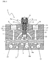
- no. 10 indicates a multiple hydraulic distributor comprising a plurality of hydraulic sections 1 for load sensing applications. At least one of the hydraulic sections 1 is a priority section, while the other hydraulic sections 1 are flow-sharing sections.
- each hydraulic section 1 comprises a main spool 2 longitudinally displaceable within said section 1 in order to selectively transmit pressurised hydraulic fluid coming from a feed line Pal from a pump 100 to workports A,B through a metering orifice 3.
- the main spool 2 is of the six-way three-position type. It is anyway possible to create other configurations, for example four-position, where the additional position, called floating, connects both workports A, B to discharge.
- the main spool 2 is fed by a channel which coincides with the feed line Pal from the pump 100.
- a first chamber 7 is interposed between the main spool 2 and a first end 16a of compensation means 16.
- a second chamber 6 is situated at a second end 16b, opposite the first end 16a, of said compensation means 16.
- the said second chamber 6 is connectable to the feed line Pal by means of a predefined channel Pp in such a way that the hydraulic section 1 operates as a priority section ( figures 1 and 2 ), and else it is connectable to a line LS for detecting the highest load pressure so that said hydraulic section 1 operates as a flow-sharing section ( figures 3 and 4 ).
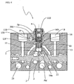
- the compensation means 16 comprise a pressure compensator 40 housed in a bore 9 formed within the hydraulic section 1.
- a plug 110 is provided which, interfacing with the walls of the bore 9 into which it is inserted, forms the second chamber 6.
- figure 3 illustrates a first embodiment (called "without check function") of the flow-sharing hydraulic section 1.
- a spring 80 is preferably housed in the second chamber 6 to elastically couple the compensator 40 and the plug 110.
- the predefined channel Pp though crossing the flow-sharing hydraulic section 1, remains unused because it is isolated by a portion of the plug 110. In this way, communication is excluded between this predefined channel Pp and the second chamber 6.
- Figure 4 illustrates a second embodiment (called “with check function") of the flow-sharing hydraulic section 1.
- an intermediate element 200 is interposed which faces said plug 110.
- the pressure compensator 40 and the intermediate element 200 are facing each other in such a way as to form an intermediate chamber 120 in which a spring 150 is housed.
- the compensation means 16 comprise a pressure compensator 4 and a piston 5 disposed in such a way as to be adjacent in an internal proximity zone 17.
- the pressure compensator 4 extends from the internal proximity zone 17 up to the first end 16a.
- the piston 5, extends from the internal proximity zone 17 up to the second end 16b.
- the pressure compensator 4 and the piston 5 are housed in a common bore 9 formed within hydraulic section 1.
- the piston 5 and the pressure compensator 4 are placed side by side so as to form, in the internal proximity zone 17, an intermediate chamber 12 suitable for communicating with the main spool 2 via a passage bridge 13.
- the predefined channel Pp and the line LS for detecting the highest load pressure are isolated from each other, irrespective of the position taken by the piston 5 within the common bore 9.
- the second chamber 6 houses a first spring 8 which is operatively active on the piston 5 in such a way as to move it away from said pressure compensator 4.
- the pressure compensator 4 and the piston 5 are pushed away from each other by a second spring 15, of negligible force, housed in the intermediate chamber 12.
- the presence of the second spring 15 ensures the assumption of a predetermined position by the pair "pressure compensator 4 - piston 5" in the absence of pressure.
- a plug 11 is provided which, interfacing with the piston 5, forms the second chamber 6. In this way, the plug 11 and the piston 5 are elastically coupled together by means of the first spring 8.
- a passage is provided which allows communication between the second chamber 6 and the predefined channel Pp. The piston 5 is therefore subject, over a surface which interfaces with the plug 11, to the pressure of the fluid from the predefined channel Pp.
- the piston 5 is provided with a valve 14 in order to establish selective communication between the line LS for detecting the highest load pressure and the intermediate chamber 12.
- the intermediate chamber 12 is, in its turn, subjected to the pressure of the passage bridge 13.
- the valve 14 is located within an annular interspace 19 formed between the piston 5 and the common bore 9.
- the valve 14 is of the ball type, maintained within the annular interspace 19 by means of an elastic element 21.
- the selective communication between the line LS for detecting the highest load pressure and the intermediate chamber 12 can be created solely by the seal exerted by the elastic element 21 against the annular interspace 19.
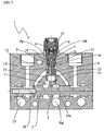
- the main spool 2 is displaceable between a neutral position, in which it does not communicate with the first chamber 7, and an operative position, in which it communicates with said first chamber 7, transmitting to it, through the metering orifice 3, the pressurised hydraulic fluid coming from the feed line Pal.
- the passage bridge 13 does not communicate with the workports A, B.
- the passage bridge 13 is put into communication with one of the workports A, B.
- the valve 14 closes off communication between this line LS for detecting the highest load pressure and the intermediate chamber 12 itself. If, however, the pressure in the line LS for detecting the highest load pressure is lower than the pressure in the intermediate chamber 12, the valve 14 opens communication between this line LS for detecting the highest load pressure and the intermediate chamber 12 itself. In practice, the pressure present at one of the workports A, B is transmitted, via the passage bridge 13 and the intermediate chamber 12, to the line LS for detecting the highest load pressure.
- the pressure compensator 4 is equipped, at its first end 16a, with regulating orifices 22. These regulating orifices 22 are preferably radial holes or notches. The displacements of the pressure compensator 4 within the bore 9 determine a proportional increase or decrease in the passage clearance generated by said regulating orifices 22 between the first chamber 7 and the bridge 13. It follows that, when the main spool 2 is in operative position, the flow delivered to the workports A, B will be substantially constant because it is dependent only on the load generated by the first spring 8.
- a drainage channel 18 is formed in the main spool 2, suitable for effecting selective communication between the passage bridge 13 (and therefore the intermediate chamber 12) and a discharge channel 23 of hydraulic section 1.
- the pressurised fluid coming from the predefined channel Pp pushes the piston 5 closer to the pressure compensator 4 in said internal proximity zone 17, overcoming the resistance of the first spring 8 and the second spring 15 (if present). This ensures a predetermined position for the pressure compensator 4 in the absence of a manoeuvre.
- the main spool 2 is in the operative position, said communication between the discharge channel 23 and the passage bridge 13, through the drainage channel 18, is interrupted.
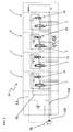
- a hydraulic distributor 10 having a single priority section 1, while all the remaining sections 1 are of the flow-sharing type.
- the predefined channel Pp crosses all hydraulic sections 1, both the priority one and the flow-sharing ones. If the priority section 1 is the one with the greatest load, it will be precisely this one which transmits the regulating signal to a regulating organ 20 of the pump 100 (or alternatively to a three-way compensator of the inlet cover).
- the pressure in the line LS for detecting the highest load pressure (of the priority section 1) is transmitted to the regulating organ 20 of the pump 100 (or to the three-way compensator of the inlet cover) and to the second chamber 6 of all the flow-sharing hydraulic sections.
- the valve 14 in the priority section 1 closes off communication between the line LS for detecting the highest load pressure,and the intermediate chamber 12.
- the compensator 4 of the priority section 1 assumes a position such that the pressure drop between the second chamber 6 and the first chamber 7, and equivalently between the feed line Pal and the first chamber 7, is maintained substantially equal to that corresponding to the load on the first spring 8. It is therefore evident that in the priority section 1, the positions of the compensator 4 and of the piston 5 depend solely on the load on the first spring 8. As a consequence, when the main spool 2 is in the operative position, the flow delivered to the workports A, B is kept substantially constant.
- the proposed hydraulic section proves to be universal, i.e. usable both as a flow-sharing section and as a priority section.
- all the sections (both flow-sharing and priority) of the distributor are crossed by the predefined channel; however this channel is connected to the second chamber in the priority sections, while it is isolated in the flow-sharing sections.
- the design and construction of the proposed hydraulic section are simplified by comparison with the current state of the art because it is sufficient to prepare a single type of section and make different internal connections to pass from flow-sharing operation to priority operation.
- the compensation means are inserted into the appropriate bore, and then the bore itself is closed with the plug.
- the designed check function is integrated into the compensation function, avoiding the need to provide dedicated additional elements (e.g. check valves).
Landscapes
- Engineering & Computer Science (AREA)
- Physics & Mathematics (AREA)
- Fluid Mechanics (AREA)
- Mechanical Engineering (AREA)
- General Engineering & Computer Science (AREA)
- Fluid-Pressure Circuits (AREA)
Claims (17)
- Hydraulikteil (1) zur Verwendung in einem hydraulischen Verteiler (10), umfassend:eine Hauptspule (2), die im Hydraulikteil (1) longitudinal verschiebbar ist, um ein druckbeaufschlagtes Hydraulikfluid, das von einer Speiseleitung (Pal) einer Pumpe (100) kommt, wahlweise an Arbeitsanschlüsse (A, B) durch eine Messblende (3) zu übertragen;Druckausgleichsmittel (16), die der Hauptspule (2) nachgelagert liegen und dazu fähig sind, eine im Wesentlichen konstante Druckminderung durch die Messblende (3) aufrechtzuerhalten;eine erste Kammer (7), die sich zwischen der Hauptspule (2) und einem ersten Ende (16a) der Ausgleichsmittel (16) befindet;eine zweite Kammer (6), die an einem zweiten Ende (16b) gegenüber dem ersten Ende (16a) der Ausgleichsmittel (16) liegt,dadurch gekennzeichnet, dass die zweite Kammer (6) an die Speiseleitung (Pal) mithilfe eines vordefinierten Kanals (Pp) anschließbar ist, sodass der Hydraulikteil (1) als ein vorrangiger Teil betrieben wird, und an eine Leitung (LS) zum Ermitteln des höchsten Ladungsdrucks anschließbar ist, sodass der Hydraulikteil (1) als ein durchflussverteilender Teil betrieben wird.
- Hydraulikteil (1) nach Anspruch 1, wobei der vordefinierte Kanal (Pp) und die Leitung (LS) zum Ermitteln des höchsten Ladungsdrucks voneinander isoliert sind.
- Vorrangiger Hydraulikteil (1) nach Anspruch 1 oder 2, wobei die Ausgleichsmittel (16) einen Druckausgleicher (4) und einen Kolben (5) umfassen, die so angeordnet sind, dass sie benachbart in einem inneren Nahbereich (17) liegen, wobei sich der Ausgleicher (4) vom Innenbereich (17) bis zum ersten Ende (16a) erstreckt und sich der Kolben (5) vom Innenbereich (17) bis zum zweiten Ende (16b) erstreckt.
- Vorrangiger Hydraulikteil (1) nach Anspruch 3, wobei die Hauptspule (2) zwischen einer neutralen Position, in der sie nicht mit der ersten Kammer (7) in Verbindung steht, und einer Betriebsposition, in der sie mit der ersten Kammer (7) in Verbindung steht, sodass durch die Messblende (3) das von der Speiseleitung (Pal) kommende druckbeaufschlagte Hydraulikfluid übertragen wird, verschiebbar ist.
- Vorrangiger Hydraulikteil (1) nach Anspruch 3 oder 4, wobei der Druckausgleicher (4) und der Kolben (5) in einer gemeinsamen Bohrung (9) aufgenommen sind.
- Vorrangiger Hydraulikteil (1) nach Anspruch 5, wobei der Kolben (5) und der Druckausgleicher (4) nebeneinander platziert sind, sodass im inneren Nahbereich (17) eine Zwischenkammer (12) definiert wird, die dazu geeignet ist, mit der Hauptspule (2) über eine Übergangsbrücke (13) in Verbindung zu stehen.
- Vorrangiger Hydraulikteil (1) nach Anspruch 6, wobei die Übergangsbrücke (13), wenn die Hauptspule (2) in der neutralen Position ist, nicht mit den Arbeitsanschlüssen (A, B) in Verbindung steht, während die Übergangsbrücke (13), wenn die Hauptspule (2) in der Betriebsposition ist, mit den Arbeitsanschlüssen (A, B) in Verbindung steht.
- Vorrangiger Hydraulikteil (1) nach Anspruch 6 oder 7, ferner umfassend eine erste Feder (8), die in der zweiten Kammer (6) aufgenommen ist und betriebsbereit auf den Kolben (5) einwirkt, sodass er vom Druckausgleicher (4) wegbewegt wird.
- Vorrangiger Hydraulikteil (1) nach Anspruch 8, ferner umfassend einen Stopfen (11), der dazu dient, die gemeinsame Bohrung (9) zu schließen, wobei der Stopfen (11) mit dem Kolben (5) so zusammenschaltet, dass die zweite Kammer (6) definiert wird, sodass der Stopfen (11) und der Kolben (5) mithilfe der ersten Feder (8) elastisch aneinandergekoppelt sind.
- Vorrangiger Hydraulikteil (1) nach Anspruch 8 oder 9, wobei der Kolben (5) mit einem Ventil (14) ausgestattet ist, um eine wahlweise Verbindung zwischen der Leitung (LS) zum Ermitteln des höchsten Ladungsdrucks und der Zwischenkammer (12) herzustellen.
- Vorrangiger Hydraulikteil (1) nach Anspruch 10, wobei das Ventil (14) die Verbindung zwischen der Leitung (LS) zum Ermitteln des höchsten Ladungsdrucks und der Zwischenkammer (12) unterbricht, wenn der Druck in der Leitung (LS) zum Ermitteln des höchsten Ladungsdrucks größer als der Druck in der Zwischenkammer (12) ist, während das Ventil (14) die Verbindung zwischen der Leitung (LS) zum Ermitteln des höchsten Ladungsdrucks und der Zwischenkammer (12) öffnet, wenn der Druck in der Leitung (LS) zum Ermitteln des höchsten Ladungsdrucks niedriger als der Druck in der Zwischenkammer (12) ist.
- Vorrangiger Hydraulikteil (1) nach den Ansprüchen 8 bis 11, wobei der Druckausgleicher (4) und der Kolben (5) durch eine zweite Feder (15) einer vernachlässigbaren Kraft, die in der Zwischenkammer (12) aufgenommen ist, auseinander geschoben werden.
- Vorrangiger Hydraulikteil (1) nach Anspruch 11, wobei, wenn die Hauptspule (2) in der neutralen Position ist und die Übergangsbrücke (13) mit einem Ausflusskanal (23) des Hydraulikteils (1) durch einen in der Hauptspule (2) ausgebildeten Ablaufkanal (18) in Verbindung steht, das vom vordefinierten Kanal (Pp) kommende druckbeaufschlagte Fluid den Kolben (5) näher zum Druckausgleicher (4) im inneren Nahbereich (17) schiebt, wobei der Widerstand der ersten Feder (8) überwunden wird.
- Vorrangiger Hydraulikteil (1) nach Anspruch 12, wobei, wenn die Hauptspule (2) in der neutralen Position ist und die Übergangsbrücke (13) mit einem Ausflusskanal (23) des Hydraulikteils (1) durch einen in der Hauptspule (2) ausgebildeten Ablaufkanal (18) in Verbindung steht, das vom vordefinierten Kanal (Pp) kommende druckbeaufschlagte Fluid den Kolben (5) näher zum Druckausgleicher (4) im inneren Nahbereich (17) schiebt, wobei der Widerstand der ersten Feder (8) und der zweiten Feder (15) überwunden wird.
- Vorrangiger Hydraulikteil (1) nach den Ansprüchen 10 bis 14, wobei, wenn die Hauptspule (2) in der Betriebsposition ist und das Ventil (14) offen ist, der Druck des von der Speiseleitung (Pal) kommenden Hydraulikfluids zunimmt, bis die Summe des Drucks, der in der ersten Kammer (7) ausgeübt wird, und des äquivalenten Drucks der ersten Feder (8) dem Wert des Drucks im vordefinierten Kanal (Pp) entspricht, sodass der Druckausgleicher (4) in Richtung des Kolbens (5) geschoben wird, wodurch die Öffnung der Verbindung zwischen der ersten Kammer (7) und der Übergangsbrücke (13) ermöglicht wird.
- Vorrangiger Hydraulikteil (1) nach den Ansprüchen 10 bis 14, wobei, wenn die Hauptspule (2) in der Betriebsposition ist, wenn der Druck des Hydraulikfluids in der Übergangsbrücke (13) höher als der Druck des von der Speiseleitung (Pal) kommenden Hydraulikfluids ist, und damit des in der ersten Kammer (7) und in der zweiten Kammer (6) wirkenden Drucks, der Kolben (5) in Kontakt mit dem Stopfen (11) gehalten wird, der Druckausgleicher (4) vom Kolben (5) wegbewegt wird, sodass die Verbindung zwischen der ersten Kammer (7) und der Übergangsbrücke (13) unterbrochen wird und sich das Ventil (14) öffnet, während, wenn der Druck des von der Speiseleitung (Pal) kommenden Hydraulikfluids höher als der Druck des Hydraulikfluids in der Übergangsbrücke (13) ist, der Kolben (5) und der Druckausgleicher (4) in gegenseitigen Kontakt im inneren Nahbereich (17) geschoben werden und der Druckausgleicher (4) die Verbindung zwischen der ersten Kammer (7) und der Übergangsbrücke (13) öffnet, wodurch er eine Position einnimmt, die vom Gleichgewicht zwischen dem Druck der Leitung des vordefinierten Kanals (Pp) und der Summe des in der ersten Kammer (7) ausgeübten Drucks und des äquivalenten Drucks der ersten Feder (8) abhängt.
- Hydraulischer Verteiler (10), umfassend eine Vielzahl von Hydraulikteilen (1) nach Anspruch 1 oder 2, wobei mindestens einer der Hydraulikteile (1) ein vorrangiger Teil ist, wobei der vordefinierte Kanal (Pp) durch alle Hydraulikteile (1) des hydraulischen Verteilers (10) verläuft, jedoch nur mit der zweiten Kammer (6) des mindestens einen vorrangigen Hydraulikteils (1) in Verbindung steht.
Applications Claiming Priority (1)
| Application Number | Priority Date | Filing Date | Title |
|---|---|---|---|
| PCT/IT2010/000033 WO2011096001A1 (en) | 2010-02-02 | 2010-02-02 | Hydraulic section for load sensing applications and multiple hydraulic distributor |
Publications (2)
| Publication Number | Publication Date |
|---|---|
| EP2531735A1 EP2531735A1 (de) | 2012-12-12 |
| EP2531735B1 true EP2531735B1 (de) | 2013-12-11 |
Family
ID=42829038
Family Applications (1)
| Application Number | Title | Priority Date | Filing Date |
|---|---|---|---|
| EP10707685.3A Active EP2531735B1 (de) | 2010-02-02 | 2010-02-02 | Hydraulikteil für lastmessungsanwendungen und hydraulischer mehrfachverteiler |
Country Status (3)
| Country | Link |
|---|---|
| US (1) | US8646338B2 (de) |
| EP (1) | EP2531735B1 (de) |
| WO (1) | WO2011096001A1 (de) |
Families Citing this family (4)
| Publication number | Priority date | Publication date | Assignee | Title |
|---|---|---|---|---|
| EP3034705A4 (de) * | 2013-08-13 | 2017-04-05 | Volvo Construction Equipment AB | Durchflussregelventil für eine baumaschine |
| EP2918853B1 (de) | 2014-03-11 | 2016-03-09 | Bucher Hydraulics S.p.A. | Hydraulikteil für Lastmessungsanwendungen und hydraulischer Mehrfachverteiler |
| EP2980416B1 (de) | 2014-07-31 | 2019-06-05 | Bucher Hydraulics S.p.A. | Hydraulikteil für Lastmessungsanwendungen und hydraulischer Mehrfachverteiler |
| US12442396B2 (en) * | 2020-01-27 | 2025-10-14 | Parker-Hannifin Corporation | Valve with an adjustable flow sharing pressure compensator |
Family Cites Families (12)
| Publication number | Priority date | Publication date | Assignee | Title |
|---|---|---|---|---|
| US4574839A (en) * | 1984-04-19 | 1986-03-11 | J. I. Case Company | Directional control valve with integral flow control valve |
| DE4005967C2 (de) | 1990-02-26 | 1996-05-09 | Rexroth Mannesmann Gmbh | Steueranordnung für mehrere hydraulische Verbraucher |
| JPH0758082B2 (ja) * | 1990-06-22 | 1995-06-21 | 株式会社ゼクセル | 油圧制御弁装置 |
| DE4235707B4 (de) | 1992-10-22 | 2007-10-18 | Linde Material Handling Gmbh | Hydrostatisches Antriebssystem |
| DE19703997A1 (de) | 1997-02-04 | 1998-08-06 | Mannesmann Rexroth Ag | Hydraulischer Steuerkreis für einen vorrangigen und für einen nachrangigen hydraulischen Verbraucher |
| US5890362A (en) * | 1997-10-23 | 1999-04-06 | Husco International, Inc. | Hydraulic control valve system with non-shuttle pressure compensator |
| DE19828963A1 (de) * | 1998-06-29 | 1999-12-30 | Mannesmann Rexroth Ag | Hydraulische Schaltung |
| US6098403A (en) * | 1999-03-17 | 2000-08-08 | Husco International, Inc. | Hydraulic control valve system with pressure compensator |
| DE10325295A1 (de) * | 2003-06-04 | 2004-12-23 | Bosch Rexroth Ag | Hydraulische Steueranordnung |
| DE10325296A1 (de) * | 2003-06-04 | 2004-12-23 | Bosch Rexroth Ag | Hydraulische Steueranordnung |
| US7146808B2 (en) * | 2004-10-29 | 2006-12-12 | Caterpillar Inc | Hydraulic system having priority based flow control |
| ATE519949T1 (de) | 2007-06-26 | 2011-08-15 | Walvoil Spa | Lasterfassungswegeventil mit einem unter sättigungsbedingungen priorität habenden element |
-
2010
- 2010-02-02 EP EP10707685.3A patent/EP2531735B1/de active Active
- 2010-02-02 US US13/058,147 patent/US8646338B2/en active Active
- 2010-02-02 WO PCT/IT2010/000033 patent/WO2011096001A1/en not_active Ceased
Also Published As
| Publication number | Publication date |
|---|---|
| EP2531735A1 (de) | 2012-12-12 |
| US20120144926A1 (en) | 2012-06-14 |
| WO2011096001A1 (en) | 2011-08-11 |
| US8646338B2 (en) | 2014-02-11 |
Similar Documents
| Publication | Publication Date | Title |
|---|---|---|
| US7487707B2 (en) | Hydraulic valve assembly with a pressure compensated directional spool valve and a regeneration shunt valve | |
| EP3078571B1 (de) | Hydraulisches lenksystem | |
| US8464757B2 (en) | Hydraulic valve device | |
| GB2419195A (en) | Hydraulic valve arrangement for assisting regenerative working | |
| JPH11210705A (ja) | 非シャトル圧力補償器付液圧制御バルブ装置 | |
| EP2531735B1 (de) | Hydraulikteil für lastmessungsanwendungen und hydraulischer mehrfachverteiler | |
| JPH11247802A (ja) | 負荷検出優先度を有する液圧制御バルブシステム | |
| CN101155722A (zh) | 电液转向控制系统 | |
| KR20160015154A (ko) | 건설 기계 | |
| US20160032566A1 (en) | Hydraulic section for load sensing applications and multiple hydraulic distributor | |
| EP1143151B1 (de) | Rohrbruch steuerventil vorrichtung | |
| US6212886B1 (en) | Hydraulic drive system and directional control valve apparatus in hydraulic machine | |
| EP3312436B1 (de) | Anti-rohrbruch apparatus | |
| EP1726723B1 (de) | Arbeitsmaschine | |
| KR102716420B1 (ko) | 농기계의 자동 조향 장치용 유압밸브장치 | |
| JP6038509B2 (ja) | 圧力補償弁とこの圧力補償弁と一体化した油圧制御弁並びに油圧制御弁を搭載した建設機械 | |
| EP3191716B1 (de) | Steuerungsvorrichtung für leckfreie wegeventile | |
| US10947996B2 (en) | Systems and methods for selective enablement of hydraulic operation | |
| JP4851318B2 (ja) | 制御装置および圧力補償弁 | |
| CA2915009A1 (en) | Flow rate control valve for construction machine | |
| EP2446152B1 (de) | Hydraulikhauptventil und hilfsventil | |
| JP2000283109A (ja) | アクチュエータ制御装置 | |
| JP3730739B2 (ja) | 負荷補償付き方向切換弁装置 | |
| EP2918853B1 (de) | Hydraulikteil für Lastmessungsanwendungen und hydraulischer Mehrfachverteiler | |
| US20110308642A1 (en) | Hydraulic valve device |
Legal Events
| Date | Code | Title | Description |
|---|---|---|---|
| PUAI | Public reference made under article 153(3) epc to a published international application that has entered the european phase |
Free format text: ORIGINAL CODE: 0009012 |
|
| 17P | Request for examination filed |
Effective date: 20110202 |
|
| AK | Designated contracting states |
Kind code of ref document: A1 Designated state(s): AT BE BG CH CY CZ DE DK EE ES FI FR GB GR HR HU IE IS IT LI LT LU LV MC MK MT NL NO PL PT RO SE SI SK SM TR |
|
| DAX | Request for extension of the european patent (deleted) | ||
| GRAP | Despatch of communication of intention to grant a patent |
Free format text: ORIGINAL CODE: EPIDOSNIGR1 |
|
| INTG | Intention to grant announced |
Effective date: 20130930 |
|
| GRAS | Grant fee paid |
Free format text: ORIGINAL CODE: EPIDOSNIGR3 |
|
| GRAA | (expected) grant |
Free format text: ORIGINAL CODE: 0009210 |
|
| AK | Designated contracting states |
Kind code of ref document: B1 Designated state(s): AT BE BG CH CY CZ DE DK EE ES FI FR GB GR HR HU IE IS IT LI LT LU LV MC MK MT NL NO PL PT RO SE SI SK SM TR |
|
| REG | Reference to a national code |
Ref country code: GB Ref legal event code: FG4D |
|
| REG | Reference to a national code |
Ref country code: CH Ref legal event code: EP |
|
| REG | Reference to a national code |
Ref country code: AT Ref legal event code: REF Ref document number: 644761 Country of ref document: AT Kind code of ref document: T Effective date: 20140115 |
|
| REG | Reference to a national code |
Ref country code: IE Ref legal event code: FG4D |
|
| REG | Reference to a national code |
Ref country code: DE Ref legal event code: R096 Ref document number: 602010012338 Country of ref document: DE Effective date: 20140206 |
|
| REG | Reference to a national code |
Ref country code: SE Ref legal event code: TRGR |
|
| REG | Reference to a national code |
Ref country code: NL Ref legal event code: VDEP Effective date: 20131211 |
|
| REG | Reference to a national code |
Ref country code: AT Ref legal event code: MK05 Ref document number: 644761 Country of ref document: AT Kind code of ref document: T Effective date: 20131211 |
|
| PG25 | Lapsed in a contracting state [announced via postgrant information from national office to epo] |
Ref country code: NL Free format text: LAPSE BECAUSE OF FAILURE TO SUBMIT A TRANSLATION OF THE DESCRIPTION OR TO PAY THE FEE WITHIN THE PRESCRIBED TIME-LIMIT Effective date: 20131211 Ref country code: HR Free format text: LAPSE BECAUSE OF FAILURE TO SUBMIT A TRANSLATION OF THE DESCRIPTION OR TO PAY THE FEE WITHIN THE PRESCRIBED TIME-LIMIT Effective date: 20131211 Ref country code: FI Free format text: LAPSE BECAUSE OF FAILURE TO SUBMIT A TRANSLATION OF THE DESCRIPTION OR TO PAY THE FEE WITHIN THE PRESCRIBED TIME-LIMIT Effective date: 20131211 Ref country code: NO Free format text: LAPSE BECAUSE OF FAILURE TO SUBMIT A TRANSLATION OF THE DESCRIPTION OR TO PAY THE FEE WITHIN THE PRESCRIBED TIME-LIMIT Effective date: 20140311 Ref country code: LT Free format text: LAPSE BECAUSE OF FAILURE TO SUBMIT A TRANSLATION OF THE DESCRIPTION OR TO PAY THE FEE WITHIN THE PRESCRIBED TIME-LIMIT Effective date: 20131211 |
|
| REG | Reference to a national code |
Ref country code: LT Ref legal event code: MG4D |
|
| PG25 | Lapsed in a contracting state [announced via postgrant information from national office to epo] |
Ref country code: CY Free format text: LAPSE BECAUSE OF FAILURE TO SUBMIT A TRANSLATION OF THE DESCRIPTION OR TO PAY THE FEE WITHIN THE PRESCRIBED TIME-LIMIT Effective date: 20131211 Ref country code: AT Free format text: LAPSE BECAUSE OF FAILURE TO SUBMIT A TRANSLATION OF THE DESCRIPTION OR TO PAY THE FEE WITHIN THE PRESCRIBED TIME-LIMIT Effective date: 20131211 Ref country code: LV Free format text: LAPSE BECAUSE OF FAILURE TO SUBMIT A TRANSLATION OF THE DESCRIPTION OR TO PAY THE FEE WITHIN THE PRESCRIBED TIME-LIMIT Effective date: 20131211 |
|
| PG25 | Lapsed in a contracting state [announced via postgrant information from national office to epo] |
Ref country code: IS Free format text: LAPSE BECAUSE OF FAILURE TO SUBMIT A TRANSLATION OF THE DESCRIPTION OR TO PAY THE FEE WITHIN THE PRESCRIBED TIME-LIMIT Effective date: 20140411 Ref country code: BE Free format text: LAPSE BECAUSE OF FAILURE TO SUBMIT A TRANSLATION OF THE DESCRIPTION OR TO PAY THE FEE WITHIN THE PRESCRIBED TIME-LIMIT Effective date: 20131211 Ref country code: EE Free format text: LAPSE BECAUSE OF FAILURE TO SUBMIT A TRANSLATION OF THE DESCRIPTION OR TO PAY THE FEE WITHIN THE PRESCRIBED TIME-LIMIT Effective date: 20131211 |
|
| PG25 | Lapsed in a contracting state [announced via postgrant information from national office to epo] |
Ref country code: PT Free format text: LAPSE BECAUSE OF FAILURE TO SUBMIT A TRANSLATION OF THE DESCRIPTION OR TO PAY THE FEE WITHIN THE PRESCRIBED TIME-LIMIT Effective date: 20140411 Ref country code: ES Free format text: LAPSE BECAUSE OF FAILURE TO SUBMIT A TRANSLATION OF THE DESCRIPTION OR TO PAY THE FEE WITHIN THE PRESCRIBED TIME-LIMIT Effective date: 20131211 Ref country code: PL Free format text: LAPSE BECAUSE OF FAILURE TO SUBMIT A TRANSLATION OF THE DESCRIPTION OR TO PAY THE FEE WITHIN THE PRESCRIBED TIME-LIMIT Effective date: 20131211 Ref country code: SK Free format text: LAPSE BECAUSE OF FAILURE TO SUBMIT A TRANSLATION OF THE DESCRIPTION OR TO PAY THE FEE WITHIN THE PRESCRIBED TIME-LIMIT Effective date: 20131211 Ref country code: RO Free format text: LAPSE BECAUSE OF FAILURE TO SUBMIT A TRANSLATION OF THE DESCRIPTION OR TO PAY THE FEE WITHIN THE PRESCRIBED TIME-LIMIT Effective date: 20131211 Ref country code: CZ Free format text: LAPSE BECAUSE OF FAILURE TO SUBMIT A TRANSLATION OF THE DESCRIPTION OR TO PAY THE FEE WITHIN THE PRESCRIBED TIME-LIMIT Effective date: 20131211 |
|
| REG | Reference to a national code |
Ref country code: DE Ref legal event code: R097 Ref document number: 602010012338 Country of ref document: DE |
|
| PG25 | Lapsed in a contracting state [announced via postgrant information from national office to epo] |
Ref country code: LU Free format text: LAPSE BECAUSE OF FAILURE TO SUBMIT A TRANSLATION OF THE DESCRIPTION OR TO PAY THE FEE WITHIN THE PRESCRIBED TIME-LIMIT Effective date: 20140202 Ref country code: MC Free format text: LAPSE BECAUSE OF FAILURE TO SUBMIT A TRANSLATION OF THE DESCRIPTION OR TO PAY THE FEE WITHIN THE PRESCRIBED TIME-LIMIT Effective date: 20131211 |
|
| REG | Reference to a national code |
Ref country code: CH Ref legal event code: PL |
|
| PLBE | No opposition filed within time limit |
Free format text: ORIGINAL CODE: 0009261 |
|
| STAA | Information on the status of an ep patent application or granted ep patent |
Free format text: STATUS: NO OPPOSITION FILED WITHIN TIME LIMIT |
|
| PG25 | Lapsed in a contracting state [announced via postgrant information from national office to epo] |
Ref country code: CH Free format text: LAPSE BECAUSE OF NON-PAYMENT OF DUE FEES Effective date: 20140228 Ref country code: LI Free format text: LAPSE BECAUSE OF NON-PAYMENT OF DUE FEES Effective date: 20140228 Ref country code: DK Free format text: LAPSE BECAUSE OF FAILURE TO SUBMIT A TRANSLATION OF THE DESCRIPTION OR TO PAY THE FEE WITHIN THE PRESCRIBED TIME-LIMIT Effective date: 20131211 |
|
| 26N | No opposition filed |
Effective date: 20140912 |
|
| REG | Reference to a national code |
Ref country code: IE Ref legal event code: MM4A |
|
| REG | Reference to a national code |
Ref country code: DE Ref legal event code: R097 Ref document number: 602010012338 Country of ref document: DE Effective date: 20140912 |
|
| PG25 | Lapsed in a contracting state [announced via postgrant information from national office to epo] |
Ref country code: IE Free format text: LAPSE BECAUSE OF NON-PAYMENT OF DUE FEES Effective date: 20140202 |
|
| PG25 | Lapsed in a contracting state [announced via postgrant information from national office to epo] |
Ref country code: SI Free format text: LAPSE BECAUSE OF FAILURE TO SUBMIT A TRANSLATION OF THE DESCRIPTION OR TO PAY THE FEE WITHIN THE PRESCRIBED TIME-LIMIT Effective date: 20131211 |
|
| PG25 | Lapsed in a contracting state [announced via postgrant information from national office to epo] |
Ref country code: MT Free format text: LAPSE BECAUSE OF FAILURE TO SUBMIT A TRANSLATION OF THE DESCRIPTION OR TO PAY THE FEE WITHIN THE PRESCRIBED TIME-LIMIT Effective date: 20131211 |
|
| REG | Reference to a national code |
Ref country code: FR Ref legal event code: PLFP Year of fee payment: 7 |
|
| PG25 | Lapsed in a contracting state [announced via postgrant information from national office to epo] |
Ref country code: SM Free format text: LAPSE BECAUSE OF FAILURE TO SUBMIT A TRANSLATION OF THE DESCRIPTION OR TO PAY THE FEE WITHIN THE PRESCRIBED TIME-LIMIT Effective date: 20131211 |
|
| PG25 | Lapsed in a contracting state [announced via postgrant information from national office to epo] |
Ref country code: GR Free format text: LAPSE BECAUSE OF FAILURE TO SUBMIT A TRANSLATION OF THE DESCRIPTION OR TO PAY THE FEE WITHIN THE PRESCRIBED TIME-LIMIT Effective date: 20140312 Ref country code: BG Free format text: LAPSE BECAUSE OF FAILURE TO SUBMIT A TRANSLATION OF THE DESCRIPTION OR TO PAY THE FEE WITHIN THE PRESCRIBED TIME-LIMIT Effective date: 20131211 |
|
| PG25 | Lapsed in a contracting state [announced via postgrant information from national office to epo] |
Ref country code: HU Free format text: LAPSE BECAUSE OF FAILURE TO SUBMIT A TRANSLATION OF THE DESCRIPTION OR TO PAY THE FEE WITHIN THE PRESCRIBED TIME-LIMIT; INVALID AB INITIO Effective date: 20100202 |
|
| REG | Reference to a national code |
Ref country code: FR Ref legal event code: PLFP Year of fee payment: 8 |
|
| REG | Reference to a national code |
Ref country code: FR Ref legal event code: PLFP Year of fee payment: 9 |
|
| PG25 | Lapsed in a contracting state [announced via postgrant information from national office to epo] |
Ref country code: MK Free format text: LAPSE BECAUSE OF FAILURE TO SUBMIT A TRANSLATION OF THE DESCRIPTION OR TO PAY THE FEE WITHIN THE PRESCRIBED TIME-LIMIT Effective date: 20131211 |
|
| PGFP | Annual fee paid to national office [announced via postgrant information from national office to epo] |
Ref country code: SE Payment date: 20200221 Year of fee payment: 11 |
|
| PGFP | Annual fee paid to national office [announced via postgrant information from national office to epo] |
Ref country code: TR Payment date: 20200130 Year of fee payment: 11 |
|
| REG | Reference to a national code |
Ref country code: SE Ref legal event code: EUG |
|
| PG25 | Lapsed in a contracting state [announced via postgrant information from national office to epo] |
Ref country code: SE Free format text: LAPSE BECAUSE OF NON-PAYMENT OF DUE FEES Effective date: 20210203 |
|
| PG25 | Lapsed in a contracting state [announced via postgrant information from national office to epo] |
Ref country code: TR Free format text: LAPSE BECAUSE OF NON-PAYMENT OF DUE FEES Effective date: 20210202 |
|
| P01 | Opt-out of the competence of the unified patent court (upc) registered |
Effective date: 20230526 |
|
| PGFP | Annual fee paid to national office [announced via postgrant information from national office to epo] |
Ref country code: DE Payment date: 20250226 Year of fee payment: 16 |
|
| PGFP | Annual fee paid to national office [announced via postgrant information from national office to epo] |
Ref country code: FR Payment date: 20250224 Year of fee payment: 16 |
|
| PGFP | Annual fee paid to national office [announced via postgrant information from national office to epo] |
Ref country code: IT Payment date: 20250227 Year of fee payment: 16 Ref country code: GB Payment date: 20250218 Year of fee payment: 16 |