EP2531002B1 - Cooking device - Google Patents
Cooking device Download PDFInfo
- Publication number
- EP2531002B1 EP2531002B1 EP11736816.7A EP11736816A EP2531002B1 EP 2531002 B1 EP2531002 B1 EP 2531002B1 EP 11736816 A EP11736816 A EP 11736816A EP 2531002 B1 EP2531002 B1 EP 2531002B1
- Authority
- EP
- European Patent Office
- Prior art keywords
- boiling
- over
- detection part
- over detection
- top plate
- Prior art date
- Legal status (The legal status is an assumption and is not a legal conclusion. Google has not performed a legal analysis and makes no representation as to the accuracy of the status listed.)
- Active
Links
Images


Classifications
-
- H—ELECTRICITY
- H05—ELECTRIC TECHNIQUES NOT OTHERWISE PROVIDED FOR
- H05B—ELECTRIC HEATING; ELECTRIC LIGHT SOURCES NOT OTHERWISE PROVIDED FOR; CIRCUIT ARRANGEMENTS FOR ELECTRIC LIGHT SOURCES, IN GENERAL
- H05B6/00—Heating by electric, magnetic or electromagnetic fields
- H05B6/02—Induction heating
- H05B6/06—Control, e.g. of temperature, of power
- H05B6/062—Control, e.g. of temperature, of power for cooking plates or the like
-
- F—MECHANICAL ENGINEERING; LIGHTING; HEATING; WEAPONS; BLASTING
- F24—HEATING; RANGES; VENTILATING
- F24C—DOMESTIC STOVES OR RANGES ; DETAILS OF DOMESTIC STOVES OR RANGES, OF GENERAL APPLICATION
- F24C15/00—Details
- F24C15/10—Tops, e.g. hot plates; Rings
- F24C15/102—Tops, e.g. hot plates; Rings electrically heated
Definitions
- the present invention relates to a cooking device having a top plate on which a container with liquid contained therein is to be placed.
- a circular- or polygonal-shaped electrode that surrounds a portion of the top plate for container placement (i.e., a portion positioned above a heating device for heating the container) is provided to detect liquid boiled over from the container, e.g. a pan, on the top plate (see PTL1).
- JP 2005-257202 A relates to a cooking stove.
- the cooking stove is provided with a heating part for heating a heated object from beneath, a detecting part for detecting the boiling-over from the heated object arranged so as to surround the heating part, and a determining means for determining occurrence of the boiling-over by the detecting part.
- a cooking device for heating a container comprising:
- connection part is set narrower in width than the boiling-over detection part and the contact part.
- the boiling-over detection part includes a rear-side boiling-over detection part placed on a more rear side of the cooking device and a front-side boiling-over detection part placed on a more front side of the cooking device than the rear-side boiling-over detection part, so as to surround the portion of the top plate positioned above the heating device, and the connection part electrically connected to one end of the rear-side boiling-over detection part runs through on the outer peripheral side of the front-side boiling-over detection part.
- the resistance value of the electrode can be inspected easily by using the contact part electrically connected to one end of the boiling-over detection part via the connection part as well as the other end of the boiling-over detection part. Therefore, it becomes implementable to produce a plurality of cooking devices generally equal in electrode resistance value thereamong.
- the contact part and the connection part are farther from the heating device than the boiling-over detection part. Therefore, upon occurrence of boiling-over of the liquid from the container above the heating device, the contact part and the connection part do not largely change in capacitance as compared with the boiling-over detection part. For this reason, the liquid boiled over to a portion of the top plate positioned above the boiling-over detection part can be detected with high accuracy.
- produced plural cooking devices are enabled to detect boiling-over of the liquid with high accuracy and with generally equal accuracy thereamong.
- a first invention provides a cooking device for heating a container that comprising: a ceramic top plate on which the container is to be placed; a heating device provided below the top plate and serving for heating the container; a conductor electrode provided in a lower face of the top plate and including a belt-like boiling-over detection part placed near an outer periphery of a portion of the top plate positioned above the heating device, a contact part for supplying an AC current to the boiling-over detection part, and a connection part for electrically connecting the contact part and one end of the boiling-over detection part to each other; a capacitance detection device for supplying an AC voltage to the boiling-over detection part via the contact part to detect an increase or decrease in capacitance of the boiling-over detection part; and a control device for, upon detection of boiling-over of liquid from the container based on a change in capacitance detected by the capacitance detection device, decreasing electric power supplied to the heating device or stopping power supply, wherein the contact part of the electrode is provided at a position farther from the heating device and on
- the resistance value of the electrode can be inspected easily by using the contact part electrically connected to one end of the boiling-over detection part via the connection part as well as the other end of the boiling-over detection part. Therefore, it becomes implementable to produce a plurality of cooking devices generally equal in electrode resistance value thereamong.
- the contact part and the connection part are farther from the heating device than the boiling-over detection part. Therefore, upon occurrence of boiling-over of the liquid from the container above the heating device, the contact part and the connection part do not largely change in capacitance as compared with the boiling-over detection part. For this reason, the liquid boiled over to a portion of the top plate positioned above the boiling-over detection part can be detected with high accuracy.
- produced plural cooking devices are enabled to detect boiled-over liquid with high accuracy and with generally equal accuracy thereamong.
- the cooking device of the first invention is configured so that the connection part is set narrower in width than the boiling-over detection part and the contact part.
- connection part is set narrower in width than the boiling-over detection part, the boiling-over detection part more subserviently changes in capacitance, as compared with the connection part. Therefore, the liquid boiled over to the portion of the top plate positioned above the boiling-over detection part can be detected with even higher accuracy.
- the cooking device of the first or second invention is configured so that the boiling-over detection part includes a rear-side boiling-over detection part placed on a more rear side of the cooking device and a front-side boiling-over detection part placed on a more front side of the cooking device than the rear-side boiling-over detection part, so as to surround the portion of the top plate positioned above the heating device, and the connection part electrically connected to one end of the rear-side boiling-over detection part runs through on the outer peripheral side of the front-side boiling-over detection part.
- connection part connected to the rear-side boiling-over detection part runs through on the outer peripheral side of the front-side boiling-over detection part, boiled-over liquid passes through above the front-side boiling-over detection part before reaching above the connection part. Then, the heating device is decreased in its heating output or stopped based on a change in capacitance of the front-side boiling-over detection part. Therefore, the boiled-over liquid is less likely to reach above the connection part, so that the connection part does not largely change in capacitance. Thus, it becomes implementable to detect boiled-over liquid based on a change in capacitance of the front-side or rear-side boiling-over detection part.
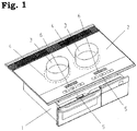
- Fig. 1 is a perspective view of a cooking device according to this embodiment.
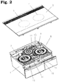
- Fig. 2 is a perspective view showing a state in which the top plate is separated off in the cooking device according to this embodiment.
- Fig. 3 is a perspective view showing a state in which the top plate is excluded in the cooking device according to this embodiment,
- Fig. 4 is a view showing a lower face of the top plate in the cooking device according to this embodiment.
- Fig. 5 is a sectional view showing a state in which the liquid is boiled over from the container on the cooking device according to this embodiment.
- the cooking device has a body casing 1 having an opening in its upper part, and a ceramic top plate 2 covering the opening of the body casing 1.
- a heating position display part 4 for showing a position in which a pan or other container 3 is to be placed is provided in an upper face of the top plate 2.
- an operation display part 5 for starting or stopping heating and a heating state display part 6 for displaying a heating state or the like are provided on the front side of the cooking device with respect to the heating position display part 4.
- heating coils or other heating devices 7, 8 are provided below the heating position display part 4 of the top plate 2, and a control device 9 for controlling heating outputs of the heating devices 7, 8 is placed below the heating devices 7, 8.
- the housing forming the outer profile of the body casing 1 is connected to the ground via a power cable.
- a display board 10 for showing a heating output or heating state is placed on the front side of the cooking device with respect to the heating devices 7, 8.
- the display board 10 is connected to the control device 9.
- the display board 10 has LEDs, LCDs or the like that emit light based on a heating state. Light emission by these LEDs or LCDs makes it possible for the heating state display part 6 of the top plate 2 to display a heating state.
- the display board 10 also includes an operation-use capacitance detection device 11, and the operation-use capacitance detection device 11 is connected to an operation-use connecting terminal 12.
- the operation-use capacitance detection device 11 supplies an AC voltage to the operation-use connecting terminal 12 to detect an increase or decrease in the capacitance of an operation-use electrode 27 connected to the operation-use connecting terminal 12.
- the display board 10 further includes an electrode-use capacitance detection device 13, the electrode-use capacitance detection device 13 is connected to an electrode-use connecting terminal 14.
- the electrode-use capacitance detection device 13 supplies an AC voltage to later-described electrodes 15, 16 via the electrode-use connecting terminal 14 to detect an increase or decrease in capacitance of the electrodes 15, 16.
- the electrode-use capacitance detection device 13 further transmits a signal based on a capacitance detection result to the control device 9.
- the electrodes 15, 16 are provided in a lower face of the top plate 2.
- the electrodes 15, 16 are formed by printing carbon on the lower face of the top plate 2.
- electrodes 15, 16 of preformed thin copper plates may also be bonded to the lower face of the top plate 2.
- the electrode 15 includes: a belt-like boiling-over detection part 18 which is placed near an outer periphery of a portion of the lower face of the top plate 2 shown by an area 17, the portion being positioned above the heating device 7 so as to face the heating device 7 and being generally identical in shape to an upper face of the heating device 7, and which is formed into a generally arc shape extending along the outer periphery of the area 17; an inspection point part 19 provided at one end of the boiling-over detection part 18 and being larger in width than the boiling-over detection part 18; a connection part 20 having one end connected to the other end of the boiling-over detection part 18; and a contact part 21 provided at the other end of the connection part 20.
- the contact part 21 of the electrode 15 is provided at a position which is farther from the heating device 7 (area 17) and on the more front side of the cooking device than the boiling-over detection part 18.
- connection part 20 of the electrode 15 runs through on the outer peripheral side of the boiling-over detection part 18 (i.e., through a part farther from the area 17 than the boiling-over detection part 18) so that the other end of the boiling-over detection part 18 and the contact part 21 are electrically connected to each other.
- the connection part 20 is set narrower in width than the boiling-over detection part 18, the inspection point part 19 and the contact part 21.
- the electrode 16 includes: a belt-like boiling-over detection part 23 which is placed near an outer periphery of an area 22 positioned above the heating device 8 and which is formed into a generally arc shape extending along the outer periphery of the area 22; an inspection point part 24 provided at one end of the boiling-over detection part 23 and being larger in width than the boiling-over detection part 23; a connection part 25 connected to the other end of the boiling-over detection part 23; and a contact part 26 provided at the other end of the connection part 25.
- the contact part 26 of the electrode 16 is provided at a position which is farther from the heating device 8 (area 22) and on the more front side of the cooking device than the boiling-over detection part 23.
- connection part 25 of the electrode 16 runs through on the outer peripheral side of the boiling-over detection part 23 (i.e., through a part farther from the area 22 than the boiling-over detection part 23) so that the other end of the boiling-over detection part 23 and the contact part 26 are electrically connected to each other.
- the connection part 25 is set narrower in width than the boiling-over detection part 23, the boiling-over detection part 18, the inspection point part 24 and the contact part 26.
- a material having wear resistance, thermal resistance and/or insulative property may be printed on surfaces of the boiling-over detection parts 18, 23 and the connection parts 20, 25. By doing so, time changes in resistance and capacitance of the electrodes 15, 16 or their damage due to rubbing during assembling work can be suppressed.
- the operation-use electrode 27 is provided at a portion of the lower face of the top plate 2 positioned below the operation display part 5.
- An auxiliary electrode 28 is part of the operation-use electrode 27.
- the auxiliary electrode 28 is brought into contact with the operation-use connecting terminal 12.
- the operation-use electrode 27 changes in capacitance. Then, the change in capacitance is transferred as a change in voltage to the operation-use connecting terminal 12 being in contact with the auxiliary electrode 28 of the operation-use electrode 27. Based on the voltage change of the operation-use connecting terminal 12, the operation-use capacitance detection device 11 recognizes a button press by the user, transmitting a signal for heating start to the control device 9.
- the container 3 is, for example, a pan containing the liquid 29 such as water.
- the control device 9 controls electric power supply for the heating device 7, so that the heating device 7 starts heating of the container 3, This heating causes the liquid 29 in the container 3 to increase in temperature. With a strong heating output of the heating device 7, the liquid 29 is boiled so as to be boiled over out of the container 3.
- the boiled-over liquid 29 flows on the outer surface of the container 3 to a portion of the top plate 2 around the container 3. As the liquid 29 flows to the portion of the top plate 2 positioned above the boiling-over detection part 18 of the electrode 15, the capacitance of the boiling-over detection part 18 changes under influence by the liquid 29.
- the electrode-use capacitance detection device 13 connected to the electrode 15 via the electrode-use connecting terminals 14 decides that during heating of the container 3, the liquid 29 is being boiled over from the container 3 when a variation (increment or decrement) of the capacitance of the boiling-over detection part 18 in the electrode 15 has exceeded a specified quantity. After the decision, the electrode-use capacitance detection device 13 transmits, to the control device 9, a signal for decreasing the heating output of the heating device 7 or a signal for stopping the heating device 7. The control device 9, having received the signal, decreases the heating output of the heating device 7 or stops the heating device 7.
- the electrode-use capacitance detection device 13 detects changes in capacitances of the boiling-over detection part 18 and the connection part 20, respectively and independently, via the electrode-use connecting terminals 14.
- the connection part 20, which is farther from the area 17 than the boiling-over detection part 18, is subject to less changes in capacitance than the boiling-over detection part 18.
- the boiling-over detection part 18, which is larger in width than the connection part 20, is subject to changes in capacitance more sensitively than the connection part 20. Therefore, it can be regarded that the electrode-use capacitance detection device 13 detects changes in capacitance of the boiling-over detection part 18. As a result of this, the liquid 29 boiled over to the portion of the top plate 2 positioned above the boiling-over detection part 18 can be detected with high accuracy.
- the inspection point part 19 of the electrode 15, which is provided at an end of the electrode 15, is smaller in capacitance than the boiling-over detection part 18.
- the contact part 21, which is placed at a position separate from the heating device 7 (area 17 positioned upward thereof) on the front side of the cooking device shows less change in capacitance than the boiling-over detection part 18 even if the container 3 is offset from the center of the area 17.
- the electrode-use capacitance detection device 13 decides that the liquid 29 is being boiled over from the container 3 when a variation (increment or decrement) of the capacitance of the electrodes 15, 16 has exceeded a specified quantity, there is a need for detecting such changes in capacitance with high accuracy.
- resistance values of the electrodes 15, 16 each need to be not more than a predetermined resistance value.
- the electrodes 15, 16 have, at their two ends, the inspection point parts 19, 24 and the contact parts 21, 26. Resistance values of the electrodes 15, 16 can be measured easily by bringing an inspection device (e.g., tester bar of a tester) for use of resistance value measurement into contact with the inspection point parts 19, 24 and the contact parts 21, 26. As a result of this, there can be achieved a cooking device in which resistance values of the electrodes 15, 16 are within a predetermined range. Thus, it becomes implementable to produce a plurality of cooking devices having high detection accuracy for boiled-over liquid 29 and being generally equal in detection accuracy thereamong.
- an inspection device e.g., tester bar of a tester
- the inspection point part 19 of the electrode 15 and the inspection point part 24 of the electrode 16 need only to be so sized (e.g., 5 millimeters in width) that an tip(tester bar of a tester) of the inspection device can be brought into contact therewith.
- ends of the boiling-over detection parts 18, 23 may also be used as the inspection point parts.
- portions of the electrode 15 other than the contact part 21 as well as portions of the electrode 16 other than the contact part 26 may be coated with insulative coating film. As a result of this, changes in resistance values of the electrodes 15, 16 due to condensation can be suppressed.
- Fig. 6 is a view showing a lower face of the top plate 2 in a cooking device according to this embodiment.
- Fig. 7 is a perspective view showing a state in which the top plate 2 is excluded in the cooking device according to this embodiment.
- a plurality of boiling-over detection parts are provided near the outer periphery of a portion of the lower face of the top plate 2 which is positioned above the heating device 7 in opposition to the heating device 7 and which is shown by an area 17 of the top plate 2 generally identical in shape to the upper face of the heating device 7.
- a boiling-over detection part 30 is provided on a more rear side of the cooking device than the area 17, a boiling-over detection part 31 is provided on a more front side of the cooking device than the area 17, and a boiling-over detection part 32 is provided on a more central side of the cooking device than the area 17.
- the boiling-over detection part 30 is formed into a belt-like, generally arc shape placed near the outer periphery of the area 17 and extending along the outer periphery of the area 17.
- An inspection point part 33 larger in width than the boiling-over detection part 30 is provided at one end of the boiling-over detection part 30.
- the other end of the boiling-over detection part 30 is electrically connected via a connection part 34 to a contact part 35 positioned on the more front side of the cooking device than the area 17.
- the boiling-over detection part 31 is formed into a belt-like, generally arc shape placed near the outer periphery of the area 17 and extending along the outer periphery of the area 17.
- An inspection point part 36 larger in width than the boiling-over detection part 31 is provided at one end of the boiling-over detection part 31.
- the other end of the boiling-over detection part 31 is electrically connected via a connection part 37 to a contact part 38 positioned on the more front side of the cooking device than the area 17.
- the boiling-over detection part 32 is formed into a belt-like, generally arc shape placed near the outer periphery of the area 17 and extending along the outer periphery of the area 17.
- An inspection point part 39 larger in width than the boiling-over detection part 32 is provided at one end of the boiling-over detection part 32.
- the other end of the boiling-over detection part 32 is electrically connected via a connection part 40 to a contact part 41 positioned on the more front side of the cooking device than the area 17.
- Electrode-use connecting terminals 42 shown in Fig. 7 is connected to the electrode-use capacitance detection device 13. With the top plate 2 set on the body casing 1, the contact parts 35, 38, 41 are individually brought into contact with the electrode-use connecting terminals 42.
- boiling-over detection parts 30, 31, 32 Since a plurality of boiling-over detection parts 30, 31, 32 are provided for one heating device as shown above, it becomes possible to shorten the boiling-over detection parts 30, 31, 32, individually. Also, as in the case of the boiling-over detection parts 30, 31, 32, the shorter the boiling-over detection parts become, the smaller their resistance values become while the larger the variations of their capacitances caused by the boiled-over liquid 29 become. Therefore, it becomes implementable to detect smaller quantities of boiled-over liquid 29 or to discriminate types of the boiled-over liquid. As a result of this, the heating device 7 can be stopped or the heating output of the heating device 7 can be decreased immediately when the liquid 29 is boiled over from the container 3 onto the top plate 2.
- connection part 34 connected to the boiling-over detection part 30 placed on the rear side of the cooking device is longer than the connection parts 37, 40 connected to the other boiling-over detection parts 31, 32, so that the boiled-over liquid 29 more likely deposits to a portion of the top plate 2 positioned above the connection part 34. Therefore, the connection part 34 is more likely to significantly affect capacitance changes of the boiling-over detection parts 31, 32.
- connection part 34 is placed on the outer peripheral side (one side farther from the area 17) of the boiling-over detection part 32.
- the boiled-over liquid 29 passes through above the boiling-over detection part 32 before reaching above the connection part 34. Due to this, the heating device 7 can be decreased in its heating output or stopped based on the change in capacitance of the boiling-over detection part 32. As a result, influence of the presence of the connection part 34 on the boiling-over detecting operation on can be reduced.
- boiling-over of the liquid 29 can be detected with good accuracy and with stable sensitivity independent of boiling-over directions.
- the present invention makes it implementable to produce a plurality of cooking devices capable of detecting boiling-over of liquid from the container with high accuracy and with generally equal accuracy thereamong.
- This invention even with a plurality of electrodes provided as shown in Fig. 6 , also makes it implementable to inspect resistance values of the electrodes in short time with ease, so that the invention is practicable not only to household-or business-use but also cooking devices of various designs.
- the electrodes are usable also for detection of not boiling-over but shifts of the container by the user.
Landscapes
- Engineering & Computer Science (AREA)
- Chemical & Material Sciences (AREA)
- Combustion & Propulsion (AREA)
- Mechanical Engineering (AREA)
- General Engineering & Computer Science (AREA)
- Physics & Mathematics (AREA)
- Electromagnetism (AREA)
- Induction Heating Cooking Devices (AREA)
- Electric Stoves And Ranges (AREA)
- Baking, Grill, Roasting (AREA)
Description
- The present invention relates to a cooking device having a top plate on which a container with liquid contained therein is to be placed.
- In cooking devices having a top plate, conventionally, a circular- or polygonal-shaped electrode that surrounds a portion of the top plate for container placement (i.e., a portion positioned above a heating device for heating the container) is provided to detect liquid boiled over from the container, e.g. a pan, on the top plate (see PTL1).
- PTL1:
JP S61-243690 A - For high-accuracy detection of boiled-over liquid based on a change in capacitance of the electrode, there is a need for detecting a small change in capacitance of the electrode caused by boiled-over liquid. However, due to differences in electrode resistance among a plurality of produced cooking devices, a small change in capacitance caused by boiled-over liquid may differ. For this reason, it has been the case that when liquid of equal quantity is boiled over from the container, some cooking devices execute control for stopping the heating of the container or lowering the heating output by the success of detecting the boiled-over liquid while others do not execute such control by the failure of detecting the boiled-over liquid.
-
JP 2005-257202 A - It is an object of the present invention to provide an improved and useful cooking device in which the above-mentioned problems are eliminated. In order to achieve the above-mentioned object, there is provided a cooking device according to
claim 1. Advantageous embodiments are defined by the dependent claims. - Advantageously, there is provided a cooking device for heating a container comprising:
- a ceramic top plate on which the container is to be placed;
- a heating device provided below the top plate and serving for heating the container;
- a conductor electrode provided in a lower face of the top plate and including a belt-like boiling-over detection part placed near an outer periphery of a portion of the top plate positioned above the heating device, a contact part for supplying an AC current to the boiling-over detection part, and a connection part for electrically connecting the contact part and one end of the boiling-over detection part to each other;
- a capacitance detection device for supplying an AC voltage to the boiling-over detection part via the contact part to detect an increase or decrease in capacitance of the boiling-over detection part; and
- a control device for, upon detection of boiling-over of liquid from the container based on a change in capacitance detected by the capacitance detection device, decreasing electric power supplied to the heating device or stopping power supply, wherein
- the contact part of the electrode is provided at a position farther from the heating device and on a more front side of the cooking device than the boiling-over detection part, and
- the connection part runs through on an outer peripheral side of the boiling-over detection part so as to be connected to the contact part.
- Advantageously, the connection part is set narrower in width than the boiling-over detection part and the contact part.
- Advantageously, the boiling-over detection part includes a rear-side boiling-over detection part placed on a more rear side of the cooking device and a front-side boiling-over detection part placed on a more front side of the cooking device than the rear-side boiling-over detection part, so as to surround the portion of the top plate positioned above the heating device, and
the connection part electrically connected to one end of the rear-side boiling-over detection part runs through on the outer peripheral side of the front-side boiling-over detection part. - According to the present invention, the resistance value of the electrode can be inspected easily by using the contact part electrically connected to one end of the boiling-over detection part via the connection part as well as the other end of the boiling-over detection part. Therefore, it becomes implementable to produce a plurality of cooking devices generally equal in electrode resistance value thereamong. Further, the contact part and the connection part are farther from the heating device than the boiling-over detection part. Therefore, upon occurrence of boiling-over of the liquid from the container above the heating device, the contact part and the connection part do not largely change in capacitance as compared with the boiling-over detection part. For this reason, the liquid boiled over to a portion of the top plate positioned above the boiling-over detection part can be detected with high accuracy. Thus, produced plural cooking devices are enabled to detect boiling-over of the liquid with high accuracy and with generally equal accuracy thereamong.
- The above aspects and features of the present invention will become more apparent from the following description of preferred embodiments thereof with reference to the accompanying drawings, and wherein:
-
Fig. 1 is a perspective view of a cooking device according toEmbodiment 1 of the present invention; -
Fig. 2 is a perspective view showing a state in which the top plate is separated off in the cooking device according toEmbodiment 1 of the invention; -
Fig. 3 is a perspective view showing a state in which the top plate is excluded in the cooking device according toEmbodiment 1 of the invention; -
Fig. 4 is a view showing a lower face of the top plate in the cooking device according toEmbodiment 1 of the invention; -
Fig. 5 is a sectional view of the cooking device according toEmbodiment 1 of the invention; -
Fig. 6 is a view showing a lower face of the top plate in a cooking device according toEmbodiment 2 of the invention; and -
Fig. 7 is a perspective view showing a state in which the top plate is excluded in the cooking device according toEmbodiment 2 of the invention. - A first invention provides a cooking device for heating a container that comprising: a ceramic top plate on which the container is to be placed; a heating device provided below the top plate and serving for heating the container; a conductor electrode provided in a lower face of the top plate and including a belt-like boiling-over detection part placed near an outer periphery of a portion of the top plate positioned above the heating device, a contact part for supplying an AC current to the boiling-over detection part, and a connection part for electrically connecting the contact part and one end of the boiling-over detection part to each other; a capacitance detection device for supplying an AC voltage to the boiling-over detection part via the contact part to detect an increase or decrease in capacitance of the boiling-over detection part; and a control device for, upon detection of boiling-over of liquid from the container based on a change in capacitance detected by the capacitance detection device, decreasing electric power supplied to the heating device or stopping power supply, wherein the contact part of the electrode is provided at a position farther from the heating device and on a more front side of the cooking device than the boiling-over detection part, and the connection part runs through on an outer peripheral side of the boiling-over detection part so as to be connected to the contact part.
- According to the first invention, the resistance value of the electrode can be inspected easily by using the contact part electrically connected to one end of the boiling-over detection part via the connection part as well as the other end of the boiling-over detection part. Therefore, it becomes implementable to produce a plurality of cooking devices generally equal in electrode resistance value thereamong. Further, the contact part and the connection part are farther from the heating device than the boiling-over detection part. Therefore, upon occurrence of boiling-over of the liquid from the container above the heating device, the contact part and the connection part do not largely change in capacitance as compared with the boiling-over detection part. For this reason, the liquid boiled over to a portion of the top plate positioned above the boiling-over detection part can be detected with high accuracy. Thus, produced plural cooking devices are enabled to detect boiled-over liquid with high accuracy and with generally equal accuracy thereamong.
- In a second invention, the cooking device of the first invention is configured so that the connection part is set narrower in width than the boiling-over detection part and the contact part.
- Since the connection part is set narrower in width than the boiling-over detection part, the boiling-over detection part more subserviently changes in capacitance, as compared with the connection part. Therefore, the liquid boiled over to the portion of the top plate positioned above the boiling-over detection part can be detected with even higher accuracy.
- In a third invention, the cooking device of the first or second invention is configured so that the boiling-over detection part includes a rear-side boiling-over detection part placed on a more rear side of the cooking device and a front-side boiling-over detection part placed on a more front side of the cooking device than the rear-side boiling-over detection part, so as to surround the portion of the top plate positioned above the heating device, and the connection part electrically connected to one end of the rear-side boiling-over detection part runs through on the outer peripheral side of the front-side boiling-over detection part.
- Since the connection part connected to the rear-side boiling-over detection part runs through on the outer peripheral side of the front-side boiling-over detection part, boiled-over liquid passes through above the front-side boiling-over detection part before reaching above the connection part. Then, the heating device is decreased in its heating output or stopped based on a change in capacitance of the front-side boiling-over detection part. Therefore, the boiled-over liquid is less likely to reach above the connection part, so that the connection part does not largely change in capacitance. Thus, it becomes implementable to detect boiled-over liquid based on a change in capacitance of the front-side or rear-side boiling-over detection part.
- Hereinbelow, embodiments of the present invention will be described with reference to the accompanying drawings. It is noted that the invention is not limited by the following embodiments.
-
Fig. 1 is a perspective view of a cooking device according to this embodiment.Fig. 2 is a perspective view showing a state in which the top plate is separated off in the cooking device according to this embodiment.Fig. 3 is a perspective view showing a state in which the top plate is excluded in the cooking device according to this embodiment,Fig. 4 is a view showing a lower face of the top plate in the cooking device according to this embodiment. Further,Fig. 5 is a sectional view showing a state in which the liquid is boiled over from the container on the cooking device according to this embodiment. - As shown in
Figs. 1 and2 , the cooking device has abody casing 1 having an opening in its upper part, and a ceramictop plate 2 covering the opening of thebody casing 1. A heatingposition display part 4 for showing a position in which a pan orother container 3 is to be placed is provided in an upper face of thetop plate 2. Also in the upper face of thetop plate 2, anoperation display part 5 for starting or stopping heating and a heatingstate display part 6 for displaying a heating state or the like are provided on the front side of the cooking device with respect to the heatingposition display part 4. - As shown in
Figs. 2 and3 , in thebody casing 1, heating coils orother heating devices position display part 4 of thetop plate 2, and acontrol device 9 for controlling heating outputs of theheating devices heating devices - The housing forming the outer profile of the
body casing 1 is connected to the ground via a power cable. - Within the
body casing 1, adisplay board 10 for showing a heating output or heating state is placed on the front side of the cooking device with respect to theheating devices display board 10 is connected to thecontrol device 9. - The
display board 10 has LEDs, LCDs or the like that emit light based on a heating state. Light emission by these LEDs or LCDs makes it possible for the heatingstate display part 6 of thetop plate 2 to display a heating state. - The
display board 10 also includes an operation-usecapacitance detection device 11, and the operation-usecapacitance detection device 11 is connected to an operation-use connecting terminal 12. The operation-usecapacitance detection device 11 supplies an AC voltage to the operation-use connecting terminal 12 to detect an increase or decrease in the capacitance of an operation-use electrode 27 connected to the operation-use connecting terminal 12. - The
display board 10 further includes an electrode-usecapacitance detection device 13, the electrode-usecapacitance detection device 13 is connected to an electrode-use connecting terminal 14. The electrode-usecapacitance detection device 13 supplies an AC voltage to later-describedelectrodes use connecting terminal 14 to detect an increase or decrease in capacitance of theelectrodes capacitance detection device 13 further transmits a signal based on a capacitance detection result to thecontrol device 9. - As shown in
Fig. 4 , theelectrodes top plate 2. Theelectrodes top plate 2. Instead,electrodes top plate 2. - The
electrode 15 includes: a belt-like boiling-overdetection part 18 which is placed near an outer periphery of a portion of the lower face of thetop plate 2 shown by anarea 17, the portion being positioned above theheating device 7 so as to face theheating device 7 and being generally identical in shape to an upper face of theheating device 7, and which is formed into a generally arc shape extending along the outer periphery of thearea 17; aninspection point part 19 provided at one end of the boiling-overdetection part 18 and being larger in width than the boiling-overdetection part 18; aconnection part 20 having one end connected to the other end of the boiling-overdetection part 18; and acontact part 21 provided at the other end of theconnection part 20. - The
contact part 21 of theelectrode 15 is provided at a position which is farther from the heating device 7 (area 17) and on the more front side of the cooking device than the boiling-overdetection part 18. - The
connection part 20 of theelectrode 15 runs through on the outer peripheral side of the boiling-over detection part 18 (i.e., through a part farther from thearea 17 than the boiling-over detection part 18) so that the other end of the boiling-overdetection part 18 and thecontact part 21 are electrically connected to each other. Theconnection part 20 is set narrower in width than the boiling-overdetection part 18, theinspection point part 19 and thecontact part 21. - With the
electrode 15 as shown above, when liquid (cooking object) 29 within thecontainer 3 is boiled over on thetop plate 2 due to heating by theheating device 7 as shown inFig. 5 , the boiling-over of the liquid 29 occurs at or near a portion of thetop plate 2 positioned above the boiling-overdetection part 18. - Similarly, the
electrode 16 includes: a belt-like boiling-overdetection part 23 which is placed near an outer periphery of anarea 22 positioned above theheating device 8 and which is formed into a generally arc shape extending along the outer periphery of thearea 22; aninspection point part 24 provided at one end of the boiling-overdetection part 23 and being larger in width than the boiling-overdetection part 23; aconnection part 25 connected to the other end of the boiling-overdetection part 23; and acontact part 26 provided at the other end of theconnection part 25. - The
contact part 26 of theelectrode 16 is provided at a position which is farther from the heating device 8 (area 22) and on the more front side of the cooking device than the boiling-overdetection part 23. - The
connection part 25 of theelectrode 16 runs through on the outer peripheral side of the boiling-over detection part 23 (i.e., through a part farther from thearea 22 than the boiling-over detection part 23) so that the other end of the boiling-overdetection part 23 and thecontact part 26 are electrically connected to each other. Theconnection part 25 is set narrower in width than the boiling-overdetection part 23, the boiling-overdetection part 18, theinspection point part 24 and thecontact part 26. - With the
electrode 16 as shown above, boiling-over of liquid boiled over from thecontainer 3 heated by theheating device 8 occurs at or near a portion of thetop plate 2 positioned above the boiling-overdetection part 23. - In addition, a material having wear resistance, thermal resistance and/or insulative property may be printed on surfaces of the boiling-over
detection parts connection parts electrodes - Moreover, the operation-
use electrode 27 is provided at a portion of the lower face of thetop plate 2 positioned below theoperation display part 5. Anauxiliary electrode 28 is part of the operation-use electrode 27. - With the
top plate 2 set on thebody casing 1, thecontact part 21 of theelectrode 15 and thecontact part 26 of theelectrode 16 are brought into contact with two electrode-use connecting terminals 14, respectively. - Further, with the
top plate 2 set on thebody casing 1, theauxiliary electrode 28 is brought into contact with the operation-use connecting terminal 12. - With regard to the cooking device according to this embodiment as described above, its operations and functions will be described below.
- When a user sets the
container 3, for example, to a portion of thetop plate 2 shown by the heatingposition display part 4 provided on thearea 17 in opposition to thearea 17 and then presses a button for heating start in theoperation display part 5 on theheating device 7 side, the operation-use electrode 27 changes in capacitance. Then, the change in capacitance is transferred as a change in voltage to the operation-use connecting terminal 12 being in contact with theauxiliary electrode 28 of the operation-use electrode 27. Based on the voltage change of the operation-use connecting terminal 12, the operation-usecapacitance detection device 11 recognizes a button press by the user, transmitting a signal for heating start to thecontrol device 9. It is noted that thecontainer 3 is, for example, a pan containing the liquid 29 such as water. - According to the signal, the
control device 9 controls electric power supply for theheating device 7, so that theheating device 7 starts heating of thecontainer 3, This heating causes the liquid 29 in thecontainer 3 to increase in temperature. With a strong heating output of theheating device 7, the liquid 29 is boiled so as to be boiled over out of thecontainer 3. - The boiled-over liquid 29 flows on the outer surface of the
container 3 to a portion of thetop plate 2 around thecontainer 3. As the liquid 29 flows to the portion of thetop plate 2 positioned above the boiling-overdetection part 18 of theelectrode 15, the capacitance of the boiling-overdetection part 18 changes under influence by the liquid 29. - The electrode-use
capacitance detection device 13 connected to theelectrode 15 via the electrode-use connecting terminals 14 decides that during heating of thecontainer 3, the liquid 29 is being boiled over from thecontainer 3 when a variation (increment or decrement) of the capacitance of the boiling-overdetection part 18 in theelectrode 15 has exceeded a specified quantity. After the decision, the electrode-usecapacitance detection device 13 transmits, to thecontrol device 9, a signal for decreasing the heating output of theheating device 7 or a signal for stopping theheating device 7. Thecontrol device 9, having received the signal, decreases the heating output of theheating device 7 or stops theheating device 7. - More strictly, the electrode-use
capacitance detection device 13 detects changes in capacitances of the boiling-overdetection part 18 and theconnection part 20, respectively and independently, via the electrode-use connecting terminals 14. - When the liquid is boiled over from the
container 3 on thearea 17, theconnection part 20, which is farther from thearea 17 than the boiling-overdetection part 18, is subject to less changes in capacitance than the boiling-overdetection part 18. Also, the boiling-overdetection part 18, which is larger in width than theconnection part 20, is subject to changes in capacitance more sensitively than theconnection part 20. Therefore, it can be regarded that the electrode-usecapacitance detection device 13 detects changes in capacitance of the boiling-overdetection part 18. As a result of this, the liquid 29 boiled over to the portion of thetop plate 2 positioned above the boiling-overdetection part 18 can be detected with high accuracy. - For a supplementary explanation, the
inspection point part 19 of theelectrode 15, which is provided at an end of theelectrode 15, is smaller in capacitance than the boiling-overdetection part 18. Also, thecontact part 21, which is placed at a position separate from the heating device 7 (area 17 positioned upward thereof) on the front side of the cooking device, shows less change in capacitance than the boiling-overdetection part 18 even if thecontainer 3 is offset from the center of thearea 17. - The description given hereinabove has been made on an example in which the
container 3 is heated by theheating device 7. However, the case is the same also when thecontainer 3 is heated by theheating device 8. - Further, since the electrode-use
capacitance detection device 13 decides that the liquid 29 is being boiled over from thecontainer 3 when a variation (increment or decrement) of the capacitance of theelectrodes electrodes - With considerations given to production variations, in order to obtain a
top plate 2 in which theelectrodes electrodes top plates 2. For facilitation of the inspection, theelectrodes inspection point parts contact parts electrodes inspection point parts contact parts electrodes - In addition, the
inspection point part 19 of theelectrode 15 and theinspection point part 24 of theelectrode 16 need only to be so sized (e.g., 5 millimeters in width) that an tip(tester bar of a tester) of the inspection device can be brought into contact therewith. Besides, ends of the boiling-overdetection parts - Further, after the inspection for the resistance values of the
electrodes electrode 15 other than thecontact part 21 as well as portions of theelectrode 16 other than thecontact part 26 may be coated with insulative coating film. As a result of this, changes in resistance values of theelectrodes -
Fig. 6 is a view showing a lower face of thetop plate 2 in a cooking device according to this embodiment.Fig. 7 is a perspective view showing a state in which thetop plate 2 is excluded in the cooking device according to this embodiment. - It is noted that description of the same component members as in
Embodiment 1 is omitted and differences therefrom only will be described below. Further, the same component members as inEmbodiment 1 are designated by the same reference signs. Since theheating device 7 and theheating device 8 are of the same constitution, only theheating device 7 will be described below, - As shown in
Fig. 6 , a plurality of boiling-over detection parts are provided near the outer periphery of a portion of the lower face of thetop plate 2 which is positioned above theheating device 7 in opposition to theheating device 7 and which is shown by anarea 17 of thetop plate 2 generally identical in shape to the upper face of theheating device 7. - A boiling-
over detection part 30 is provided on a more rear side of the cooking device than thearea 17, a boiling-over detection part 31 is provided on a more front side of the cooking device than thearea 17, and a boiling-over detection part 32 is provided on a more central side of the cooking device than thearea 17. - The boiling-over
detection part 30 is formed into a belt-like, generally arc shape placed near the outer periphery of thearea 17 and extending along the outer periphery of thearea 17. Aninspection point part 33 larger in width than the boiling-overdetection part 30 is provided at one end of the boiling-overdetection part 30. The other end of the boiling-overdetection part 30 is electrically connected via aconnection part 34 to acontact part 35 positioned on the more front side of the cooking device than thearea 17. - The boiling-over
detection part 31 is formed into a belt-like, generally arc shape placed near the outer periphery of thearea 17 and extending along the outer periphery of thearea 17. Aninspection point part 36 larger in width than the boiling-overdetection part 31 is provided at one end of the boiling-overdetection part 31. The other end of the boiling-overdetection part 31 is electrically connected via aconnection part 37 to acontact part 38 positioned on the more front side of the cooking device than thearea 17. - The boiling-over
detection part 32 is formed into a belt-like, generally arc shape placed near the outer periphery of thearea 17 and extending along the outer periphery of thearea 17. Aninspection point part 39 larger in width than the boiling-overdetection part 32 is provided at one end of the boiling-overdetection part 32. The other end of the boiling-overdetection part 32 is electrically connected via a connection part 40 to a contact part 41 positioned on the more front side of the cooking device than thearea 17. - Electrode-
use connecting terminals 42 shown inFig. 7 is connected to the electrode-usecapacitance detection device 13. With thetop plate 2 set on thebody casing 1, thecontact parts use connecting terminals 42. - Since a plurality of boiling-over
detection parts detection parts detection parts heating device 7 can be stopped or the heating output of theheating device 7 can be decreased immediately when the liquid 29 is boiled over from thecontainer 3 onto thetop plate 2. Otherwise, even upon detection of a change in capacitance, observing the degree of the change in capacitance or time changes in capacitance makes it possible to discriminate that it is no boiling-over, in which case unnecessary suppression of the heating output or stop of the heating operation can be avoided. - The
connection part 34 connected to the boiling-overdetection part 30 placed on the rear side of the cooking device is longer than theconnection parts 37, 40 connected to the other boiling-overdetection parts top plate 2 positioned above theconnection part 34. Therefore, theconnection part 34 is more likely to significantly affect capacitance changes of the boiling-overdetection parts - As a solution to this, the
connection part 34 is placed on the outer peripheral side (one side farther from the area 17) of the boiling-overdetection part 32. The boiled-over liquid 29 passes through above the boiling-overdetection part 32 before reaching above theconnection part 34. Due to this, theheating device 7 can be decreased in its heating output or stopped based on the change in capacitance of the boiling-overdetection part 32. As a result, influence of the presence of theconnection part 34 on the boiling-over detecting operation on can be reduced. Thus, based on changes in capacitance of the boiling-overdetection parts - Although the present invention has been fully described in connection with the preferred embodiments thereof with reference to the accompanying drawings, it is to be noted that various changes and modifications are apparent to those skilled in the art. Such Changes and modifications are to be understood as included within the scope of the present invention as defined by the appended claims unless they depart therefrom.
- The entire disclosure of Japanese Patent Applications No.
2010-018168 No. 2010-018170 No. 2010-018171 No. 2010-018172 No. 2010-018173 - As described hereinabove, the present invention makes it implementable to produce a plurality of cooking devices capable of detecting boiling-over of liquid from the container with high accuracy and with generally equal accuracy thereamong. This invention, even with a plurality of electrodes provided as shown in
Fig. 6 , also makes it implementable to inspect resistance values of the electrodes in short time with ease, so that the invention is practicable not only to household-or business-use but also cooking devices of various designs. Besides, in addition to detection of boiling-over of the liquid, the electrodes are usable also for detection of not boiling-over but shifts of the container by the user. -
- 1
- body casing
- 2
- top plate
- 3
- container
- 4
- heating position display part
- 5
- operation display part
- 6
- heating state display part
- 7
- heating device
- 8
- heating device
- 9
- control device
- 10
- display board
- 11
- operation-use capacitance detection device
- 12
- operation-use connecting terminal
- 13
- electrode-use capacitance detection device
- 14
- electrode-use connecting terminal
- 15
- electrode
- 16
- electrode
- 17
- area
- 18
- boiling-over detection part
- 19
- inspection point part
- 20
- connection part
- 21
- contact part
- 22
- area
- 23
- boiling-over detection part
- 24
- inspection point part
- 25
- connection part
- 26
- contact part
- 27
- operation-use electrode
- 28
- auxiliary electrode
- 29
- liquid
- 30
- boiling-over detection part
- 31
- boiling-over detection part
- 32
- boiling-over detection part
- 33
- inspection point part
- 34
- connection part
- 35
- contact part
- 36
- inspection point part
- 37
- connection part
- 38
- contact part
- 39
- inspection point part
- 40
- connection part
- 41
- contact part
- 42
- electrode-use connecting terminal
Claims (3)
- A cooking device for heating a container comprising:a ceramic top plate (2) on which the container (3) is to be placed;a heating coil (7, 8) provided below the top plate (2) and serving for heating the container (3);a conductor electrode (15, 16) provided in a lower face of the top plate (2) and including a belt-like boiling-over detection part (18, 23) placed near an outer periphery of a portion of the top plate (2) positioned above the heating coil (7, 8), a contact part (21, 26) for supplying an AC current to the boiling-over detection part (18, 23), and a connection part (20, 25) for electrically connecting the contact part (21, 26) and one end of the boiling-over detection part (18, 23) to each other;a capacitance detection device (13) for supplying an AC voltage to the boiling-over detection part (18, 23) via the contact part (21, 26) to detect an increase or decrease in capacitance of the boiling-over detection part (18, 23); anda control device (9) for, upon detection of boiling-over of liquid from the container (3) based on a change in capacitance detected by the capacitance detection device (13), decreasing electric power supplied to the heating coil (7, 8) or stopping power supply, whereinthe contact part (21, 26) of the electrode (15, 16) is provided at a position farther from the heating coil (7, 8) and on a more front side of the cooking device than the boiling-over detection part (18, 23), andthe connection part (20, 25) runs through on an outer peripheral side of the boiling-over detection part (18, 23) so as to be connected to the contact part (21, 26).
- The cooking device according to Claim 1, wherein the connection part (20, 25) is set narrower in width than the boiling-over detection part (18, 23) and the contact part (21, 26).
- The cooking device according to Claim 1 or 2, wherein the boiling-over detection part (18, 23) includes a rear-side boiling-over detection part placed on a more rear side of the cooking device and a front-side boiling-over detection part placed on a more front side of the cooking device than the rear-side boiling-over detection part, so as to surround the portion of the top plate (2) positioned above the heating coil (7, 8), and
the connection part electrically connected to one end of the rear-side boiling-over detection part runs through on the outer peripheral side of the front-side boiling-over detection part.
Applications Claiming Priority (6)
| Application Number | Priority Date | Filing Date | Title |
|---|---|---|---|
| JP2010018173 | 2010-01-29 | ||
| JP2010018168 | 2010-01-29 | ||
| JP2010018170 | 2010-01-29 | ||
| JP2010018172 | 2010-01-29 | ||
| JP2010018171 | 2010-01-29 | ||
| PCT/JP2011/000493 WO2011093101A1 (en) | 2010-01-29 | 2011-01-28 | Cooking device |
Publications (3)
| Publication Number | Publication Date |
|---|---|
| EP2531002A1 EP2531002A1 (en) | 2012-12-05 |
| EP2531002A4 EP2531002A4 (en) | 2014-01-22 |
| EP2531002B1 true EP2531002B1 (en) | 2019-04-10 |
Family
ID=44319093
Family Applications (3)
| Application Number | Title | Priority Date | Filing Date |
|---|---|---|---|
| EP11736815.9A Not-in-force EP2531001B1 (en) | 2010-01-29 | 2011-01-28 | Induction cooking device |
| EP11736814.2A Active EP2531000B1 (en) | 2010-01-29 | 2011-01-28 | Cooking device |
| EP11736816.7A Active EP2531002B1 (en) | 2010-01-29 | 2011-01-28 | Cooking device |
Family Applications Before (2)
| Application Number | Title | Priority Date | Filing Date |
|---|---|---|---|
| EP11736815.9A Not-in-force EP2531001B1 (en) | 2010-01-29 | 2011-01-28 | Induction cooking device |
| EP11736814.2A Active EP2531000B1 (en) | 2010-01-29 | 2011-01-28 | Cooking device |
Country Status (7)
| Country | Link |
|---|---|
| US (3) | US8723083B2 (en) |
| EP (3) | EP2531001B1 (en) |
| JP (5) | JP5750587B2 (en) |
| CN (3) | CN102484905B (en) |
| CA (3) | CA2782604A1 (en) |
| ES (1) | ES2551607T3 (en) |
| WO (4) | WO2011093102A1 (en) |
Families Citing this family (14)
| Publication number | Priority date | Publication date | Assignee | Title |
|---|---|---|---|---|
| CN102273316B (en) * | 2009-01-09 | 2013-06-12 | 松下电器产业株式会社 | Inductive heating apparatus |
| JP5127968B1 (en) * | 2011-09-14 | 2013-01-23 | 三菱電機株式会社 | Cooker |
| JP2013062253A (en) * | 2012-10-30 | 2013-04-04 | Mitsubishi Electric Corp | Heating cooker |
| JP5909014B1 (en) * | 2015-06-08 | 2016-04-26 | オリジン電気株式会社 | Bonding member manufacturing method and bonding member manufacturing apparatus |
| CN108370618A (en) * | 2015-10-16 | 2018-08-03 | 三菱电机株式会社 | Heat cooking system, induction heating cooking instrument and electrical equipment |
| JP6676974B2 (en) * | 2016-01-14 | 2020-04-08 | コニカミノルタ株式会社 | Object detection device |
| JP6717960B2 (en) * | 2016-09-30 | 2020-07-08 | 佛山市▲順▼▲徳▼区美的▲電▼▲熱▼▲電▼器制造有限公司Foshan Shunde Midea Electrical Heating Appliances Manufacturing Co., Ltd. | Pan lid assembly and cookware comprising a pan lid assembly |
| KR102642315B1 (en) * | 2017-02-20 | 2024-03-04 | 삼성전자주식회사 | Cooking apparatus and method of controlling thereof |
| EP3736500B1 (en) * | 2019-05-07 | 2022-07-06 | Vestel Elektronik Sanayi ve Ticaret A.S. | Panel for a cooking hob |
| KR102213165B1 (en) * | 2019-10-22 | 2021-02-05 | (주)쿠첸 | Heating apparatus for detecting object near crater and operating method thereof |
| KR102213164B1 (en) * | 2019-10-22 | 2021-02-05 | (주)쿠첸 | Heating apparatus for detecting object near crater |
| CN111010757B (en) * | 2019-12-20 | 2022-03-18 | 深圳市鑫汇科股份有限公司 | Electromagnetic heating method and electromagnetic heating device |
| CN113116162B (en) * | 2019-12-31 | 2023-10-03 | 浙江苏泊尔家电制造有限公司 | Cooking appliance and control method of cooking appliance |
| KR20220017845A (en) * | 2020-08-05 | 2022-02-14 | 애터미주식회사 | Smart electric heating device and operating method thereof |
Family Cites Families (26)
| Publication number | Priority date | Publication date | Assignee | Title |
|---|---|---|---|---|
| JPS579093A (en) | 1980-06-17 | 1982-01-18 | Matsushita Electric Ind Co Ltd | Induction heating cooking device |
| JPS58128691A (en) | 1982-01-28 | 1983-08-01 | 株式会社東芝 | Induction heater |
| JPS61243690A (en) * | 1985-04-20 | 1986-10-29 | 三洋電機株式会社 | Induction heating cooker |
| JPH03119683A (en) | 1989-10-02 | 1991-05-22 | Matsushita Electric Ind Co Ltd | Assembly type heated cooker |
| IT1243760B (en) | 1989-11-17 | 1994-06-23 | Eurodomestici Ind Riunite | DEVICE SUITABLE TO DETECT THE PRESENCE IN A COOKING CONTAINER FOR FOOD PLACED ON A COOKING HOB, FOR EXAMPLE IN CERAMIC GLASS. |
| JP3405318B2 (en) * | 2000-04-13 | 2003-05-12 | 松下電器産業株式会社 | Induction heating cooker |
| JP3807315B2 (en) | 2002-01-29 | 2006-08-09 | 松下電器産業株式会社 | Electromagnetic cooker |
| JP3941674B2 (en) * | 2002-11-19 | 2007-07-04 | 松下電器産業株式会社 | Induction heating cooker |
| JP4211587B2 (en) | 2003-12-02 | 2009-01-21 | パナソニック株式会社 | Induction cooker with touch keys |
| JP4371861B2 (en) * | 2004-03-12 | 2009-11-25 | 大阪瓦斯株式会社 | Stove |
| JP4893014B2 (en) | 2006-02-15 | 2012-03-07 | パナソニック株式会社 | Induction heating cooker |
| US7554060B2 (en) * | 2006-09-29 | 2009-06-30 | England Raymond O | Displaying cooking-related information |
| JP4578463B2 (en) | 2006-12-26 | 2010-11-10 | 三菱電機株式会社 | Induction heating cooker |
| EP2117282B1 (en) | 2007-01-10 | 2013-11-13 | Panasonic Corporation | Induction heating appliance for cooking |
| JP5070845B2 (en) * | 2007-01-16 | 2012-11-14 | パナソニック株式会社 | Cooker |
| JP5045112B2 (en) * | 2007-01-18 | 2012-10-10 | パナソニック株式会社 | Cooker |
| EP2506677A2 (en) | 2007-01-22 | 2012-10-03 | Panasonic Corporation | Cooking device |
| JP5095735B2 (en) * | 2007-06-22 | 2012-12-12 | パナソニック株式会社 | Heating cooker |
| JP2009099365A (en) | 2007-10-16 | 2009-05-07 | Sanyo Electric Co Ltd | Electromagnetic cooker |
| JP5022277B2 (en) * | 2008-03-11 | 2012-09-12 | パナソニック株式会社 | Induction heating cooker |
| JP5223512B2 (en) | 2008-07-10 | 2013-06-26 | トヨタ自動車株式会社 | Vehicle abnormality analysis system, vehicle abnormality analysis method, and vehicle failure analysis device |
| JP5167994B2 (en) | 2008-07-10 | 2013-03-21 | 株式会社Ihi | Diving equipment |
| JP2010018170A (en) | 2008-07-10 | 2010-01-28 | Denso Corp | Vehicular auto-light device |
| JP2010018172A (en) | 2008-07-11 | 2010-01-28 | Bridgestone Corp | Wheel alignment adjusting device |
| JP2010018173A (en) | 2008-07-11 | 2010-01-28 | Atsushi Kajikawa | Folding three-wheel bicycle of x-shaped frame |
| CN102273316B (en) | 2009-01-09 | 2013-06-12 | 松下电器产业株式会社 | Inductive heating apparatus |
-
2011
- 2011-01-28 CN CN201180003696.8A patent/CN102484905B/en active Active
- 2011-01-28 EP EP11736815.9A patent/EP2531001B1/en not_active Not-in-force
- 2011-01-28 EP EP11736814.2A patent/EP2531000B1/en active Active
- 2011-01-28 CA CA2782604A patent/CA2782604A1/en not_active Abandoned
- 2011-01-28 US US13/394,280 patent/US8723083B2/en not_active Expired - Fee Related
- 2011-01-28 CN CN201180003698.7A patent/CN102484906B/en active Active
- 2011-01-28 JP JP2011551780A patent/JP5750587B2/en active Active
- 2011-01-28 ES ES11736815.9T patent/ES2551607T3/en active Active
- 2011-01-28 WO PCT/JP2011/000494 patent/WO2011093102A1/en active Application Filing
- 2011-01-28 CA CA2782606A patent/CA2782606A1/en not_active Abandoned
- 2011-01-28 WO PCT/JP2011/000490 patent/WO2011093099A1/en active Application Filing
- 2011-01-28 JP JP2011551778A patent/JP5750585B2/en active Active
- 2011-01-28 CN CN201180003697.2A patent/CN102511197B/en active Active
- 2011-01-28 EP EP11736816.7A patent/EP2531002B1/en active Active
- 2011-01-28 WO PCT/JP2011/000493 patent/WO2011093101A1/en active Application Filing
- 2011-01-28 US US13/394,366 patent/US8993930B2/en not_active Expired - Fee Related
- 2011-01-28 CA CA2782605A patent/CA2782605A1/en not_active Abandoned
- 2011-01-28 JP JP2011551777A patent/JP5750584B2/en active Active
- 2011-01-28 JP JP2011551779A patent/JP5750586B2/en active Active
- 2011-01-28 US US13/394,365 patent/US9144115B2/en not_active Expired - Fee Related
- 2011-01-28 WO PCT/JP2011/000491 patent/WO2011093100A1/en active Application Filing
-
2014
- 2014-09-12 JP JP2014186743A patent/JP5853220B2/en active Active
Non-Patent Citations (1)
| Title |
|---|
| None * |
Also Published As
Similar Documents
| Publication | Publication Date | Title |
|---|---|---|
| EP2531002B1 (en) | Cooking device | |
| EP2582203B1 (en) | Induction cooker | |
| US7556326B2 (en) | Ink level sensor and method of use | |
| US10281312B2 (en) | Method and apparatus for monitoring a predefined filling level of a medium in a container | |
| US7652490B2 (en) | Measuring device for measuring the state of oils or fats | |
| EP2672279A1 (en) | Power strip and power measurement method | |
| CN205041277U (en) | Anti-overflow electrode and food processor | |
| JP2010207044A5 (en) | ||
| CN104577240B (en) | The determination method of lithium ion accumulator and its characteristic with measurement battery | |
| KR101354031B1 (en) | Impedance measurement apparatus | |
| CN102823322A (en) | Induction heating cooker | |
| EP2672577A1 (en) | Power strip and power measurement method | |
| JP4100186B2 (en) | Liquid level detection sensor | |
| WO1994002277A1 (en) | Wire temperature measuring method for wire electrical discharge machine | |
| KR101870517B1 (en) | A Induction Appliance Having a Improved Function of Controlling a Heating | |
| KR20120017747A (en) | Battery sensor assembly in vehicles | |
| CN206990710U (en) | Failure detector and cooking apparatus are installed | |
| TW201221949A (en) | Contact-type object water content sensing device, sensing method and computer program product | |
| CN219064716U (en) | Temperature measuring assembly and cooking equipment | |
| TWI412750B (en) | Probe circuit | |
| CN108309092A (en) | Food cooking machine and concentration detection method for food cooking machine | |
| US20140166503A1 (en) | Method and device for measuring hematocrit | |
| JP2008140680A (en) | Inspection method of planar heating element | |
| EP2659043B1 (en) | A washer comprising a conductivity and temperature sensor | |
| JP2014081340A (en) | Impedance measuring device |
Legal Events
| Date | Code | Title | Description |
|---|---|---|---|
| PUAI | Public reference made under article 153(3) epc to a published international application that has entered the european phase |
Free format text: ORIGINAL CODE: 0009012 |
|
| 17P | Request for examination filed |
Effective date: 20120306 |
|
| AK | Designated contracting states |
Kind code of ref document: A1 Designated state(s): AL AT BE BG CH CY CZ DE DK EE ES FI FR GB GR HR HU IE IS IT LI LT LU LV MC MK MT NL NO PL PT RO RS SE SI SK SM TR |
|
| DAX | Request for extension of the european patent (deleted) | ||
| A4 | Supplementary search report drawn up and despatched |
Effective date: 20140107 |
|
| RIC1 | Information provided on ipc code assigned before grant |
Ipc: H05B 6/12 20060101AFI20131219BHEP Ipc: F24C 15/10 20060101ALI20131219BHEP |
|
| 17Q | First examination report despatched |
Effective date: 20150430 |
|
| GRAP | Despatch of communication of intention to grant a patent |
Free format text: ORIGINAL CODE: EPIDOSNIGR1 |
|
| STAA | Information on the status of an ep patent application or granted ep patent |
Free format text: STATUS: GRANT OF PATENT IS INTENDED |
|
| INTG | Intention to grant announced |
Effective date: 20181121 |
|
| RIN1 | Information on inventor provided before grant (corrected) |
Inventor name: USUI, KENZO Inventor name: OGURI, TAIHEI Inventor name: SUZUKI, HIDEKAZU Inventor name: KATSUBE, HIROYUKI Inventor name: KAWATA, KOHEI |
|
| GRAS | Grant fee paid |
Free format text: ORIGINAL CODE: EPIDOSNIGR3 |
|
| GRAA | (expected) grant |
Free format text: ORIGINAL CODE: 0009210 |
|
| STAA | Information on the status of an ep patent application or granted ep patent |
Free format text: STATUS: THE PATENT HAS BEEN GRANTED |
|
| AK | Designated contracting states |
Kind code of ref document: B1 Designated state(s): AL AT BE BG CH CY CZ DE DK EE ES FI FR GB GR HR HU IE IS IT LI LT LU LV MC MK MT NL NO PL PT RO RS SE SI SK SM TR |
|
| REG | Reference to a national code |
Ref country code: GB Ref legal event code: FG4D |
|
| REG | Reference to a national code |
Ref country code: CH Ref legal event code: EP Ref country code: AT Ref legal event code: REF Ref document number: 1120487 Country of ref document: AT Kind code of ref document: T Effective date: 20190415 |
|
| REG | Reference to a national code |
Ref country code: IE Ref legal event code: FG4D |
|
| REG | Reference to a national code |
Ref country code: DE Ref legal event code: R096 Ref document number: 602011057951 Country of ref document: DE |
|
| REG | Reference to a national code |
Ref country code: NL Ref legal event code: MP Effective date: 20190410 |
|
| REG | Reference to a national code |
Ref country code: LT Ref legal event code: MG4D |
|
| REG | Reference to a national code |
Ref country code: AT Ref legal event code: MK05 Ref document number: 1120487 Country of ref document: AT Kind code of ref document: T Effective date: 20190410 |
|
| PG25 | Lapsed in a contracting state [announced via postgrant information from national office to epo] |
Ref country code: NL Free format text: LAPSE BECAUSE OF FAILURE TO SUBMIT A TRANSLATION OF THE DESCRIPTION OR TO PAY THE FEE WITHIN THE PRESCRIBED TIME-LIMIT Effective date: 20190410 |
|
| PG25 | Lapsed in a contracting state [announced via postgrant information from national office to epo] |
Ref country code: NO Free format text: LAPSE BECAUSE OF FAILURE TO SUBMIT A TRANSLATION OF THE DESCRIPTION OR TO PAY THE FEE WITHIN THE PRESCRIBED TIME-LIMIT Effective date: 20190710 Ref country code: FI Free format text: LAPSE BECAUSE OF FAILURE TO SUBMIT A TRANSLATION OF THE DESCRIPTION OR TO PAY THE FEE WITHIN THE PRESCRIBED TIME-LIMIT Effective date: 20190410 Ref country code: LT Free format text: LAPSE BECAUSE OF FAILURE TO SUBMIT A TRANSLATION OF THE DESCRIPTION OR TO PAY THE FEE WITHIN THE PRESCRIBED TIME-LIMIT Effective date: 20190410 Ref country code: SE Free format text: LAPSE BECAUSE OF FAILURE TO SUBMIT A TRANSLATION OF THE DESCRIPTION OR TO PAY THE FEE WITHIN THE PRESCRIBED TIME-LIMIT Effective date: 20190410 Ref country code: HR Free format text: LAPSE BECAUSE OF FAILURE TO SUBMIT A TRANSLATION OF THE DESCRIPTION OR TO PAY THE FEE WITHIN THE PRESCRIBED TIME-LIMIT Effective date: 20190410 Ref country code: PT Free format text: LAPSE BECAUSE OF FAILURE TO SUBMIT A TRANSLATION OF THE DESCRIPTION OR TO PAY THE FEE WITHIN THE PRESCRIBED TIME-LIMIT Effective date: 20190910 Ref country code: AL Free format text: LAPSE BECAUSE OF FAILURE TO SUBMIT A TRANSLATION OF THE DESCRIPTION OR TO PAY THE FEE WITHIN THE PRESCRIBED TIME-LIMIT Effective date: 20190410 Ref country code: ES Free format text: LAPSE BECAUSE OF FAILURE TO SUBMIT A TRANSLATION OF THE DESCRIPTION OR TO PAY THE FEE WITHIN THE PRESCRIBED TIME-LIMIT Effective date: 20190410 |
|
| PG25 | Lapsed in a contracting state [announced via postgrant information from national office to epo] |
Ref country code: BG Free format text: LAPSE BECAUSE OF FAILURE TO SUBMIT A TRANSLATION OF THE DESCRIPTION OR TO PAY THE FEE WITHIN THE PRESCRIBED TIME-LIMIT Effective date: 20190710 Ref country code: RS Free format text: LAPSE BECAUSE OF FAILURE TO SUBMIT A TRANSLATION OF THE DESCRIPTION OR TO PAY THE FEE WITHIN THE PRESCRIBED TIME-LIMIT Effective date: 20190410 Ref country code: PL Free format text: LAPSE BECAUSE OF FAILURE TO SUBMIT A TRANSLATION OF THE DESCRIPTION OR TO PAY THE FEE WITHIN THE PRESCRIBED TIME-LIMIT Effective date: 20190410 Ref country code: LV Free format text: LAPSE BECAUSE OF FAILURE TO SUBMIT A TRANSLATION OF THE DESCRIPTION OR TO PAY THE FEE WITHIN THE PRESCRIBED TIME-LIMIT Effective date: 20190410 Ref country code: GR Free format text: LAPSE BECAUSE OF FAILURE TO SUBMIT A TRANSLATION OF THE DESCRIPTION OR TO PAY THE FEE WITHIN THE PRESCRIBED TIME-LIMIT Effective date: 20190711 |
|
| PG25 | Lapsed in a contracting state [announced via postgrant information from national office to epo] |
Ref country code: AT Free format text: LAPSE BECAUSE OF FAILURE TO SUBMIT A TRANSLATION OF THE DESCRIPTION OR TO PAY THE FEE WITHIN THE PRESCRIBED TIME-LIMIT Effective date: 20190410 Ref country code: IS Free format text: LAPSE BECAUSE OF FAILURE TO SUBMIT A TRANSLATION OF THE DESCRIPTION OR TO PAY THE FEE WITHIN THE PRESCRIBED TIME-LIMIT Effective date: 20190810 |
|
| REG | Reference to a national code |
Ref country code: DE Ref legal event code: R097 Ref document number: 602011057951 Country of ref document: DE |
|
| PG25 | Lapsed in a contracting state [announced via postgrant information from national office to epo] |
Ref country code: SK Free format text: LAPSE BECAUSE OF FAILURE TO SUBMIT A TRANSLATION OF THE DESCRIPTION OR TO PAY THE FEE WITHIN THE PRESCRIBED TIME-LIMIT Effective date: 20190410 Ref country code: EE Free format text: LAPSE BECAUSE OF FAILURE TO SUBMIT A TRANSLATION OF THE DESCRIPTION OR TO PAY THE FEE WITHIN THE PRESCRIBED TIME-LIMIT Effective date: 20190410 Ref country code: DK Free format text: LAPSE BECAUSE OF FAILURE TO SUBMIT A TRANSLATION OF THE DESCRIPTION OR TO PAY THE FEE WITHIN THE PRESCRIBED TIME-LIMIT Effective date: 20190410 Ref country code: RO Free format text: LAPSE BECAUSE OF FAILURE TO SUBMIT A TRANSLATION OF THE DESCRIPTION OR TO PAY THE FEE WITHIN THE PRESCRIBED TIME-LIMIT Effective date: 20190410 Ref country code: CZ Free format text: LAPSE BECAUSE OF FAILURE TO SUBMIT A TRANSLATION OF THE DESCRIPTION OR TO PAY THE FEE WITHIN THE PRESCRIBED TIME-LIMIT Effective date: 20190410 |
|
| PLBE | No opposition filed within time limit |
Free format text: ORIGINAL CODE: 0009261 |
|
| STAA | Information on the status of an ep patent application or granted ep patent |
Free format text: STATUS: NO OPPOSITION FILED WITHIN TIME LIMIT |
|
| PG25 | Lapsed in a contracting state [announced via postgrant information from national office to epo] |
Ref country code: SM Free format text: LAPSE BECAUSE OF FAILURE TO SUBMIT A TRANSLATION OF THE DESCRIPTION OR TO PAY THE FEE WITHIN THE PRESCRIBED TIME-LIMIT Effective date: 20190410 Ref country code: IT Free format text: LAPSE BECAUSE OF FAILURE TO SUBMIT A TRANSLATION OF THE DESCRIPTION OR TO PAY THE FEE WITHIN THE PRESCRIBED TIME-LIMIT Effective date: 20190410 |
|
| 26N | No opposition filed |
Effective date: 20200113 |
|
| PG25 | Lapsed in a contracting state [announced via postgrant information from national office to epo] |
Ref country code: TR Free format text: LAPSE BECAUSE OF FAILURE TO SUBMIT A TRANSLATION OF THE DESCRIPTION OR TO PAY THE FEE WITHIN THE PRESCRIBED TIME-LIMIT Effective date: 20190410 |
|
| PG25 | Lapsed in a contracting state [announced via postgrant information from national office to epo] |
Ref country code: SI Free format text: LAPSE BECAUSE OF FAILURE TO SUBMIT A TRANSLATION OF THE DESCRIPTION OR TO PAY THE FEE WITHIN THE PRESCRIBED TIME-LIMIT Effective date: 20190410 |
|
| PG25 | Lapsed in a contracting state [announced via postgrant information from national office to epo] |
Ref country code: MC Free format text: LAPSE BECAUSE OF FAILURE TO SUBMIT A TRANSLATION OF THE DESCRIPTION OR TO PAY THE FEE WITHIN THE PRESCRIBED TIME-LIMIT Effective date: 20190410 |
|
| REG | Reference to a national code |
Ref country code: CH Ref legal event code: PL |
|
| GBPC | Gb: european patent ceased through non-payment of renewal fee |
Effective date: 20200128 |
|
| REG | Reference to a national code |
Ref country code: BE Ref legal event code: MM Effective date: 20200131 |
|
| PG25 | Lapsed in a contracting state [announced via postgrant information from national office to epo] |
Ref country code: FR Free format text: LAPSE BECAUSE OF NON-PAYMENT OF DUE FEES Effective date: 20200131 Ref country code: LU Free format text: LAPSE BECAUSE OF NON-PAYMENT OF DUE FEES Effective date: 20200128 Ref country code: GB Free format text: LAPSE BECAUSE OF NON-PAYMENT OF DUE FEES Effective date: 20200128 |
|
| PG25 | Lapsed in a contracting state [announced via postgrant information from national office to epo] |
Ref country code: CH Free format text: LAPSE BECAUSE OF NON-PAYMENT OF DUE FEES Effective date: 20200131 Ref country code: LI Free format text: LAPSE BECAUSE OF NON-PAYMENT OF DUE FEES Effective date: 20200131 Ref country code: BE Free format text: LAPSE BECAUSE OF NON-PAYMENT OF DUE FEES Effective date: 20200131 |
|
| PG25 | Lapsed in a contracting state [announced via postgrant information from national office to epo] |
Ref country code: IE Free format text: LAPSE BECAUSE OF NON-PAYMENT OF DUE FEES Effective date: 20200128 |
|
| PG25 | Lapsed in a contracting state [announced via postgrant information from national office to epo] |
Ref country code: MT Free format text: LAPSE BECAUSE OF FAILURE TO SUBMIT A TRANSLATION OF THE DESCRIPTION OR TO PAY THE FEE WITHIN THE PRESCRIBED TIME-LIMIT Effective date: 20190410 Ref country code: CY Free format text: LAPSE BECAUSE OF FAILURE TO SUBMIT A TRANSLATION OF THE DESCRIPTION OR TO PAY THE FEE WITHIN THE PRESCRIBED TIME-LIMIT Effective date: 20190410 |
|
| PG25 | Lapsed in a contracting state [announced via postgrant information from national office to epo] |
Ref country code: MK Free format text: LAPSE BECAUSE OF FAILURE TO SUBMIT A TRANSLATION OF THE DESCRIPTION OR TO PAY THE FEE WITHIN THE PRESCRIBED TIME-LIMIT Effective date: 20190410 |
|
| PGFP | Annual fee paid to national office [announced via postgrant information from national office to epo] |
Ref country code: DE Payment date: 20220609 Year of fee payment: 13 |