EP2530420A2 - Ailette et échangeur de chaleur de tube - Google Patents
Ailette et échangeur de chaleur de tube Download PDFInfo
- Publication number
- EP2530420A2 EP2530420A2 EP12170007A EP12170007A EP2530420A2 EP 2530420 A2 EP2530420 A2 EP 2530420A2 EP 12170007 A EP12170007 A EP 12170007A EP 12170007 A EP12170007 A EP 12170007A EP 2530420 A2 EP2530420 A2 EP 2530420A2
- Authority
- EP
- European Patent Office
- Prior art keywords
- tubes
- tube
- row
- fin
- heat exchanger
- Prior art date
- Legal status (The legal status is an assumption and is not a legal conclusion. Google has not performed a legal analysis and makes no representation as to the accuracy of the status listed.)
- Withdrawn
Links
Images


Classifications
-
- F—MECHANICAL ENGINEERING; LIGHTING; HEATING; WEAPONS; BLASTING
- F28—HEAT EXCHANGE IN GENERAL
- F28F—DETAILS OF HEAT-EXCHANGE AND HEAT-TRANSFER APPARATUS, OF GENERAL APPLICATION
- F28F1/00—Tubular elements; Assemblies of tubular elements
- F28F1/10—Tubular elements and assemblies thereof with means for increasing heat-transfer area, e.g. with fins, with projections, with recesses
- F28F1/12—Tubular elements and assemblies thereof with means for increasing heat-transfer area, e.g. with fins, with projections, with recesses the means being only outside the tubular element
- F28F1/34—Tubular elements and assemblies thereof with means for increasing heat-transfer area, e.g. with fins, with projections, with recesses the means being only outside the tubular element and extending obliquely
- F28F1/36—Tubular elements and assemblies thereof with means for increasing heat-transfer area, e.g. with fins, with projections, with recesses the means being only outside the tubular element and extending obliquely the means being helically wound fins or wire spirals
-
- F—MECHANICAL ENGINEERING; LIGHTING; HEATING; WEAPONS; BLASTING
- F28—HEAT EXCHANGE IN GENERAL
- F28D—HEAT-EXCHANGE APPARATUS, NOT PROVIDED FOR IN ANOTHER SUBCLASS, IN WHICH THE HEAT-EXCHANGE MEDIA DO NOT COME INTO DIRECT CONTACT
- F28D1/00—Heat-exchange apparatus having stationary conduit assemblies for one heat-exchange medium only, the media being in contact with different sides of the conduit wall, in which the other heat-exchange medium is a large body of fluid, e.g. domestic or motor car radiators
- F28D1/02—Heat-exchange apparatus having stationary conduit assemblies for one heat-exchange medium only, the media being in contact with different sides of the conduit wall, in which the other heat-exchange medium is a large body of fluid, e.g. domestic or motor car radiators with heat-exchange conduits immersed in the body of fluid
- F28D1/04—Heat-exchange apparatus having stationary conduit assemblies for one heat-exchange medium only, the media being in contact with different sides of the conduit wall, in which the other heat-exchange medium is a large body of fluid, e.g. domestic or motor car radiators with heat-exchange conduits immersed in the body of fluid with tubular conduits
- F28D1/053—Heat-exchange apparatus having stationary conduit assemblies for one heat-exchange medium only, the media being in contact with different sides of the conduit wall, in which the other heat-exchange medium is a large body of fluid, e.g. domestic or motor car radiators with heat-exchange conduits immersed in the body of fluid with tubular conduits the conduits being straight
- F28D1/05316—Assemblies of conduits connected to common headers, e.g. core type radiators
- F28D1/05333—Assemblies of conduits connected to common headers, e.g. core type radiators with multiple rows of conduits or with multi-channel conduits
-
- F—MECHANICAL ENGINEERING; LIGHTING; HEATING; WEAPONS; BLASTING
- F28—HEAT EXCHANGE IN GENERAL
- F28D—HEAT-EXCHANGE APPARATUS, NOT PROVIDED FOR IN ANOTHER SUBCLASS, IN WHICH THE HEAT-EXCHANGE MEDIA DO NOT COME INTO DIRECT CONTACT
- F28D7/00—Heat-exchange apparatus having stationary tubular conduit assemblies for both heat-exchange media, the media being in contact with different sides of a conduit wall
- F28D7/16—Heat-exchange apparatus having stationary tubular conduit assemblies for both heat-exchange media, the media being in contact with different sides of a conduit wall the conduits being arranged in parallel spaced relation
- F28D7/163—Heat-exchange apparatus having stationary tubular conduit assemblies for both heat-exchange media, the media being in contact with different sides of a conduit wall the conduits being arranged in parallel spaced relation with conduit assemblies having a particular shape, e.g. square or annular; with assemblies of conduits having different geometrical features; with multiple groups of conduits connected in series or parallel and arranged inside common casing
-
- F—MECHANICAL ENGINEERING; LIGHTING; HEATING; WEAPONS; BLASTING
- F28—HEAT EXCHANGE IN GENERAL
- F28B—STEAM OR VAPOUR CONDENSERS
- F28B1/00—Condensers in which the steam or vapour is separate from the cooling medium by walls, e.g. surface condenser
- F28B1/06—Condensers in which the steam or vapour is separate from the cooling medium by walls, e.g. surface condenser using air or other gas as the cooling medium
Definitions
- the present application relates generally to fin and tube heat exchangers and more particularly relates to a semi-staggered arranged compact fin and tube heat exchanger with substantially spirally wound circular fins so as to maximize heat transfer while minimizing the pressure loss therethrough.
- fin and tube type heat exchangers and similar structures are commercially available and suitable for use in the above described heat exchange application.
- One of the main design goals in the construction of fin and tube type heat exchangers focuses on maximizing heat transfer while minimizing the pressure loss therethrough.
- the extent of the pressure loss may be directly related to the operating costs and the overall energy losses and efficiency of the heat exchanger and its use.
- known tube bundle arrangements When designing a heat exchanger, a large fraction of the pressure loss for a finned tube is due to profile drag. Unlike skin friction on the fin surface, profile drag has little benefit for the heat transfer.
- known tube bundle arrangements generally are configured either in an in-line or a staggered alignment.
- One example of known fin and tube heat exchanger designs includes the use of in-line tube bundles with densely-spaced and spirally-wound circular fins. In an in-line arrangement, each tube is configured in the wake of the preceding tube so as to lower the overall drag.
- the use of such in-line arrangement of circular fins may cause relatively large bypass flows, wake regions, and lower heat transfer coefficients because of the generally reduced air velocity therethrough.
- bypass flow may exacerbate fouling problems about the fins and the spaces therebetween as well as depress the heat transfer coefficients.
- In-line arrangements with low velocity between the tubes, have weak wake regions and lower pressure loss.
- the heat transfer coefficient on the fins as well as on the tubes is lower, since a strong bypass flow exists, as compared to a staggered arrangement where stronger flow mixing and less bypassing of the finned area occurs due to a transverse offset of a tube relative to a preceding tube.
- the staggered arrangement generally may be favored as such an arrangement gives a higher heat transfer coefficient with somewhat less bypass flow as compared to an in-line arrangement.
- the pressure loss of such a staggered arrangement may be relatively high due to profile drag caused by the tubes.
- Oval and elliptical shaped tubes and fins also have been used to reduce drag and pressure losses, but such tubes generally may not withstand the very high pressures found in some power plant cycles.
- Oval tubes too are known to have small wake regions and lower profile drag than circular tubes and hence lower pressure loss.
- Finned tubes having such an oval profile have a wide radius that is oriented parallel to the flow. Thus the profile drag due to the tube itself is low.
- the heat transfer coefficient on oval finned tubes is, enhanced by horseshow and wake vortices, slightly higher than on circular tubes.
- oval tubes have much lower pressure ratings, are more difficult to manufacture than circular tubes and are susceptible to deformation from pressure effects. To alleviate this problem, manufacturers have incorporated a vertical strut in the center of the tube for stability.
- An example of this application would be an air-cooled condenser.
- An air-cooled condenser relies upon forced convection from a fan to operate, thus a lower pressure drop results in less fan power and thus better operating efficiency.
- Such a fin and tube heat exchanger preferably may be used for a variety of gas to liquid or gas to steam heat transfer applications and specifically may be used for air-cooled condensers utilized in power plant operations and the like.
- the present application is directed to an embodiment of a fin and tube heat exchanger.
- the fin and tube heat exchanger may include a plurality of tubes; and a plurality of substantially spirally-wound circular fins positioned on each of the plurality of tubes.
- the plurality of tubes comprising a first set of tubes comprising a plurality of tube groupings and a second set of tubes comprising a plurality of tube groupings.
- the first set of tubes comprises a transverse offset position as compared to the second set of tubes.
- a fin and tube heat exchanger including a plurality of tubes; and a plurality of substantially spirally-wound circular fins positioned on each of the plurality of tubes.
- the plurality of tubes comprising a first set of tubes comprising a first row of tubes and a second row of tubes, wherein a plurality of tube pairs are defined therein by a tube in the first row of tubes and an inline tube in the second row of tubes.
- the plurality of tubes further comprising a second set of tubes comprising a third row of tubes and a fourth row of tubes, wherein a plurality of tube pairs are defined therein by a tube in the third row of tubes and an inline tube in the fourth row of tubes.
- the first set of tubes comprises a transverse offset position as compared to the second set of tubes.
- the present application further provides yet another embodiment of a fin and tube heat exchanger.
- the fin and tube heat exchanger may include a plurality of tubes; and a plurality of substantially spirally-wound circular fins positioned on each of the plurality of tubes.
- the plurality of tubes comprising a first set of tubes and a second set of tubes.
- the first set of tubes comprising a first row of tubes and a second row of tubes, wherein the first row of tubes and the second row of tubes comprise an inline position relative to a flow across the first row of tubes and the second row of tubes.
- a plurality of tube pairs are defined therein. Each of the plurality of tube pairs comprising a tube in the first row of tubes and a tube in the second row of tubes.
- the second set of tubes comprising a third row of tubes and a fourth row of tubes.
- the third row of tubes and the fourth row of tubes comprise an inline position relative to a flow across the third row of tubes and the fourth row of tubes.
- a plurality of tube pairs are defined therein. Each of the plurality of tube pairs comprising a tube in the third row of tubes and a tube in the fourth row of tubes.
- the first set of tubes comprises a transverse offset position as compared to the second set of tubes.
- FIG. 1 shows a schematic view of a gas turbine engine 100 as may be described herein.
- the gas turbine engine 100 may include a compressor 110.
- the compressor 110 compresses an incoming flow of air 120.
- the compressor 110 delivers the compressed flow of air 120 to a combustor 130.
- the combustor 130 mixes the compressed flow of air 120 with a compressed flow of fuel 140 and ignites the mixture to create a flow of combustion gases 150.
- the gas turbine engine 100 may include a number of combustors 130.
- the flow of combustion gases 150 is in turn delivered to a turbine 160.
- the flow of combustion gases 150 drives the turbine 160 so as to produce mechanical work via the turning of a turbine shaft 170.
- the mechanical work produced in the turbine 160 drives the compressor 110 and an external load such as an electrical generator 180 and the like via the turbine rotor 170.
- the flow of now spent combustion gases 150 then may be delivered to a heat recovery steam generator 190 or other types of heat exchanger.
- the flow of the spent combustion gases 150 to the heat recovery steam generator 190 may heat a flow of feedwater and steam 200 therethrough for use in, for example, a steam turbine, process heating, fuel preheating, and/or for other types of work.
- the flow of the combustion gases 150 then may be vented through a stack or otherwise disposed.
- the gas turbine engine 100 may use natural gas, various types of petroleum-based liquid fuels, synthesis gas, and other types of fuels.
- the gas turbine engine 100 may be any number of different turbines offered by General Electric Company of Schenectady, New York or otherwise.
- the gas turbine engine 100 may have other configurations and may use other types of components.
- Other types of gas turbine engines also may be used herein.
- Multiple gas turbine engines 100, other types of turbines, and other types of power generation equipment may be used herein together.
- the heat recovery steam generator 190 may be a non-contact heat exchanger that allows feedwater for the steam generation process and the like to be heated by the otherwise wasted flow of the spent combustion gases 150.
- the heat recovery steam generator 190 may be a large duct with tube bundles interposed therein such that water is heated to steam as the flow of combustion gases 150 pass through the duct.
- Other heat recovery steam generator configurations and other types of heat exchange devices may be used herein.
- FIG. 2 shows a schematic view of a system 210 for use in a power plant, such as a combined cycle power plant as may be described herein.
- a power plant such as a combined cycle power plant as may be described herein.
- the power plant includes an energy source, such as a gas turbine 220, which generates heat 225 during operations thereof, a heat recovery steam generator (HRSG) 230, which is coupled to the gas turbine 220, a cooling tower 235 and steam turbines 240, such as a high pressure steam turbine (HPST) 245, an intermediate pressure steam turbine (IPST) 250 and a low pressure steam turbine (LPST) 255.
- HPST high pressure steam turbine
- IPST intermediate pressure steam turbine
- LPST low pressure steam turbine
- the HRSG 230 generates steam by way of the heat generated by the gas turbine 220 and includes heat exchangers, such as super heaters, evaporators, and pre-heaters, which are disposed along an axis thereof, and by which portions of the generated steam are diverted to the HPST 245, the IPST 250, and the LPST 255.
- the HPST 245, the IPST 250 and the LPST 255 generate power, such as electricity, by way of the diverted steam, and output spent steam supplies.
- An air-cooled condenser 260 is configured to fluidly receive and to air-cool at least a steam supply 265.
- the air-cooled condenser 260 operates with electrically driven fans and cools the steam supply 265 via a supply of air 270. It is noted that the power plant shown in FIG. 2 is merely exemplary and that other configurations of the same are possible.
- the semi-staggered fin and tube heat exchanger 300 may be used as part of the heat recovery steam generator 190 of FIG. 1 , or as part of the air-cooled condenser 265 of FIG. 2 , or for any type of heat exchange device or purpose.
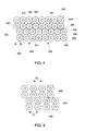
- the semi-staggered fin and tube heat exchanger 300 includes a number of tubes 310 protruding therethrough with a number of substantially spirally-wound circular fins 320 positioned thereon. Any number of tubes 310 and substantially spirally-wound circular fins 320 may be used herein.
- the semi-staggered fin and tube heat exchanger 300 may be relatively compact as compared to existing fin and tube heat exchangers, but may have any desired size, shape, and/or configuration.
- the semi-staggered fin and tube heat exchanger 300 may include the tubes 310 positioned in a semi-staggered relationship. Specifically, a first set 330 of tubes 310 may be staggered or transversely offset from a second set 340 of tubes 310. The first set 330 of tubes 310 may include a first row 332 and a second row 334 with the tubes 310 having an in-line position 331 with respect to a flow of air 305 therethrough. Furthermore, a plurality of tube pairs 335 (as indicated by the dotted line, FIG. 4 ) are defined in the first set of tubes 330, each tube pair 335 including one tube 310 in the first row 332 of tubes and one tube 310 in the second row 334 of tubes.
- the second set 340 of tubes 310 may include a third row 342 and a fourth row 344 with the tubes 310 therein also having the in-line position 331.
- a plurality of tube pairs 345 are defined in the second set of tubes 340, each tube pair 345 including one tube 310 in the third row 342 of tubes and one tube 310 in the fourth row 344 of tubes.
- pairs of tubes 310 are shown in the first set 330 and the second set 340, any number of rows 332, 334 and 342, 344 may be used herein with any number of tubes 310 therein. Where additional rows are included in each tube set, tube groupings, similar to tube pairs 335 and 345, may be defined therein.
- the first set 330 and the second set 340 may have an offset position 350 ( FIG. 4 ) with respect to each other to form the semi-staggered relationship.
- the offset position 350 may be about of half of the transverse spacing of a fin 320. More specifically, each subsequent tube row in a tube set, such as first set 330 or second set 340, is transversally offset by half the transversal spacing between the individual tubes 310. Other types of offsets, spacings, and configurations may be used herein.
- the semi-staggered fin and tube heat exchanger 300 may include the tubes 310 positioned in a semi-staggered relationship.
- the first set 330 of tubes 310 may be staggered or transversally offset from the second set 340 of tubes 310.
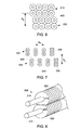
- Further spacing of the tubes 310 may include, and as best illustrated in FIG. 5 , a gap 400 between each tube pair 335 in the first set 330 of spirally wound circular fins 310 or each tube pair 345 in the second set 340 of spirally wound circular fins 310.
- each tube pairs 335, 345 may be spaced a transverse distance, D T , from a next tube pair 335, 345 dependent upon specific design requirements.
- further spacing of the tubes 310 may include a gap 400 between the first set 330 of spirally wound circular fins 310 and the second set 340 of spirally wound circular fins 310.
- the size and shape of the gap 400 may vary. More specifically, as illustrated in FIG. 6 , the first set of tubes 330 may be spaced a longitudinal distance, D L , from the second set of tubes 340 dependent upon specific design requirements.
- D L longitudinal distance
- further spacing of the tubes 310 may include a plurality of gaps 400 between each tube pair 335 in the first set 330 of spirally wound circular fins 310 or each tube pair 345 in the second set 340 of spirally wound circular fins 310, indicated at D T and a gap 400 between the first set 330 of spirally wound circular fins 310 and the second set 340 of spirally wound circular fins 310, indicated at D L .
- the design of the heat exchanger 300 may vary the longitudinal spacing (D L ) and transverse spacing (D T ) to meet the process or heat exchanger needs. It is anticipated that other types of positionings or spacings may be used herein. As is shown in FIGS.
- the fins 320 of the semi-staggered fin and tube heat exchanger 300 may be in the form of substantially spirally-wound circular fins 310.
- Each spirally-wound circular fin 310 may have a substantially concentric position 355 about each tube 310.
- each of the substantially spirally-wound circular fins 310 of the tube pair 335, 345 includes a cut portion 410.
- approximately 0.25" is cut off the fin height of 0.5 on one side of the fin structure.
- the cut portions 410 provide closer spacing of the tubes 310 in each tube pair 335, 345, and as a result, the distance between the rows 332, 334 and 342, 344 of each tube set 330, 340 may be minimized.
- an in-line tube arrangement generally has the benefit of a lower pressure loss while a staggered arrangement generally leads to higher heat transfer.
- the semi-staggered fin and tube heat exchanger 300 described herein thus combines the advantages of both positionings.
- the second row 334 of the first set 330 and the fourth row 344 of the second set 340 are generally positioned in the wake of the first row 332 of the first set 330 and the third row 342 of the second set 340, respectively.
- This staggered or transversely off-set position 350 thus reduces the aerodynamic profile drag that may account for part of the pressure loss, particularly given the relatively small distances between the in-line rows 332, 334 and 342, 344 of the tubes 310.
- staggering the first set 330 and the second set 340 of the tubes 310 may generate or enhance horseshoe and wake vortices so as to enhance heat transfer on the substantially spirally wound circular fins 320.
- the semi-staggered tube arrangement of the described fin and tube heat exchanger 300 aims at a reduction of pressure loss by forming the tube pairs 335, 345, comprised of a tube 310 of every first 332 and second row 334 in-line to the flow direction 305, while every consecutive third 342 and fourth 344 row is staggered with an offset of half the transverse spacing (D T ).
- D T transverse spacing
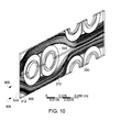
- a CFD model was set up to make use of symmetries and periodic inlet-outlet conditions.
- the geometry tested included solid fins having approximately a 2" OD and including cut portions 410 on one side to a height of approximately 0.25" to make the in-line tubes 310 fit tightly together.
- the mass flux corresponds to the experimental mass flow of 400 g/s.
- the results plot shows the streamlines 500 the heat transfer coefficients on the fins 320 and tubes 310.
- the heat transfer coefficients are highest on a leading edge 312 of the fins 310 of the first row 332. In between the in-line tubes 310 little fluid passes over the fins 320, leading to the low heat transfer coefficient and heat flux.
- the fins 320 act merely to conduct and transfer the heat circumferentially towards the inside of the tube..
- the distribution of the local heat transfer coefficients over the fins 320 appears quite uneven, ranging from 10 W/m 2 K between the in-line tubes 310 to more than 100 W/m 2 K at the leading edge 312 of the fins 320 and on the tube wall facing the flow 305.
- the average heat transfer coefficient on a second fin 320 of an in-line tube pair 335, 345 is lower than on the fin 320 facing the flow 305.
- a local maximum exists at the trailing edge 322 of the second fin 320, caused by an eddy vortex in the recirculation zone.
- the surface heat flux (not shown) distribution essentially follows the heat transfer coefficient, but the difference of the average over the first and second fin 320 is less pronounced, supporting the case for this arrangement as the second fin 320 contributes almost as much to heat transfer as the first. Furthermore, quantitative results show that the ratio of air-side conductivity over pressure loss for this configuration is high, indicating that for a given mass flux and overall conductivity such a heat exchanger would offer a low pressure loss penalty.
- the semi-staggered fin and tube heat exchanger 300 thus provides the staggered sets 330, 340 of the tubes 310 with the offset position 350.
- Each tube 310 may have a number of substantially spirally wound circular fins 320 thereon.
- This tube arrangement aims at a reduction of pressure loss by setting two tubes of every first and second row in-line to the flow direction, while every consecutive third and fourth row is staggered with an offset of half the transverse spacing. With the in-line rows spaced closely longitudinal, this leads to a reduction in profile drag as only half the tubes cross-sectional areas are facing the flow.
- the fins 320 may include cut portions 410 so as to minimize the distance between the rows, 332, 334 and 342, 344 of each tube pair 335, 345 in each set 330, 340 while the fins 310 may also have small gaps 400 therebetween.
- the semi-staggered fin and tube heat exchanger 300 thus provides a lower pressure loss as compared to conventional fin and tube designs with a higher heat transfer per tube. Additional technical advantages of the semi-staggered fin and tube heat exchanger 300 described herein are due to the utilization of standard circular tubes.
- the substantially spirally wound circular tubes 310 described herein have excellent pressure characteristics.
- a heat exchanger utilizing the fin and tube heat exchanger 300 design described herein may operate at a wide range of pressures with no risk of tube deformation or bursting, that may be an issue with alternative oval tubes. In addition, no re-tooling of the tube production line is necessary.
- the tubes utilized may be standard finned substantially circular tubes known in the art. Implementation of the embodiments of the fin and tube heat exchanger 300 described herein may require a modified header design that is easily accomplished.
- the semi-staggered fin and tube heat exchanger 300 may be more compact with lower operating costs and fewer tube rows for a given duty.
- the semi-staggered fin and tube heat exchanger 300 may be used for a variety of gas to liquid or gas to steam heat transfer applications and specifically may be used for power plant operations and the like. Smaller, better, and less expensive heat exchangers generally provide for a more cost effective energy system with a smaller footprint and lower operating costs.
Landscapes
- Engineering & Computer Science (AREA)
- Physics & Mathematics (AREA)
- Thermal Sciences (AREA)
- Mechanical Engineering (AREA)
- General Engineering & Computer Science (AREA)
- Geometry (AREA)
- Heat-Exchange Devices With Radiators And Conduit Assemblies (AREA)
Applications Claiming Priority (1)
| Application Number | Priority Date | Filing Date | Title |
|---|---|---|---|
| US13/149,146 US20120305227A1 (en) | 2011-05-31 | 2011-05-31 | Fin and tube heat exchanger |
Publications (1)
| Publication Number | Publication Date |
|---|---|
| EP2530420A2 true EP2530420A2 (fr) | 2012-12-05 |
Family
ID=46207872
Family Applications (1)
| Application Number | Title | Priority Date | Filing Date |
|---|---|---|---|
| EP12170007A Withdrawn EP2530420A2 (fr) | 2011-05-31 | 2012-05-30 | Ailette et échangeur de chaleur de tube |
Country Status (4)
| Country | Link |
|---|---|
| US (1) | US20120305227A1 (fr) |
| EP (1) | EP2530420A2 (fr) |
| BR (1) | BR102012012974A2 (fr) |
| CA (1) | CA2778749A1 (fr) |
Families Citing this family (2)
| Publication number | Priority date | Publication date | Assignee | Title |
|---|---|---|---|---|
| US20170356691A1 (en) * | 2016-06-10 | 2017-12-14 | Hayward Industries, Inc. | Swimming Pool Heat Exchangers And Associated Systems And Methods |
| CN109443053A (zh) * | 2018-10-30 | 2019-03-08 | 佛山科学技术学院 | 一种管壳式换热器 |
Family Cites Families (6)
| Publication number | Priority date | Publication date | Assignee | Title |
|---|---|---|---|---|
| US1844308A (en) * | 1927-03-09 | 1932-02-09 | Superheater Co Ltd | Heat exchanger |
| FR1368148A (fr) * | 1963-04-30 | 1964-07-31 | échangeur de chaleur en serpentins et sa fabrication | |
| US3934645A (en) * | 1974-02-01 | 1976-01-27 | Yuba Heat Transfer Corporation | Finned tube protector |
| DE3331186A1 (de) * | 1983-08-30 | 1985-03-14 | Spiro Research B.V., Helmond | Heizungsrohr mit eckigem bedrahtungsprofil |
| US6178770B1 (en) * | 1998-10-22 | 2001-01-30 | Evapco International, Inc. | Ice-on-coil thermal storage apparatus and method |
| US7296620B2 (en) * | 2006-03-31 | 2007-11-20 | Evapco, Inc. | Heat exchanger apparatus incorporating elliptically-shaped serpentine tube bodies |
-
2011
- 2011-05-31 US US13/149,146 patent/US20120305227A1/en not_active Abandoned
-
2012
- 2012-05-30 BR BR102012012974-4A patent/BR102012012974A2/pt not_active IP Right Cessation
- 2012-05-30 EP EP12170007A patent/EP2530420A2/fr not_active Withdrawn
- 2012-05-30 CA CA2778749A patent/CA2778749A1/fr not_active Abandoned
Non-Patent Citations (1)
| Title |
|---|
| None |
Also Published As
| Publication number | Publication date |
|---|---|
| US20120305227A1 (en) | 2012-12-06 |
| CA2778749A1 (fr) | 2012-11-30 |
| BR102012012974A2 (pt) | 2014-12-09 |
Similar Documents
| Publication | Publication Date | Title |
|---|---|---|
| US10527354B2 (en) | Modular air cooled condenser apparatus and method | |
| US11248850B2 (en) | Heat exchanger with interspersed arrangement of cross-flow structures | |
| CN101509427A (zh) | 用于提高燃气轮机功率输出的排气道及发电系统 | |
| EP2584157B1 (fr) | Générateur de vapeur à récupération de chaleur et procédés de couplage associés à une centrale à cycles combinés | |
| US10502493B2 (en) | Single pass cross-flow heat exchanger | |
| US20050279080A1 (en) | Heat exchanger with header tubes | |
| KR101795039B1 (ko) | 핀 및 튜브 열교환기 | |
| EP2455592A1 (fr) | Turbes de transfert thermique | |
| US20100043442A1 (en) | Dimpled serrated fintube structure | |
| EP2530420A2 (fr) | Ailette et échangeur de chaleur de tube | |
| CN105464725A (zh) | 采用自然通风冷却塔的直接空冷发电系统 | |
| US20090308051A1 (en) | Heat exchanger tube and air-to-air intercooler | |
| US20180066548A1 (en) | Combined cycle power plant having an integrated recuperator | |
| US11879691B2 (en) | Counter-flow heat exchanger | |
| US20120186253A1 (en) | Heat Recovery Steam Generator Boiler Tube Arrangement | |
| CN104633938B (zh) | 电锅炉换热器 | |
| CN113175419B (zh) | 风力发电机外部换热器弧形排布结构 | |
| CN113027710B (zh) | 风力发电机外部换热器双排布置结构 | |
| WO2024157091A1 (fr) | Tube à ailettes partielles pour échangeur de chaleur | |
| US20190011149A1 (en) | Sectional heat exchanger for use in a heat cell | |
| JP2000146101A (ja) | 排熱回収ボイラ装置 |
Legal Events
| Date | Code | Title | Description |
|---|---|---|---|
| PUAI | Public reference made under article 153(3) epc to a published international application that has entered the european phase |
Free format text: ORIGINAL CODE: 0009012 |
|
| AK | Designated contracting states |
Kind code of ref document: A2 Designated state(s): AL AT BE BG CH CY CZ DE DK EE ES FI FR GB GR HR HU IE IS IT LI LT LU LV MC MK MT NL NO PL PT RO RS SE SI SK SM TR |
|
| AX | Request for extension of the european patent |
Extension state: BA ME |
|
| STAA | Information on the status of an ep patent application or granted ep patent |
Free format text: STATUS: THE APPLICATION IS DEEMED TO BE WITHDRAWN |
|
| 18D | Application deemed to be withdrawn |
Effective date: 20161201 |