EP2530221A2 - Poolauskleidungshaltesystem - Google Patents
Poolauskleidungshaltesystem Download PDFInfo
- Publication number
- EP2530221A2 EP2530221A2 EP12170308A EP12170308A EP2530221A2 EP 2530221 A2 EP2530221 A2 EP 2530221A2 EP 12170308 A EP12170308 A EP 12170308A EP 12170308 A EP12170308 A EP 12170308A EP 2530221 A2 EP2530221 A2 EP 2530221A2
- Authority
- EP
- European Patent Office
- Prior art keywords
- edge
- panel
- panels
- interlocking
- interlocked
- Prior art date
- Legal status (The legal status is an assumption and is not a legal conclusion. Google has not performed a legal analysis and makes no representation as to the accuracy of the status listed.)
- Withdrawn
Links
- 238000000034 method Methods 0.000 claims abstract description 22
- 239000012528 membrane Substances 0.000 claims description 56
- 239000000463 material Substances 0.000 claims description 31
- 238000010276 construction Methods 0.000 claims description 19
- 230000009182 swimming Effects 0.000 claims description 16
- 230000001419 dependent effect Effects 0.000 claims 1
- 230000003014 reinforcing effect Effects 0.000 description 63
- 239000002689 soil Substances 0.000 description 8
- 229910052751 metal Inorganic materials 0.000 description 6
- 239000002184 metal Substances 0.000 description 6
- 230000015572 biosynthetic process Effects 0.000 description 5
- 238000013461 design Methods 0.000 description 5
- 239000000945 filler Substances 0.000 description 4
- -1 gravel Substances 0.000 description 4
- 229910000831 Steel Inorganic materials 0.000 description 3
- 238000009412 basement excavation Methods 0.000 description 3
- 238000010079 rubber tapping Methods 0.000 description 3
- 239000007787 solid Substances 0.000 description 3
- 239000010959 steel Substances 0.000 description 3
- 229910052782 aluminium Inorganic materials 0.000 description 2
- XAGFODPZIPBFFR-UHFFFAOYSA-N aluminium Chemical compound [Al] XAGFODPZIPBFFR-UHFFFAOYSA-N 0.000 description 2
- 238000005452 bending Methods 0.000 description 2
- 238000003780 insertion Methods 0.000 description 2
- 230000037431 insertion Effects 0.000 description 2
- 238000004519 manufacturing process Methods 0.000 description 2
- 230000013011 mating Effects 0.000 description 2
- 150000002739 metals Chemical class 0.000 description 2
- 238000012986 modification Methods 0.000 description 2
- 230000004048 modification Effects 0.000 description 2
- 239000002991 molded plastic Substances 0.000 description 2
- 239000004033 plastic Substances 0.000 description 2
- 229920003023 plastic Polymers 0.000 description 2
- 230000002787 reinforcement Effects 0.000 description 2
- XLYOFNOQVPJJNP-UHFFFAOYSA-N water Substances O XLYOFNOQVPJJNP-UHFFFAOYSA-N 0.000 description 2
- 239000004743 Polypropylene Substances 0.000 description 1
- 230000003466 anti-cipated effect Effects 0.000 description 1
- 238000005553 drilling Methods 0.000 description 1
- 230000001747 exhibiting effect Effects 0.000 description 1
- 239000003000 extruded plastic Substances 0.000 description 1
- 239000000835 fiber Substances 0.000 description 1
- 239000011519 fill dirt Substances 0.000 description 1
- 239000011521 glass Substances 0.000 description 1
- 238000010348 incorporation Methods 0.000 description 1
- 238000001746 injection moulding Methods 0.000 description 1
- 238000005304 joining Methods 0.000 description 1
- 229920001155 polypropylene Polymers 0.000 description 1
- 239000012779 reinforcing material Substances 0.000 description 1
- 238000009877 rendering Methods 0.000 description 1
- 239000011435 rock Substances 0.000 description 1
- 238000007665 sagging Methods 0.000 description 1
- 125000000391 vinyl group Chemical group [H]C([*])=C([H])[H] 0.000 description 1
- 229920002554 vinyl polymer Polymers 0.000 description 1
- 238000003466 welding Methods 0.000 description 1
- 239000002023 wood Substances 0.000 description 1
Images

Classifications
-
- E—FIXED CONSTRUCTIONS
- E04—BUILDING
- E04H—BUILDINGS OR LIKE STRUCTURES FOR PARTICULAR PURPOSES; SWIMMING OR SPLASH BATHS OR POOLS; MASTS; FENCING; TENTS OR CANOPIES, IN GENERAL
- E04H4/00—Swimming or splash baths or pools
- E04H4/0018—Easily movable or transportable swimming pools
- E04H4/0043—Easily movable or transportable swimming pools mainly made of panels
-
- E—FIXED CONSTRUCTIONS
- E04—BUILDING
- E04B—GENERAL BUILDING CONSTRUCTIONS; WALLS, e.g. PARTITIONS; ROOFS; FLOORS; CEILINGS; INSULATION OR OTHER PROTECTION OF BUILDINGS
- E04B2/00—Walls, e.g. partitions, for buildings; Wall construction with regard to insulation; Connections specially adapted to walls
- E04B2/84—Walls made by casting, pouring, or tamping in situ
- E04B2/86—Walls made by casting, pouring, or tamping in situ made in permanent forms
- E04B2/8664—Walls made by casting, pouring, or tamping in situ made in permanent forms using flexible material as form leaves
-
- E—FIXED CONSTRUCTIONS
- E04—BUILDING
- E04H—BUILDINGS OR LIKE STRUCTURES FOR PARTICULAR PURPOSES; SWIMMING OR SPLASH BATHS OR POOLS; MASTS; FENCING; TENTS OR CANOPIES, IN GENERAL
- E04H4/00—Swimming or splash baths or pools
- E04H4/0075—Swimming or splash baths or pools made of concrete
- E04H4/0081—Swimming or splash baths or pools made of concrete with walls and floor cast in situ
-
- E—FIXED CONSTRUCTIONS
- E04—BUILDING
- E04H—BUILDINGS OR LIKE STRUCTURES FOR PARTICULAR PURPOSES; SWIMMING OR SPLASH BATHS OR POOLS; MASTS; FENCING; TENTS OR CANOPIES, IN GENERAL
- E04H7/00—Construction or assembling of bulk storage containers employing civil engineering techniques in situ or off the site
- E04H7/02—Containers for fluids or gases; Supports therefor
-
- F—MECHANICAL ENGINEERING; LIGHTING; HEATING; WEAPONS; BLASTING
- F16—ENGINEERING ELEMENTS AND UNITS; GENERAL MEASURES FOR PRODUCING AND MAINTAINING EFFECTIVE FUNCTIONING OF MACHINES OR INSTALLATIONS; THERMAL INSULATION IN GENERAL
- F16B—DEVICES FOR FASTENING OR SECURING CONSTRUCTIONAL ELEMENTS OR MACHINE PARTS TOGETHER, e.g. NAILS, BOLTS, CIRCLIPS, CLAMPS, CLIPS OR WEDGES; JOINTS OR JOINTING
- F16B5/00—Joining sheets or plates, e.g. panels, to one another or to strips or bars parallel to them
- F16B5/06—Joining sheets or plates, e.g. panels, to one another or to strips or bars parallel to them by means of clamps or clips
- F16B5/0692—Joining sheets or plates, e.g. panels, to one another or to strips or bars parallel to them by means of clamps or clips joining flexible sheets to other sheets or plates or to strips or bars
-
- E—FIXED CONSTRUCTIONS
- E04—BUILDING
- E04H—BUILDINGS OR LIKE STRUCTURES FOR PARTICULAR PURPOSES; SWIMMING OR SPLASH BATHS OR POOLS; MASTS; FENCING; TENTS OR CANOPIES, IN GENERAL
- E04H4/00—Swimming or splash baths or pools
- E04H4/14—Parts, details or accessories not otherwise provided for
- E04H2004/146—Fixing of liners
- E04H2004/147—Fixing of liners the liner edge being held in a slot
-
- F—MECHANICAL ENGINEERING; LIGHTING; HEATING; WEAPONS; BLASTING
- F16—ENGINEERING ELEMENTS AND UNITS; GENERAL MEASURES FOR PRODUCING AND MAINTAINING EFFECTIVE FUNCTIONING OF MACHINES OR INSTALLATIONS; THERMAL INSULATION IN GENERAL
- F16B—DEVICES FOR FASTENING OR SECURING CONSTRUCTIONAL ELEMENTS OR MACHINE PARTS TOGETHER, e.g. NAILS, BOLTS, CIRCLIPS, CLAMPS, CLIPS OR WEDGES; JOINTS OR JOINTING
- F16B5/00—Joining sheets or plates, e.g. panels, to one another or to strips or bars parallel to them
- F16B5/0004—Joining sheets, plates or panels in abutting relationship
- F16B5/0008—Joining sheets, plates or panels in abutting relationship by moving the sheets, plates or panels substantially in their own plane, perpendicular to the abutting edge
- F16B5/0012—Joining sheets, plates or panels in abutting relationship by moving the sheets, plates or panels substantially in their own plane, perpendicular to the abutting edge a tongue on the edge of one sheet, plate or panel co-operating with a groove in the edge of another sheet, plate or panel
Definitions
- This document relates to a pool liner retaining system, and in particular to a pool wall structure that includes a plurality of interlocked panels for constructing a pool.
- the construction of swimming pools involves a series of steps that includes excavation of soil, formation of a pool wall structure, and then the completion of the remaining portions of the pool, such as the pool lining and pool deck.
- the formation of the pool wall structure is a particularly crucial and labor-intensive phase of the pool construction process.
- the pool wall structure must conform to the dimensions and design features of the pool design, such as wall curvature, while also providing structurally sound support to contain the weight of the pool water within the pool after construction.
- Pool designs featuring a vinyl liner supported by a surrounding pool wall structure have greatly simplified the pool construction process.
- the assembly of the pool wall structure remains a relatively labor intensive task using existing pool construction methods.
- Some existing construction methods rely on aligning continuous sheets of material that surround the perimeter of the pool to construct the pool wall structure; however, pool wall structures constructed using this method are difficult to maintain in a vertical aligned position required during the initial placement of the sheets and the pouring of reinforcing concrete around the outer perimeter of the pool wall structure during construction.
- modular panels that are fastened together at their edges to form the pool wall structure.
- modular panels are typically assembled using any number of tools and fasteners, thereby making the assembly process relatively more difficult and time consuming.
- a variety of sizes and shapes of modular panels may be required, thereby further increasing the complexity of the pool construction process.
- the pool wall structures formed from existing modular panels may still be difficult to maintain in position during the pouring of concrete.
- modular panels that are either hollow or incorporate a concrete form, such as a chimney, to contain an amount of reinforcing concrete being poured.
- these methods require considerably less reinforcing concrete, it is difficult to direct the concrete into the hollow panels or chimneys during the construction process, and typically the reinforcing concrete must be poured in phases to avoid the sagging of the modular panels or other alignment issues.
- the modular panel is only supported in the discrete regions adjacent or proximate to the chimneys, and therefore the remaining areas of the modular panels may be vulnerable to structural failures over time.
- these modular panels like the modular panels described previously, remain relatively complex to assemble.
- a pool wall structure may include a plurality of interlocking panels forming a continuous closed wall around the perimeter of a pool, wherein each of the plurality of interlocking panels comprises a male flexible portion and a female flexible portion situated on opposite sides of an interlocked edge between an adjacent pair of interlocking panels within the plurality of interlocking panels, and wherein the male flexible portion and the female flexible portion deform along an axis parallel to the interlocked edge to form a faceted curve shape within the continuous closed wall.
- a pool wall structure may include a plurality of interlocked panels forming a continuous closed wall around the perimeter of a pool, wherein each of the plurality of interlocking panels includes a concrete support contained within a support membrane attached to each of the plurality of interlocking panels along an interlocked edge between any adjacent pair of interlocking panels of the plurality of interlocking panels.
- a pool wall structure may include a plurality of interlocking panels forming a continuous closed wall around the perimeter of a pool, wherein each of the plurality of interlocking panels comprises a male edge and a female edge formed opposite to the male edge with the male edge of each of the plurality of panels being interlocked with a corresponding female edge of an adjacent one of the plurality of interlocking panels.
- Each of the plurality of interlocking panels may further include a concrete support contained within a support membrane, wherein the support membrane is attached to each of the plurality of interlocking panels along an interlocked edge comprising an interlocked male edge and female edge.
- a panel for the construction of a pool wall structure may include a flat body portion defining a male edge and a female edge.
- a male flexible portion may be positioned adjacent to the male edge having a first deformable region extending along the height of the panel, while a female flexible portion may be positioned adjacent to the female edge having a second deformable region extending along the height of the panel.
- the male edge extends along a height of the flat body portion and includes a male side plate and a tongue and the female edge is positioned opposite to the male edge and includes a groove and a keeper, wherein the groove is shaped to receive a second tongue of a second panel in an interlocked tongue-and-groove arrangement.
- the keeper may include a first and a second flange forming a channel shaped to receive a support membrane flap and a retaining rod.
- a method of constructing a pool wall structure may include:
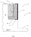
- FIG. 1 is a simplified illustration of a swimming pool construction site showing a pool wall structure
- FIG. 2 is a partial cross-sectional view of the pool wall structure.
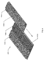
- FIG. 3 is a perspective view of an inner surface of an assembled section of the pool wall structure
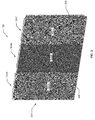
- FIG. 4 is a simplified illustration of an outer surface of the assembled section of the pool wall structure showing a plurality of interlocking panels
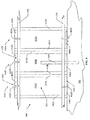
- FIG. 5 is a perspective view of a partially assembled section of the pool wall structure showing the engagement of the interlocking panels
- FIG. 6 is a top view of two mating edges of two adjacent interlocking panels illustrating the engagement between the interlocking panels:
- FIG. 7 is a cross-sectional view of a keeper for retaining a support membrane of the pool liner retaining system
- FIG. 8 is a top view of an assembled section of interlocking panels with the attached support membrane illustrating before and after the addition of the concrete within the support membrane;
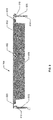
- FIG. 9 is a bottom view of one of the plurality of interlocking panels.
- FIG. 10 is a front view of another embodiment of one the plurality of plurality of panels.
- a pool liner retaining system having a pool wall structure, which is a modular structure having a plurality of interlocking panels with associated concrete supports formed within membrane pockets attached at the edges of each respective interlocking panel.
- the design of the interlocking panels overcomes many of the issues associated with existing pool wall structures.
- the sliding engagement of the interlocking panels along their edges in a tongue-and-groove arrangement is a joining mechanism that may be accomplished without the use of on-site tools, and results in the precise arrangement of the interlocking panels.
- the inclusion of flexible regions near the edges of each interlocking panel allows the interlocking panels to be arranged in a wide variety of faceted curved shapes with either positive or negative curvature without the need for custom-built curved panels to accomplish the same.
- the concrete molds forming the concrete support structures are fabricated through the attachment of a support membrane at the mating edges of each interlocking panel using a simple, tool-free pool liner retaining system such that the resulting concrete support extends over a significantly larger area of the pool wall structure compared to existing panel-based pool wall structures.
- a pool wall structure may be constructed of a plurality of interlocking panels 104 that are slideably engaged to each interlocking panel at respective adjoining edges to construct a swimming pool 10.
- the swimming pool 10 may be an in-ground pool formed by excavating the soil beneath a landscape surface 112 to form an excavated volume 111.
- the excavated volume 111 may be formed by a pool bottom 102 that defines the lower surface of the swimming pool 10 and an over-dig 110 that forms a horizontal surface at a depth below the landscape surface 112 corresponding to the bottom portion of a plurality of interlocking panels 104 forming the pool wall structure 100.
- Each interlocking panel 104 may be structurally reinforced by a concrete support 106 that extends the full height and width of each interlocking panel 104.
- each concrete support 106 is surrounded by a respective interlocking panel 104 and a support membrane 108 is attached to each edge of the respective panel 104.
- the plurality of interlocking panels 104 may be engaged together in a sliding tongue-and-groove engagement to form faceted curved shapes 114 due to the incorporation of flexible regions near the edges of each interlocking panel 104 as described greater in detail below.
- FIG. 2 A cross-section of the swimming pool 10 illustrating the pool wall structure 100 is shown in FIG. 2 .
- the excavation may be dug directly into the soil 202 and extend the full depth of the swimming pool 10 from the landscape surface 112 to the pool bottom 102.
- the over-dig 110 may extend outwardly from the pool volume 103 forming an over-dig lower surface 204.
- the interlocking panels 104 forming the pool wall structure 100 may rest on the over-dig lower surface 204 and further held in position by a concrete locking ring 206 poured into the over-dig 110 to overlap with a bottom portion of each panel 104.
- each concrete support 106 may contact and adhere to the concrete locking ring 206, thereby forming a continuous structural support for the pool wall structure 100.
- the concrete locking ring 206 and each concrete support 106 may be coincidentally poured and cured together, forming a continuous concrete structural support for the pool wall structure 100.
- the pool wall structure 100 may further include an upper reinforcing member 208 and a lower reinforcing member 210. Both the upper and lower reinforcing members 208 and 210 may extend continuously around the perimeter of the pool wall structure 100 adjacent or proximate to the upper and lower ends of the interlocking panels 104.
- the upper and lower reinforcing members 208 and 210 may include a series of discrete elongate pieces that are mechanically attached or spliced to one another to form continuous reinforcing bands around the upper and lower portions of the pool wall structure 100, respectively.
- the remaining volume of the over-dig 110 that is not occupied by either the locking ring 206 or the concrete supports 106 may be filled in with a filler material 212.
- a filler material 212 any known construction backfill material may be used as a filler material, including but not limited to concrete, crushed rock, gravel, fill dirt, topsoil, and any combination thereof.
- the pool wall structure 100 is made up of a plurality of interlocking panels 104.
- a representative section 300 of the pool wall structure 100 is illustrated in FIG. 3 .
- Each of the interlocking panels 104 includes a respective flat body portion 302, designated 302A, 302B, and 302C.
- the interlocking panel 104B may be interlocked with corresponding adjacent interlocking panels 104A and 104C, to form a flat pool wall surface 304 that extends over the entire perimeter of the pool wall structure 100.
- a pool liner (not shown) may be supported by the pool wall structure 100 such that the pool liner covers the pool wall surface 304 and the remaining interior surface of the swimming pool 10.
- each interlocking panel 104 may have been an overall height of about 4 feet and an overall width of about 12 inches. In other embodiments, the panels 104 may have a variety of overall widths ranging between 4 inches to 12 inches, while the overall height may range between 42 inches to 48 inches in order to accommodate a wider range of pool wall contours.
- an interlocking panel 104 may have substantially the same configuration of the other interlocking panels 104 except the interlocking panel 104 of FIG. 10 may define a body 109 that defines a rear surface 113 in which ribbing 118 is defined along the rear surface 113.
- the ribbing 118 is configured to provide structural support to the interlocking panel 104 such that the interlocking panel 104 may withstand the pressure applied by the concrete used to form the concrete support 106 including preventing deflection of the interlocking panels 104, such as bending or curvature of any kind.
- the interlocking panels 104 may be constructed of any suitable material capable of being fabricated with the shapes and structures described herein below. Non-limiting examples of suitable materials include metals such as steel or aluminum, and molded plastics. In one aspect, the interlocking panels 104 may be constructed from a material including polypropylene with a glass filler material.
- various substructures of the interlocking panels 104 described herein below including but not limited to the upper and lower panel plates, male and female side plates, and the flat panel body may be fabricated as an integrated structure from a molded plastic using any known process including but not limited to injection molding.
- Other panel structures and parts may be fabricated from additional materials, as described herein below.
- FIG. 4 a simplified illustration of the section 300 of the pool wall structure 100 viewed opposite to the flat pool wall surface 304 ( FIG. 3 ) is shown.
- the opposite sides of the flat body portions 302A-302C are shown interlocked as previously shown in FIG. 3 .
- an upper panel plate 406 and a lower panel plate 408 may extend perpendicularly outward from the flat body portion 302 at the upper and lower edges of each interlocking panel 104, respectively.
- the upper reinforcing member 208 may be attached to a respective upper panel plate 406, designated 406A -406C, using one or more fasteners 402. The attachment of the upper reinforcing member 208 to each upper panel plate 406 enhances the structural integrity of the pool wall structure 100.
- the lower reinforcement member 210 may be attached to a respective lower panel plate 408, designated 408A-408C, using one or more fasteners 402, designated 402D and 402E.
- the upper and lower reinforcing members 208 and 210 may be shaped into straight or curved sections to follow the specified curvature and contour of each section 300 of the pool wall structure 100.
- the upper reinforcing member 208 and lower reinforcing member 210 are constructed to resist structural loads imposed on the interlocking panels 104 due to the weight of the concrete during the pouring of the locking ring 206 ( FIG. 2 ) and the concrete supports 106 ( FIG. 2 ) to maintain the position of the interlocking panels 104 in their specified locations.
- the upper and lower reinforcing members 208 and 210 may provide the structural integrity of the pool wall structure 100 under the hydrodynamic pressure loads imposed on the pool wall surface 304 after the completed pool 10 is filled with water for use.
- the upper and lower reinforcing members 208 and 210 may be constructed using any known rigid elongate structural member including but not limited to tubular members, such as tubular steel and solid-section elongate members, such as rebar.
- the upper and lower reinforcing members 208 and 210 may be constructed from tubular steel stock having a square or rectangular cross-sectional shape.
- the cross-sectional dimensions and materials of the upper and lower reinforcing members 208 and 210 may be selected based on any one or more of at least several factors, including but not limited to: the anticipated maximum structural loads on the pool wall structure 100, the overall size and shape of the pool 10, the structural dimensions of the upper panel plate 406 and lower panel plate 408, the desired total weight of the upper and lower reinforcing members 208 and 210 and any combination thereof.
- the upper reinforcing member 208 and the lower reinforcing member 210 may be constructed from the same elongate material stock, or each of the upper and lower reinforcing members 208 and 210 may be constructed from different elongate material stocks.
- the fasteners 402 used to attach the upper reinforcing member 208 to the upper panel plate 406 as well as attach the lower reinforcing member 210 to the lower panel plate 408 may be any known fastener, such as self-tapping screws, metal screws, bolts with threaded fittings within the upper and lower reinforcing members 208 and 210, nuts and bolts, rods and cotter pins, solid rivets, blind rivets, and any combination thereof.
- the upper and lower reinforcing members 208 and 210 typically extend over at least two adjacent interlocking panels 104.
- discrete pool wall sections 300 of two or more engaged interlocking panels 104 may be assembled at a remote site situated away from the pool construction area.
- an upper reinforcing member 208 extending about the total width of the pool wall section 300 may be attached to the upper panel plates 208, and a similarly-sized lower reinforcing member 210 may be attached to the lower panel plates 210.
- the reinforced pool wall sections 300 may be assembled together at the pool construction site and the ends of the upper reinforcing members 208 may be spliced together to form a continuous structural member.
- the ends of the lower reinforcing members 210 of the assembled pool wall sections may be spliced together.
- the splicing of the ends of the upper and lower reinforcing members 208 and 210 may be accomplished using any known materials and methods.
- the ends of the adjacent upper and lower reinforcing members 208 and 210 may be spanned using one of more splice plates (not shown) fastened to the inner or outer surfaces of the adjacent upper and lower reinforcing members 208 and 210.
- a tubular splice fitting sized to slip over the adjacent ends of each adjacent upper and lower members 208 and 210 or inside the inner lumens (not shown) of adjacent tubular upper and lower members 208 and 210 may span across the adjacent ends of the adjacent tubular upper and lower members 208 and 210.
- the splice plates and/or tubular splice fittings may be fastened to the one or more ends of the upper and lower reinforcing members 208 and 210 using any known fastening materials and methods, for example self-tapping screws, metal screws, bolts with threaded fittings within the upper and lower reinforcing members 208 and 210, splice plates, and/or tubular splice fittings, nuts and bolts, rods and cotter pins, solid rivets, blind rivets, and any combination thereof.
- the ends of adjacent upper and lower reinforcing members 208 and 210 may be directly joined using existing methods, such as welding.
- one or more reinforcing bars 404 may be included in the pool wall section 300.
- Each reinforcing bar 404 may extend downward through vertically-aligned holes drilled through the lower reinforcing member 210 as well as the lower panel plate 408 and into the soil 202 below the pool wall section 300.
- each reinforcing bar 404 may extend upward through a concrete support 106 associated with the panel 104, which holds each reinforcing bar 404 in position.
- the reinforcing bar 404 may extend upward to a distance from about three feet to about six feet above the upper edge of the interlocking panel 104, and may be bent over in a horizontal orientation in the region above the wall section 300 to form a supporting structure for a pool deck (not shown) around the perimeter of the swimming pool 10.
- the interlocking panel 104B may be interlocked with adjacent panels 104A and 104C at male edge 410B and female edge 412B of the interlocking panel 104B.
- the left/right locations of the male edge 410B and female edge 412C may be specified arbitrarily as long as the male and female edges 410B and 412C of panel 104B are consistently positioned for interlocking alignment with adjacent panels 104A and 104C.
- the male edge 410 and female edge 412 of the adjacent interlocking panels 104 may be engaged in a tongue-and-groove mechanism.
- the male edge 410B of interlocking panel 104B may interlock with the female edge 412C of adjacent interlocking panel 104C.
- the female edge 412B of interlocking panel 104B may interlock with the male edge 410A of the adjacent interlocking panel 104A.
- the male edge 410C of interlocking panel 104C would be engaged to the female edge 412 of another adjacent interlocking panel 104 (not shown), while female edge 412A of interlocking panel 102A would be engaged to the male edge 410 of another adjacent interlocking panel 104 (not shown).
- Each of the adjacent interlocking panels 104 may be joined by sliding adjoining respective male and female edges 410A and 412B relative to each other in a direction parallel to the male and female edges 410A and 412B, as illustrated in FIG. 5 .
- the male edge 410A includes a protruding edge which fits into a corresponding slot included within the female edge 412B.
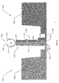
- FIG. 6 A cross-sectional view of interlocking panels 104A and 104B is illustrated in FIG. 6 .
- the male edge 410A of interlocking panel 104A may include a tongue 602, which extends approximately the full height of the interlocking panel 104A in the form of a protruding ridge.
- the cross-sectional profile of the tongue 602 substantially matches the profile of a groove 604 formed in the material of the female edge 412B of the adjacent interlocking panel 104B.
- the tongue 602 and groove 604 of adjacent interlocking panels 104 mechanically fit together in a tongue-and-groove configuration, thereby fastening adjoining interlocking panels 104 without the use of specialized tools or separate fasteners, which significantly simplifies the process of assembling the pool wall structure 100. Further, the tight tolerances of the interlocked tongue 602 and groove 604 assure a precise alignment of interlocking panels 104 within the pool wall structure 100.
- each interlocking panel 104A and 104B includes a male side plate 614 associated with a male edge 410A and a female side plate 612 associated with the female edge 412B.
- the male side plate 614 and the female side plate 612 extend in a substantially perpendicular direction from the flat body 302 of the interlocking panel 104, and further extend in a direction parallel relative to the male and female edges 410A and 412B.
- a keeper 600 may also be included for providing an attachment fitting for the support membrane 108 ( FIG. 7 ) used to form the concrete support 106 ( FIG. 1 ).
- each keeper 600 may include a first flange 616 and a second flange 618 projecting in an outward direction from between the male side plate 614 and the female side plates 612.
- the first flange 616 and second flange 618 may be attached to a body 608 that is attached to the female edge 412B using at least two or more fasteners 610.
- the body 608 may be attached to the female side plate 612 using three fasteners spaced along the height of the female side panel 612.
- Any known fastener 610 may be used to attach the keeper body 608 to the female side plate 612, for example self-tapping screws, metal screws; nuts and bolts, solid rivets, blind rivets, and any combination thereof.
- the keeper body 608 may be a flat strip extending nearly the full length of the female side plate 612. When adjacent interlocking panels 104A and 104B are engaged, the body 608 may be interposed between the female side plate 612 and the male side plate 614, as shown in FIG. 6 .
- the free end 628 of the keeper body 608 opposite to the flanges 616 and 618 may partially overlap the groove 604. In this aspect, the free end 628 may fit into a corresponding slot 606 formed in the tongue 602 of the male edge 410.
- the keeper 600 may be attached to either the female or male side plates 612 and 614 of each interlocking panel 104, or the keeper 600 may be formed as an integral element of the interlocking panel 104.
- the keeper 600 may be formed from any known material exhibiting sufficient strength and fatigue resistance, including but not limited to plastics and metals.
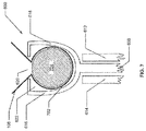
- the first and second flanges 616 and 618 form a channel 622 into which a fold of support membrane 108 and a retaining rod 704 may be inserted in order to anchor the support membrane 108 at the interlocked edges of the interlocking panels 104.
- An opening 620 situated between the flanges 616 and 618 provides external access for the fold of support membrane 108 without need for specialized tools.
- FIG. 7 is a cross-sectional view through the keeper 600, illustrating a flap of support membrane 702 held in place within the channel 622 by the retaining rod 704.
- the flap of support membrane 702 may be inserted through the opening 620 and into the channel 622 of the keeper 600.
- the retaining rod 704 may be inserted into the channel 622, causing the flap of support membrane 702 to be pressed against the inner surface of the channel 622, due to the relatively tight fit of the retaining rod 704 within the channel 622.
- One end of the retaining rod 704 may be inserted into an upper end of the channel 622 where the channel 622 opens at the upper end of the keeper 600.
- the retaining rod 704 may then be slid along the channel 622 in a downward direction parallel to side of the interlocking panel 104 until the retaining rod 704 occupies the full length of the channel 622. In this manner, the support membrane 108 may be attached to the pool wall structure 100 at the interlocked edges of the interlocking panels 104.
- the retaining rod 704 may be produced from any suitable materials, including but not limited to metal, wood, and plastic.
- suitable materials for the fabrication of the retaining rods 704 include extruded plastic and extruded aluminum.
- the length of the retaining rod 704 may be approximately equal to the overall length of the channel 622, and may be slightly longer than the channel to provide additional length to grip while inserting the retaining rod 704 into the channel 622.
- the retaining rod 704 may be configured to fit closely within the channel 622 while allowing sufficient space within the channel 622 for the flap of supporting membrane 702, and sufficient free space to slip the retaining rod 622 the full length of the channel 622 without need for excessive force and without damaging the supporting membrane 108.
- cross-sectional shapes may include a circular shape, square shape, triangular shape, elliptical shape, hexagonal shape, octagonal shape, or any combination thereof as long as the minimum cross-sectional dimension is larger than the width of the opening 620 of the channel 622.
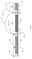
- the concrete support 106 may be formed by inserting concrete into a pocket 802, for example formed between the upper panel plate 406A and the support membrane 108A once the membrane 108A is attached to each of the respective keepers 600 on the interlocking panels 104A-104C.
- the secured support membrane 108 is sealed nearly the full height of the interlocking panels 104A-104C along each of the keepers 600.
- a top view of the support membrane 108 secured in the keepers 600 is illustrated in FIG. 8 before and after the addition of concrete to form the concrete support 106A and 106B, respectively.
- the support membrane 108A and interlocking panel 104A may form a pocket 802 that is open at its upper and lower ends. This pocket 802 provides a form for receiving concrete for fabrication of the concrete support 106.
- a certain amount of concrete may be inserted into the open upper end of the pocket 802, resulting in the formation of a concrete support 106.
- the support membranes 108B and 108C may stretch due to the weight of the inserted concrete between the support members 108B, 108C and upper panel plates 406B, 406C, respectively, that results in a rounded cross-sectional shape for the concrete supports 106A and 106B.
- the size and shape of the concrete support may be specified by any one or more of at least several factors, for example the amount of concrete added into the pocket 802, the thickness and/or elasticity of the supporting membrane material 108, the inclusion of reinforcing materials such as inextensible fibers into the support membrane 108, the tension of the secured supporting membrane 108 prior to the insertion of concrete, and any combination thereof.
- the concrete may migrate out of the lower end of the pocket 802 until an amount of concrete sufficient to effectively seal the lower end of the pocket 802 has accrued.
- the locking ring 206 ( FIG. 2 ) may be of sufficient height above the over-dig lower surface 204 to seal off the lower end of the pocket 802.
- the concrete used to produce the locking ring 206 may be poured prior to the insertion of the concrete into the pockets 802 to form the concrete supports 106.
- the concrete used to produce the locking ring 206 and the concrete supports 106 may be poured concurrently.
- each interlocking panel 104 may further include a male flexible portion 624 and a female flexible portion 626 as illustrated in FIGS. 6 and 9 .
- the male flexible portion 624 may be a thinner region of the flat body of the panel 302 that extends the full height of the interlocking panel 104 in a direction parallel with the male side plate 614 near the male edge 410 of the interlocking panel 104.
- the female flexible portion 626 may be a thinner region of the flat body of the panel 302 that extends the full height of the interlocking panel 104 in a direction substantially parallel with the female side plate 612 near the female edge 412 of the interlocking panel 104.
- the thinner material of the male and female flexible portions 624 and 626 results in a weakened region relative to the surrounding material of the flat body of panel 302, thereby rendering the male and female flexible portions 624 and 626 capable of deforming at an angle of up to about 30 degrees under sufficient bending moment. Because of the vertical orientation of the flexible portions 624 and 626, the ends of the panel deform about a vertical axis, thereby preserving the desired vertical orientation of all interlocking panels 104 in the pool wall structure 100.
- a wall section 300 may be formed using a plurality of interlocking panels 104 into a faceted curved shape 114 (see FIG. 1 ), in which the curvature is approximated by the flat faces of the interlocking panels 104 with discrete bends at the flexible portions 624 and 626.
- each interlocking panel 104 has an overall width of about 12 inches
- a curved wall with a radius of curvature as low as 2 feet may be assembled. Tighter curves may be assembled using panels with narrower widths including but not limited to 8 inches wide and 4 inches wide,
- the upper and lower panel plates 406 and 408 extend less than the full width of the interlocking panel 104 to accommodate a curvature in which the flat faces of the interlocking panels 104 are bent away from each other. In this aspect, if the upper and lower panel plates 406 and 408 extended the full width of the interlocking panels 104, the edges of the plates 406 and 408 near the interlocked edges of the interlocking panels 104 would physically interfere with each other if the interlocking panels 104 were bent with the flat faces away from each other.
- a pool wall structure 100 may be constructed using the interlocking panels 104 and associated materials, parts, and assembly methods described herein.
- the site at which the swimming pool 10 is to be constructed may be prepared by excavating a volume of soil 202 from beneath the landscape surface 112.
- the excavated volume 111 includes a deeper central portion forming the pool volume 103 which extends from the level of the landscape surface 112 down to the bottom surface of the pool 102.
- a shallower over-dig 110 is also excavated around the perimeter of the deeper central portion, which is sized to contain the pool wall structure 100.
- the over-dig 110 may extend down about 4 feet to accommodate the height of the interlocking panels 104.
- the over-dig 110 may also extend outwardly from the deeper central portion of the excavation from about 18 inches to about 36 inches to accommodate the width of the interlocking panel 104 and associated concrete supports 106, and to provide sufficient room for the on-site assembly of the components of the pool wall structure 100.
- the interlocking panels 104 may then be assembled by sliding the adjoining edges of each of the interlocking panels 104 along the height of the interlocking panel 104 to engage the tongue of each male edge within the groove of the female edge of the adjoining interlocking panel 104.
- the series of interlocking panels 104 may be arranged to form the desired pool wall configuration. If a curved pool wall section 114 is desired, the interlocking panels 104 may be bent at their male flexible portions 624 and female flexible portions 626 to form facets curved contours. The interlocking panels 104 may be engaged until the interlocking panels 104 form a closed surface around the entire perimeter of the swimming pool 10.
- the upper reinforcing member 208 may be fastened to the underside of the upper panel plates 406 of each interlocking panel 104 to form a continuous structural member.
- a series of holes may be drilled through the upper surfaces of the upper panel plates 406 and into the upper reinforcing member 208, and a fastener 402 such as a threaded screw may be installed within each hole to secure the upper reinforcing member 208 to each upper panel plate 406.
- the lower reinforcing member 210 may be fastened to the lower panel plate 408 by drilling a series of holes through the lower panel plates and into the lower reinforcing member 210 and installing a fastener 402 such as a threaded screw into each hole.
- a subset of the interlocking panels 104 may be assembled into a panel wall section 300 that may include from about 2 to about 30 interlocking panels 104.
- Each wall panel section 300 may form any wall contour including but not limited to a straight or flat wall contour or a curved contour.
- the panel wall sections 300 may be assembled remotely to the pool construction site and may further include an upper reinforcing member 208 and lower reinforcing member 210 fastened to the upper panel plates 406 and lower panel plates 408 respectively.
- the upper reinforcing member 208 and lower reinforcing member 210 may extend about the total width of the wall section 300.
- the panel wall sections 300 may be joined in the predetermined arrangement by sliding the adjoining male edges 410 and female edges 412 together to interlock the edges in the tongue-and-groove arrangement.
- Adjoining ends of respective upper reinforcing members 208 and lower reinforcing members 210 may be spliced together using additional materials such as splice plates or tubular splice fittings as described herein above.
- a number of reinforcing bars 404 may be inserted along the perimeter of the assembled interlocking panels 104.
- a hole may be drilled through the lower reinforcing member 210 and lower panel plate 408, and the reinforcing bar 404 may be inserted through the hole into the soil 202 beneath the over-dig surface 204.
- the reinforcing bars 404 may be inserted at any location relative to the interlocking panels 104 at any desired spacing.
- the reinforcing bars may also be situated such that the free ends of the reinforcing bars protrude through concrete supports 106 to provide enhanced structural integrity to the pool wall structure 100.
- the free ends of the reinforcing bars 404 may extend a height from about 2 feet to about 5 feet over the top of the interlocking panels 104.
- Each free end of each reinforcing bar 404 may be bent at a 90 degree angle outward relative the interlocking panels 104 such that the bent ends are aligned parallel to the surrounding landscape surface 112.
- the bent free ends of the reinforcing bars 404 may be used to form a support and/or reinforcement for a deck (not shown) surrounding the perimeter of the swimming pool 10.
- the support membrane 108 may be arranged around the outer perimeter of the assembled interlocking panels 104.
- the support membrane 108 may extend the entire perimeter of the interlocking panels 104 and may further extend about the full height of the interlocking panels 104.
- the support membrane 108 may have a height of about 4 feet to match the height of the interlocking panels 104.
- the support membrane 108 may be pieced together around the outer perimeter of the interlocking panels 104 by overlapping the ends of the support membrane 108 across one of the respective keepers 600.
- the support membrane 108 may be attached at the interlocked edges of adjacent interlocking panels 104 at each keeper 600.
- a vertical flap of the membrane 702 may be formed along the full height of the support membrane 108 and tucked into the opening of the keeper 620.
- One end of a retaining rod 704 may be inserted into inside of the vertical flap of the membrane 702 within of the channel 622 of the keeper 600 and slid downward along the full length of the channel 622, such that the vertical flap of the membrane 702 is pressed against the inner surface of the channel 622.
- the vertical flap of the membrane 702 may be similarly attached at each adjacent keeper 600 and repeated until the support membrane 108 has been secured to all keepers 600 around the outer perimeter of the interlocking panels 104.
- the support membrane 108 may be stretched taut between adjacent keepers 600 or an excess amount of support membrane 108 may be maintained between adjacent keepers 600, depending on the desired size and shape of the concrete supports 106 to be formed.
- a locking ring 206 may be formed by pouring concrete into the over-dig volume between the panels 104 and the surrounding soil 202.
- the locking ring 206 may have a height from about 6 inches to about 12 inches above the over-dig surface 204, and may extend outward from the panels 104 to a distance from about 18 inches to about 36 inches, depending on the width of the over-dig 110.
- the concrete supports 106 may be formed by inserting concrete into the pocket 802 formed between the interlocking panel 104 and the support membrane 108.
- the amount of concrete inserted into the pockets 802 may be specified in order to form a desired size and shape of the concrete supports 106.
- the concrete supports may be formed concurrently with the locking ring 206, or the concrete supports may be formed at a separate time after the formation of the locking ring 206.
- the remaining volume of the over-dig 110 that is not occupied by the locking ring 206, panels 104, or concrete supports 106 may be filled in with a filler material such as gravel, soil, or additional concrete, as described herein above.
Landscapes
- Engineering & Computer Science (AREA)
- Architecture (AREA)
- Civil Engineering (AREA)
- Structural Engineering (AREA)
- General Engineering & Computer Science (AREA)
- Mechanical Engineering (AREA)
- Physics & Mathematics (AREA)
- Electromagnetism (AREA)
- Revetment (AREA)
- Pit Excavations, Shoring, Fill Or Stabilisation Of Slopes (AREA)
Applications Claiming Priority (1)
| Application Number | Priority Date | Filing Date | Title |
|---|---|---|---|
| US201161492166P | 2011-06-01 | 2011-06-01 |
Publications (2)
| Publication Number | Publication Date |
|---|---|
| EP2530221A2 true EP2530221A2 (de) | 2012-12-05 |
| EP2530221A3 EP2530221A3 (de) | 2013-01-02 |
Family
ID=46201437
Family Applications (1)
| Application Number | Title | Priority Date | Filing Date |
|---|---|---|---|
| EP12170308A Withdrawn EP2530221A3 (de) | 2011-06-01 | 2012-05-31 | Poolauskleidungshaltesystem |
Country Status (2)
| Country | Link |
|---|---|
| US (1) | US8850773B2 (de) |
| EP (1) | EP2530221A3 (de) |
Families Citing this family (5)
| Publication number | Priority date | Publication date | Assignee | Title |
|---|---|---|---|---|
| US10280641B2 (en) | 2017-06-16 | 2019-05-07 | Bernard J. Kulkaski | Liquid containment pool wall using polymer sheeting |
| CN107724724B (zh) * | 2017-09-19 | 2024-10-29 | 北京国家游泳中心有限责任公司 | 一种拼装泳池壁及可拆卸的无边际泳池 |
| USD923825S1 (en) * | 2020-02-12 | 2021-06-29 | Latham Pool Products, Inc. | Surface portion of a pool or spa |
| USD924446S1 (en) * | 2020-02-12 | 2021-07-06 | Latham Pool Products, Inc. | Surface portion of a pool or spa |
| USD924445S1 (en) * | 2020-02-12 | 2021-07-06 | Latham Pool Products, Inc. | Surface portion of a pool or spa |
Family Cites Families (38)
| Publication number | Priority date | Publication date | Assignee | Title |
|---|---|---|---|---|
| US3468088A (en) * | 1966-04-14 | 1969-09-23 | Clarence J Miller | Wall construction |
| US3555751A (en) | 1968-08-16 | 1971-01-19 | Robert M Thorgusen | Expansible construction form and method of forming structures |
| US3564791A (en) | 1969-02-27 | 1971-02-23 | George F Arp | Swimming pool wall |
| US3673751A (en) | 1970-07-21 | 1972-07-04 | Champion Inc | Building and swimming pool construction |
| BE785357A (fr) * | 1970-10-12 | 1972-10-16 | Kdi Sylvan Pools | Piscine a elements modulaires |
| US3736599A (en) * | 1971-03-25 | 1973-06-05 | Carson B | Swimming pool construction |
| US3739539A (en) | 1971-06-15 | 1973-06-19 | Aqualand Pool Co Inc | Below ground swimming pool |
| US3812633A (en) | 1972-06-08 | 1974-05-28 | Champion Inc | Swimming pool construction |
| US3974605A (en) | 1974-06-10 | 1976-08-17 | Elcon Manufacturing Company Limited | Wall structure and swimming pool construction |
| US4047340A (en) | 1974-02-20 | 1977-09-13 | Fox Pool Corporation | Swimming pool modular constructure |
| US3971075A (en) | 1974-05-08 | 1976-07-27 | Heinbaugh Kenneth D | Swimming pool structure |
| US4015379A (en) | 1976-06-10 | 1977-04-05 | Colson Jr Andrew Elliott | In-ground swimming pool and apparatus and method for constructing same |
| US4055922A (en) | 1976-09-24 | 1977-11-01 | Heldor Associates, Inc. | Frame structure for swimming pool |
| US4090337A (en) | 1977-08-10 | 1978-05-23 | Medina Plastic Products, Inc. | Flexible form for cementitious slurry |
| US4177614A (en) | 1978-05-15 | 1979-12-11 | Heldor Associates, Inc. | Swimming pool wall of resin panels |
| US4263759A (en) | 1979-03-15 | 1981-04-28 | Bradley Enterprises, Inc. | Swimming pool construction and method of making the same |
| US4227361A (en) | 1979-03-16 | 1980-10-14 | Bradley Enterprises, Inc. | Method of constructing a swimming pool |
| US4297819A (en) | 1980-02-06 | 1981-11-03 | Heldor Associates, Inc. | Reinforced molded resin pool wall |
| US4432173A (en) | 1980-03-19 | 1984-02-21 | Carl R. Meyer | Swimming pool integral structural wall brace system |
| US4364211A (en) | 1980-12-08 | 1982-12-21 | Heldor Associates, Inc. | Pool panel connector system |
| FR2509352A1 (fr) | 1981-07-10 | 1983-01-14 | Dalbanne Jacques | Procede et dispositif pour la construction de piscines |
| US4635304A (en) | 1985-04-29 | 1987-01-13 | Cascade Industries, Inc. | Wall system for swimming pools |
| US5025061A (en) * | 1986-12-22 | 1991-06-18 | Nippon Oil And Fats Co., Ltd. | Aqueous dispersion coating material |
| FR2641811B1 (fr) | 1989-01-09 | 1992-09-11 | Desjoyaux Jean Louis | Panneau pour la realisation de piscines notamment, et son procede de fabrication |
| US4976088A (en) | 1989-02-03 | 1990-12-11 | Powers John W | Method for construction of an in-ground swimming pool |
| US5155872A (en) * | 1990-10-25 | 1992-10-20 | Aymes Doniel G | Swimming pool with interlocking wall panels and liner-receiving top rail |
| US5419656A (en) | 1991-11-08 | 1995-05-30 | Mckinnon; Gordon | Pool apparatus and method of making |
| FR2686364A1 (fr) * | 1992-01-16 | 1993-07-23 | Dufournet Laurent | Perfectionnement pour piscine. |
| US5330151A (en) * | 1992-07-29 | 1994-07-19 | Boyack John D | Partially reusable swimming pool wall form |
| US5590493A (en) * | 1995-07-06 | 1997-01-07 | Wilson; Jean | Wall structures for swimming pools |
| FR2740806B1 (fr) * | 1995-11-03 | 1998-02-06 | Andrei Sandra | Procede et dispositif de construction de piscine |
| FR2776323B1 (fr) | 1998-03-23 | 2000-05-05 | Piscines Desjoyaux Sa | Bloc compact de filtration pour bassin de piscine |
| FR2797651A1 (fr) * | 1999-08-18 | 2001-02-23 | Joel Huertas | Structure emboitable pour piscine hors sol de forme ronde |
| FR2799485B1 (fr) | 1999-10-11 | 2001-11-23 | Piscines Desjoyaux Sa | Systeme de canalisation pour dispositif de filtration et de pompage de l'eau d'un bassin de piscine |
| FR2846991B1 (fr) | 2002-11-08 | 2005-04-22 | Distrib Et D Equipement Soc De | Systeme pour realiser une cloison de retenue de liquide, telle une cloison de piscine, a partir de panneaux prefabriques |
| FR2846968B1 (fr) | 2002-11-08 | 2005-02-04 | Salles Jean Pierre | Nouveaux derives amphiphiles de l'alpha-c-phenyl-n-tert- butyl nitrone |
| FR2856332B1 (fr) | 2003-06-20 | 2007-03-23 | Piscines Desjoyaux Sa | Panneau pour la realisation d'un bassin de piscine |
| US8215069B2 (en) | 2007-05-11 | 2012-07-10 | Separation Llc | Swimming pool system with reinforced composite structural components |
-
2012
- 2012-05-31 EP EP12170308A patent/EP2530221A3/de not_active Withdrawn
- 2012-06-01 US US13/486,814 patent/US8850773B2/en active Active
Non-Patent Citations (1)
| Title |
|---|
| None |
Also Published As
| Publication number | Publication date |
|---|---|
| EP2530221A3 (de) | 2013-01-02 |
| US8850773B2 (en) | 2014-10-07 |
| US20120304582A1 (en) | 2012-12-06 |
Similar Documents
| Publication | Publication Date | Title |
|---|---|---|
| KR100730882B1 (ko) | 콘크리트벽체용 고저항성 폼웍 | |
| US3440780A (en) | Swimming pool wall construction | |
| US6698710B1 (en) | System for the construction of insulated concrete structures using vertical planks and tie rails | |
| AU633533B2 (en) | Panels for the production of swimming pools | |
| US8850773B2 (en) | Pool liner retaining system | |
| US20130087681A1 (en) | Insert panel for concrete fillable wall formwork | |
| US9388592B2 (en) | Methods of underwater seaming | |
| US10125468B2 (en) | Stay-in-place footing form assembly and method of use | |
| KR100495782B1 (ko) | 블록조립식 보강토옹벽 패널과 이 패널을 사용한보강토옹벽의 시공방법 | |
| CN103620120A (zh) | 组装式排水沟结构物 | |
| US7559176B2 (en) | Concrete fillable formwork wall | |
| US20090188180A1 (en) | Integrated wall system | |
| KR20130044855A (ko) | 전단키 결합방식의 조립식 프리캐스트 패널, 이를 이용한 벽체 및 그 시공방법 | |
| US20180112400A1 (en) | Insulated concrete form construction method and system | |
| US5794393A (en) | Concrete foundation wall form apparatus and method | |
| US8646756B2 (en) | Gate | |
| KR20140047924A (ko) | 거푸집이 필요없는 pc 판넬을 이용한 사면보강용 현장타설 계단식옹벽 대체시공법 | |
| US7770340B2 (en) | Method and apparatus for installing egress window steps | |
| KR101542602B1 (ko) | 건축용 가설 흙막이시설 | |
| JP2002213077A (ja) | コンクリート壁用組み型枠の構築方法ならびにこれに使用する鋼製型枠 | |
| AU2021107665B4 (en) | Swimming Pool Construction | |
| KR101979895B1 (ko) | 조립식 토류판 및 이를 이용한 흙막이 가시설 시공방법 | |
| KR102568888B1 (ko) | 합성데크형 조인트필라스터가 구비된 내진 지하연속벽 | |
| KR102351788B1 (ko) | 간편 지보재 연결장치 | |
| KR102606021B1 (ko) | 금속재 유지관리 통로를 구비한 플라스틱 저류조 및 그 시공방법 |
Legal Events
| Date | Code | Title | Description |
|---|---|---|---|
| PUAL | Search report despatched |
Free format text: ORIGINAL CODE: 0009013 |
|
| PUAI | Public reference made under article 153(3) epc to a published international application that has entered the european phase |
Free format text: ORIGINAL CODE: 0009012 |
|
| AK | Designated contracting states |
Kind code of ref document: A2 Designated state(s): AL AT BE BG CH CY CZ DE DK EE ES FI FR GB GR HR HU IE IS IT LI LT LU LV MC MK MT NL NO PL PT RO RS SE SI SK SM TR |
|
| AX | Request for extension of the european patent |
Extension state: BA ME |
|
| AK | Designated contracting states |
Kind code of ref document: A3 Designated state(s): AL AT BE BG CH CY CZ DE DK EE ES FI FR GB GR HR HU IE IS IT LI LT LU LV MC MK MT NL NO PL PT RO RS SE SI SK SM TR |
|
| AX | Request for extension of the european patent |
Extension state: BA ME |
|
| RIC1 | Information provided on ipc code assigned before grant |
Ipc: E04H 4/00 20060101AFI20121129BHEP Ipc: E04B 2/86 20060101ALI20121129BHEP Ipc: E04H 4/14 20060101ALN20121129BHEP Ipc: F16B 5/00 20060101ALI20121129BHEP Ipc: E04H 7/02 20060101ALI20121129BHEP |
|
| 17P | Request for examination filed |
Effective date: 20130626 |
|
| RBV | Designated contracting states (corrected) |
Designated state(s): AL AT BE BG CH CY CZ DE DK EE ES FI FR GB GR HR HU IE IS IT LI LT LU LV MC MK MT NL NO PL PT RO RS SE SI SK SM TR |
|
| STAA | Information on the status of an ep patent application or granted ep patent |
Free format text: STATUS: THE APPLICATION IS DEEMED TO BE WITHDRAWN |
|
| 18D | Application deemed to be withdrawn |
Effective date: 20151201 |