EP2529850A1 - Capteur d'angle de pliage et procédé de mesure d'un angle de pliage - Google Patents
Capteur d'angle de pliage et procédé de mesure d'un angle de pliage Download PDFInfo
- Publication number
- EP2529850A1 EP2529850A1 EP11168102A EP11168102A EP2529850A1 EP 2529850 A1 EP2529850 A1 EP 2529850A1 EP 11168102 A EP11168102 A EP 11168102A EP 11168102 A EP11168102 A EP 11168102A EP 2529850 A1 EP2529850 A1 EP 2529850A1
- Authority
- EP
- European Patent Office
- Prior art keywords
- housing
- bending angle
- angle sensor
- sliding block
- tastscheibe
- Prior art date
- Legal status (The legal status is an assumption and is not a legal conclusion. Google has not performed a legal analysis and makes no representation as to the accuracy of the status listed.)
- Granted
Links
- 238000005452 bending Methods 0.000 title claims abstract description 71
- 238000000034 method Methods 0.000 title claims abstract description 16
- 238000006073 displacement reaction Methods 0.000 claims abstract description 25
- 230000003287 optical effect Effects 0.000 claims description 17
- 238000003780 insertion Methods 0.000 claims description 7
- 230000037431 insertion Effects 0.000 claims description 7
- 238000011156 evaluation Methods 0.000 claims description 5
- 238000005259 measurement Methods 0.000 description 32
- 239000000523 sample Substances 0.000 description 28
- 238000013461 design Methods 0.000 description 6
- 239000002184 metal Substances 0.000 description 4
- 238000010276 construction Methods 0.000 description 3
- 238000001514 detection method Methods 0.000 description 3
- 238000000691 measurement method Methods 0.000 description 3
- 230000005540 biological transmission Effects 0.000 description 1
- 238000012937 correction Methods 0.000 description 1
- 230000003247 decreasing effect Effects 0.000 description 1
- 238000010586 diagram Methods 0.000 description 1
- 230000009977 dual effect Effects 0.000 description 1
- 230000000694 effects Effects 0.000 description 1
- 238000007654 immersion Methods 0.000 description 1
- 230000006698 induction Effects 0.000 description 1
- 230000001939 inductive effect Effects 0.000 description 1
- 230000014759 maintenance of location Effects 0.000 description 1
- 238000004519 manufacturing process Methods 0.000 description 1
- 239000000463 material Substances 0.000 description 1
- 230000035515 penetration Effects 0.000 description 1
- 238000012545 processing Methods 0.000 description 1
- 230000002040 relaxant effect Effects 0.000 description 1
- 230000000284 resting effect Effects 0.000 description 1
- 239000007779 soft material Substances 0.000 description 1
- 238000012549 training Methods 0.000 description 1
Images


Classifications
-
- B—PERFORMING OPERATIONS; TRANSPORTING
- B21—MECHANICAL METAL-WORKING WITHOUT ESSENTIALLY REMOVING MATERIAL; PUNCHING METAL
- B21D—WORKING OR PROCESSING OF SHEET METAL OR METAL TUBES, RODS OR PROFILES WITHOUT ESSENTIALLY REMOVING MATERIAL; PUNCHING METAL
- B21D5/00—Bending sheet metal along straight lines, e.g. to form simple curves
- B21D5/02—Bending sheet metal along straight lines, e.g. to form simple curves on press brakes without making use of clamping means
- B21D5/0209—Tools therefor
-
- G—PHYSICS
- G01—MEASURING; TESTING
- G01B—MEASURING LENGTH, THICKNESS OR SIMILAR LINEAR DIMENSIONS; MEASURING ANGLES; MEASURING AREAS; MEASURING IRREGULARITIES OF SURFACES OR CONTOURS
- G01B11/00—Measuring arrangements characterised by the use of optical techniques
- G01B11/26—Measuring arrangements characterised by the use of optical techniques for measuring angles or tapers; for testing the alignment of axes
Definitions
- the invention relates to a bending angle sensor as used, for example, in the measurement of angles between two sides of a workpiece.
- the sliding block may be pivotally mounted about an axis perpendicular to the longitudinal axis L of the housing axis.
- a light source is present on or within the sliding block, wherein the position detector is an optical position detector which is mounted laterally of the recess in the housing.
- the position detector is an optical position detector which is mounted laterally of the recess in the housing.
- the sliding block at the same time for clamping the Tastusion and for participation in the optical position determination. In this way, an optimal space utilization is achieved within the housing and thereby favors a compact design.
- the light source which may be, for example, a light-emitting diode, received in the sliding block, it may either be formed of a translucent material or have a gap through which the light generated by the light source can escape to the outside.
- the light source may also be positioned at a fixed location in the housing and on or in the sliding block an optical element be present, which directs the light beam emitted from the light source to the optical position detector.
- This embodiment is particularly advantageous because not only the size of the angle of a bent workpiece itself can be measured, but also a tilting of the workpiece relative to the bending angle sensor.
- a tilting of the workpiece ie, when the probe disc is not perpendicular to the bisector of the angle of the workpiece rests on the two enclosing the angle legs, the Tastusion shifts with its lower end relative to the housing, resulting in a pivoting of the sliding block about its axis .
- This has the consequence that the two partial beams, which are caused by the beam splitting, impinge at different heights on the two lateral optical position detectors. From the height difference can be deduced on the tilt and taken into account in the measurement of the angle.
- Such consideration of tilting is in the in the EP 1 136 146 A1 described sensor not possible. In the case of the position detector described there, it is rather assumed that the influence of the tilt is negligible, which means that a measurement inaccuracy is accepted.
- the lower boundary is formed as a bulge, which is provided at the opposite end of the elongated recess of the housing.
- the bulge can be made in one piece with the housing, so that no additional manufacturing step for their training is required.
- An inserted Tastusion is clamped in this embodiment between the sliding block and the bulge and is held by the spring force of the elastic bias of the spring-mounted sliding block in position.
- the housing may be formed in two parts, wherein in each housing half a recess with a guided therein and elastically biased sliding block is present. In this way it is possible to insert two probe discs in the angle sensor, with their relative displacements to each other to be determined.
- a detection process may be performed using e.g. Based on the dimensions of the probe disc used is determined by comparison with a stored table of the sensing disc type. Subsequently, a calibration can be made.
- the calibration process may optionally be repeated after a predetermined time interval, after a predetermined number of measurements (corresponding to a number of bends) and / or after individual estimation, to compensate for zero point shifts due to heat excursions or hikes.
- the required storage means may be present in the bending angle sensor itself or in an external device to which the bending angle sensor can be connected.
- a method for measuring a bending angle comprises placing a bending angle sensor in which a touch disk is received on a workpiece such that an endmost tip of the housing rests in a bend of the workpiece, and measuring the displacement of the touch disk in relation to the housing.
- the described method has the advantage that measuring errors which occur during the absolute measurement, e.g. This may result from the fact that the housing tip presses into soft material or that the housing tip lifts off from the piece of sheet metal to be measured while relaxing, against each other.
- the advantages of an absolute measurement can be used without their disadvantages must be taken into account.
- the measurement result of this modified relative measurement is again independent of the housing.
- the method may further include inserting the touch disk, measuring the length of the inserted touch disk, and comparing the measured value with a stored table to identify the inserted touch disk prior to the step of placing the flexure sensor on the workpiece ,
- long for example, 50 mm or 80 mm
- variously designed feeler disks different bending angle measurement ranges or applications can be covered.
- the difference in length of the probe discs is generally in the millimeter range, with a coding of the length for the identification of the probe disc in the range of 1/100 mm location.
- the invention also relates to a bending angle sensor for measuring the bending angle of workpieces with a housing, which is suitable for receiving at least one contact disk, so that the contact disk is movable in the housing parallel to the longitudinal axis L of the housing, wherein a position detector is provided to a Displacement of the probe disc to detect, and wherein a receptacle for a battery or an accumulator is present, which is conductively connected to the position detector.
- a trained bending angle sensor can operate independently of an external power source.
- the bending angle sensor can be designed as a hand-held device that is not connected to another device, for example a bending machine have to be. In this way, angles at hidden points of a workpiece are measurable, in which a mounted on a machine sensor is not inserted. For this reason, a bending angle sensor designed according to the invention has extended application possibilities.
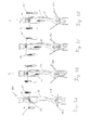
- a bending angle sensor 100 that includes a housing 10 having an upper end 10a and a lower end 10b.
- the lower end 10b is tapered towards the end and designed to be placed on a workpiece 200 or introduced into a bend or buckling of a workpiece 200, so that the bending angle can be measured.
- the workpiece 200 is not bent.
- the sliding block 12 is also pivotable, namely about an axis which is perpendicular to the longitudinal axis L of the angle sensor.
- a lower boundary 14 is mounted in the housing, here in the form of a bulge, which tapers conically upwards.
- FIG. 1A For example, a situation is shown in which a touch plate 20 is being inserted into the housing 10.
- the sliding block 12 is slightly pivoted so that its projection 12a is offset from the longitudinal axis L of the bending angle sensor 100. As can be seen, this facilitates the insertion of the touch disk 20.
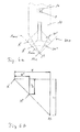
- FIG. 2 is there a sectional view of the bending angle sensor 100 of Figures 1A and 1B shown, but here additional elements of the angle sensor 100 are visible.
- a light source such as an LED, which emits a directed light beam, which is indicated here by a dotted line.
- an optical aid for example a prism, may be present.
- the light beam strikes a laterally disposed position detector 16, which in the illustrated embodiment is shown outside the housing 10 for clarity of illustration. In fact, however, the position detector 16 is received within the housing 10, being disposed substantially parallel to the recess 11.
- FIGS. 3A to 3D show a further embodiment of a bending angle sensor 100 according to the invention, which differs from that of FIG. 2 differs in that here two lateral optical position detectors 16, 16 'are provided, which are arranged on both sides of the recess 11 of the housing 10 parallel to this in the housing 10 (for clarity of illustration, the position detectors 16, 16' in the figure outside of the housing 10).
- FIG. 3A is the bending angle sensor 100 in its rest position, in which the lower end 10b of the housing 10 is placed on an unbent workpiece 200.
- the sliding block 12 is located next to the light source 15 and a beam splitter (not shown), which divides the emitted from the light source 15 beams into two sub-beams (indicated by dotted lines), which extend in opposite directions to each other. A first partial beam thus impinges on the position detector 16 and a second partial beam on the position detector 16 '.
- the pivotability of the sliding block 12 about the axis perpendicular to the longitudinal axis L of the angle sensor performs a dual function: first, it facilitates, as already described, the insertion of the touch plate 20 in the housing 10 and on the other hand, it allows the detection of a tilting of the workpiece 200th whose bending angle is to be measured.
- the tilt is to be measured, so an additional sensor must be used, which determines the tilt, for example, a magnetic Hall sensor, since in that embodiment, only one optical position detector 16 is present.
- the two probe disks 20 ', 20' ' move differently in the Z direction, so that a relative position to each other can be measured.
- the embodiment shown here is similar to that of FIG. 4 formed, but on the housing 10, a cap 17 is applied, which contains a receptacle for a rechargeable battery or a battery.
- a thus formed angle sensor 100 can be used in manual mode and operates independently of a power supply via a cable.
- angles at hidden ends of a workpiece can also be measured.
- the article 17 can also for receiving an electronic unit for the evaluation of measurement results be designed and include a display to make visible the measurement results.
- the attachment 17 may also be formed integrally with the housing 10.
- the measuring signals can also be passed on to external electronics, for example by wireless transmission.
- FIG. 6a shows in sectional view the bending angle sensor of FIG. 4
- a tip 10c of the housing 10 is placed on the center of a bend of the workpiece 200.
- the two sensing discs 20 ', 20 "move differently with respect to their magnitudes the respective displacements are detected with optical position detectors, wherein here an optical position detector 16 is shown, which may have a size of 4 mm ⁇ 4 mm, for example. which is reflected by one of the Tastusionn.
- an error that arises during the absolute measurement can also be detected with a relative measurement, wherein subsequently a correction value is stored, which can be used for future absolute measurements.
- a correction value is stored, which can be used for future absolute measurements.
Landscapes
- Physics & Mathematics (AREA)
- General Physics & Mathematics (AREA)
- Engineering & Computer Science (AREA)
- Mechanical Engineering (AREA)
- Length Measuring Devices With Unspecified Measuring Means (AREA)
- A Measuring Device Byusing Mechanical Method (AREA)
Priority Applications (3)
| Application Number | Priority Date | Filing Date | Title |
|---|---|---|---|
| EP13179482.8A EP2662159B1 (fr) | 2011-05-30 | 2011-05-30 | Disposif pour mesurer un angle de piliage |
| EP20110168102 EP2529850B1 (fr) | 2011-05-30 | 2011-05-30 | Capteur d'angle de pliage et procédé de mesure d'un angle de pliage |
| PCT/EP2012/060062 WO2012163921A1 (fr) | 2011-05-30 | 2012-05-29 | Capteur d'angle de pliage |
Applications Claiming Priority (1)
| Application Number | Priority Date | Filing Date | Title |
|---|---|---|---|
| EP20110168102 EP2529850B1 (fr) | 2011-05-30 | 2011-05-30 | Capteur d'angle de pliage et procédé de mesure d'un angle de pliage |
Related Child Applications (2)
| Application Number | Title | Priority Date | Filing Date |
|---|---|---|---|
| EP13179482.8A Division EP2662159B1 (fr) | 2011-05-30 | 2011-05-30 | Disposif pour mesurer un angle de piliage |
| EP13179482.8 Division-Into | 2013-08-06 |
Publications (2)
| Publication Number | Publication Date |
|---|---|
| EP2529850A1 true EP2529850A1 (fr) | 2012-12-05 |
| EP2529850B1 EP2529850B1 (fr) | 2013-09-11 |
Family
ID=44513372
Family Applications (2)
| Application Number | Title | Priority Date | Filing Date |
|---|---|---|---|
| EP20110168102 Active EP2529850B1 (fr) | 2011-05-30 | 2011-05-30 | Capteur d'angle de pliage et procédé de mesure d'un angle de pliage |
| EP13179482.8A Active EP2662159B1 (fr) | 2011-05-30 | 2011-05-30 | Disposif pour mesurer un angle de piliage |
Family Applications After (1)
| Application Number | Title | Priority Date | Filing Date |
|---|---|---|---|
| EP13179482.8A Active EP2662159B1 (fr) | 2011-05-30 | 2011-05-30 | Disposif pour mesurer un angle de piliage |
Country Status (2)
| Country | Link |
|---|---|
| EP (2) | EP2529850B1 (fr) |
| WO (1) | WO2012163921A1 (fr) |
Cited By (3)
| Publication number | Priority date | Publication date | Assignee | Title |
|---|---|---|---|---|
| CN104457487A (zh) * | 2014-12-15 | 2015-03-25 | 重庆市渝坝汽车配件有限公司 | 一种钣金件并排检测机构 |
| WO2015188213A1 (fr) | 2014-06-12 | 2015-12-17 | Trumpf Maschinen Austria Gmbh & Co. Kg. | Outil d'étalonnage d'un outil de mesure d'angle dans un poinçon de pliage et procédé d'étalonnage de l'outil de mesure d'angle |
| AT516260A4 (de) * | 2014-12-17 | 2016-04-15 | Trumpf Maschinen Austria Gmbh | Biegewerkzeug mit einer Längsversatz-Messvorrichtung |
Families Citing this family (1)
| Publication number | Priority date | Publication date | Assignee | Title |
|---|---|---|---|---|
| FR3019070B1 (fr) * | 2014-03-25 | 2016-04-01 | Pinette Emidecau Ind Pei | Procede et dispositif de pliage de toles |
Citations (3)
| Publication number | Priority date | Publication date | Assignee | Title |
|---|---|---|---|---|
| DE3008701A1 (de) | 1980-03-07 | 1981-09-24 | Johann 7057 Leutenbach Hess | Winkelmessvorrichtung fuer abkantpressen |
| EP1136146A1 (fr) | 2000-03-20 | 2001-09-26 | Trumpf GmbH & Co | Méthode de pliage des tôles et machine pour la mise en oeuvre de cette méthode |
| DE60029288T2 (de) | 1999-10-07 | 2007-07-19 | Murata Kikai K.K. | Biegevorrichtung und deren Betriebsverfahren |
-
2011
- 2011-05-30 EP EP20110168102 patent/EP2529850B1/fr active Active
- 2011-05-30 EP EP13179482.8A patent/EP2662159B1/fr active Active
-
2012
- 2012-05-29 WO PCT/EP2012/060062 patent/WO2012163921A1/fr active Application Filing
Patent Citations (3)
| Publication number | Priority date | Publication date | Assignee | Title |
|---|---|---|---|---|
| DE3008701A1 (de) | 1980-03-07 | 1981-09-24 | Johann 7057 Leutenbach Hess | Winkelmessvorrichtung fuer abkantpressen |
| DE60029288T2 (de) | 1999-10-07 | 2007-07-19 | Murata Kikai K.K. | Biegevorrichtung und deren Betriebsverfahren |
| EP1136146A1 (fr) | 2000-03-20 | 2001-09-26 | Trumpf GmbH & Co | Méthode de pliage des tôles et machine pour la mise en oeuvre de cette méthode |
Cited By (6)
| Publication number | Priority date | Publication date | Assignee | Title |
|---|---|---|---|---|
| WO2015188213A1 (fr) | 2014-06-12 | 2015-12-17 | Trumpf Maschinen Austria Gmbh & Co. Kg. | Outil d'étalonnage d'un outil de mesure d'angle dans un poinçon de pliage et procédé d'étalonnage de l'outil de mesure d'angle |
| CN104457487A (zh) * | 2014-12-15 | 2015-03-25 | 重庆市渝坝汽车配件有限公司 | 一种钣金件并排检测机构 |
| CN104457487B (zh) * | 2014-12-15 | 2016-12-07 | 重庆市渝坝汽车配件有限公司 | 一种钣金件并排检测机构 |
| AT516260A4 (de) * | 2014-12-17 | 2016-04-15 | Trumpf Maschinen Austria Gmbh | Biegewerkzeug mit einer Längsversatz-Messvorrichtung |
| AT516260B1 (de) * | 2014-12-17 | 2016-04-15 | Trumpf Maschinen Austria Gmbh | Biegewerkzeug mit einer Längsversatz-Messvorrichtung |
| US10464114B2 (en) | 2014-12-17 | 2019-11-05 | Trumpf Maschinen Austria Gmbh & Co. Kg. | Bending tool having a longitudinal-offset measuring device |
Also Published As
| Publication number | Publication date |
|---|---|
| EP2529850B1 (fr) | 2013-09-11 |
| EP2662159B1 (fr) | 2014-07-09 |
| WO2012163921A1 (fr) | 2012-12-06 |
| EP2662159A1 (fr) | 2013-11-13 |
Similar Documents
| Publication | Publication Date | Title |
|---|---|---|
| EP2328724B1 (fr) | Outil d'étalonnage, système et procédé d'étalonnage et d'alignement automatiques d'un dispositif de manipulation | |
| DE102008010916A1 (de) | Verfahren und Vorrichtung zur Ermittlung einer Ausrichtung von zwei drehbar gelagerten Maschinenteilen, einer Ausrichtung von zwei hohlzylinderförmigen Maschinenteilen oder zur Prüfung einer Komponente auf Geradheit entlang einer Längsseite | |
| EP0266713B1 (fr) | Dispositif pour mesurer des distances à partir d'une pièce d'oeuvre et pied à coulisse pourvu de mesure digitale de ces distances | |
| DE102016012536B4 (de) | Prüfmaschine und Werkzeug hierfür | |
| AT518993B1 (de) | Verfahren zum Betrieb einer Biegemaschine | |
| DE202010006391U1 (de) | Winkelmessvorrichtung für Abkantpressen | |
| EP2529850B1 (fr) | Capteur d'angle de pliage et procédé de mesure d'un angle de pliage | |
| WO2004052591A1 (fr) | Dispositif porte-outil et procédé pour positionner un outil | |
| EP1071921A1 (fr) | Procede et dispositif de mesure de la structure d'un objet | |
| AT511358B1 (de) | Vorrichtung zum biegen von blechen | |
| EP3207333A1 (fr) | Procédé de mesure d'angle de cintrage | |
| EP1462757A1 (fr) | Dispositif pour l'évaluation de la position spatiale d'un chariot coulissant le long d'un axe de coordonnées | |
| WO2005010457A2 (fr) | Dispositif de mesure de rugosite comportant un etalon | |
| DE102014110801B4 (de) | Verfahren zur Ausrichtung eines an einem Koordinatenmessgerät angeordneten Rauheitssensors sowie Koordinatenmessgerät zur Durchführung des Verfahrens | |
| DE102019135732B4 (de) | Vorrichtung zur Messung einer Längenänderung | |
| WO2004076968A1 (fr) | Procede de controle qualite de codes de matrix-codes bidimensionnels sur des pieces metalliques a usiner a l'aide d'un appareil de traitement d'images | |
| DE102010006382B4 (de) | Verfahren und Anordnung zum Betreiben von Koordinatenmessgeräten | |
| DE29704636U1 (de) | Temperaturunempfindlicher Taststift und temperaturunempfindliche Taststiftverlängerung sowie temperaturunempfindliche Tasterverlängerung für den Tastkopf eines Koordinatenmeßgerätes | |
| DE3016782A1 (de) | Sonde zur messung von werkstuecken | |
| DE10319947B4 (de) | Einrichtung zur Messung der Umfangsgestalt rotationssymmetrischer Werkstücke | |
| DE102008063236B4 (de) | Verfahren zum Kalibrieren einer Messkraft an einem Koordinatenmessgerät | |
| EP2983842B1 (fr) | Presse plieuse avec un dispositif de mesure d'angle de pliage | |
| DE102012104017A1 (de) | Messeinrichtung und Verfahren zur Messung von Kugeln | |
| DE102008024806A1 (de) | Verfahren zum Justieren einer Profilbearbeitungsmaschine für die Bearbeitung von Holz oder Holzersatzwerkstoffen im Durchlaufverfahren und Justiersystem | |
| DE102019126976A1 (de) | Taster eines Kontur- und/oder Rauheitsmessgeräts |
Legal Events
| Date | Code | Title | Description |
|---|---|---|---|
| PUAI | Public reference made under article 153(3) epc to a published international application that has entered the european phase |
Free format text: ORIGINAL CODE: 0009012 |
|
| AK | Designated contracting states |
Kind code of ref document: A1 Designated state(s): AL AT BE BG CH CY CZ DE DK EE ES FI FR GB GR HR HU IE IS IT LI LT LU LV MC MK MT NL NO PL PT RO RS SE SI SK SM TR |
|
| AX | Request for extension of the european patent |
Extension state: BA ME |
|
| 17P | Request for examination filed |
Effective date: 20130226 |
|
| GRAP | Despatch of communication of intention to grant a patent |
Free format text: ORIGINAL CODE: EPIDOSNIGR1 |
|
| INTG | Intention to grant announced |
Effective date: 20130503 |
|
| GRAS | Grant fee paid |
Free format text: ORIGINAL CODE: EPIDOSNIGR3 |
|
| GRAA | (expected) grant |
Free format text: ORIGINAL CODE: 0009210 |
|
| AK | Designated contracting states |
Kind code of ref document: B1 Designated state(s): AL AT BE BG CH CY CZ DE DK EE ES FI FR GB GR HR HU IE IS IT LI LT LU LV MC MK MT NL NO PL PT RO RS SE SI SK SM TR |
|
| REG | Reference to a national code |
Ref country code: GB Ref legal event code: FG4D Free format text: NOT ENGLISH |
|
| REG | Reference to a national code |
Ref country code: CH Ref legal event code: EP |
|
| REG | Reference to a national code |
Ref country code: AT Ref legal event code: REF Ref document number: 631325 Country of ref document: AT Kind code of ref document: T Effective date: 20130915 |
|
| REG | Reference to a national code |
Ref country code: IE Ref legal event code: FG4D Free format text: LANGUAGE OF EP DOCUMENT: GERMAN |
|
| REG | Reference to a national code |
Ref country code: DE Ref legal event code: R096 Ref document number: 502011001311 Country of ref document: DE Effective date: 20131107 |
|
| PG25 | Lapsed in a contracting state [announced via postgrant information from national office to epo] |
Ref country code: HR Free format text: LAPSE BECAUSE OF FAILURE TO SUBMIT A TRANSLATION OF THE DESCRIPTION OR TO PAY THE FEE WITHIN THE PRESCRIBED TIME-LIMIT Effective date: 20130911 Ref country code: NO Free format text: LAPSE BECAUSE OF FAILURE TO SUBMIT A TRANSLATION OF THE DESCRIPTION OR TO PAY THE FEE WITHIN THE PRESCRIBED TIME-LIMIT Effective date: 20131211 Ref country code: SE Free format text: LAPSE BECAUSE OF FAILURE TO SUBMIT A TRANSLATION OF THE DESCRIPTION OR TO PAY THE FEE WITHIN THE PRESCRIBED TIME-LIMIT Effective date: 20130911 Ref country code: LT Free format text: LAPSE BECAUSE OF FAILURE TO SUBMIT A TRANSLATION OF THE DESCRIPTION OR TO PAY THE FEE WITHIN THE PRESCRIBED TIME-LIMIT Effective date: 20130911 Ref country code: CY Free format text: LAPSE BECAUSE OF FAILURE TO SUBMIT A TRANSLATION OF THE DESCRIPTION OR TO PAY THE FEE WITHIN THE PRESCRIBED TIME-LIMIT Effective date: 20130918 |
|
| REG | Reference to a national code |
Ref country code: NL Ref legal event code: VDEP Effective date: 20130911 |
|
| REG | Reference to a national code |
Ref country code: LT Ref legal event code: MG4D |
|
| PG25 | Lapsed in a contracting state [announced via postgrant information from national office to epo] |
Ref country code: FI Free format text: LAPSE BECAUSE OF FAILURE TO SUBMIT A TRANSLATION OF THE DESCRIPTION OR TO PAY THE FEE WITHIN THE PRESCRIBED TIME-LIMIT Effective date: 20130911 Ref country code: GR Free format text: LAPSE BECAUSE OF FAILURE TO SUBMIT A TRANSLATION OF THE DESCRIPTION OR TO PAY THE FEE WITHIN THE PRESCRIBED TIME-LIMIT Effective date: 20131212 Ref country code: LV Free format text: LAPSE BECAUSE OF FAILURE TO SUBMIT A TRANSLATION OF THE DESCRIPTION OR TO PAY THE FEE WITHIN THE PRESCRIBED TIME-LIMIT Effective date: 20130911 |
|
| PG25 | Lapsed in a contracting state [announced via postgrant information from national office to epo] |
Ref country code: CY Free format text: LAPSE BECAUSE OF FAILURE TO SUBMIT A TRANSLATION OF THE DESCRIPTION OR TO PAY THE FEE WITHIN THE PRESCRIBED TIME-LIMIT Effective date: 20130911 |
|
| PG25 | Lapsed in a contracting state [announced via postgrant information from national office to epo] |
Ref country code: CZ Free format text: LAPSE BECAUSE OF FAILURE TO SUBMIT A TRANSLATION OF THE DESCRIPTION OR TO PAY THE FEE WITHIN THE PRESCRIBED TIME-LIMIT Effective date: 20130911 Ref country code: NL Free format text: LAPSE BECAUSE OF FAILURE TO SUBMIT A TRANSLATION OF THE DESCRIPTION OR TO PAY THE FEE WITHIN THE PRESCRIBED TIME-LIMIT Effective date: 20130911 Ref country code: IS Free format text: LAPSE BECAUSE OF FAILURE TO SUBMIT A TRANSLATION OF THE DESCRIPTION OR TO PAY THE FEE WITHIN THE PRESCRIBED TIME-LIMIT Effective date: 20140111 Ref country code: RO Free format text: LAPSE BECAUSE OF FAILURE TO SUBMIT A TRANSLATION OF THE DESCRIPTION OR TO PAY THE FEE WITHIN THE PRESCRIBED TIME-LIMIT Effective date: 20130911 Ref country code: EE Free format text: LAPSE BECAUSE OF FAILURE TO SUBMIT A TRANSLATION OF THE DESCRIPTION OR TO PAY THE FEE WITHIN THE PRESCRIBED TIME-LIMIT Effective date: 20130911 Ref country code: SK Free format text: LAPSE BECAUSE OF FAILURE TO SUBMIT A TRANSLATION OF THE DESCRIPTION OR TO PAY THE FEE WITHIN THE PRESCRIBED TIME-LIMIT Effective date: 20130911 |
|
| PG25 | Lapsed in a contracting state [announced via postgrant information from national office to epo] |
Ref country code: ES Free format text: LAPSE BECAUSE OF FAILURE TO SUBMIT A TRANSLATION OF THE DESCRIPTION OR TO PAY THE FEE WITHIN THE PRESCRIBED TIME-LIMIT Effective date: 20130911 Ref country code: PL Free format text: LAPSE BECAUSE OF FAILURE TO SUBMIT A TRANSLATION OF THE DESCRIPTION OR TO PAY THE FEE WITHIN THE PRESCRIBED TIME-LIMIT Effective date: 20130911 |
|
| REG | Reference to a national code |
Ref country code: DE Ref legal event code: R097 Ref document number: 502011001311 Country of ref document: DE |
|
| PG25 | Lapsed in a contracting state [announced via postgrant information from national office to epo] |
Ref country code: PT Free format text: LAPSE BECAUSE OF FAILURE TO SUBMIT A TRANSLATION OF THE DESCRIPTION OR TO PAY THE FEE WITHIN THE PRESCRIBED TIME-LIMIT Effective date: 20140113 |
|
| PLBE | No opposition filed within time limit |
Free format text: ORIGINAL CODE: 0009261 |
|
| STAA | Information on the status of an ep patent application or granted ep patent |
Free format text: STATUS: NO OPPOSITION FILED WITHIN TIME LIMIT |
|
| 26N | No opposition filed |
Effective date: 20140612 |
|
| REG | Reference to a national code |
Ref country code: DE Ref legal event code: R097 Ref document number: 502011001311 Country of ref document: DE Effective date: 20140612 |
|
| PG25 | Lapsed in a contracting state [announced via postgrant information from national office to epo] |
Ref country code: DK Free format text: LAPSE BECAUSE OF FAILURE TO SUBMIT A TRANSLATION OF THE DESCRIPTION OR TO PAY THE FEE WITHIN THE PRESCRIBED TIME-LIMIT Effective date: 20130911 |
|
| PG25 | Lapsed in a contracting state [announced via postgrant information from national office to epo] |
Ref country code: LU Free format text: LAPSE BECAUSE OF FAILURE TO SUBMIT A TRANSLATION OF THE DESCRIPTION OR TO PAY THE FEE WITHIN THE PRESCRIBED TIME-LIMIT Effective date: 20140530 |
|
| REG | Reference to a national code |
Ref country code: CH Ref legal event code: PL |
|
| PG25 | Lapsed in a contracting state [announced via postgrant information from national office to epo] |
Ref country code: MC Free format text: LAPSE BECAUSE OF FAILURE TO SUBMIT A TRANSLATION OF THE DESCRIPTION OR TO PAY THE FEE WITHIN THE PRESCRIBED TIME-LIMIT Effective date: 20130911 Ref country code: CH Free format text: LAPSE BECAUSE OF NON-PAYMENT OF DUE FEES Effective date: 20140531 Ref country code: LI Free format text: LAPSE BECAUSE OF NON-PAYMENT OF DUE FEES Effective date: 20140531 |
|
| REG | Reference to a national code |
Ref country code: IE Ref legal event code: MM4A |
|
| PG25 | Lapsed in a contracting state [announced via postgrant information from national office to epo] |
Ref country code: IE Free format text: LAPSE BECAUSE OF NON-PAYMENT OF DUE FEES Effective date: 20140530 |
|
| GBPC | Gb: european patent ceased through non-payment of renewal fee |
Effective date: 20150530 |
|
| PG25 | Lapsed in a contracting state [announced via postgrant information from national office to epo] |
Ref country code: MT Free format text: LAPSE BECAUSE OF FAILURE TO SUBMIT A TRANSLATION OF THE DESCRIPTION OR TO PAY THE FEE WITHIN THE PRESCRIBED TIME-LIMIT Effective date: 20130911 |
|
| PG25 | Lapsed in a contracting state [announced via postgrant information from national office to epo] |
Ref country code: SM Free format text: LAPSE BECAUSE OF FAILURE TO SUBMIT A TRANSLATION OF THE DESCRIPTION OR TO PAY THE FEE WITHIN THE PRESCRIBED TIME-LIMIT Effective date: 20130911 Ref country code: GB Free format text: LAPSE BECAUSE OF NON-PAYMENT OF DUE FEES Effective date: 20150530 |
|
| REG | Reference to a national code |
Ref country code: FR Ref legal event code: PLFP Year of fee payment: 6 |
|
| PG25 | Lapsed in a contracting state [announced via postgrant information from national office to epo] |
Ref country code: RS Free format text: LAPSE BECAUSE OF NON-PAYMENT OF DUE FEES Effective date: 20130911 Ref country code: BG Free format text: LAPSE BECAUSE OF FAILURE TO SUBMIT A TRANSLATION OF THE DESCRIPTION OR TO PAY THE FEE WITHIN THE PRESCRIBED TIME-LIMIT Effective date: 20130911 |
|
| PG25 | Lapsed in a contracting state [announced via postgrant information from national office to epo] |
Ref country code: BE Free format text: LAPSE BECAUSE OF FAILURE TO SUBMIT A TRANSLATION OF THE DESCRIPTION OR TO PAY THE FEE WITHIN THE PRESCRIBED TIME-LIMIT Effective date: 20140531 Ref country code: SI Free format text: LAPSE BECAUSE OF FAILURE TO SUBMIT A TRANSLATION OF THE DESCRIPTION OR TO PAY THE FEE WITHIN THE PRESCRIBED TIME-LIMIT Effective date: 20130911 Ref country code: HU Free format text: LAPSE BECAUSE OF FAILURE TO SUBMIT A TRANSLATION OF THE DESCRIPTION OR TO PAY THE FEE WITHIN THE PRESCRIBED TIME-LIMIT; INVALID AB INITIO Effective date: 20110530 Ref country code: TR Free format text: LAPSE BECAUSE OF FAILURE TO SUBMIT A TRANSLATION OF THE DESCRIPTION OR TO PAY THE FEE WITHIN THE PRESCRIBED TIME-LIMIT Effective date: 20130911 |
|
| REG | Reference to a national code |
Ref country code: FR Ref legal event code: PLFP Year of fee payment: 7 |
|
| REG | Reference to a national code |
Ref country code: FR Ref legal event code: PLFP Year of fee payment: 8 |
|
| PG25 | Lapsed in a contracting state [announced via postgrant information from national office to epo] |
Ref country code: MK Free format text: LAPSE BECAUSE OF FAILURE TO SUBMIT A TRANSLATION OF THE DESCRIPTION OR TO PAY THE FEE WITHIN THE PRESCRIBED TIME-LIMIT Effective date: 20130911 |
|
| PG25 | Lapsed in a contracting state [announced via postgrant information from national office to epo] |
Ref country code: AL Free format text: LAPSE BECAUSE OF FAILURE TO SUBMIT A TRANSLATION OF THE DESCRIPTION OR TO PAY THE FEE WITHIN THE PRESCRIBED TIME-LIMIT Effective date: 20130911 |
|
| PGFP | Annual fee paid to national office [announced via postgrant information from national office to epo] |
Ref country code: IT Payment date: 20230526 Year of fee payment: 13 |
|
| PGFP | Annual fee paid to national office [announced via postgrant information from national office to epo] |
Ref country code: DE Payment date: 20240521 Year of fee payment: 14 |
|
| PGFP | Annual fee paid to national office [announced via postgrant information from national office to epo] |
Ref country code: AT Payment date: 20240522 Year of fee payment: 14 |
|
| PGFP | Annual fee paid to national office [announced via postgrant information from national office to epo] |
Ref country code: FR Payment date: 20240528 Year of fee payment: 14 |