EP2528080A1 - Elektromagnetisches Relais - Google Patents
Elektromagnetisches Relais Download PDFInfo
- Publication number
- EP2528080A1 EP2528080A1 EP12168480A EP12168480A EP2528080A1 EP 2528080 A1 EP2528080 A1 EP 2528080A1 EP 12168480 A EP12168480 A EP 12168480A EP 12168480 A EP12168480 A EP 12168480A EP 2528080 A1 EP2528080 A1 EP 2528080A1
- Authority
- EP
- European Patent Office
- Prior art keywords
- shaft
- diameter
- base
- card
- armature
- Prior art date
- Legal status (The legal status is an assumption and is not a legal conclusion. Google has not performed a legal analysis and makes no representation as to the accuracy of the status listed.)
- Granted
Links
Images


Classifications
-
- H—ELECTRICITY
- H01—ELECTRIC ELEMENTS
- H01H—ELECTRIC SWITCHES; RELAYS; SELECTORS; EMERGENCY PROTECTIVE DEVICES
- H01H50/00—Details of electromagnetic relays
- H01H50/54—Contact arrangements
- H01H50/56—Contact spring sets
- H01H50/58—Driving arrangements structurally associated therewith; Mounting of driving arrangements on armature
-
- H—ELECTRICITY
- H01—ELECTRIC ELEMENTS
- H01H—ELECTRIC SWITCHES; RELAYS; SELECTORS; EMERGENCY PROTECTIVE DEVICES
- H01H50/00—Details of electromagnetic relays
- H01H50/02—Bases; Casings; Covers
- H01H50/04—Mounting complete relay or separate parts of relay on a base or inside a case
- H01H50/041—Details concerning assembly of relays
- H01H50/042—Different parts are assembled by insertion without extra mounting facilities like screws, in an isolated mounting part, e.g. stack mounting on a coil-support
-
- H—ELECTRICITY
- H01—ELECTRIC ELEMENTS
- H01H—ELECTRIC SWITCHES; RELAYS; SELECTORS; EMERGENCY PROTECTIVE DEVICES
- H01H50/00—Details of electromagnetic relays
- H01H50/16—Magnetic circuit arrangements
- H01H50/18—Movable parts of magnetic circuits, e.g. armature
- H01H50/24—Parts rotatable or rockable outside coil
- H01H50/26—Parts movable about a knife edge
Definitions
- the present invention relates to an electromagnetic relay.
- Patent Literature 1 Japanese Patent Laid-Open Publication No. 2005-293952 (hereinafter, referred to as Patent Literature 1), an electromagnetic relay has been known, which includes: an armature reciprocated by excitation and non-excitation of an electromagnet block; a card swinging with movement of the armature; and a contact unit switched on and off according to the swing of the card.
- the card includes a shaft portion at an end thereof which is swingably attached to a base by causing the shaft portion to be fit and supported onto the base.
- the shaft portion of the card therefore could drop out of the bearing recess during assembly of the electromagnetic relay. Such detachment of the card from the base degrades the smooth assembly operation.
- An object of the present invention is to provide an electromagnetic relay with the assembly operation further improved.
- a first feature of the present invention is summarized to be an electromagnetic relay including: an electromagnet block mounted on a base; an armature reciprocated by excitation and non-excitation of the electromagnet block; a card swingably attached to the base through a pivot shaft and configured to swing with movement of the armature; and a contact unit switched on and off according to the swing of the card, wherein the pivot shaft includes at least one shaft portion rotatably engaged with the base and at least one large-diameter portion having a larger diameter than that of the at least one shaft portion, the base includes: at least one shaft bearing portion which is opened at the surface side of the base and is configured to receive the at least one shaft portion; and at least one large-diameter bearing portion configured to receive the at least one large-diameter portion, and opening width of the at least one shaft bearing portion is smaller than the diameter of the at least one shaft portion at an insertion port side through which the at least one shaft bearing portion receives the at least one shaft portion, while at an internal side of the base, the at
- a second feature of the present invention is summarized in that the at least one large-diameter portion is provided adjacent to the at least one shaft portion in an axial direction of a central axis of the at least one shaft portion.
- a third feature of the present invention is summarized in that the at least one shaft portion are arranged at both ends of the pivot shaft in the axial direction of the central axis thereof, and the at least one large-diameter portion is provided at the center of the pivot shaft in the axial direction of the central axis thereof.
- An electromagnetic relay 1 includes a base 2, an electromagnet block 3, an armature 4, a card 5, a contact unit 6, and a case 7.
- the base 2 is made of synthetic resin which is an insulating material and has a substantially rectangular shape with its overall planer shape having a longitudinal direction and a transverse direction and has a certain thickness.
- the electromagnet block 3 is mounted on an end of the base 2 in the longitudinal direction and includes: a bobbin 32 with a coil 31 wound thereon; an iron core 33; and a substantially L-shaped yoke 34 connected to a lower end of the iron core 33.
- a pair of coil terminals 31a arranged in the transverse direction of the base 2 are protruded downward from the base 2. Portions of the yoke 34 stood from the base 2 sandwich a permanent magnet 35.
- the armature 4 is made of a soft magnetic material and has a bent portion 4a to form a substantially L-shape.
- An end portion of the armature 4 forms a horizontal portion 4b facing the upper surface of the bobbin 32, and the other end portion thereof forms a vertical portion 4c extending along a side surface of the yoke 34 opposite to the bobbin 32.
- the armature 4 is arranged so that the bent portion 4a is supported on the upper end of the yoke 34 while the top of the horizontal portion 4b faces the upper end surface of the iron core 33 with a proper distance therebetween.
- the armature 4 is held at that position (a position in which the vertical portion 4c of the armature 4 is rotated counterclockwise in Fig. 1 about the bent portion 4a as a fulcrum so as to be shifted in a direction away from the yoke 34) by attraction of the permanent magnet 35.
- the armature 4 is provided with a hinge spring 41, which prevents the armature 4 from being displaced by reciprocation.
- the electromagnetic relay 1 is a so-called latch type in which the armature 4 is reciprocated by changing the direction of the current applied to the coil 31.
- the card 5 is placed between the vertical portion 4c of the armature 4 and the contact unit 6 provided at the other end of the base 2 in the longitudinal direction and is swingably attached to the base 2 through a pivot shaft 51 provided at its lower end.
- the direction of swing at this time is in the longitudinal direction of the base 2 as indicated by arrow b of Fig. 1 .
- first protrusion 52 is provided substantially at the middle of the card 5 in the vertical direction and is configured to come into contact with the vertical portion 4c of the armature 4.
- second protrusion 53 is located above the first protrusion 52.
- the contact unit 6 includes: a fixed terminal 61 having a fixed contact unit 61a; and a movable spring 62 having a movable contact unit 62a.
- the fixed terminal 61 and movable spring 62 are located such that the movable spring 62 is located at the card 5 side whereas the fixed terminal 61 is located at the side away from the card 5 respectively, and face each other in the longitudinal direction of the base 2 so as to stand from the base 2 with the respective lower ends supported by the base 2.
- the fixed terminal 61 and movable spring 62 have terminals 61b and 62b protruded downward from the base 2.
- the contact unit 6 is configured to serve as a contact in which the fixed contact unit 61a and movable contact unit 62a are separated from each other when the horizontal portion 4b is not attracted by the iron core 33 and come into contact with each other if the electromagnet block 3 is excited so that the horizontal portion 4b is attracted by the iron core 33.
- the movable spring 62 is positioned in contact with or is close to the second protrusion 53 of the card 5 when the horizontal portion 4b is not attracted by the iron core 33.
- the second protrusion 53 presses the movable spring 62, which is then bent.
- the movable spring 62 bends, the movable contact unit 62a comes into contact with the fixed contact unit 61a, turning on the contact unit 6.
- the contact unit 6 is switched on and off according to the swing of the card 5.
- the contact unit 6 may have such a structure that the contact unit 6 is on when the horizontal portion 4b is not attracted by the iron core 33 or may have a contact structure including both of a contact which is on while the horizontal portion 4b is not attracted by the iron core 33 and a contact which is off while the horizontal portion 4b is not attracted by the iron core 33.
- the lower end of the contact unit 6 is supported on the base 2 on which the electromagnet block 3 is mounted.
- the base 2 is made of an insulating material and thus can increase the electrical insulation between the coil 31 and the contact unit 6.
- the case 7 has a rectangular solid housing form opened downward as a whole.
- a bottom opening 7a is configured to fit into substantially close contact with a step portion 2a formed in the periphery of the base 2.
- a partition wall 71 to be positioned between the vertical portion 4c of the armature 4 and the card 5 is provided inside the case 7.
- the partition wall 71 includes a cutout portion 71a allowing the first protrusion 52 to penetrate the partition wall 71.
- the partition wall 71 thus has a gate shape.
- an engagement hole 72 is located substantially at the center in the longitudinal direction.
- the engagement holes 72 are engaged with engagement protrusions 21 protruding from the step portion 2a of the base 2 to prevent the case 7 from being detached.
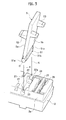
- the pivot shaft 51 of the card 5 includes shaft portions 51a rotatably engaged with the base 2 and a large-diameter portion 51b provided adjacent thereto in the axial direction of a central axis C of the shaft portion 51a .
- the large-diameter portion 51b is wider than the shaft portions 51a.
- the shaft portions 51a are provided at both ends of the pivot shaft 51 in the axial direction of the central axis C, and the large-diameter portion 51b is provided between the shaft portions 51a (at the center of the pivot shaft 51 in the axial direction of the central axis C) .
- Figs. 6(a) and 7 (a) schematically show only the pivot shaft 51 for explanation.
- a pair of shaft bearing portions 22 configured to receive the shaft portions 51a are formed so that the shaft portions 51a rotate inside the base 2.
- the pair of shaft bearing portions 22 are provided at the positions corresponding to the shaft portions 51a provided at both ends of the pivot shaft 51 in the axial direction of the central axis C.
- a large-diameter bearing portion 23 receiving the large-diameter portion 51b of the pivot shaft 51 is formed.
- Figs. 6(b) and 7 (b) schematically show only the shaft bearing portions 22 and large-diameter bearing portion 23 for explanation.
- the outer ends of the shaft bearing portions 22 in the axial direction of the central axis C may also be closed.
- the shaft bearing portions 22 and the large-diameter bearing portion 23 are opened to the surface side (the top surface side in Fig. 1 ) of the base 2 to receive the pivot shaft 51 perpendicularly from above the surface side of the base 2.
- the opening portion of each shaft bearing portion 22 is an insertion port 22a through which one of the shaft portions 51a is accepted.
- the surface side (the top surface side in Fig. 1 ) of the base 2 is the near side in the direction of insertion of the card 5.
- the pivot shaft 51 is pressed from above into the shaft bearing portions 22 and large-diameter bearing portion 23.
- the shaft portions 51a are fit into the shaft bearing portions 22, and the large-diameter portion 51b is fit into the large-diameter bearing 23.
- the card 5 is thus attached to the base 2 so as to freely swing in a direction b.
- an opening width a1 of each shaft bearing portion 22 on the insertion portion 22a side is made smaller than a diameter A1 of the shaft portion 51a (a ⁇ A1).
- a diameter a2 of the shaft bearing portion 22 on the internal side of the base 2 is made larger than the diameter A1 of the shaft portion 51a and smaller than a width A2 of the large-diameter portion 51b (A1 ⁇ a2 ⁇ A2).
- a width a3 of the large-diameter bearing 23 only needs to be larger than the width A2 of the large-diameter portion 51b (a3 > A2).
- the opening width a1 of the insertion port 22a is made smaller than the diameter A1 of the shaft portion 51a, to cause the shaft portions 51a of the pivot shaft 51 to fit into (to be received by) the shaft bearing portions 22, the shaft portions 51a are press-fit to the shaft bearing portions 22. Accordingly, it is preferable that the difference (A1-a1) between the diameter A1 of the shaft portions 51a and the opening width a1 is set so as to allow for press fitting of the shaft portions 51a.
- the shaft portions 51a By press fitting of the shaft portions 51a into the shaft bearing portions 22 in such a manner, the shaft portions 51a can be prevented from dropping out of the shaft bearing portions 22 by external impact.
- the card 5 can be therefore prevented from being easily detached from the base 2.
- the shaft portions 51a and large-diameter portion 51b of the pivot shaft 51 are concentrically formed to have circular cross-sections, and the width A2 of the large-diameter portion 51b can be replaced with a diameter A2.
- the large-diameter portion 51b does not necessarily have a circular cross-section.
- the large-diameter portion 51b needs to be configured such that the width A2 of the large diameter portion 51b is larger than the diameter A1 of the shaft portions 51a and each end face 51c of the large-diameter portion 51b in the axial direction of the central axis C abuts a step surface 24 between one of the shaft bearing portions 22 and the large-diameter bearing portion 23.
- Reference numeral 25 in Figs. 3 and 4 indicates a support recess in which the bottom of the movable spring 62 is inserted.
- Reference numeral 26 indicates a support recess in which the bottom of the fixed terminal 61 is inserted.
- Reference numeral 27 indicates support notches into which the both side portions of the cutout portion 71a of the partition wall 71 of the case 7 are fit.
- Such a structure allows the electromagnetic relay 1 to operate as follows.
- the armature 4 is positioned with the vertical portion 4c shifted to the yoke 34 side.
- the card 5 is swung and located on the armature 4 side by spring force of the movable spring 62, and the contact unit 6 is turned off with the fixed contact unit 61a being separated from the movable contact unit 62.
- the horizontal portion 4b of the armature 4 is attracted by the iron core 33 to cause the armature 4 to rotate counterclockwise in Fig. 1 around the bent portion 4a, and the vertical portion 4c causes the card 5 to swing toward the contact unit 6.
- the card 5 then bends the movable spring 62 toward the fixed terminal 61 against the spring force of the movable spring 62 to bring the movable contact unit 62a into contact with the fixed contact unit 61a for electrical conduction.
- the contact unit 6 is thus turned on.
- the card 5 swings around the pivot shaft 51 but substantially swings in such a manner that the shaft portions 51a of the pivot shaft 51 rotate relative to the shaft bearing portions 22 of the base 2.
- the card 5 since the card 5 operates with the shaft portion 51a as the fulcrum of swing, it becomes easy to ensure a stable swing operation.
- the pivot shaft 51 is provided with the large-diameter portion 51b adjacent to the shaft portions 51a on the central axis C. Accordingly, the large-diameter portion 51b can abut the step surfaces 24 between the shaft bearing portions 22 and the large-diameter bearing portion 23. This can prevent the card 5 from being shifted in the transverse direction of the base 2.
- the pivot shaft 51 which allows the card 5 to be swingably attached to the base 2 includes the shaft portions 51a and the large-diameter portion 51b having a diameter larger than that of the shaft portions 51a.
- the shaft portions 51a are configured to be received by the shaft bearing portions 22 of the base 2, and the large-diameter portion 51b is configured to be received by the large-diameter bearing portion 23.
- each shaft bearing portion 22 is configured such that the opening width a1 on the insertion port 22a side which is opened on the surface side of the base 2 is made smaller than the diameter A1 of the shaft portions 51a. This can prevent the shaft portions 51a received through the insertion ports 22a into the shaft bearing portions 22 from easily dropping out from the insertion ports 22a.
- the diameter (opening width) a2 of the shaft bearing portions 22 receiving the shaft portions 51a on the internal side of the base 2 is made larger than the diameter A1 of the shaft portions 51a. This allows for smooth rotation of the shaft portions 51a, that is, smooth swing of the card 5.
- the opening width of the shaft bearing portions 22 is made smaller than the width A2 of the large-diameter portion 51b, and the large-diameter portion 51b is provided adjacent to the shaft portions 51a in the axial direction of the central axis C.
- the end surfaces 51c of the large-diameter portion 51b can abut the step surface 24 thereby preventing the large-diameter portion 51b from entering the shaft bearing portions 22. This can further ensure positioning of the pivot shaft 51 in the axial direction and can reliably prevent the pivot shaft 51 from being shifted from the shaft bearing portions 22 in the axial direction of the central axis C, thus reliably preventing the card 5 from being detached from the base 2.
- the pivot shaft 51 can be prevented from easily dropping out of the shaft bearing portions 22. This can prevent the card 5 from being easily detached after the card 5 is assembled to the base 2 at the assembly of the electromagnetic relay 1, thus further improving the assembly operation of the electromagnetic relay.
- the shaft portions 51a are provided at both ends of the pivot shaft 51 in the axial direction of the central axis C, and the large-diameter portion 51b is provided between the shaft portions 51a provided at the both ends (at the center of the pivot shaft 51 in the axial direction of the central axis C) . It is therefore possible to increase the supporting span of the shaft portions 51a while preventing the width of the pivot shaft 51 from increasing. Thus, the pivot shaft 51 can be more stably attached to the base 2, thus allowing for more stable swing of the card 5.
- the pair of shaft portions 51a are provided at the both ends in the axial direction of the central axis C, and the large-diameter portion 51b is provided between the both shaft portions 51a.
- a shaft portion 51a is provided in the middle of the pivot shaft 51 in the axial direction of the central axis C, and a pair of large-diameter portions 51b are provided on both sides of the shaft portion 51a.
- Fig. 8(a) a shaft portion 51a is provided in the middle of the pivot shaft 51 in the axial direction of the central axis C, and a pair of large-diameter portions 51b are provided on both sides of the shaft portion 51a.
- the shaft bearing portion 22 is provided at the center corresponding to the shaft portion 51a, and the large-diameter bearing portions 23 are provided on both sides of the shaft baring portion 22 corresponding to the pair of large-diameter portions 51b.
- the opening width a1 at an insertion portion 22a side of the shaft bearing portion 22 which is provided at the center is made smaller than the diameter A1 of the shaft portion 51a.
- the opening width of the shaft bearing portion 22 on the internal side of the base 2 is made larger than the diameter A1 of the shaft portion 51a and is made smaller than the width A2 of the large-diameter portions 51b. This allows the shaft portion 51a to smoothly rotate and allows the pivot shaft 51 to be positioned in the axial direction.
- the aforementioned embodiments show a so-called latch type electromagnetic relay.
- the vertical portion of the armature may be configured to reciprocate in directions away from and toward the yoke by excitation and non-excitation of the electromagnetic block.
- the electromagnetic relay may be configured such that the horizontal portion of the armature is biased by a hinge spring in a direction away from the iron core and the vertical portion of the armature moves in a direction toward the yoke by the hinge spring when the electromagnet block is demagnetized.
Landscapes
- Physics & Mathematics (AREA)
- Electromagnetism (AREA)
- Electromagnets (AREA)
- Pivots And Pivotal Connections (AREA)
Applications Claiming Priority (1)
| Application Number | Priority Date | Filing Date | Title |
|---|---|---|---|
| JP2011116167A JP5903613B2 (ja) | 2011-05-24 | 2011-05-24 | 電磁リレー |
Publications (2)
| Publication Number | Publication Date |
|---|---|
| EP2528080A1 true EP2528080A1 (de) | 2012-11-28 |
| EP2528080B1 EP2528080B1 (de) | 2014-12-17 |
Family
ID=46062161
Family Applications (1)
| Application Number | Title | Priority Date | Filing Date |
|---|---|---|---|
| EP20120168480 Active EP2528080B1 (de) | 2011-05-24 | 2012-05-18 | Elektromagnetisches Relais |
Country Status (3)
| Country | Link |
|---|---|
| EP (1) | EP2528080B1 (de) |
| JP (1) | JP5903613B2 (de) |
| CN (1) | CN102800528B (de) |
Families Citing this family (4)
| Publication number | Priority date | Publication date | Assignee | Title |
|---|---|---|---|---|
| KR101529590B1 (ko) * | 2013-12-19 | 2015-06-29 | 엘에스산전 주식회사 | 배선용 차단기의 순시트립장치 |
| CN104616934A (zh) * | 2015-01-14 | 2015-05-13 | 宁波世通电子科技有限公司 | 一种灵敏小型继电器 |
| CN104795281B (zh) * | 2015-04-27 | 2017-10-03 | 国网湖北省电力公司咸宁供电公司 | 一种电磁继电器 |
| JP7149824B2 (ja) * | 2018-11-30 | 2022-10-07 | 富士通コンポーネント株式会社 | 電磁継電器 |
Citations (7)
| Publication number | Priority date | Publication date | Assignee | Title |
|---|---|---|---|---|
| GB614892A (en) * | 1945-09-07 | 1948-12-23 | Western Electric Co | Improvements in electromagnetic relays |
| JPH09320441A (ja) * | 1996-05-31 | 1997-12-12 | Omron Corp | 電磁継電器 |
| JP2002184291A (ja) * | 2000-12-11 | 2002-06-28 | Omron Corp | 電磁継電器 |
| EP1271593A2 (de) * | 2001-06-22 | 2003-01-02 | TYCO Electronics Austria GmbH | Relais |
| JP2005293952A (ja) | 2004-03-31 | 2005-10-20 | Omron Corp | 電磁継電器 |
| EP1852885A1 (de) * | 2006-05-06 | 2007-11-07 | TYCO Electronics Austria GmbH | Elektrisches Relais |
| US20080238591A1 (en) * | 2007-03-26 | 2008-10-02 | Fujitsu Component Limited | Electromagnetic relay |
Family Cites Families (4)
| Publication number | Priority date | Publication date | Assignee | Title |
|---|---|---|---|---|
| JPH045041U (de) * | 1990-04-24 | 1992-01-17 | ||
| JPH10255630A (ja) * | 1997-03-10 | 1998-09-25 | Omron Corp | 電磁継電器 |
| CN1949204A (zh) * | 2005-10-13 | 2007-04-18 | 信利电子有限公司 | 计算器 |
| CN201556556U (zh) * | 2009-09-23 | 2010-08-18 | 浙江福林国润汽车零部件有限公司 | 汽车用翘板式开关 |
-
2011
- 2011-05-24 JP JP2011116167A patent/JP5903613B2/ja active Active
-
2012
- 2012-05-18 EP EP20120168480 patent/EP2528080B1/de active Active
- 2012-05-23 CN CN201210163016.5A patent/CN102800528B/zh active Active
Patent Citations (7)
| Publication number | Priority date | Publication date | Assignee | Title |
|---|---|---|---|---|
| GB614892A (en) * | 1945-09-07 | 1948-12-23 | Western Electric Co | Improvements in electromagnetic relays |
| JPH09320441A (ja) * | 1996-05-31 | 1997-12-12 | Omron Corp | 電磁継電器 |
| JP2002184291A (ja) * | 2000-12-11 | 2002-06-28 | Omron Corp | 電磁継電器 |
| EP1271593A2 (de) * | 2001-06-22 | 2003-01-02 | TYCO Electronics Austria GmbH | Relais |
| JP2005293952A (ja) | 2004-03-31 | 2005-10-20 | Omron Corp | 電磁継電器 |
| EP1852885A1 (de) * | 2006-05-06 | 2007-11-07 | TYCO Electronics Austria GmbH | Elektrisches Relais |
| US20080238591A1 (en) * | 2007-03-26 | 2008-10-02 | Fujitsu Component Limited | Electromagnetic relay |
Also Published As
| Publication number | Publication date |
|---|---|
| CN102800528B (zh) | 2016-03-23 |
| EP2528080B1 (de) | 2014-12-17 |
| JP5903613B2 (ja) | 2016-04-13 |
| JP2012243731A (ja) | 2012-12-10 |
| CN102800528A (zh) | 2012-11-28 |
Similar Documents
| Publication | Publication Date | Title |
|---|---|---|
| CN102074418B (zh) | 电磁继电器 | |
| CN113412528B (zh) | 继电器 | |
| JP2007273291A (ja) | 電磁継電器 | |
| CN101271799B (zh) | 电磁继电器 | |
| EP3285277B1 (de) | Kontaktvorrichtung | |
| US20190013158A1 (en) | Contact device | |
| EP2528080B1 (de) | Elektromagnetisches Relais | |
| CN112470244B (zh) | 电磁继电器 | |
| EP1986209B1 (de) | Elektromagnetisches relais | |
| JP2013229296A (ja) | 有極電磁継電器 | |
| EP2775501B1 (de) | Elektromagnetisches Relais | |
| WO2012077362A1 (ja) | 電磁継電器 | |
| EP2945174B1 (de) | Kontaktvorrichtung | |
| US10943751B2 (en) | Electromagnetic relay | |
| CN102725814B (zh) | 电磁接触器和用于该电磁接触器的组装方法 | |
| JP2003115247A (ja) | 電磁継電器 | |
| US6624731B2 (en) | System and method for auxiliary contact assembly | |
| JP2014130689A (ja) | コイルブロックおよび当該コイルブロックを備える電磁リレー | |
| JP6052639B2 (ja) | 電磁リレー | |
| JPH0442766B2 (de) | ||
| JPH10255630A (ja) | 電磁継電器 | |
| JP2008171948A (ja) | 電磁石装置及び電磁継電器 | |
| JP5822804B2 (ja) | 電磁リレー | |
| JP2012199142A (ja) | 接点装置及びそれを用いた電磁開閉装置 | |
| JP2000222990A (ja) | 電磁継電器 |
Legal Events
| Date | Code | Title | Description |
|---|---|---|---|
| PUAI | Public reference made under article 153(3) epc to a published international application that has entered the european phase |
Free format text: ORIGINAL CODE: 0009012 |
|
| 17P | Request for examination filed |
Effective date: 20120518 |
|
| AK | Designated contracting states |
Kind code of ref document: A1 Designated state(s): AL AT BE BG CH CY CZ DE DK EE ES FI FR GB GR HR HU IE IS IT LI LT LU LV MC MK MT NL NO PL PT RO RS SE SI SK SM TR |
|
| AX | Request for extension of the european patent |
Extension state: BA ME |
|
| GRAP | Despatch of communication of intention to grant a patent |
Free format text: ORIGINAL CODE: EPIDOSNIGR1 |
|
| RIC1 | Information provided on ipc code assigned before grant |
Ipc: H01H 50/58 20060101AFI20140530BHEP Ipc: H01H 50/04 20060101ALI20140530BHEP Ipc: H01H 50/26 20060101ALI20140530BHEP |
|
| INTG | Intention to grant announced |
Effective date: 20140708 |
|
| GRAS | Grant fee paid |
Free format text: ORIGINAL CODE: EPIDOSNIGR3 |
|
| GRAA | (expected) grant |
Free format text: ORIGINAL CODE: 0009210 |
|
| AK | Designated contracting states |
Kind code of ref document: B1 Designated state(s): AL AT BE BG CH CY CZ DE DK EE ES FI FR GB GR HR HU IE IS IT LI LT LU LV MC MK MT NL NO PL PT RO RS SE SI SK SM TR |
|
| REG | Reference to a national code |
Ref country code: GB Ref legal event code: FG4D |
|
| RIN1 | Information on inventor provided before grant (corrected) |
Inventor name: KITA, HIROYUKI Inventor name: OKUMURA, YUKIKO |
|
| REG | Reference to a national code |
Ref country code: CH Ref legal event code: EP |
|
| REG | Reference to a national code |
Ref country code: IE Ref legal event code: FG4D |
|
| REG | Reference to a national code |
Ref country code: AT Ref legal event code: REF Ref document number: 702421 Country of ref document: AT Kind code of ref document: T Effective date: 20150115 |
|
| REG | Reference to a national code |
Ref country code: DE Ref legal event code: R096 Ref document number: 602012004306 Country of ref document: DE Effective date: 20150129 |
|
| PG25 | Lapsed in a contracting state [announced via postgrant information from national office to epo] |
Ref country code: NO Free format text: LAPSE BECAUSE OF FAILURE TO SUBMIT A TRANSLATION OF THE DESCRIPTION OR TO PAY THE FEE WITHIN THE PRESCRIBED TIME-LIMIT Effective date: 20150317 Ref country code: LT Free format text: LAPSE BECAUSE OF FAILURE TO SUBMIT A TRANSLATION OF THE DESCRIPTION OR TO PAY THE FEE WITHIN THE PRESCRIBED TIME-LIMIT Effective date: 20141217 Ref country code: FI Free format text: LAPSE BECAUSE OF FAILURE TO SUBMIT A TRANSLATION OF THE DESCRIPTION OR TO PAY THE FEE WITHIN THE PRESCRIBED TIME-LIMIT Effective date: 20141217 |
|
| REG | Reference to a national code |
Ref country code: LT Ref legal event code: MG4D |
|
| PG25 | Lapsed in a contracting state [announced via postgrant information from national office to epo] |
Ref country code: GR Free format text: LAPSE BECAUSE OF FAILURE TO SUBMIT A TRANSLATION OF THE DESCRIPTION OR TO PAY THE FEE WITHIN THE PRESCRIBED TIME-LIMIT Effective date: 20150318 Ref country code: HR Free format text: LAPSE BECAUSE OF FAILURE TO SUBMIT A TRANSLATION OF THE DESCRIPTION OR TO PAY THE FEE WITHIN THE PRESCRIBED TIME-LIMIT Effective date: 20141217 Ref country code: LV Free format text: LAPSE BECAUSE OF FAILURE TO SUBMIT A TRANSLATION OF THE DESCRIPTION OR TO PAY THE FEE WITHIN THE PRESCRIBED TIME-LIMIT Effective date: 20141217 Ref country code: RS Free format text: LAPSE BECAUSE OF FAILURE TO SUBMIT A TRANSLATION OF THE DESCRIPTION OR TO PAY THE FEE WITHIN THE PRESCRIBED TIME-LIMIT Effective date: 20141217 Ref country code: SE Free format text: LAPSE BECAUSE OF FAILURE TO SUBMIT A TRANSLATION OF THE DESCRIPTION OR TO PAY THE FEE WITHIN THE PRESCRIBED TIME-LIMIT Effective date: 20141217 |
|
| REG | Reference to a national code |
Ref country code: AT Ref legal event code: MK05 Ref document number: 702421 Country of ref document: AT Kind code of ref document: T Effective date: 20141217 |
|
| PG25 | Lapsed in a contracting state [announced via postgrant information from national office to epo] |
Ref country code: NL Free format text: LAPSE BECAUSE OF FAILURE TO SUBMIT A TRANSLATION OF THE DESCRIPTION OR TO PAY THE FEE WITHIN THE PRESCRIBED TIME-LIMIT Effective date: 20141217 |
|
| PG25 | Lapsed in a contracting state [announced via postgrant information from national office to epo] |
Ref country code: RO Free format text: LAPSE BECAUSE OF FAILURE TO SUBMIT A TRANSLATION OF THE DESCRIPTION OR TO PAY THE FEE WITHIN THE PRESCRIBED TIME-LIMIT Effective date: 20141217 Ref country code: CZ Free format text: LAPSE BECAUSE OF FAILURE TO SUBMIT A TRANSLATION OF THE DESCRIPTION OR TO PAY THE FEE WITHIN THE PRESCRIBED TIME-LIMIT Effective date: 20141217 Ref country code: EE Free format text: LAPSE BECAUSE OF FAILURE TO SUBMIT A TRANSLATION OF THE DESCRIPTION OR TO PAY THE FEE WITHIN THE PRESCRIBED TIME-LIMIT Effective date: 20141217 Ref country code: SK Free format text: LAPSE BECAUSE OF FAILURE TO SUBMIT A TRANSLATION OF THE DESCRIPTION OR TO PAY THE FEE WITHIN THE PRESCRIBED TIME-LIMIT Effective date: 20141217 Ref country code: ES Free format text: LAPSE BECAUSE OF FAILURE TO SUBMIT A TRANSLATION OF THE DESCRIPTION OR TO PAY THE FEE WITHIN THE PRESCRIBED TIME-LIMIT Effective date: 20141217 |
|
| PG25 | Lapsed in a contracting state [announced via postgrant information from national office to epo] |
Ref country code: AT Free format text: LAPSE BECAUSE OF FAILURE TO SUBMIT A TRANSLATION OF THE DESCRIPTION OR TO PAY THE FEE WITHIN THE PRESCRIBED TIME-LIMIT Effective date: 20141217 Ref country code: PL Free format text: LAPSE BECAUSE OF FAILURE TO SUBMIT A TRANSLATION OF THE DESCRIPTION OR TO PAY THE FEE WITHIN THE PRESCRIBED TIME-LIMIT Effective date: 20141217 Ref country code: IS Free format text: LAPSE BECAUSE OF FAILURE TO SUBMIT A TRANSLATION OF THE DESCRIPTION OR TO PAY THE FEE WITHIN THE PRESCRIBED TIME-LIMIT Effective date: 20150417 |
|
| REG | Reference to a national code |
Ref country code: DE Ref legal event code: R097 Ref document number: 602012004306 Country of ref document: DE |
|
| PLBE | No opposition filed within time limit |
Free format text: ORIGINAL CODE: 0009261 |
|
| STAA | Information on the status of an ep patent application or granted ep patent |
Free format text: STATUS: NO OPPOSITION FILED WITHIN TIME LIMIT |
|
| PG25 | Lapsed in a contracting state [announced via postgrant information from national office to epo] |
Ref country code: DK Free format text: LAPSE BECAUSE OF FAILURE TO SUBMIT A TRANSLATION OF THE DESCRIPTION OR TO PAY THE FEE WITHIN THE PRESCRIBED TIME-LIMIT Effective date: 20141217 |
|
| 26N | No opposition filed |
Effective date: 20150918 |
|
| PG25 | Lapsed in a contracting state [announced via postgrant information from national office to epo] |
Ref country code: IT Free format text: LAPSE BECAUSE OF FAILURE TO SUBMIT A TRANSLATION OF THE DESCRIPTION OR TO PAY THE FEE WITHIN THE PRESCRIBED TIME-LIMIT Effective date: 20141217 |
|
| REG | Reference to a national code |
Ref country code: CH Ref legal event code: PL |
|
| PG25 | Lapsed in a contracting state [announced via postgrant information from national office to epo] |
Ref country code: CH Free format text: LAPSE BECAUSE OF NON-PAYMENT OF DUE FEES Effective date: 20150531 Ref country code: MC Free format text: LAPSE BECAUSE OF FAILURE TO SUBMIT A TRANSLATION OF THE DESCRIPTION OR TO PAY THE FEE WITHIN THE PRESCRIBED TIME-LIMIT Effective date: 20141217 Ref country code: LU Free format text: LAPSE BECAUSE OF FAILURE TO SUBMIT A TRANSLATION OF THE DESCRIPTION OR TO PAY THE FEE WITHIN THE PRESCRIBED TIME-LIMIT Effective date: 20150518 Ref country code: LI Free format text: LAPSE BECAUSE OF NON-PAYMENT OF DUE FEES Effective date: 20150531 |
|
| REG | Reference to a national code |
Ref country code: IE Ref legal event code: MM4A |
|
| REG | Reference to a national code |
Ref country code: FR Ref legal event code: ST Effective date: 20160129 |
|
| PG25 | Lapsed in a contracting state [announced via postgrant information from national office to epo] |
Ref country code: SI Free format text: LAPSE BECAUSE OF FAILURE TO SUBMIT A TRANSLATION OF THE DESCRIPTION OR TO PAY THE FEE WITHIN THE PRESCRIBED TIME-LIMIT Effective date: 20141217 |
|
| PG25 | Lapsed in a contracting state [announced via postgrant information from national office to epo] |
Ref country code: IE Free format text: LAPSE BECAUSE OF NON-PAYMENT OF DUE FEES Effective date: 20150518 |
|
| PG25 | Lapsed in a contracting state [announced via postgrant information from national office to epo] |
Ref country code: FR Free format text: LAPSE BECAUSE OF NON-PAYMENT OF DUE FEES Effective date: 20150601 Ref country code: BE Free format text: LAPSE BECAUSE OF FAILURE TO SUBMIT A TRANSLATION OF THE DESCRIPTION OR TO PAY THE FEE WITHIN THE PRESCRIBED TIME-LIMIT Effective date: 20141217 |
|
| PG25 | Lapsed in a contracting state [announced via postgrant information from national office to epo] |
Ref country code: MT Free format text: LAPSE BECAUSE OF FAILURE TO SUBMIT A TRANSLATION OF THE DESCRIPTION OR TO PAY THE FEE WITHIN THE PRESCRIBED TIME-LIMIT Effective date: 20141217 |
|
| GBPC | Gb: european patent ceased through non-payment of renewal fee |
Effective date: 20160518 |
|
| PG25 | Lapsed in a contracting state [announced via postgrant information from national office to epo] |
Ref country code: SM Free format text: LAPSE BECAUSE OF FAILURE TO SUBMIT A TRANSLATION OF THE DESCRIPTION OR TO PAY THE FEE WITHIN THE PRESCRIBED TIME-LIMIT Effective date: 20141217 Ref country code: HU Free format text: LAPSE BECAUSE OF FAILURE TO SUBMIT A TRANSLATION OF THE DESCRIPTION OR TO PAY THE FEE WITHIN THE PRESCRIBED TIME-LIMIT; INVALID AB INITIO Effective date: 20120518 Ref country code: BG Free format text: LAPSE BECAUSE OF FAILURE TO SUBMIT A TRANSLATION OF THE DESCRIPTION OR TO PAY THE FEE WITHIN THE PRESCRIBED TIME-LIMIT Effective date: 20141217 Ref country code: GB Free format text: LAPSE BECAUSE OF NON-PAYMENT OF DUE FEES Effective date: 20160518 |
|
| PG25 | Lapsed in a contracting state [announced via postgrant information from national office to epo] |
Ref country code: CY Free format text: LAPSE BECAUSE OF FAILURE TO SUBMIT A TRANSLATION OF THE DESCRIPTION OR TO PAY THE FEE WITHIN THE PRESCRIBED TIME-LIMIT Effective date: 20141217 |
|
| PG25 | Lapsed in a contracting state [announced via postgrant information from national office to epo] |
Ref country code: TR Free format text: LAPSE BECAUSE OF FAILURE TO SUBMIT A TRANSLATION OF THE DESCRIPTION OR TO PAY THE FEE WITHIN THE PRESCRIBED TIME-LIMIT Effective date: 20141217 |
|
| PG25 | Lapsed in a contracting state [announced via postgrant information from national office to epo] |
Ref country code: MK Free format text: LAPSE BECAUSE OF FAILURE TO SUBMIT A TRANSLATION OF THE DESCRIPTION OR TO PAY THE FEE WITHIN THE PRESCRIBED TIME-LIMIT Effective date: 20141217 |
|
| PG25 | Lapsed in a contracting state [announced via postgrant information from national office to epo] |
Ref country code: PT Free format text: LAPSE BECAUSE OF FAILURE TO SUBMIT A TRANSLATION OF THE DESCRIPTION OR TO PAY THE FEE WITHIN THE PRESCRIBED TIME-LIMIT Effective date: 20141217 |
|
| PG25 | Lapsed in a contracting state [announced via postgrant information from national office to epo] |
Ref country code: AL Free format text: LAPSE BECAUSE OF FAILURE TO SUBMIT A TRANSLATION OF THE DESCRIPTION OR TO PAY THE FEE WITHIN THE PRESCRIBED TIME-LIMIT Effective date: 20141217 |
|
| PGFP | Annual fee paid to national office [announced via postgrant information from national office to epo] |
Ref country code: DE Payment date: 20250521 Year of fee payment: 14 |