EP2528073A1 - Reactor - Google Patents
Reactor Download PDFInfo
- Publication number
- EP2528073A1 EP2528073A1 EP11734548A EP11734548A EP2528073A1 EP 2528073 A1 EP2528073 A1 EP 2528073A1 EP 11734548 A EP11734548 A EP 11734548A EP 11734548 A EP11734548 A EP 11734548A EP 2528073 A1 EP2528073 A1 EP 2528073A1
- Authority
- EP
- European Patent Office
- Prior art keywords
- coil
- heat
- core portion
- case
- reactor
- Prior art date
- Legal status (The legal status is an assumption and is not a legal conclusion. Google has not performed a legal analysis and makes no representation as to the accuracy of the status listed.)
- Granted
Links
- 229920005989 resin Polymers 0.000 claims abstract description 33
- 239000011347 resin Substances 0.000 claims abstract description 33
- 239000000696 magnetic material Substances 0.000 claims abstract description 11
- 239000000203 mixture Substances 0.000 claims abstract description 9
- 230000004907 flux Effects 0.000 abstract description 20
- 230000035699 permeability Effects 0.000 abstract description 8
- 239000000843 powder Substances 0.000 description 23
- 239000006247 magnetic powder Substances 0.000 description 21
- 239000011230 binding agent Substances 0.000 description 13
- 238000000576 coating method Methods 0.000 description 10
- 239000000463 material Substances 0.000 description 10
- 230000002093 peripheral effect Effects 0.000 description 10
- 239000011248 coating agent Substances 0.000 description 9
- 238000003466 welding Methods 0.000 description 9
- 229910052782 aluminium Inorganic materials 0.000 description 8
- 239000004020 conductor Substances 0.000 description 8
- 238000000465 moulding Methods 0.000 description 8
- XAGFODPZIPBFFR-UHFFFAOYSA-N aluminium Chemical compound [Al] XAGFODPZIPBFFR-UHFFFAOYSA-N 0.000 description 7
- XEEYBQQBJWHFJM-UHFFFAOYSA-N Iron Chemical compound [Fe] XEEYBQQBJWHFJM-UHFFFAOYSA-N 0.000 description 5
- 239000000853 adhesive Substances 0.000 description 5
- 230000001070 adhesive effect Effects 0.000 description 5
- 230000003247 decreasing effect Effects 0.000 description 5
- 239000012530 fluid Substances 0.000 description 5
- -1 phosphate compound Chemical class 0.000 description 5
- RYGMFSIKBFXOCR-UHFFFAOYSA-N Copper Chemical compound [Cu] RYGMFSIKBFXOCR-UHFFFAOYSA-N 0.000 description 4
- 229910052802 copper Inorganic materials 0.000 description 4
- 239000010949 copper Substances 0.000 description 4
- 238000001746 injection moulding Methods 0.000 description 4
- 239000012212 insulator Substances 0.000 description 4
- 229910052582 BN Inorganic materials 0.000 description 3
- PZNSFCLAULLKQX-UHFFFAOYSA-N Boron nitride Chemical compound N#B PZNSFCLAULLKQX-UHFFFAOYSA-N 0.000 description 3
- PXHVJJICTQNCMI-UHFFFAOYSA-N Nickel Chemical compound [Ni] PXHVJJICTQNCMI-UHFFFAOYSA-N 0.000 description 3
- 239000004734 Polyphenylene sulfide Substances 0.000 description 3
- 229910052581 Si3N4 Inorganic materials 0.000 description 3
- PNEYBMLMFCGWSK-UHFFFAOYSA-N aluminium oxide Inorganic materials [O-2].[O-2].[O-2].[Al+3].[Al+3] PNEYBMLMFCGWSK-UHFFFAOYSA-N 0.000 description 3
- 239000000919 ceramic Substances 0.000 description 3
- PMHQVHHXPFUNSP-UHFFFAOYSA-M copper(1+);methylsulfanylmethane;bromide Chemical compound Br[Cu].CSC PMHQVHHXPFUNSP-UHFFFAOYSA-M 0.000 description 3
- 230000008878 coupling Effects 0.000 description 3
- 238000010168 coupling process Methods 0.000 description 3
- 238000005859 coupling reaction Methods 0.000 description 3
- 239000000446 fuel Substances 0.000 description 3
- 239000007769 metal material Substances 0.000 description 3
- 238000000034 method Methods 0.000 description 3
- 229920000069 polyphenylene sulfide Polymers 0.000 description 3
- HBMJWWWQQXIZIP-UHFFFAOYSA-N silicon carbide Chemical compound [Si+]#[C-] HBMJWWWQQXIZIP-UHFFFAOYSA-N 0.000 description 3
- 229910010271 silicon carbide Inorganic materials 0.000 description 3
- HQVNEWCFYHHQES-UHFFFAOYSA-N silicon nitride Chemical compound N12[Si]34N5[Si]62N3[Si]51N64 HQVNEWCFYHHQES-UHFFFAOYSA-N 0.000 description 3
- 229910000838 Al alloy Inorganic materials 0.000 description 2
- 229920000106 Liquid crystal polymer Polymers 0.000 description 2
- 239000004977 Liquid-crystal polymers (LCPs) Substances 0.000 description 2
- VYPSYNLAJGMNEJ-UHFFFAOYSA-N Silicium dioxide Chemical compound O=[Si]=O VYPSYNLAJGMNEJ-UHFFFAOYSA-N 0.000 description 2
- 229910000831 Steel Inorganic materials 0.000 description 2
- 239000011651 chromium Substances 0.000 description 2
- 239000000498 cooling water Substances 0.000 description 2
- 230000007423 decrease Effects 0.000 description 2
- 239000003822 epoxy resin Substances 0.000 description 2
- 239000000945 filler Substances 0.000 description 2
- 238000011049 filling Methods 0.000 description 2
- 238000009434 installation Methods 0.000 description 2
- 239000011810 insulating material Substances 0.000 description 2
- 239000011812 mixed powder Substances 0.000 description 2
- 238000012986 modification Methods 0.000 description 2
- 230000004048 modification Effects 0.000 description 2
- 239000002159 nanocrystal Substances 0.000 description 2
- 229920001707 polybutylene terephthalate Polymers 0.000 description 2
- 229920000647 polyepoxide Polymers 0.000 description 2
- 229920001343 polytetrafluoroethylene Polymers 0.000 description 2
- 239000004810 polytetrafluoroethylene Substances 0.000 description 2
- 238000004382 potting Methods 0.000 description 2
- 229920002050 silicone resin Polymers 0.000 description 2
- 238000005245 sintering Methods 0.000 description 2
- 239000010959 steel Substances 0.000 description 2
- 229920005992 thermoplastic resin Polymers 0.000 description 2
- 229920001187 thermosetting polymer Polymers 0.000 description 2
- 229910000976 Electrical steel Inorganic materials 0.000 description 1
- 229910017061 Fe Co Inorganic materials 0.000 description 1
- 229910001030 Iron–nickel alloy Inorganic materials 0.000 description 1
- 229910019142 PO4 Inorganic materials 0.000 description 1
- 229910002796 Si–Al Inorganic materials 0.000 description 1
- 229920000122 acrylonitrile butadiene styrene Polymers 0.000 description 1
- 239000004676 acrylonitrile butadiene styrene Substances 0.000 description 1
- 229910045601 alloy Inorganic materials 0.000 description 1
- 239000000956 alloy Substances 0.000 description 1
- 239000010953 base metal Substances 0.000 description 1
- 150000001639 boron compounds Chemical class 0.000 description 1
- 229910052804 chromium Inorganic materials 0.000 description 1
- 239000010941 cobalt Substances 0.000 description 1
- 229910017052 cobalt Inorganic materials 0.000 description 1
- GUTLYIVDDKVIGB-UHFFFAOYSA-N cobalt atom Chemical compound [Co] GUTLYIVDDKVIGB-UHFFFAOYSA-N 0.000 description 1
- 238000001816 cooling Methods 0.000 description 1
- 238000005260 corrosion Methods 0.000 description 1
- 230000007797 corrosion Effects 0.000 description 1
- 239000013078 crystal Substances 0.000 description 1
- 210000003298 dental enamel Anatomy 0.000 description 1
- 235000014113 dietary fatty acids Nutrition 0.000 description 1
- 239000000428 dust Substances 0.000 description 1
- 230000000694 effects Effects 0.000 description 1
- 239000000194 fatty acid Substances 0.000 description 1
- 229930195729 fatty acid Natural products 0.000 description 1
- 150000004665 fatty acids Chemical class 0.000 description 1
- 239000007789 gas Substances 0.000 description 1
- 239000011261 inert gas Substances 0.000 description 1
- 238000009413 insulation Methods 0.000 description 1
- 229910052742 iron Inorganic materials 0.000 description 1
- 238000004519 manufacturing process Methods 0.000 description 1
- 229910052751 metal Inorganic materials 0.000 description 1
- 239000002184 metal Substances 0.000 description 1
- 238000002156 mixing Methods 0.000 description 1
- 229910052759 nickel Inorganic materials 0.000 description 1
- 239000005011 phenolic resin Substances 0.000 description 1
- 239000010452 phosphate Substances 0.000 description 1
- 230000008569 process Effects 0.000 description 1
- 238000010298 pulverizing process Methods 0.000 description 1
- 229910052761 rare earth metal Inorganic materials 0.000 description 1
- 150000002910 rare earth metals Chemical class 0.000 description 1
- 239000004065 semiconductor Substances 0.000 description 1
- 229910052710 silicon Inorganic materials 0.000 description 1
- 239000010703 silicon Substances 0.000 description 1
- 150000003377 silicon compounds Chemical class 0.000 description 1
- 239000000377 silicon dioxide Substances 0.000 description 1
- 238000009751 slip forming Methods 0.000 description 1
- 239000000243 solution Substances 0.000 description 1
- 229920002803 thermoplastic polyurethane Polymers 0.000 description 1
- WFKWXMTUELFFGS-UHFFFAOYSA-N tungsten Chemical compound [W] WFKWXMTUELFFGS-UHFFFAOYSA-N 0.000 description 1
- 229910052721 tungsten Inorganic materials 0.000 description 1
- 239000010937 tungsten Substances 0.000 description 1
- XLYOFNOQVPJJNP-UHFFFAOYSA-N water Substances O XLYOFNOQVPJJNP-UHFFFAOYSA-N 0.000 description 1
- 238000004804 winding Methods 0.000 description 1
- 150000003755 zirconium compounds Chemical class 0.000 description 1
- 229910000859 α-Fe Inorganic materials 0.000 description 1
Images


Classifications
-
- H—ELECTRICITY
- H01—ELECTRIC ELEMENTS
- H01F—MAGNETS; INDUCTANCES; TRANSFORMERS; SELECTION OF MATERIALS FOR THEIR MAGNETIC PROPERTIES
- H01F37/00—Fixed inductances not covered by group H01F17/00
-
- B—PERFORMING OPERATIONS; TRANSPORTING
- B60—VEHICLES IN GENERAL
- B60L—PROPULSION OF ELECTRICALLY-PROPELLED VEHICLES; SUPPLYING ELECTRIC POWER FOR AUXILIARY EQUIPMENT OF ELECTRICALLY-PROPELLED VEHICLES; ELECTRODYNAMIC BRAKE SYSTEMS FOR VEHICLES IN GENERAL; MAGNETIC SUSPENSION OR LEVITATION FOR VEHICLES; MONITORING OPERATING VARIABLES OF ELECTRICALLY-PROPELLED VEHICLES; ELECTRIC SAFETY DEVICES FOR ELECTRICALLY-PROPELLED VEHICLES
- B60L53/00—Methods of charging batteries, specially adapted for electric vehicles; Charging stations or on-board charging equipment therefor; Exchange of energy storage elements in electric vehicles
- B60L53/10—Methods of charging batteries, specially adapted for electric vehicles; Charging stations or on-board charging equipment therefor; Exchange of energy storage elements in electric vehicles characterised by the energy transfer between the charging station and the vehicle
- B60L53/12—Inductive energy transfer
-
- H—ELECTRICITY
- H01—ELECTRIC ELEMENTS
- H01F—MAGNETS; INDUCTANCES; TRANSFORMERS; SELECTION OF MATERIALS FOR THEIR MAGNETIC PROPERTIES
- H01F27/00—Details of transformers or inductances, in general
- H01F27/02—Casings
- H01F27/022—Encapsulation
-
- H—ELECTRICITY
- H01—ELECTRIC ELEMENTS
- H01F—MAGNETS; INDUCTANCES; TRANSFORMERS; SELECTION OF MATERIALS FOR THEIR MAGNETIC PROPERTIES
- H01F27/00—Details of transformers or inductances, in general
- H01F27/02—Casings
- H01F27/025—Constructional details relating to cooling
-
- H—ELECTRICITY
- H01—ELECTRIC ELEMENTS
- H01F—MAGNETS; INDUCTANCES; TRANSFORMERS; SELECTION OF MATERIALS FOR THEIR MAGNETIC PROPERTIES
- H01F27/00—Details of transformers or inductances, in general
- H01F27/24—Magnetic cores
- H01F27/255—Magnetic cores made from particles
-
- Y—GENERAL TAGGING OF NEW TECHNOLOGICAL DEVELOPMENTS; GENERAL TAGGING OF CROSS-SECTIONAL TECHNOLOGIES SPANNING OVER SEVERAL SECTIONS OF THE IPC; TECHNICAL SUBJECTS COVERED BY FORMER USPC CROSS-REFERENCE ART COLLECTIONS [XRACs] AND DIGESTS
- Y02—TECHNOLOGIES OR APPLICATIONS FOR MITIGATION OR ADAPTATION AGAINST CLIMATE CHANGE
- Y02T—CLIMATE CHANGE MITIGATION TECHNOLOGIES RELATED TO TRANSPORTATION
- Y02T10/00—Road transport of goods or passengers
- Y02T10/60—Other road transportation technologies with climate change mitigation effect
- Y02T10/70—Energy storage systems for electromobility, e.g. batteries
-
- Y—GENERAL TAGGING OF NEW TECHNOLOGICAL DEVELOPMENTS; GENERAL TAGGING OF CROSS-SECTIONAL TECHNOLOGIES SPANNING OVER SEVERAL SECTIONS OF THE IPC; TECHNICAL SUBJECTS COVERED BY FORMER USPC CROSS-REFERENCE ART COLLECTIONS [XRACs] AND DIGESTS
- Y02—TECHNOLOGIES OR APPLICATIONS FOR MITIGATION OR ADAPTATION AGAINST CLIMATE CHANGE
- Y02T—CLIMATE CHANGE MITIGATION TECHNOLOGIES RELATED TO TRANSPORTATION
- Y02T10/00—Road transport of goods or passengers
- Y02T10/60—Other road transportation technologies with climate change mitigation effect
- Y02T10/7072—Electromobility specific charging systems or methods for batteries, ultracapacitors, supercapacitors or double-layer capacitors
-
- Y—GENERAL TAGGING OF NEW TECHNOLOGICAL DEVELOPMENTS; GENERAL TAGGING OF CROSS-SECTIONAL TECHNOLOGIES SPANNING OVER SEVERAL SECTIONS OF THE IPC; TECHNICAL SUBJECTS COVERED BY FORMER USPC CROSS-REFERENCE ART COLLECTIONS [XRACs] AND DIGESTS
- Y02—TECHNOLOGIES OR APPLICATIONS FOR MITIGATION OR ADAPTATION AGAINST CLIMATE CHANGE
- Y02T—CLIMATE CHANGE MITIGATION TECHNOLOGIES RELATED TO TRANSPORTATION
- Y02T90/00—Enabling technologies or technologies with a potential or indirect contribution to GHG emissions mitigation
- Y02T90/10—Technologies relating to charging of electric vehicles
- Y02T90/12—Electric charging stations
-
- Y—GENERAL TAGGING OF NEW TECHNOLOGICAL DEVELOPMENTS; GENERAL TAGGING OF CROSS-SECTIONAL TECHNOLOGIES SPANNING OVER SEVERAL SECTIONS OF THE IPC; TECHNICAL SUBJECTS COVERED BY FORMER USPC CROSS-REFERENCE ART COLLECTIONS [XRACs] AND DIGESTS
- Y02—TECHNOLOGIES OR APPLICATIONS FOR MITIGATION OR ADAPTATION AGAINST CLIMATE CHANGE
- Y02T—CLIMATE CHANGE MITIGATION TECHNOLOGIES RELATED TO TRANSPORTATION
- Y02T90/00—Enabling technologies or technologies with a potential or indirect contribution to GHG emissions mitigation
- Y02T90/10—Technologies relating to charging of electric vehicles
- Y02T90/14—Plug-in electric vehicles
Definitions
- the present invention relates to a reactor used for a component of a power converter such as a vehicle-mounted direct current-direct current (DC-DC) converter.
- a power converter such as a vehicle-mounted direct current-direct current (DC-DC) converter.
- One of parts of the converter is a reactor.
- a reactor has a form in which a pair of coils each having an O-shaped magnetic core and a wire wound on the outer periphery of the magnetic core are arranged in parallel.
- PTL 1 discloses a reactor including a magnetic coil having an E-shaped cross section, the magnetic coil which is so-called a pot core.
- the magnetic core includes a columnar inner core portion inserted into a single coil, a cylindrical outer core portion arranged to cover the outer periphery of the coil, and a pair of disk-like coupling core portions arranged at both end surfaces of the coil.
- the coupling core portions couple the concentrically arranged inner and outer core portions with each other and hence the pot core forms a closed magnetic circuit.
- the inner core portion and the coil are covered with the outer core portion and the coupling core portions.
- Such a structure hardly dissipates heat that is generated in the reactor due to a copper loss or an iron loss.
- current with several hundreds of amperes may flow through the reactor.
- the amount of heat generated by the coil may increase, and hence the internal temperature of the reactor may rise to high temperatures of 100°C or higher.
- the present invention provides a reactor that can effectively dissipate heat generated in a reactor even if the outside of a coil is covered with a core member.
- a reactor provided by the present invention includes a coil; a core having an inner core portion arranged inside the coil and an outer core portion covering the outside of the coil; and a case housing the coil and the core.
- the case has a heat-radiation structure at an inner wall surface, the heat-radiation structure being provided for at least one of the coil and the inner core portion.
- the outer core portion has a shape corresponding to the heat-radiation structure.
- the heat-radiation structure may have a heat-transfer portion provided such that part of the inner wall surface of the case protrudes. Since the part of the inner wall surface of the case protrudes, the at least one of the coil and the inner core portion can be further close to the inner wall surface. Accordingly, the heat-radiation performance of the at least one of the coil and the inner core portion can be increased.
- the heat-radiation structure may be non-similar to an outer wall surface of the case, and may be formed of the inner wall surface that is formed to correspond to an external shape of the at least one of the coil and the inner core portion. Since the inner wall surface is formed to correspond to the external shape of the at least one of the coil and the inner core portion, the distance between the at least one of the coil and the inner core portion and the inner wall surface can be decreased equivalently at respective portions. Hence the heat-radiation performance of the at least one of the coil and the inner core portion can be increased.
- At least the outer core portion of the core is formed of a mixture of a magnetic material and a resin. Accordingly, even if the heat-radiation structure has a complicated shape, the outer core portion can be easily formed.
- the coil is arranged such that an axial direction of the coil is in substantially parallel to a bottom surface of the case. Accordingly, the heat can be dissipated to the bottom surface of the case, the bottom surface which is being cooled.
- the heat-radiation performance of the at least one of the coil and the inner core portion can be increased.
- FIG. 1 is an illustration showing an installation state of a reactor according to an embodiment of the present invention.
- a reactor 101 according to the embodiment can be used for a part of a vehicle-mounted DC-DC converter.
- the reactor 101 is housed in a converter case 102 made of aluminum together with other parts.
- the reactor 101 includes a case 103 made of aluminum and having, for example, a box-lid-like shape.
- the reactor 101 is arranged in the converter case 102 such that the case 103 is fixed to an inner bottom surface 104 of the converter case 102 by a bolt.
- a bottom surface of the case 103 is in surface-contact with the inner bottom surface 104 of the converter case 102.
- cooling water 105 is introduced to an outer bottom surface of the converter case 102.
- the heat generated by the reactor 101 is transferred to the converter case 102 through the bottom surface of the case 103 and is dissipated by the cooling water 105.
- FIG. 2 is a perspective view showing the brief configuration of the reactor according to the embodiment.
- the reactor 101 includes a coil 201 and a core 204.
- the core 204 includes an inner core portion 202 arranged inside the coil 201, and an outer core portion 203 covering the outside of the coil 201.
- the case 103 included in the reactor 101 houses the coil 201 and the core 204.
- the coil 201 is formed by winding a single continuous wire 201w in a spiral form, and has an axial direction 205 arranged in parallel to the normal direction of the bottom surface of the case 103. Both ends of the wire 201w are connected with a semiconductor element and a battery of the converter.
- the wire 201w preferably uses a coated wire having an insulating coating made of an insulating material on the outer periphery of a conductor made of a conducting material such as copper or aluminum.
- the conductor is formed of a rectangular wire made of copper.
- the wire 201w uses a coated rectangular wire with an insulating coating of enamel.
- the cross section of the conductor of the wire 201w may not be the rectangular cross section, and may be any of various cross sections, such as a circular cross section, and a polygonal cross section.
- the reactor having the above-described configuration can be preferably used for a particular purpose of use under electricity-application conditions in which a maximum current (direct current) is in a range from about 100 to 1000 A, an average voltage is in a range from about 100 to 1000 V, and a usable frequency is in a range from about 5 to 100 kHz, or typically, the reactor can be preferably used as a component of a vehicle-mounted power converter in a vehicle such as an electric vehicle, a hybrid electric vehicle, etc.
- the reactor containing the case preferably has a capacity in a range from about 0.2 litters (200 cm 3 ) to about 0.8 litters (800 cm 3 ).
- the coil 201 forms a single coil element.
- a single wire may form a plurality of coil elements and these coil elements may be housed in a case.
- the plurality of coil elements do not have to be formed of a single wire, and may be formed of separate wires.
- the wires may form an integrated coil by bonding ends of the wires by welding or the like.
- welding the separate wires for example, tungsten inert gas (TIG) welding, laser welding, or resistance welding may be used.
- TIG tungsten inert gas
- the ends of the wires may be bonded by contact bonding, cold pressure welding, or vibration welding.
- Both ends of the wire 201w forming the coil 201 are led from turns by a certain amount to the outside of the outer core portion 203.
- the insulating coating is removed and the conductor portions are exposed.
- Terminal members made of a conductive material such as copper or aluminum are connected with the exposed conductor portions.
- the coil 201 is connected with a battery etc. through the terminal members.
- the connection between both ends of the wire 201w and the terminal members can use welding such as TIG welding or contact bonding etc.
- the core 204 forms a closed magnetic circuit because the inner core portion 202 and the outer core portion 203 are integrated.
- the inner core portion 202 and the outer core portion 203 are formed of different forming materials, and hence have different magnetic properties.
- the inner core portion 202 has a higher saturation magnetic flux density than that of the outer core portion 203
- the outer core portion 203 has a lower permeability than that of the inner core portion 202.
- the inner core portion 202 has an external shape extending along the shape of the inner peripheral surface of the coil 201 (if a plurality of coil elements are formed, these coil elements). In this case, the inner core portion 202 has a columnar external shape. Alternatively, the inner core portion 202 may have an external shape like a rectangular-parallelepiped with an end-surface shape being a rectangular with rounded corners (a track-like shape), or other external shape.
- the inner core portion 202 may be entirely formed of a powder compact, and may have a configuration in which a gap member, an air gap, or a bonding member is not interposed. Alternatively, the inner core portion 202 may be formed of a plurality of cores with a gap member, an air gap, or a bonding member interposed therebetween.
- the powder compact is typically obtained by molding a soft magnetic powder having an insulating coating on the surface thereof, and burning the soft magnetic powder at a heat-resistant temperature or lower of the insulating coating.
- a mixed powder in which a binder is appropriately mixed to the soft magnetic powder may be used, or a powder having a coating made of silicone resin as an insulating coating may be used.
- the saturation magnetic flux density of the powder compact can be changed depending on the material of the soft magnetic powder, and by adjusting the mixing ratio of the soft magnetic powder and the binder, and the amounts of various coatings. For example, by using a soft magnetic powder with a high saturation magnetic flux density, or by decreasing the contained amount of the binder and increasing the ratio of the soft magnetic material, a powder compact with a high saturation magnetic flux density is obtained.
- the saturation magnetic flux density may be increased even by changing a molding pressure, more particularly, by increasing the molding pressure.
- the soft magnetic powder may be selected and the molding pressure may be adjusted to obtain a desirable saturation magnetic flux density.
- the soft magnetic powder may be an iron-family metal powder, such as iron (Fe), cobalt (Co), or nickel (Ni); a Fe base alloy powder, such as Fe-silicon (Si), Fe-Ni, Fe-aluminum (Al), Fe-Co, Fe-chromium (Cr), Fe-Si-Al; or alternatively, a rare earth metal powder or a ferrite powder.
- the Fe base metal powder likely provides a powder compact with a high saturation magnetic flux density.
- Such a powder can be produced by atomizing (with gas or water), mechanical pulverizing, or other method.
- a powder formed of a nanocrystal material having a nanosized crystal, or more preferably, a powder formed of an anisotropic nanocrystal material is used, a powder compact which is highly anisotropic and has a low coercive force is obtained.
- the insulating coating formed on the soft magnetic powder uses, for example, a phosphate compound, a silicon compound, a zirconium compound, or a boron compound.
- the binder may use a thermoplastic resin, a non-thermoplastic resin, or a higher fatty acid. The binder is lost or changed to an insulator such as silica by burning. Since the powder compact has an insulator such as the insulating coating, the soft magnetic powder is insulated from other soft magnetic powder, and hence an eddy current loss can be reduced. Even if power with a high frequency is applied to the coil, the loss can be reduced.
- the inner core portion 202 contains a configuration that is entirely arranged inside the coil (element), and also a configuration that partly protrudes from the coil (element).
- the inner core portion 202 has a larger length in the axial direction of the coil 201 than the length of the coil 201. Both ends of the inner core portion 202 protrude from end surfaces of the coil 201.
- the length of the inner core portion 202 may be equivalent to or slightly smaller than the length of the coil 201. If the length of the inner core portion 202 is equivalent to or larger than the length of the coil 201, the magnetic flux generated by the coil 201 can sufficiently pass through the inner core portion 202.
- the outer core portion 203 is formed to cover substantially entirely the coil 201 and the inner core portion 202.
- the outer core portion 203 substantially covers the entire outer periphery of the coil 201, both end surfaces of the coil 201, and both end surfaces of the inner core portion 202.
- the inner core portion 202 and the outer core portion 203 are bonded together by the resin forming the outer core portion 203 without an adhesive member interposed therebetween. By such bonding, the core 204 can be entirely integrated without a gap.
- the outer core portion 203 has an external shape of a rectangular-parallelepiped corresponding to the inner wall surface of the case as a basic external shape.
- the shape of the outer core portion 203 is not particularly limited as long as a closed magnetic circuit can be formed.
- the outer side of the coil 201 may not be partly covered with the outer core portion 203 and may be exposed.
- the outer core portion 203 can be entirely formed of a mixture (hardened compact) of a magnetic material and a resin.
- the hardened compact can be typically formed by injection molding or cast molding.
- the injection molding normally mixes a soft magnetic powder (or a mixed powder to which a non-magnetic powder is further added if required) and a binder resin having fluidity, molds the mixed fluid into a mold with a predetermined pressure, and then hardens the binder resin.
- the cast molding obtains the mixed fluid like the injection molding, and then injects the mixed fluid into a mold to mold and harden the mixed fluid without application of a pressure.
- the binder resin can preferably use a thermosetting resin, such as epoxy resin, phenol resin, or silicone resin.
- the binder resin uses the thermosetting resin
- the compact is heated and hence the resin is thermally hardened.
- the binder resin may alternatively use a roomtemperature-setting resin or a low-temperature-setting resin. In this case, the resin is left at a temperature in a range from a room temperature to a relatively low temperature to harden the resin.
- the binder resin which is a non-magnetic material, remains in the hardened compact by a large amount. Even if the hardened compact uses the same soft magnetic powder as that of the powder compact, the hardened compact has a lower saturation magnetic flux density and a lower permeability than those of the powder compact.
- the permeability of the outer core portion can be adjusted by changing the contained amounts of the soft magnetic powder (or non-magnetic powder) and the binder resin if sintering is not performed, or by changing the contained amounts of the soft magnetic powder and the non-magnetic powder if sintering is performed. For example, if the contained amount of the soft magnetic powder decreases, the permeability tends to decrease.
- the permeability of the outer core portion 203 is preferably adjusted so that the reactor 101 has a desirable inductance.
- the soft magnetic powder for the outer core portion 203 can use a powder equivalent to the soft magnetic powder for the above-described inner core portion 202.
- An insulator is preferably arranged at a position at which the core 204 is in contact with the coil 201 in order to further increase insulation between both the parts.
- an insulating tape may be attached to the inner and outer peripheral surfaces of the coil 201, or insulating paper or an insulating sheet may be arranged.
- a bobbin made of an insulating material may be arranged on the outer periphery of the inner core portion 202.
- the forming material of the bobbin can preferably use an insulating resin, such as polyphenylene sulfide (PPS) resin, liquid crystal polymer (LCP), or polytetrafluoroethylene (PTFE) resin.
- PPS polyphenylene sulfide
- LCP liquid crystal polymer
- PTFE polytetrafluoroethylene
- the saturation magnetic flux density of the inner core portion 202 is higher than that of the outer core portion 203, if the total magnetic flux passing through the inner core portion 202 is equivalent to the total magnetic flux passing through an inner core of a magnetic core (a uniform core) having a shape similar to the shape of the core of the reactor 101 and entirely having a uniform saturation magnetic flux density, the cross-sectional area of the inner core portion 202 (a plane through which the magnetic flux passes) can be smaller than the cross-sectional area of the inner core of the uniform core. Since the inner core portion 202 is downsized, the core 204 can be downsized, and as the result, the reactor 101 can be downsized.
- the reactor 101 since the inner core portion 202 has the high saturation magnetic flux density and the outer core portion 203 has the low permeability, the reactor 101 can have a desirable inductance. Further, with the reactor 101, in a case in which a gap containing an adhesive is not present entirely in the core 204, a phenomenon in which a magnetic flux leaking at the gap affects the coil 201 does not occur. Hence, the inner core portion 202 can be arranged closely to the inner peripheral surface of the coil 201. Accordingly, the gap between the outer peripheral surface of the inner core portion 202 and the inner peripheral surface of the coil 201 can be decreased. Also in this point of view, the reactor 101 can be downsized.
- the reactor 101 does not use an adhesive, a bonding process for a gap member is not required when the inner core portion 202 is formed, resulting in good productivity.
- the inner core portion 202 and the outer core portion 203 are bonded together by the forming resin of the outer core portion 203 to form the core 204 simultaneously when the outer core portion 203 is formed, and as the result, the reactor 101 can be manufactured. Accordingly, the manufacturing process is simplified, and also in this point of view, the productivity is increased.
- the reactor 101 has a structure without an adhesive, a phenomenon in which mismatching appears in inductance due to variation of the thickness of the adhesive hardly occurs. Further, with the reactor 101, since the inner core portion 202 is the powder compact, the saturation magnetic flux density can be easily adjusted, and even if the inner core portion 202 has a complicated three-dimensional shape, the inner core portion 202 can be easily formed. In addition, since the outer core portion 203 has a resin component, the outer core portion 203 can be protected from the external environment, such as dust and corrosion, and can be mechanically protected. In particular, with the reactor 101, since the coil 201 is entirely covered with the outer core portion 203, the outer core portion 203 can be easily formed and can sufficiently protect the coil 201. As described above, the reactor 101 have various advantages.
- the internal temperature can be maintained low.
- the bottom surface of the reactor 101 is cooled, and hence the internal temperature at the bottom surface side is relatively likely decreased.
- the upper surface side of the reactor 101 is the farthest from the bottom surface of the case 103, and is not covered with the case unlike the bottom surface and the side surfaces of the reactor 101.
- the heat is mainly dissipated through a path extending from the inner core portion 202 to the bottom surface and a path extending to the bottom surface through the outer core portion 203 and the side walls of the case. The temperature is relatively likely increased.
- the outer core portion 203 is molded of a mixture of a magnetic material and a resin, the outer core portion 203 has a lower thermal conductivity than that of the inner core portion 202. The tendency in which the temperature is relatively likely increased is promoted.
- the case 103 includes a heat-transfer portion 206 at an inner wall surface 207, as a heat radiating structure for at least one of the coil 201 and the inner core portion 202.
- the heat-transfer portion 206 is formed such that part of the inner wall surface 207 of the case 103 protrudes, and forms part or entirety of the inner wall surface 207 that is non-similar to an outer wall surface 208.
- the outer core portion 203 is formed to correspond to the shape of the heat-transfer portion 206, and hence the at least one of the coil 201 and the inner core portion 202 is close to the inner wall surface 207 as compared with a case in which the inner wall surface 207 is similar to the outer wall surface 208. Accordingly, the heat-radiation performance of the at least one of the coil 201 and the inner core portion 202 can be increased.
- the heat-transfer portion 206 is provided at each of side walls 209 and 210 from among side walls 209 to 212 of the case 103, and forms part of the inner wall surfaces of these side walls.
- the basic shape of the inner wall surface 207 is a rectangular-parallelepiped that is similar to the outer wall surface 208.
- the inner wall surface 207 is non-similar to the outer wall surface 208. With the protrusion, (the heat-transfer portion 206 of) the inner wall surface 207 is in contact with the coil 201 and the inner core portion 202.
- the heat-transfer portion 206 is not limited to a configuration that is integrally molded with the case 103 as part of the case 103, and includes a configuration that is formed of a material which is the same as or different from the material of the body of the case 103, that is formed separately from the body, and that is fixed to the body.
- the material of the heat-transfer portion 206 may use a metal material such as aluminum or an aluminum alloy, or a ceramic such as silicon nitride, alumina, aluminum nitride, boron nitride, or silicon carbide.
- the heat-transfer portion 206 with a high thermal conductivity is in contact with (or is close to) the coil 201 and the inner core portion 202 (substantially) not through the outer core portion 203, the heat in the reactor 101 is effectively dissipated. It is to be noted that if the heat-transfer portion 206 is also used as a rib, the material of the heat-transfer portion 206 has to be selected by also taking into account the mechanical strength.
- the coil 201 and the inner core portion 202 formed of the powder compact are prepared, and the inner core portion 202 is inserted into the coil 201.
- an insulator may be appropriately arranged between the coil 201 and the inner core portion 202.
- This assembled part of the coil 201 and the inner core portion 202 is housed in the case 103 provided with the heat-transfer portion 206. In this state, the mixed fluid of the magnetic material and the binder resin forming the outer core portion 203 is properly applied into the case 103.
- the outer core portion 203 is formed by filling the mixture of the magnetic material and the resin, even if the inner wall surface 207 of the case 103 has a complicated shape for the heat-radiation structure, the outer core portion 203 can be formed to correspond to the heat-radiation structure, and thus the reactor 101 can be relatively easily manufactured.
- the heat-transfer portion 206 is not provided at the side wall 211 or 212 of the case 103 in this example. Owing to this, in the vicinity of the side walls 211 and 212, the outer core portion 203 is continuously formed in the axial direction of the coil 201 so as to connect one end and the other end of the inner core portion 202. In this portion, a ringshaped (closed) magnetic circuit extending along the inner core portion 202 and the outer core portion 203, from the inside, to the outside, and then to the inside of the coil 201, is widely ensured. As the result, a desirable magnetic characteristic can be provided although the heat-transfer portion 206 is provided at the inner wall surface 207 of the case 103.
- the inner wall provided with the heat-transfer portion 206 is not limited to this example, and the inner wall can be properly determined as long as the magnetic circuit can be ensured.
- the heat-transfer portion 206 includes a protrusion 206A protruding from the inner wall surface 207 of the case 103 so as to be in contact with the outer peripheral surface of the coil 201, and a protrusion 206B protruding from the inner wall surface 207 of the case 103 so as to be in contact with the inner core portion 202 protruding from the end surface of the coil 201.
- the protrusion 206A has a concave surface corresponding to the outer peripheral surface of the coil 201 as a contact surface
- the protrusion 206B has a concave surface corresponding to the outer peripheral surface of the inner core portion 202 as a contact surface. With these concave surfaces, the contact (or close) area is larger than that in a case in which these surfaces are flat. The heat can be likely dissipated from the coil 201 and the inner core portion 202 by that amount.
- Figure 3 is a cross-sectional view of the reactor for explaining the configuration of the heat-transfer portion.
- the protrusion 206A is continued to the protrusion 206B in the axial direction 205 of the coil 201.
- the protrusion 206B is provided at each of the side walls 209 and 210 of the case 103 and is continued to a bottom surface 301 of the case 103.
- the heat from the coil 201 is transferred to the bottom surface 301 of the case 103 through the protrusions 206A and 206B.
- the heat can be likely dissipated from the coil 201 as compared with a case in which only the protrusion 206A is provided.
- the protrusion 206B is continued to the bottom surface 301 of the case 103, the heat from the inner core portion 202 can be also likely transferred to the bottom surface 301.
- an upper end surface of the protrusion 206B is in contact with part of a lower end surface of the coil 201. Hence, the protrusion 206B can make a contribution to cooling the coil 201.
- a lower end portion 302 of the inner core portion 202 is in surface-contact with the bottom surface 301 of the case 103.
- the inner core portion 202 has a higher thermal conductivity than that of the outer core portion 203. Since the lower end surface of the inner core portion 203 is in contact with the bottom surface 301, the heat can be dissipated to the case 103 even through the inner core portion 203. The heat-radiation performance of the entire reactor 101 can be further increased.
- the heat-transfer portion 206 includes the protrusions 206A and 206B.
- the heat-transfer portion 206 may include only one of the protrusions 206A and 206B.
- a heat-transfer portion (or a protrusion) like the protrusion 206B may be provide at an upper end side of the coil 201.
- the upper surface side of the reactor 101 is not covered with the case 103.
- a center portion is far from the side walls 209 to 212 of the case 103, and hence the temperature of the center portion likely rises. If the heat-transfer portion is provided at the upper end side of the coil 201, the heat at the upper surface side of the reactor 101 can be effectively dissipated.
- the protrusions 206A and 206B are close to the coil 201 and the inner core portion 202 by way of employing the concave surfaces; however, the protrusions 206A and 206B may be close to the coil 201 and the inner core portion 202 by way of employing flat surfaces or convex surfaces.
- the coil 201 has the cylindrical shape
- the inner core portion 202 has the columnar shape
- the inner wall surface of the case 103 has the shape of a rectangular-parallelepiped
- part of the heat-transfer portion becomes close to the coil 201 or the inner core portion 202 as compared with the other part.
- the close part protrudes from the base surface of the inner wall, and hence the heat can be likely dissipated from the coil 201 or the inner core portion 202 by that amount.
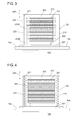
- FIG 4 is a cross-sectional view explaining a reactor including fin-like heat-transfer portions, as a heat-transfer portion according to another example.
- a heat-transfer portion 401 is provided at each of the side walls 209 and 210 of the case 103 like the example shown in Fig. 3 .
- the heat-transfer portion 401 includes a plurality of fin-like protrusions. For example, a plurality of plate pieces each having a triangular cross section and are arranged in the axial direction 205 of the coil 201. Each piece is arranged on the side wall 209 or 210 in parallel to the bottom surface 301 of the case 103.
- the heat-transfer portion 401 may be alternatively formed in other manner, for example, by arranging a plurality of needle-like protrusions on the side wall 209 and 210.
- the heat-transfer portions 401 is not in contact with the coil 201 or the inner core portion 202; however, may be in contact with the coil 201 and the inner core portion 202. If the heat-transfer portions 401 is not in contact with the coil 201 or the inner core portion 202, the outer core portion 203 is formed at that portion to ensure the magnetic circuit.
- the heat-transfer portions 401 Even if the heat-transfer portions 401 is not in contact with the coil 201 or the inner core portion 202, the inner wall surfaces of the side walls 209 and 210 are close to the coil 201 and the inner core portion 202 because of the presence of the heat-transfer portions 401 with reference to the base surfaces. Accordingly, the heat is likely dissipated from the coil 201 and the inner core portion 202 to the case 103. Also, since the heat-transfer portions 401 are provided, the surface area of the inner wall surfaces of the side walls 209 and 210 becomes large, and hence the heat is likely dissipated also in this point of view.
- Figures 5A and 5B are illustrations explaining a reactor including rectangular-plate-like heat-transfer portions at four inner corners of the case, as a heat-transfer portion according to still another example.
- Figure 5A is a side view when the reactor is cut along the side wall 212 at a position directly inside the side wall 212.
- Figure 5B is a plan view when the reactor is cut along the end-surface direction of the coil.
- Heat-transfer portions 501 are provided at positions corresponding to the four inner corners of the box-like case 103. If the case has a box-like shape and the coil 201 has a cylindrical shape, the distance between the coil 201 and the side walls 209 to 212 of the case 103 becomes large particularly at the four corners. By providing the heat-transfer portions 501, such portions of the coil 201 and the inner core portion 202 become close to the inner wall surface, and hence the heat can be likely radiated from the portions.
- Each heat-transfer portion 501 has a rectangular-plate-like shape in which a corner portion that is in contact with the inner core portion 202 is cut, and the rectangular plate is placed on the bottom surface 301 of the case 103.
- the heat-transfer portion 501 may have the shape of a rectangular plate or other shape.
- the upper surface of the heat-transfer portion 501 is also in contact with part of the lower end surface of the coil 201 in this example, and hence can make a contribution to dissipating the heat of the coil 201. However, the upper surface of the heat-transfer portion 501 may be separated from the lower end surface of the coil 201.
- the heat-transfer portion 501 is close to the lower end surface of the coil 201, and hence the heat from the coil 201 can be likely dissipated. Further, since the heat-transfer portion 501 is continued to the bottom surface 301 of the case 103, the heat is easily transferred from the coil 201 and the inner core portion 202 to the bottom surface 301.
- a heat-transfer portion like the heat-transfer portion 501 may be provided at the upper surface side of the reactor 1 instead of the heat-transfer portion 501 or in addition to the heat-transfer portion 501. Further, columnar heat-transfer portions each having a cross-sectional shape similar to that of the heat-transfer portion 501 and extending in the axial direction 205 of the coil 201 may be provided. In this case, the heat-radiation performance of a portion that is far from the side walls of the case 103 can be efficiently increased. The area between these heat-transfer portions is filled with the mixture of the magnetic material and the resin forming the outer core portion 203, and hence the magnetic circuit is ensured in the outer core portion 203.
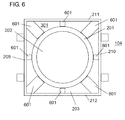
- FIG. 6 is an illustration explaining a reactor including heat-transfer portions in which a plurality of radially arranged plate-like portions are arrayed, as a heat-transfer portion according to yet another example.
- Heat-transfer portions 601 are formed by radially arranging a plurality of plate-like portions standing on the bottom surface 301 of the case 103 along the axial direction of the coil 201, around the inner core portion 202.
- the plate-like portion provided at each of the four inner corners has a larger thickness than that of the plate-like portion provided at the center of each of the side walls.
- the plate-like portions may have the same thickness, and the number of plate-like portions is not limited to this example.
- each heat-transfer portion 601 is in contact with the coil 201. Accordingly, the heat of the outer peripheral surface of the coil 201 can be easily dissipated to the side walls 209 to 212 of the case 103 and then to the bottom surface 301.
- the heat-transfer portion 601 does not have to be in contact with the coil 201. Further, the radially arranged heat-transfer portions 601 may be close to or may be in contact with the coil 201 and the inner core portion 202.
- the outer core portion 203 is formed between the plate-shape portions and the magnetic circuit can be ensured widely at that portion.
- FIGS 7A and 7B are illustrations explaining a reactor including spiral heat-transfer portions, as a heat-transfer portion according to a further example.
- Heat-transfer portions 701 are provided at the side walls 211 and 212 of the case 103.
- the two heat-transfer portions 701 are formed around the coil 201 in spiral forms.
- the heat-transfer portions 701 are in contact with the coil 201 (and the inner core portion 202) or are close to the coil 201 (and the inner core portion 202), thereby easily dissipating the heat.
- a gap is provided between line portions (for example, 701A and 701B) that form spirals.
- the outer core portion 203 is formed also in the gap, and hence the magnetic circuit can be formed even in that portion.
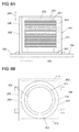
- FIGS 8A and 8B are illustrations explaining the configuration of a reactor including a case having an inner wall surface that is formed to correspond to the external shapes of the coil and the inner core portion, as a heat-radiation structure of a case according to another example.
- the heat-radiation structure according to this example is formed of an inner wall surface 801 that is formed in a columnar shape to correspond to the external shapes of the coil 201 and the inner core portion 202. Since the external shape of the case 103 is a rectangular-parallelepiped, the outer wall surface 208 is non-similar to the inner wall surface 801.
- An imaginary line 802 imaginarily indicates an inner wall surface if the inner wall surface is formed in a shape of a rectangular-parallelepiped that is similar to the outer wall surface 208.
- the columnar inner wall surface 801 is formed to correspond to the external shapes of the coil 201 and the inner core portion 202, the side wall of the case 103 is close to the coil 201 and the inner core portion 202.
- the outer core portion 203 is formed in a cylindrical shape to fill the gap in accordance with the shape of the inner wall surface 801.
- the thickness of the outer core portion 203 is uniformly decreased entirely in the circumferential direction of the cylindrical coil 201. Accordingly, the heat can be easily uniformly dissipated from the coil 201 and the inner core portion 202 to the bottom surface 301 of the case 103.
- the outer core portion 203 is formed in a cylindrical shape, variation in magnetic-circuit length can be reduced entirely in the circumferential direction of the coil 201. As the result, a designed magnetic characteristic can be more easily obtained. Further, an excessive core member of the outer core portion 203 can be reduced. It is to be noted that the example in which the coil 201 is cylindrical has been described; however, the shape of the coil 201 may be other shape.
- FIGS 9A and 9B are illustrations explaining a configuration of a reactor in which a coil is arranged in substantially parallel to the bottom surface of the case, as a heat-radiation structure of a case according to still another example, is described below.
- the heat-radiation structure according to this example includes the coil 201, the inner core portion 202, and a heat-transfer portion 701. If the heat-transfer portion 701 is formed in this way, the outer core portion 203 is formed to fill a gap in accordance with the shape.
- the bottom surface of the case 103 is further close to the coil 201 and the inner core portion 202, and hence the heat can be easily dissipated from the coil 201 and the inner core portion 202 to the bottom surface 301 of the case 103 through the heat-transfer portion 701.
- the end surface shape of the coil 201 may be other shape, such as a rectangle, an ellipsoid, or a race-track-like shape.
- FIGS 10A and 10B are illustrations explaining the configuration of a reactor including a case having an inner wall surface that is formed to correspond to the external shapes of a plurality of coil elements, as a heat-radiation structure of a case according to yet another example.
- a coil includes two coil elements 201A and 201B.
- Inner core portions 202A and 202B are respectively prepared for the coil elements 201A and 201B.
- the coil elements 201A and 201B each have an end surface of a rectangular shape (track-like shape) the corners of which are rounded.
- An inner wall surface 901 of the case 103 is formed to have a track-like cross-sectional shape to correspond to an envelope that connects the external shapes of the two coil elements 201A and 201B.
- the outer peripheral surface of the coil element 201A or 201B is parallel to the inner wall surface 901 even at the rounded corner portion of the track-like shape. Since the external shape of the case 103 is a rectangular-parallelepiped, the outer wall surface 208 is non-similar to the inner wall surface 901.
- the ratio of the long side to the short side of the rectangle serving as a base of the track-like shape is different from that of the rectangle of the cross section of the case 103, and hence the outer wall surface 208 is non-similar to the inner wall surface 901 also in this point of view.
- An imaginary line 902 imaginarily indicates an inner wall surface if the inner wall surface is formed in a shape of a rectangular-parallelepiped that is similar to the outer wall surface 208.
- the inner wall surface 901 having the track-like cross section is formed to correspond to the external shapes of the coil elements 201A and 201B, the side walls of the case 103 are close to the coil elements 201A and 201B. Accordingly, the heat can be easily dissipated from both the coil elements 201A and 201B to the bottom surface 301 of the case 103.
- the inner wall surface 901 can be formed to correspond to the envelope that connects the external shapes of the coil elements.
- an inner wall surface may be formed to correspond to each of the external shapes of the coil elements.
- an inner wall surface 903 shown in Fig. 10B is added, an inner wall surface is formed to correspond to the external shape of the coil element 201A or 201B.
- a section in which the coil elements 201A and 201B are parallel to the inner wall surface is provided in a portion between the coil elements 201A and 201B. Accordingly, the heat can be further effectively dissipated from the coil elements 201A and 201B.
- Figure 11 is an illustration explaining the configuration of a reactor including a case having an outer wall with a heat-radiation structure and a lid.
- Heat-transfer portions 1001 are provided at positions corresponding to four inner corners at the bottom surface 301 side of the case 103 like the example shown in Figs. 5A and 5B .
- the heat-transfer portions 1001 are an example for explaining the configuration of Fig. 11 , and the configuration is not limited to the heat-transfer portions 1001.
- the outer wall surface 208 at the side walls of the case 103 also has heat-radiation structures 1002.
- the heat-radiation structures 1002 each have a structure in which a plurality of plate-like pieces arranged in parallel to the bottom surface of the case 103 are arrayed on the outer wall surface 208 of the side walls of the case 103 in the axial direction of the coil 201.
- the heat-radiation structure of the outer wall surface 208 is not limited to this example.
- the heat-radiation structure may be formed of a plurality of needle-like protrusions arranged entirely on the outer wall surface of the side walls.
- the heat-radiation structures 1002 at the outer wall surface 208 of the case 103 as described above, the heat transferred from the coil 201 and the inner core portion 202 to the side walls of the case 103 can be further effectively dissipated. Accordingly, the heat-radiation performance of the entire reactor can be increased.
- the case 103 has a lid 1003 that closes an upper portion of the case 103.
- the upper surface of the case 103 is open and part of the outer core portion 203 is exposed.
- the upper side of the case 103 is closed with the lid 1003 that is, for example, made of aluminum.
- the upper surface of the reactor is in surface-contact with the lid 1003. Accordingly, the heat of the upper surface of the reactor is also dissipated through a path extending to the bottom surface 301 through the lid 1003 and the side walls of the case 103.
- the material of the lid 1003 may use a metal material such as aluminum or an aluminum alloy, or a ceramic such as silicon nitride, alumina, aluminum nitride, boron nitride, or silicon carbide. Also, if the lid 1003 and the case 103 are made of a conductive material like a metal material, the lid 1003 and the case 103 also function as shields for electromagnetic interference.
- heat-transfer portions 1004 are provided at positions corresponding to four corners at the upper surface side of the case 103.
- the heat-transfer portions 1004 are in contact with a side surface of an upper portion of the inner core portion 202 protruding from the coil 201, and are in contact with part of an upper end surface of the coil 201. Further, the heat-transfer portions 1004 are also in contact with the lid 1003 when the lid 1003 is closed. Accordingly, the heat can be further effectively dissipated from the coil 201 and the inner core portion 202 through the heat-transfer portions 1004 and the lid 1003.
- the heat-transfer portions 1004 may not be provided at the case 103 and may be provided at the lid 1003.
- the outer core portion 203 is molded in a shape that does not interfere with the heat-transfer portions of the lid 1003. Accordingly, the heat can be further effectively transferred from the coil 201 and the inner core portion 202 to the lid 1003.
- the application of the reactor of the present invention is not limited to the vehicle-mounted converter, and the reactor can be applied to a power converter with a relatively high output, such as a converter for an air conditioner.
- the reactor housed in the case may be manufactured also by preparing an assembled part of a coil and a core, housing the assembled part, and filling a separately prepared potting resin.
- the potting resin may use, for example, a mixture containing epoxy resin, urethane resin, PPS resin, polybutylene terephthalate (PBT) resin, or acrylonitrile butadiene styrene (ABS) resin; and also a filler made of at least one type of ceramics including silicon nitride, alumina, aluminum nitride, boron nitride, and silicon carbide. By containing the filler, the heat-radiation performance of the reactor is increased.
- the present invention can be applied not only to the reactor housed in the case such that the axial direction of the coil is parallel to the normal direction of the bottom surface of the case, but also to, for example, a reactor housed in a case such that the axial direction of a coil is parallel to the bottom surface of the case.
- the present invention has been described as the reactor the inner core portion of which is formed of the powder compact.
- the inner core portion may use a configuration formed of a stack in which electromagnetic steel sheets, which are typically silicon steel sheets, are stacked. The electromagnetic steel sheets more likely provide a magnetic core with a high saturation magnetic flux density than the powder compact does.
- the inner core portion has the higher saturation magnetic flux density than that of the outer core portion, and the outer core portion has the lower permeability than that of the inner core portion.
- the reactor to which the present invention is applied is not limited thereto.
- the outer core portion may be formed of a mixture of a magnetic material and a resin.
- the reactor according to the present invention can be used for a component of a power converter, for example, a converter mounted on a vehicle, such as a hybrid electric vehicle, a plug-in hybrid electric vehicle, an electric vehicle, or a fuel cell vehicle, or a converter mounted on an air conditioner.
- a converter mounted on a vehicle such as a hybrid electric vehicle, a plug-in hybrid electric vehicle, an electric vehicle, or a fuel cell vehicle, or a converter mounted on an air conditioner.
Landscapes
- Engineering & Computer Science (AREA)
- Power Engineering (AREA)
- Transportation (AREA)
- Mechanical Engineering (AREA)
- Dc-Dc Converters (AREA)
- Coils Of Transformers For General Uses (AREA)
Abstract
Description
- The present invention relates to a reactor used for a component of a power converter such as a vehicle-mounted direct current-direct current (DC-DC) converter.
- A hybrid electric vehicle, a plug-in hybrid electric vehicle, an electric vehicle, and the like, each need a converter that performs a step-up operation and a step-down operation when a travel motor is driven or a battery is charged. Even for a fuel cell vehicle, the output of a fuel cell is stepped up. One of parts of the converter is a reactor. For example, a reactor has a form in which a pair of coils each having an O-shaped magnetic core and a wire wound on the outer periphery of the magnetic core are arranged in parallel.
- PTL 1 discloses a reactor including a magnetic coil having an E-shaped cross section, the magnetic coil which is so-called a pot core. The magnetic core includes a columnar inner core portion inserted into a single coil, a cylindrical outer core portion arranged to cover the outer periphery of the coil, and a pair of disk-like coupling core portions arranged at both end surfaces of the coil. The coupling core portions couple the concentrically arranged inner and outer core portions with each other and hence the pot core forms a closed magnetic circuit.
- PTL 1: Japanese Unexamined Patent Application Publication No.
2009-033051 - In the reactor of PTL 1, the inner core portion and the coil are covered with the outer core portion and the coupling core portions. Such a structure hardly dissipates heat that is generated in the reactor due to a copper loss or an iron loss. Particularly in the vehicle-mounted converter, current with several hundreds of amperes may flow through the reactor. The amount of heat generated by the coil may increase, and hence the internal temperature of the reactor may rise to high temperatures of 100°C or higher.
- To address such a problem, the present invention provides a reactor that can effectively dissipate heat generated in a reactor even if the outside of a coil is covered with a core member.
- A reactor provided by the present invention includes a coil; a core having an inner core portion arranged inside the coil and an outer core portion covering the outside of the coil; and a case housing the coil and the core. The case has a heat-radiation structure at an inner wall surface, the heat-radiation structure being provided for at least one of the coil and the inner core portion. The outer core portion has a shape corresponding to the heat-radiation structure.
With this reactor, the heat-radiation structure for the at least one of the coil and the inner core portion is provided at the inner wall surface of the case. Accordingly, even if the outside of the coil is covered with a core member, the heat-radiation structure in the case can increase heat-radiation performance of the at least one of the coil and the inner core portion. - In this reactor, the heat-radiation structure may have a heat-transfer portion provided such that part of the inner wall surface of the case protrudes. Since the part of the inner wall surface of the case protrudes, the at least one of the coil and the inner core portion can be further close to the inner wall surface. Accordingly, the heat-radiation performance of the at least one of the coil and the inner core portion can be increased.
- The heat-radiation structure may be non-similar to an outer wall surface of the case, and may be formed of the inner wall surface that is formed to correspond to an external shape of the at least one of the coil and the inner core portion. Since the inner wall surface is formed to correspond to the external shape of the at least one of the coil and the inner core portion, the distance between the at least one of the coil and the inner core portion and the inner wall surface can be decreased equivalently at respective portions. Hence the heat-radiation performance of the at least one of the coil and the inner core portion can be increased.
- According to an aspect of the reactor, at least the outer core portion of the core is formed of a mixture of a magnetic material and a resin. Accordingly, even if the heat-radiation structure has a complicated shape, the outer core portion can be easily formed.
- Also, according to an aspect of the reactor, the coil is arranged such that an axial direction of the coil is in substantially parallel to a bottom surface of the case. Accordingly, the heat can be dissipated to the bottom surface of the case, the bottom surface which is being cooled.
- With the present invention, even if the outside of the coil is covered with the core member as described above, the heat-radiation performance of the at least one of the coil and the inner core portion can be increased.
- The above-described object and other objects, features, and advantages are described according to the following embodiment provided below with reference to the accompanying figures. In the figures, the same reference sign represents the same part even in different figures.
- [
Fig. 1] Figure 1 is an illustration showing an installation state of a reactor according to an embodiment of the present invention. - [
Fig. 2] Figure 2 is a perspective view showing the brief configuration of the reactor according to the embodiment of the present invention. - [
Fig. 3] Figure 3 is a cross-sectional view of the reactor for explaining the configuration of a heat-transfer portion. - [
Fig. 4] Figure 4 is a cross-sectional view explaining a reactor including fin-like heat-transfer portions, as a heat-transfer portion according to another example. - [
Fig. 5A] Figure 5A is an illustration explaining a reactor including rectangular-plate-like heat-transfer portions at four inner corners of a case, as a heat-transfer portion according to still another example. More particularly,Fig. 5A is a side view when the reactor is cut along aside wall 212 at a position directly inside theside wall 212. - [
Fig. 5B] Figure 5B is an illustration explaining the reactor including the rectangular-plate-like heat-transfer portions at the four inner corners of the case, as the heat-transfer portion according to still another example. More particularly,Fig. 5B is a plan view when the reactor is cut along an end-surface direction of the coil. - [
Fig. 6] Figure 6 is an illustration explaining a reactor including heat-transfer portions in which a plurality of radially arranged plate-like portions are arrayed, as a heat-transfer portion according to yet another example. - [
Fig. 7A] Figure 7A is an illustration explaining a reactor including spiral heat-transfer portions as a heat-transfer portion according to a further example. More particularly,Fig. 7A is a side view when the reactor is cut along theside wall 212 at a position directly inside theside wall 212. - [
Fig. 7B] Figure 7B is an illustration explaining the reactor including the spiral heat-transfer portions as the heat-transfer portion according to the further example. More particularly,Fig. 7B is a plan view when the reactor is cut along the end-surface direction of the coil. - [
Fig. 8A] Figure 8A is an illustration explaining the configuration of a reactor having a case with an inner wall surface formed to correspond to the external shapes of a coil and an inner core portion, as a heat-radiation structure of a case according to another example. More particularly,Fig. 8A is a side view when the reactor is cut along theside wall 212 at a position directly inside theside wall 212. - [
Fig. 8B] Figure 8B is an illustration explaining the configuration of the reactor having the case with the inner wall surface formed to correspond to the external shapes of the coil and the inner core portion, as the heat-radiation structure of the case according to another example. More particularly,Fig. 8B is a plan view when the reactor is cut along the end-surface direction of the coil. - [
Fig. 9A] Figure 9A is an illustration explaining the configuration of a reactor including a coil and an inner core portion arranged in substantially parallel to a bottom surface of a case, and a case having heat-transfer portions formed to correspond to the external shapes, as the heat-radiation structure of a case according to still another example. More particularly,Fig. 9A is a plan view when the reactor is cut along the end-surface direction of the coil. - [
Fig. 9B] Figure 9B is an illustration explaining the configuration of the reactor including the case having the heat-transfer portions formed to correspond to the external shapes of the coil and the inner core portion arranged in substantially parallel to the bottom surface of the case, as the heat-radiation structure of the case according to still another example. More particularly,Fig. 9B is a plan view when viewed from above. - [
Fig. 10A] Figure 10A is an illustration explaining the configuration of a reactor having a case with an inner wall surface formed to correspond to the external shapes of a plurality of coil elements, as a heat-radiation structure of a case according to yet another example. More particularly,Fig. 10A is a side view when the reactor is cut along theside wall 212 at a position directly inside theside wall 212. - [
Fig. 10B] Figure 10B is an illustration explaining the configuration of the reactor having the case with the inner wall surface formed to correspond to the external shapes of the plurality of coil elements, as the heat-radiation structure of the case according to yet another example. More particularly,Fig. 10B is a plan view when the reactor is cut along the end-surface direction of the coil. - [
Fig. 11] Figure 11 is an illustration explaining the configuration of a reactor including a case having an outer wall with a heat-radiation structure and a lid. Description of Embodiments - The present invention is described in more detail below.
Figure 1 is an illustration showing an installation state of a reactor according to an embodiment of the present invention. Areactor 101 according to the embodiment can be used for a part of a vehicle-mounted DC-DC converter. Thereactor 101 is housed in aconverter case 102 made of aluminum together with other parts. In this embodiment, thereactor 101 includes acase 103 made of aluminum and having, for example, a box-lid-like shape. Thereactor 101 is arranged in theconverter case 102 such that thecase 103 is fixed to aninner bottom surface 104 of theconverter case 102 by a bolt. A bottom surface of thecase 103 is in surface-contact with theinner bottom surface 104 of theconverter case 102. - In the vehicle-mounted converter, current with several hundreds of amperes may be applied to the
reactor 101, resulting in that thereactor 101 generates heat at high temperatures. In order to cool thereactor 101 and other parts, coolingwater 105 is introduced to an outer bottom surface of theconverter case 102. The heat generated by thereactor 101 is transferred to theconverter case 102 through the bottom surface of thecase 103 and is dissipated by the coolingwater 105. -
Figure 2 is a perspective view showing the brief configuration of the reactor according to the embodiment. Thereactor 101 includes acoil 201 and acore 204. Thecore 204 includes aninner core portion 202 arranged inside thecoil 201, and anouter core portion 203 covering the outside of thecoil 201. Thecase 103 included in thereactor 101 houses thecoil 201 and thecore 204. - In this
reactor 101, thecoil 201 is formed by winding a singlecontinuous wire 201w in a spiral form, and has anaxial direction 205 arranged in parallel to the normal direction of the bottom surface of thecase 103. Both ends of thewire 201w are connected with a semiconductor element and a battery of the converter. Thewire 201w preferably uses a coated wire having an insulating coating made of an insulating material on the outer periphery of a conductor made of a conducting material such as copper or aluminum. The conductor is formed of a rectangular wire made of copper. Thewire 201w uses a coated rectangular wire with an insulating coating of enamel. The cross section of the conductor of thewire 201w may not be the rectangular cross section, and may be any of various cross sections, such as a circular cross section, and a polygonal cross section. - The reactor having the above-described configuration can be preferably used for a particular purpose of use under electricity-application conditions in which a maximum current (direct current) is in a range from about 100 to 1000 A, an average voltage is in a range from about 100 to 1000 V, and a usable frequency is in a range from about 5 to 100 kHz, or typically, the reactor can be preferably used as a component of a vehicle-mounted power converter in a vehicle such as an electric vehicle, a hybrid electric vehicle, etc. With the particular purpose of use, it is expected that a preferably used configuration satisfies conditions in which an inductance when applied direct current is 0 A is in a range from 10 µH to 2 mH and an inductance when applied current is a maximum application current is 10% or more of the inductance when applied current is 0 A. When the reactor is a vehicle-mounted part, the reactor containing the case preferably has a capacity in a range from about 0.2 litters (200 cm3) to about 0.8 litters (800 cm3).
- The
coil 201 forms a single coil element. Alternatively, a single wire may form a plurality of coil elements and these coil elements may be housed in a case. The plurality of coil elements do not have to be formed of a single wire, and may be formed of separate wires. The wires may form an integrated coil by bonding ends of the wires by welding or the like. For welding the separate wires, for example, tungsten inert gas (TIG) welding, laser welding, or resistance welding may be used. Alternatively, the ends of the wires may be bonded by contact bonding, cold pressure welding, or vibration welding. - Both ends of the
wire 201w forming thecoil 201 are led from turns by a certain amount to the outside of theouter core portion 203. The insulating coating is removed and the conductor portions are exposed. Terminal members made of a conductive material such as copper or aluminum are connected with the exposed conductor portions. Thecoil 201 is connected with a battery etc. through the terminal members. The connection between both ends of thewire 201w and the terminal members can use welding such as TIG welding or contact bonding etc. - The core 204 forms a closed magnetic circuit because the
inner core portion 202 and theouter core portion 203 are integrated. In this embodiment, theinner core portion 202 and theouter core portion 203 are formed of different forming materials, and hence have different magnetic properties. To be more specific, theinner core portion 202 has a higher saturation magnetic flux density than that of theouter core portion 203, and theouter core portion 203 has a lower permeability than that of theinner core portion 202. - The
inner core portion 202 has an external shape extending along the shape of the inner peripheral surface of the coil 201 (if a plurality of coil elements are formed, these coil elements). In this case, theinner core portion 202 has a columnar external shape. Alternatively, theinner core portion 202 may have an external shape like a rectangular-parallelepiped with an end-surface shape being a rectangular with rounded corners (a track-like shape), or other external shape. Theinner core portion 202 may be entirely formed of a powder compact, and may have a configuration in which a gap member, an air gap, or a bonding member is not interposed. Alternatively, theinner core portion 202 may be formed of a plurality of cores with a gap member, an air gap, or a bonding member interposed therebetween. - The powder compact is typically obtained by molding a soft magnetic powder having an insulating coating on the surface thereof, and burning the soft magnetic powder at a heat-resistant temperature or lower of the insulating coating. A mixed powder in which a binder is appropriately mixed to the soft magnetic powder may be used, or a powder having a coating made of silicone resin as an insulating coating may be used. The saturation magnetic flux density of the powder compact can be changed depending on the material of the soft magnetic powder, and by adjusting the mixing ratio of the soft magnetic powder and the binder, and the amounts of various coatings. For example, by using a soft magnetic powder with a high saturation magnetic flux density, or by decreasing the contained amount of the binder and increasing the ratio of the soft magnetic material, a powder compact with a high saturation magnetic flux density is obtained. The saturation magnetic flux density may be increased even by changing a molding pressure, more particularly, by increasing the molding pressure. The soft magnetic powder may be selected and the molding pressure may be adjusted to obtain a desirable saturation magnetic flux density.
- The soft magnetic powder may be an iron-family metal powder, such as iron (Fe), cobalt (Co), or nickel (Ni); a Fe base alloy powder, such as Fe-silicon (Si), Fe-Ni, Fe-aluminum (Al), Fe-Co, Fe-chromium (Cr), Fe-Si-Al; or alternatively, a rare earth metal powder or a ferrite powder. In particular, the Fe base metal powder likely provides a powder compact with a high saturation magnetic flux density. Such a powder can be produced by atomizing (with gas or water), mechanical pulverizing, or other method. If a powder formed of a nanocrystal material having a nanosized crystal, or more preferably, a powder formed of an anisotropic nanocrystal material is used, a powder compact which is highly anisotropic and has a low coercive force is obtained. The insulating coating formed on the soft magnetic powder uses, for example, a phosphate compound, a silicon compound, a zirconium compound, or a boron compound. The binder may use a thermoplastic resin, a non-thermoplastic resin, or a higher fatty acid. The binder is lost or changed to an insulator such as silica by burning. Since the powder compact has an insulator such as the insulating coating, the soft magnetic powder is insulated from other soft magnetic powder, and hence an eddy current loss can be reduced. Even if power with a high frequency is applied to the coil, the loss can be reduced.
- The
inner core portion 202 contains a configuration that is entirely arranged inside the coil (element), and also a configuration that partly protrudes from the coil (element). In an example shown inFig. 2 , theinner core portion 202 has a larger length in the axial direction of thecoil 201 than the length of thecoil 201. Both ends of theinner core portion 202 protrude from end surfaces of thecoil 201. The length of theinner core portion 202 may be equivalent to or slightly smaller than the length of thecoil 201. If the length of theinner core portion 202 is equivalent to or larger than the length of thecoil 201, the magnetic flux generated by thecoil 201 can sufficiently pass through theinner core portion 202. - In this embodiment, the
outer core portion 203 is formed to cover substantially entirely thecoil 201 and theinner core portion 202. In other words, theouter core portion 203 substantially covers the entire outer periphery of thecoil 201, both end surfaces of thecoil 201, and both end surfaces of theinner core portion 202. Theinner core portion 202 and theouter core portion 203 are bonded together by the resin forming theouter core portion 203 without an adhesive member interposed therebetween. By such bonding, thecore 204 can be entirely integrated without a gap. - The
outer core portion 203 has an external shape of a rectangular-parallelepiped corresponding to the inner wall surface of the case as a basic external shape. However, the shape of theouter core portion 203 is not particularly limited as long as a closed magnetic circuit can be formed. The outer side of thecoil 201 may not be partly covered with theouter core portion 203 and may be exposed. - The
outer core portion 203 can be entirely formed of a mixture (hardened compact) of a magnetic material and a resin. The hardened compact can be typically formed by injection molding or cast molding. The injection molding normally mixes a soft magnetic powder (or a mixed powder to which a non-magnetic powder is further added if required) and a binder resin having fluidity, molds the mixed fluid into a mold with a predetermined pressure, and then hardens the binder resin. The cast molding obtains the mixed fluid like the injection molding, and then injects the mixed fluid into a mold to mold and harden the mixed fluid without application of a pressure. In either of the molding methods, the binder resin can preferably use a thermosetting resin, such as epoxy resin, phenol resin, or silicone resin. If the binder resin uses the thermosetting resin, the compact is heated and hence the resin is thermally hardened. The binder resin may alternatively use a roomtemperature-setting resin or a low-temperature-setting resin. In this case, the resin is left at a temperature in a range from a room temperature to a relatively low temperature to harden the resin. The binder resin, which is a non-magnetic material, remains in the hardened compact by a large amount. Even if the hardened compact uses the same soft magnetic powder as that of the powder compact, the hardened compact has a lower saturation magnetic flux density and a lower permeability than those of the powder compact. - In the case in which the injection molding or cast molding is used, the permeability of the outer core portion can be adjusted by changing the contained amounts of the soft magnetic powder (or non-magnetic powder) and the binder resin if sintering is not performed, or by changing the contained amounts of the soft magnetic powder and the non-magnetic powder if sintering is performed. For example, if the contained amount of the soft magnetic powder decreases, the permeability tends to decrease. The permeability of the
outer core portion 203 is preferably adjusted so that thereactor 101 has a desirable inductance. - The soft magnetic powder for the
outer core portion 203 can use a powder equivalent to the soft magnetic powder for the above-describedinner core portion 202.
An insulator is preferably arranged at a position at which thecore 204 is in contact with thecoil 201 in order to further increase insulation between both the parts. For example, an insulating tape may be attached to the inner and outer peripheral surfaces of thecoil 201, or insulating paper or an insulating sheet may be arranged. A bobbin made of an insulating material may be arranged on the outer periphery of theinner core portion 202. The forming material of the bobbin can preferably use an insulating resin, such as polyphenylene sulfide (PPS) resin, liquid crystal polymer (LCP), or polytetrafluoroethylene (PTFE) resin. - With this
reactor 101, since the saturation magnetic flux density of theinner core portion 202 is higher than that of theouter core portion 203, if the total magnetic flux passing through theinner core portion 202 is equivalent to the total magnetic flux passing through an inner core of a magnetic core (a uniform core) having a shape similar to the shape of the core of thereactor 101 and entirely having a uniform saturation magnetic flux density, the cross-sectional area of the inner core portion 202 (a plane through which the magnetic flux passes) can be smaller than the cross-sectional area of the inner core of the uniform core. Since theinner core portion 202 is downsized, thecore 204 can be downsized, and as the result, thereactor 101 can be downsized. Also, with thereactor 101, since theinner core portion 202 has the high saturation magnetic flux density and theouter core portion 203 has the low permeability, thereactor 101 can have a desirable inductance. Further, with thereactor 101, in a case in which a gap containing an adhesive is not present entirely in thecore 204, a phenomenon in which a magnetic flux leaking at the gap affects thecoil 201 does not occur. Hence, theinner core portion 202 can be arranged closely to the inner peripheral surface of thecoil 201. Accordingly, the gap between the outer peripheral surface of theinner core portion 202 and the inner peripheral surface of thecoil 201 can be decreased. Also in this point of view, thereactor 101 can be downsized. - In addition, if the
reactor 101 does not use an adhesive, a bonding process for a gap member is not required when theinner core portion 202 is formed, resulting in good productivity. In particular, with thereactor 101, theinner core portion 202 and theouter core portion 203 are bonded together by the forming resin of theouter core portion 203 to form thecore 204 simultaneously when theouter core portion 203 is formed, and as the result, thereactor 101 can be manufactured. Accordingly, the manufacturing process is simplified, and also in this point of view, the productivity is increased. - Also, if the
reactor 101 has a structure without an adhesive, a phenomenon in which mismatching appears in inductance due to variation of the thickness of the adhesive hardly occurs. Further, with thereactor 101, since theinner core portion 202 is the powder compact, the saturation magnetic flux density can be easily adjusted, and even if theinner core portion 202 has a complicated three-dimensional shape, theinner core portion 202 can be easily formed. In addition, since theouter core portion 203 has a resin component, theouter core portion 203 can be protected from the external environment, such as dust and corrosion, and can be mechanically protected.
In particular, with thereactor 101, since thecoil 201 is entirely covered with theouter core portion 203, theouter core portion 203 can be easily formed and can sufficiently protect thecoil 201. As described above, thereactor 101 have various advantages. - Further, with the
reactor 101, although thecoil 201 is entirely covered with theouter core portion 203, the internal temperature can be maintained low. As described with reference toFig. 1 , the bottom surface of thereactor 101 is cooled, and hence the internal temperature at the bottom surface side is relatively likely decreased. In contrast, the upper surface side of thereactor 101 is the farthest from the bottom surface of thecase 103, and is not covered with the case unlike the bottom surface and the side surfaces of thereactor 101. The heat is mainly dissipated through a path extending from theinner core portion 202 to the bottom surface and a path extending to the bottom surface through theouter core portion 203 and the side walls of the case. The temperature is relatively likely increased. In particular, if theouter core portion 203 is molded of a mixture of a magnetic material and a resin, theouter core portion 203 has a lower thermal conductivity than that of theinner core portion 202. The tendency in which the temperature is relatively likely increased is promoted. - To reduce a rise in internal temperature, in the
reactor 101 according to this embodiment, thecase 103 includes a heat-transfer portion 206 at aninner wall surface 207, as a heat radiating structure for at least one of thecoil 201 and theinner core portion 202. The heat-transfer portion 206 is formed such that part of theinner wall surface 207 of thecase 103 protrudes, and forms part or entirety of theinner wall surface 207 that is non-similar to anouter wall surface 208. Since the heat-transfer portion 206 is provided, theouter core portion 203 is formed to correspond to the shape of the heat-transfer portion 206, and hence the at least one of thecoil 201 and theinner core portion 202 is close to theinner wall surface 207 as compared with a case in which theinner wall surface 207 is similar to theouter wall surface 208. Accordingly, the heat-radiation performance of the at least one of thecoil 201 and theinner core portion 202 can be increased. - The heat-
transfer portion 206 is provided at each ofside walls side walls 209 to 212 of thecase 103, and forms part of the inner wall surfaces of these side walls. The basic shape of theinner wall surface 207 is a rectangular-parallelepiped that is similar to theouter wall surface 208. However, since the heat-transfer portion 206 that protrudes from the base surface toward thecoil 201 and theinner core portion 202 is provided, theinner wall surface 207 is non-similar to theouter wall surface 208. With the protrusion, (the heat-transfer portion 206 of) theinner wall surface 207 is in contact with thecoil 201 and theinner core portion 202. - The heat-
transfer portion 206 is not limited to a configuration that is integrally molded with thecase 103 as part of thecase 103, and includes a configuration that is formed of a material which is the same as or different from the material of the body of thecase 103, that is formed separately from the body, and that is fixed to the body.
The material of the heat-transfer portion 206 may use a metal material such as aluminum or an aluminum alloy, or a ceramic such as silicon nitride, alumina, aluminum nitride, boron nitride, or silicon carbide. Since the heat-transfer portion 206 with a high thermal conductivity is in contact with (or is close to) thecoil 201 and the inner core portion 202 (substantially) not through theouter core portion 203, the heat in thereactor 101 is effectively dissipated. It is to be noted that if the heat-transfer portion 206 is also used as a rib, the material of the heat-transfer portion 206 has to be selected by also taking into account the mechanical strength. - When the
reactor 101 is manufactured, for example, thecoil 201 and theinner core portion 202 formed of the powder compact are prepared, and theinner core portion 202 is inserted into thecoil 201. At this time, an insulator may be appropriately arranged between thecoil 201 and theinner core portion 202. This assembled part of thecoil 201 and theinner core portion 202 is housed in thecase 103 provided with the heat-transfer portion 206.
In this state, the mixed fluid of the magnetic material and the binder resin forming theouter core portion 203 is properly applied into thecase 103. In this way, since theouter core portion 203 is formed by filling the mixture of the magnetic material and the resin, even if theinner wall surface 207 of thecase 103 has a complicated shape for the heat-radiation structure, theouter core portion 203 can be formed to correspond to the heat-radiation structure, and thus thereactor 101 can be relatively easily manufactured. - The heat-
transfer portion 206 is not provided at theside wall case 103 in this example. Owing to this, in the vicinity of theside walls outer core portion 203 is continuously formed in the axial direction of thecoil 201 so as to connect one end and the other end of theinner core portion 202. In this portion, a ringshaped (closed) magnetic circuit extending along theinner core portion 202 and theouter core portion 203, from the inside, to the outside, and then to the inside of thecoil 201, is widely ensured. As the result, a desirable magnetic characteristic can be provided although the heat-transfer portion 206 is provided at theinner wall surface 207 of thecase 103. The inner wall provided with the heat-transfer portion 206 is not limited to this example, and the inner wall can be properly determined as long as the magnetic circuit can be ensured. - The heat-
transfer portion 206 includes aprotrusion 206A protruding from theinner wall surface 207 of thecase 103 so as to be in contact with the outer peripheral surface of thecoil 201, and aprotrusion 206B protruding from theinner wall surface 207 of thecase 103 so as to be in contact with theinner core portion 202 protruding from the end surface of thecoil 201. Theprotrusion 206A has a concave surface corresponding to the outer peripheral surface of thecoil 201 as a contact surface, and theprotrusion 206B has a concave surface corresponding to the outer peripheral surface of theinner core portion 202 as a contact surface. With these concave surfaces, the contact (or close) area is larger than that in a case in which these surfaces are flat. The heat can be likely dissipated from thecoil 201 and theinner core portion 202 by that amount. -
Figure 3 is a cross-sectional view of the reactor for explaining the configuration of the heat-transfer portion. In the heat-transfer portion 206, theprotrusion 206A is continued to theprotrusion 206B in theaxial direction 205 of thecoil 201. Further, theprotrusion 206B is provided at each of theside walls case 103 and is continued to abottom surface 301 of thecase 103. The heat from thecoil 201 is transferred to thebottom surface 301 of thecase 103 through theprotrusions coil 201 as compared with a case in which only theprotrusion 206A is provided. Also, since theprotrusion 206B is continued to thebottom surface 301 of thecase 103, the heat from theinner core portion 202 can be also likely transferred to thebottom surface 301. In addition, an upper end surface of theprotrusion 206B is in contact with part of a lower end surface of thecoil 201. Hence, theprotrusion 206B can make a contribution to cooling thecoil 201. - Further, in the
reactor 101, alower end portion 302 of theinner core portion 202 is in surface-contact with thebottom surface 301 of thecase 103. Theinner core portion 202 has a higher thermal conductivity than that of theouter core portion 203. Since the lower end surface of theinner core portion 203 is in contact with thebottom surface 301, the heat can be dissipated to thecase 103 even through theinner core portion 203. The heat-radiation performance of theentire reactor 101 can be further increased. - In this case, the heat-
transfer portion 206 includes theprotrusions transfer portion 206 may include only one of theprotrusions protrusion 206B may be provide at an upper end side of thecoil 201. The upper surface side of thereactor 101 is not covered with thecase 103. In particular, a center portion is far from theside walls 209 to 212 of thecase 103, and hence the temperature of the center portion likely rises. If the heat-transfer portion is provided at the upper end side of thecoil 201, the heat at the upper surface side of thereactor 101 can be effectively dissipated. Also, theprotrusions coil 201 and theinner core portion 202 by way of employing the concave surfaces; however, theprotrusions coil 201 and theinner core portion 202 by way of employing flat surfaces or convex surfaces. Since thecoil 201 has the cylindrical shape, theinner core portion 202 has the columnar shape, and the inner wall surface of thecase 103 has the shape of a rectangular-parallelepiped, if a flat surface or a convex surface is employed, part of the heat-transfer portion becomes close to thecoil 201 or theinner core portion 202 as compared with the other part. However, the close part protrudes from the base surface of the inner wall, and hence the heat can be likely dissipated from thecoil 201 or theinner core portion 202 by that amount. -
Figure 4 is a cross-sectional view explaining a reactor including fin-like heat-transfer portions, as a heat-transfer portion according to another example. A heat-transfer portion 401 is provided at each of theside walls case 103 like the example shown inFig. 3 . The heat-transfer portion 401 includes a plurality of fin-like protrusions. For example, a plurality of plate pieces each having a triangular cross section and are arranged in theaxial direction 205 of thecoil 201. Each piece is arranged on theside wall bottom surface 301 of thecase 103. The heat-transfer portion 401 may be alternatively formed in other manner, for example, by arranging a plurality of needle-like protrusions on theside wall transfer portions 401 is not in contact with thecoil 201 or theinner core portion 202; however, may be in contact with thecoil 201 and theinner core portion 202. If the heat-transfer portions 401 is not in contact with thecoil 201 or theinner core portion 202, theouter core portion 203 is formed at that portion to ensure the magnetic circuit. - Even if the heat-
transfer portions 401 is not in contact with thecoil 201 or theinner core portion 202, the inner wall surfaces of theside walls coil 201 and theinner core portion 202 because of the presence of the heat-transfer portions 401 with reference to the base surfaces. Accordingly, the heat is likely dissipated from thecoil 201 and theinner core portion 202 to thecase 103. Also, since the heat-transfer portions 401 are provided, the surface area of the inner wall surfaces of theside walls -
Figures 5A and 5B are illustrations explaining a reactor including rectangular-plate-like heat-transfer portions at four inner corners of the case, as a heat-transfer portion according to still another example.Figure 5A is a side view when the reactor is cut along theside wall 212 at a position directly inside theside wall 212.Figure 5B is a plan view when the reactor is cut along the end-surface direction of the coil. Heat-transfer portions 501 are provided at positions corresponding to the four inner corners of the box-like case 103. If the case has a box-like shape and thecoil 201 has a cylindrical shape, the distance between thecoil 201 and theside walls 209 to 212 of thecase 103 becomes large particularly at the four corners. By providing the heat-transfer portions 501, such portions of thecoil 201 and theinner core portion 202 become close to the inner wall surface, and hence the heat can be likely radiated from the portions. - Each heat-
transfer portion 501 has a rectangular-plate-like shape in which a corner portion that is in contact with theinner core portion 202 is cut, and the rectangular plate is placed on thebottom surface 301 of thecase 103. The heat-transfer portion 501 may have the shape of a rectangular plate or other shape. The upper surface of the heat-transfer portion 501 is also in contact with part of the lower end surface of thecoil 201 in this example, and hence can make a contribution to dissipating the heat of thecoil 201. However, the upper surface of the heat-transfer portion 501 may be separated from the lower end surface of thecoil 201. Even in this case, the heat-transfer portion 501 is close to the lower end surface of thecoil 201, and hence the heat from thecoil 201 can be likely dissipated. Further, since the heat-transfer portion 501 is continued to thebottom surface 301 of thecase 103, the heat is easily transferred from thecoil 201 and theinner core portion 202 to thebottom surface 301. - A heat-transfer portion like the heat-
transfer portion 501 may be provided at the upper surface side of the reactor 1 instead of the heat-transfer portion 501 or in addition to the heat-transfer portion 501. Further, columnar heat-transfer portions each having a cross-sectional shape similar to that of the heat-transfer portion 501 and extending in theaxial direction 205 of thecoil 201 may be provided. In this case, the heat-radiation performance of a portion that is far from the side walls of thecase 103 can be efficiently increased. The area between these heat-transfer portions is filled with the mixture of the magnetic material and the resin forming theouter core portion 203, and hence the magnetic circuit is ensured in theouter core portion 203. -
Figure 6 is an illustration explaining a reactor including heat-transfer portions in which a plurality of radially arranged plate-like portions are arrayed, as a heat-transfer portion according to yet another example. Heat-transfer portions 601 are formed by radially arranging a plurality of plate-like portions standing on thebottom surface 301 of thecase 103 along the axial direction of thecoil 201, around theinner core portion 202. In this example, the plate-like portion provided at each of the four inner corners has a larger thickness than that of the plate-like portion provided at the center of each of the side walls. The plate-like portions may have the same thickness, and the number of plate-like portions is not limited to this example. - A surface of each heat-
transfer portion 601 is in contact with thecoil 201. Accordingly, the heat of the outer peripheral surface of thecoil 201 can be easily dissipated to theside walls 209 to 212 of thecase 103 and then to thebottom surface 301. The heat-transfer portion 601 does not have to be in contact with thecoil 201. Further, the radially arranged heat-transfer portions 601 may be close to or may be in contact with thecoil 201 and theinner core portion 202. Theouter core portion 203 is formed between the plate-shape portions and the magnetic circuit can be ensured widely at that portion. -
Figures 7A and 7B are illustrations explaining a reactor including spiral heat-transfer portions, as a heat-transfer portion according to a further example. Heat-transfer portions 701 are provided at theside walls case 103. The two heat-transfer portions 701 are formed around thecoil 201 in spiral forms. The heat-transfer portions 701 are in contact with the coil 201 (and the inner core portion 202) or are close to the coil 201 (and the inner core portion 202), thereby easily dissipating the heat. A gap is provided between line portions (for example, 701A and 701B) that form spirals. Theouter core portion 203 is formed also in the gap, and hence the magnetic circuit can be formed even in that portion. By forming the heat-transfer portions 701 in spiral forms, the spiral forms allow the heat of thecoil 201 to be relatively uniformly radiated and make a contribution to forming the magnetic circuit. -
Figures 8A and 8B are illustrations explaining the configuration of a reactor including a case having an inner wall surface that is formed to correspond to the external shapes of the coil and the inner core portion, as a heat-radiation structure of a case according to another example. The heat-radiation structure according to this example is formed of aninner wall surface 801 that is formed in a columnar shape to correspond to the external shapes of thecoil 201 and theinner core portion 202. Since the external shape of thecase 103 is a rectangular-parallelepiped, theouter wall surface 208 is non-similar to theinner wall surface 801. Animaginary line 802 imaginarily indicates an inner wall surface if the inner wall surface is formed in a shape of a rectangular-parallelepiped that is similar to theouter wall surface 208. As it is found through comparison between theinner wall surface 801 and theimaginary line 802 in the figure, since the columnarinner wall surface 801 is formed to correspond to the external shapes of thecoil 201 and theinner core portion 202, the side wall of thecase 103 is close to thecoil 201 and theinner core portion 202. Also, since theinner wall surface 801 is formed in this way, theouter core portion 203 is formed in a cylindrical shape to fill the gap in accordance with the shape of theinner wall surface 801. The thickness of theouter core portion 203 is uniformly decreased entirely in the circumferential direction of thecylindrical coil 201. Accordingly, the heat can be easily uniformly dissipated from thecoil 201 and theinner core portion 202 to thebottom surface 301 of thecase 103. - Also, since the
outer core portion 203 is formed in a cylindrical shape, variation in magnetic-circuit length can be reduced entirely in the circumferential direction of thecoil 201. As the result, a designed magnetic characteristic can be more easily obtained. Further, an excessive core member of theouter core portion 203 can be reduced. It is to be noted that the example in which thecoil 201 is cylindrical has been described; however, the shape of thecoil 201 may be other shape. -
Figures 9A and 9B are illustrations explaining a configuration of a reactor in which a coil is arranged in substantially parallel to the bottom surface of the case, as a heat-radiation structure of a case according to still another example, is described below. The heat-radiation structure according to this example includes thecoil 201, theinner core portion 202, and a heat-transfer portion 701. If the heat-transfer portion 701 is formed in this way, theouter core portion 203 is formed to fill a gap in accordance with the shape. Also, since thecoil 201, theinner core portion 202, and the heat-transfer portion 701 are formed, the bottom surface of thecase 103 is further close to thecoil 201 and theinner core portion 202, and hence the heat can be easily dissipated from thecoil 201 and theinner core portion 202 to thebottom surface 301 of thecase 103 through the heat-transfer portion 701. - It is to be noted that the example in which the
coil 201 is cylindrical and has the circular end surface has been described; however, the end surface shape of thecoil 201 may be other shape, such as a rectangle, an ellipsoid, or a race-track-like shape. -
Figures 10A and 10B are illustrations explaining the configuration of a reactor including a case having an inner wall surface that is formed to correspond to the external shapes of a plurality of coil elements, as a heat-radiation structure of a case according to yet another example. In this example, a coil includes twocoil elements Inner core portions coil elements coil elements - An
inner wall surface 901 of thecase 103 is formed to have a track-like cross-sectional shape to correspond to an envelope that connects the external shapes of the twocoil elements coil element inner wall surface 901 even at the rounded corner portion of the track-like shape. Since the external shape of thecase 103 is a rectangular-parallelepiped, theouter wall surface 208 is non-similar to theinner wall surface 901. The ratio of the long side to the short side of the rectangle serving as a base of the track-like shape is different from that of the rectangle of the cross section of thecase 103, and hence theouter wall surface 208 is non-similar to theinner wall surface 901 also in this point of view. Animaginary line 902 imaginarily indicates an inner wall surface if the inner wall surface is formed in a shape of a rectangular-parallelepiped that is similar to theouter wall surface 208. Similarly to the example ofFigs. 8A and 8B , as it is found through comparison between theinner wall surface 901 and theimaginary line 902 in the figure, since theinner wall surface 901 having the track-like cross section is formed to correspond to the external shapes of thecoil elements case 103 are close to thecoil elements coil elements bottom surface 301 of thecase 103. If the plurality of coil elements are provided as described above, theinner wall surface 901 can be formed to correspond to the envelope that connects the external shapes of the coil elements. - Even if the plurality of coil elements are provided, an inner wall surface may be formed to correspond to each of the external shapes of the coil elements. For example, if an
inner wall surface 903 shown inFig. 10B is added, an inner wall surface is formed to correspond to the external shape of thecoil element coil elements coil elements coil elements -
Figure 11 is an illustration explaining the configuration of a reactor including a case having an outer wall with a heat-radiation structure and a lid. Heat-transfer portions 1001 are provided at positions corresponding to four inner corners at thebottom surface 301 side of thecase 103 like the example shown inFigs. 5A and 5B . The heat-transfer portions 1001 are an example for explaining the configuration ofFig. 11 , and the configuration is not limited to the heat-transfer portions 1001. - In the reactor of
Fig. 11 , theouter wall surface 208 at the side walls of thecase 103 also has heat-radiation structures 1002. The heat-radiation structures 1002 each have a structure in which a plurality of plate-like pieces arranged in parallel to the bottom surface of thecase 103 are arrayed on theouter wall surface 208 of the side walls of thecase 103 in the axial direction of thecoil 201. However, the heat-radiation structure of theouter wall surface 208 is not limited to this example. For example, the heat-radiation structure may be formed of a plurality of needle-like protrusions arranged entirely on the outer wall surface of the side walls. - By providing the heat-
radiation structures 1002 at theouter wall surface 208 of thecase 103 as described above, the heat transferred from thecoil 201 and theinner core portion 202 to the side walls of thecase 103 can be further effectively dissipated. Accordingly, the heat-radiation performance of the entire reactor can be increased. - Further, in this example, the
case 103 has alid 1003 that closes an upper portion of thecase 103. In the above-described examples, the upper surface of thecase 103 is open and part of theouter core portion 203 is exposed. In the example ofFig. 10 , the upper side of thecase 103 is closed with thelid 1003 that is, for example, made of aluminum. The upper surface of the reactor is in surface-contact with thelid 1003. Accordingly, the heat of the upper surface of the reactor is also dissipated through a path extending to thebottom surface 301 through thelid 1003 and the side walls of thecase 103. The material of thelid 1003 may use a metal material such as aluminum or an aluminum alloy, or a ceramic such as silicon nitride, alumina, aluminum nitride, boron nitride, or silicon carbide. Also, if thelid 1003 and thecase 103 are made of a conductive material like a metal material, thelid 1003 and thecase 103 also function as shields for electromagnetic interference. - Further, in this example, heat-
transfer portions 1004 are provided at positions corresponding to four corners at the upper surface side of thecase 103. The heat-transfer portions 1004 are in contact with a side surface of an upper portion of theinner core portion 202 protruding from thecoil 201, and are in contact with part of an upper end surface of thecoil 201. Further, the heat-transfer portions 1004 are also in contact with thelid 1003 when thelid 1003 is closed. Accordingly, the heat can be further effectively dissipated from thecoil 201 and theinner core portion 202 through the heat-transfer portions 1004 and thelid 1003. It is to be noted that the heat-transfer portions 1004 may not be provided at thecase 103 and may be provided at thelid 1003. In this case, theouter core portion 203 is molded in a shape that does not interfere with the heat-transfer portions of thelid 1003. Accordingly, the heat can be further effectively transferred from thecoil 201 and theinner core portion 202 to thelid 1003. - The above-described embodiment does not limit the technical scope of the present invention, and various modifications and applications can be made within the scope of the present invention. For example, the application of the reactor of the present invention is not limited to the vehicle-mounted converter, and the reactor can be applied to a power converter with a relatively high output, such as a converter for an air conditioner. Further, the reactor housed in the case may be manufactured also by preparing an assembled part of a coil and a core, housing the assembled part, and filling a separately prepared potting resin. The potting resin may use, for example, a mixture containing epoxy resin, urethane resin, PPS resin, polybutylene terephthalate (PBT) resin, or acrylonitrile butadiene styrene (ABS) resin; and also a filler made of at least one type of ceramics including silicon nitride, alumina, aluminum nitride, boron nitride, and silicon carbide. By containing the filler, the heat-radiation performance of the reactor is increased. Further, the present invention can be applied not only to the reactor housed in the case such that the axial direction of the coil is parallel to the normal direction of the bottom surface of the case, but also to, for example, a reactor housed in a case such that the axial direction of a coil is parallel to the bottom surface of the case.
- In the above-described embodiment, the present invention has been described as the reactor the inner core portion of which is formed of the powder compact. For another example, the inner core portion may use a configuration formed of a stack in which electromagnetic steel sheets, which are typically silicon steel sheets, are stacked. The electromagnetic steel sheets more likely provide a magnetic core with a high saturation magnetic flux density than the powder compact does. Further, in the above-described reactor, the inner core portion has the higher saturation magnetic flux density than that of the outer core portion, and the outer core portion has the lower permeability than that of the inner core portion. However, the reactor to which the present invention is applied is not limited thereto. For example, not only the outer core portion but also the inner core portion may be formed of a mixture of a magnetic material and a resin.
The embodiment and the examples disclosed herein are mere examples and do not intend to provide limitation. The scope of the present invention is not defined by the above description but is defined by the scope of the claims. It is intended that the scope of the present invention contains the meanings equivalent to the scope of the claims and all modifications within the scope of the claims. - The reactor according to the present invention can be used for a component of a power converter, for example, a converter mounted on a vehicle, such as a hybrid electric vehicle, a plug-in hybrid electric vehicle, an electric vehicle, or a fuel cell vehicle, or a converter mounted on an air conditioner.
-
- 101
- reactor
- 102
- converter case
- 103
- case of reactor
- 201
- coil
- 201A, 201B
- coil element
- 201w
- wire
- 202
- inner core portion
- 203
- outer core portion
- 204
- core
- 206, 401, 501, 601, 701, 1001, 1004
- heat-transfer portion
- 206A, 206B
- protrusion
- 207, 801, 901
- inner wall surface
- 208
- outer wall surface
- 209, 210, 211, 212
- side wall
- 301
- bottom surface of case
- 1002
- heat-radiation structure of outer wall
- 1003
- lid of case
Claims (5)
- A reactor comprising: a coil; a core having an inner core portion arranged inside the coil and an outer core portion covering the outside of the coil; and a case housing the coil and the core,
wherein the case has a heat-radiation structure at an inner wall surface, the heat-radiation structure being provided for at least one of the coil and the inner core portion. - The reactor according to claim 1, wherein the heat-radiation structure has a heat-transfer portion provided such that part of the inner wall surface of the case protrudes.
- The reactor according to claim 1, wherein the heat-radiation structure is non-similar to an outer wall surface of the case, and is formed of the inner wall surface that is formed to correspond to an external shape of the at least one of the coil and the inner core portion.
- The reactor according to any of claims 1 to 3, wherein at least the outer core portion of the core is formed of a mixture of a magnetic material and a resin.
- The reactor according to any of claims 1 to 4, wherein the coil is arranged such that an axial direction of the coil is in substantially parallel to a bottom surface of the case.
Applications Claiming Priority (2)
| Application Number | Priority Date | Filing Date | Title |
|---|---|---|---|
| JP2010009690 | 2010-01-20 | ||
| PCT/JP2011/050230 WO2011089941A1 (en) | 2010-01-20 | 2011-01-08 | Reactor |
Publications (3)
| Publication Number | Publication Date |
|---|---|
| EP2528073A1 true EP2528073A1 (en) | 2012-11-28 |
| EP2528073A4 EP2528073A4 (en) | 2014-04-16 |
| EP2528073B1 EP2528073B1 (en) | 2018-11-14 |
Family
ID=44306744
Family Applications (1)
| Application Number | Title | Priority Date | Filing Date |
|---|---|---|---|
| EP11734548.8A Not-in-force EP2528073B1 (en) | 2010-01-20 | 2011-01-08 | Reactor |
Country Status (5)
| Country | Link |
|---|---|
| US (1) | US8525629B2 (en) |
| EP (1) | EP2528073B1 (en) |
| JP (1) | JPWO2011089941A1 (en) |
| CN (1) | CN102714091B (en) |
| WO (1) | WO2011089941A1 (en) |
Cited By (4)
| Publication number | Priority date | Publication date | Assignee | Title |
|---|---|---|---|---|
| JP2014107430A (en) * | 2012-11-28 | 2014-06-09 | Nec Tokin Corp | Reactor |
| EP3330983A1 (en) * | 2016-11-30 | 2018-06-06 | Visedo Oy | An inductive device |
| EP3882933A1 (en) * | 2020-03-18 | 2021-09-22 | Hamilton Sundstrand Corporation | Systems and methods for thermal management in inductors |
| US20210398729A1 (en) * | 2018-11-14 | 2021-12-23 | Autonetworks Technologies, Ltd. | Reactor |
Families Citing this family (28)
| Publication number | Priority date | Publication date | Assignee | Title |
|---|---|---|---|---|
| JP5598372B2 (en) * | 2010-02-25 | 2014-10-01 | 住友電気工業株式会社 | Reactor and reactor manufacturing method |
| JP4737477B1 (en) | 2010-02-25 | 2011-08-03 | 住友電気工業株式会社 | Reactor manufacturing method |
| JP5605550B2 (en) | 2010-06-16 | 2014-10-15 | 住友電気工業株式会社 | Reactor and manufacturing method thereof |
| DE102011082046A1 (en) * | 2011-09-02 | 2013-03-07 | Schmidhauser Ag | Transformer and related manufacturing process |
| JP2013093548A (en) * | 2011-10-06 | 2013-05-16 | Sumitomo Electric Ind Ltd | Reactor, coil component for reactor, converter, and electronic conversion apparatus |
| JP6024878B2 (en) * | 2011-10-06 | 2016-11-16 | 住友電気工業株式会社 | Reactor, coil component for reactor, converter, and power converter |
| JP5741405B2 (en) * | 2011-11-25 | 2015-07-01 | 株式会社デンソー | Reactor and manufacturing method thereof |
| JP6024886B2 (en) * | 2011-12-19 | 2016-11-16 | 住友電気工業株式会社 | Reactor, converter, and power converter |
| US9041502B2 (en) * | 2012-04-05 | 2015-05-26 | Lear Corporation | Heat dissipating electromagnetic device arrangement |
| JP5566418B2 (en) * | 2012-04-25 | 2014-08-06 | 三菱電機株式会社 | Heating device with cooler |
| US20140145667A1 (en) * | 2012-11-29 | 2014-05-29 | Phasetronics, Inc. | Resin-encapsulated current limiting reactor |
| WO2014184105A1 (en) | 2013-05-13 | 2014-11-20 | Höganäs Ab (Publ) | Inductor |
| CN103325527B (en) * | 2013-07-04 | 2015-12-02 | 艾柯电器(苏州)有限公司 | Surge formula reactor on a kind of bullet train |
| CN104347251A (en) * | 2013-07-26 | 2015-02-11 | 青岛菲特电器科技有限公司 | Multi-tap hybrid excitation type controllable electric reactor |
| JP6340575B2 (en) * | 2013-09-09 | 2018-06-13 | パナソニックIpマネジメント株式会社 | Coil component, manufacturing method thereof, and coil electronic component |
| US20150162122A1 (en) * | 2013-12-09 | 2015-06-11 | Joinset Co., Ltd. | Surface mount device type inductor and method of manufacturing the same |
| JP6303130B2 (en) * | 2014-03-31 | 2018-04-04 | パナソニックIpマネジメント株式会社 | Power converter |
| JP6392547B2 (en) * | 2014-05-22 | 2018-09-19 | 三菱電機株式会社 | Cooling structure and power conditioner for photovoltaic power generation |
| EP2958118A1 (en) * | 2014-06-19 | 2015-12-23 | SMA Solar Technology AG | Inductor assembly comprising at least one inductor coil thermally coupled to a metallic inductor housing |
| US10902993B2 (en) | 2014-06-19 | 2021-01-26 | Sma Solar Technology Ag | Inductor assembly comprising at least one inductor coil thermally coupled to a metallic inductor housing |
| JP6506573B2 (en) * | 2015-03-10 | 2019-04-24 | 株式会社トーキン | Coil parts |
| JP6635305B2 (en) * | 2016-07-22 | 2020-01-22 | 株式会社オートネットワーク技術研究所 | Production method of reactor and reactor |
| JP2018133500A (en) * | 2017-02-16 | 2018-08-23 | スミダコーポレーション株式会社 | Reactor and manufacturing method thereof |
| CN107799282A (en) * | 2017-11-01 | 2018-03-13 | 深圳市英大科特技术有限公司 | One kind radiating high frequency transformer, reactor and power electronic equipment |
| JP2019160925A (en) * | 2018-03-09 | 2019-09-19 | 新電元工業株式会社 | Winding unit |
| JP7061291B2 (en) * | 2018-10-29 | 2022-04-28 | 株式会社オートネットワーク技術研究所 | Reactor |
| WO2021100420A1 (en) * | 2019-11-19 | 2021-05-27 | 株式会社村田製作所 | Reactor |
| CN114639533A (en) * | 2020-12-16 | 2022-06-17 | 深圳顺络汽车电子有限公司 | Novel coupling inductor structure design and manufacturing method thereof |
Family Cites Families (17)
| Publication number | Priority date | Publication date | Assignee | Title |
|---|---|---|---|---|
| CA898921A (en) * | 1968-04-11 | 1972-04-25 | Trench Electric Limited | Metalized encapsulated coil and method of making the same |
| US3883834A (en) * | 1973-12-13 | 1975-05-13 | Gen Electric | Ballast transformer with heat dissipating device |
| KR100522066B1 (en) * | 1997-02-19 | 2005-10-18 | 하.체. 스타르크 게엠베하 | Tantalum Powder, Method for Producing Same Powder and Sintered Anodes Obtained From It |
| US6492890B1 (en) * | 2000-03-10 | 2002-12-10 | Koninkijlike Philips Electronics N.V. | Method and apparatus for cooling transformer coils |
| JP2003197444A (en) * | 2001-10-15 | 2003-07-11 | Tokyo Seiden Kk | Reactor device and manufacturing method therefor |
| US8009008B2 (en) * | 2004-06-17 | 2011-08-30 | Ctm Magnetics, Inc. | Inductor mounting, temperature control, and filtering method and apparatus |
| JP4736554B2 (en) * | 2005-06-14 | 2011-07-27 | 住友電気工業株式会社 | Reactor device |
| CN2879370Y (en) * | 2006-01-07 | 2007-03-14 | 美的集团有限公司 | microwave oven transformer |
| JP4921154B2 (en) * | 2006-05-16 | 2012-04-25 | 株式会社デンソー | Reactor and power conversion device incorporating the same |
| JP2008021688A (en) * | 2006-07-10 | 2008-01-31 | Sumitomo Electric Ind Ltd | Reactor core |
| JP4635982B2 (en) * | 2006-08-09 | 2011-02-23 | 株式会社デンソー | Reactor |
| JP2008098204A (en) * | 2006-10-05 | 2008-04-24 | Sumitomo Electric Ind Ltd | Reactor device |
| JP2008166503A (en) | 2006-12-28 | 2008-07-17 | Denso Corp | Reactor |
| JP4867889B2 (en) * | 2007-01-18 | 2012-02-01 | 株式会社デンソー | Power converter and manufacturing method thereof |
| JP2009033051A (en) | 2007-07-30 | 2009-02-12 | Sumitomo Electric Ind Ltd | Reactor core |
| JP4888324B2 (en) * | 2007-10-17 | 2012-02-29 | トヨタ自動車株式会社 | Reactor manufacturing method |
| JP2009130965A (en) * | 2007-11-20 | 2009-06-11 | Denso Corp | Power converter |
-
2011
- 2011-01-08 JP JP2011550875A patent/JPWO2011089941A1/en active Pending
- 2011-01-08 EP EP11734548.8A patent/EP2528073B1/en not_active Not-in-force
- 2011-01-08 CN CN201180006195.5A patent/CN102714091B/en active Active
- 2011-01-08 US US13/522,175 patent/US8525629B2/en active Active
- 2011-01-08 WO PCT/JP2011/050230 patent/WO2011089941A1/en not_active Ceased
Cited By (6)
| Publication number | Priority date | Publication date | Assignee | Title |
|---|---|---|---|---|
| JP2014107430A (en) * | 2012-11-28 | 2014-06-09 | Nec Tokin Corp | Reactor |
| EP3330983A1 (en) * | 2016-11-30 | 2018-06-06 | Visedo Oy | An inductive device |
| US20210398729A1 (en) * | 2018-11-14 | 2021-12-23 | Autonetworks Technologies, Ltd. | Reactor |
| US12142408B2 (en) * | 2018-11-14 | 2024-11-12 | Autonetworks Technologies, Ltd. | Reactor |
| EP3882933A1 (en) * | 2020-03-18 | 2021-09-22 | Hamilton Sundstrand Corporation | Systems and methods for thermal management in inductors |
| US11594364B2 (en) | 2020-03-18 | 2023-02-28 | Hamilton Sundstrand Corporation | Systems and methods for thermal management in inductors |
Also Published As
| Publication number | Publication date |
|---|---|
| CN102714091A (en) | 2012-10-03 |
| JPWO2011089941A1 (en) | 2013-05-23 |
| WO2011089941A1 (en) | 2011-07-28 |
| CN102714091B (en) | 2015-05-20 |
| EP2528073A4 (en) | 2014-04-16 |
| EP2528073B1 (en) | 2018-11-14 |
| US20120299678A1 (en) | 2012-11-29 |
| US8525629B2 (en) | 2013-09-03 |
Similar Documents
| Publication | Publication Date | Title |
|---|---|---|
| EP2528073B1 (en) | Reactor | |
| CN102782783B (en) | Reactor and method for manufacturing reactor | |
| US8525632B2 (en) | Reactor | |
| JP5605550B2 (en) | Reactor and manufacturing method thereof | |
| US8686820B2 (en) | Reactor | |
| JP2012209333A (en) | Reactor and manufacturing method of the same | |
| JP7061291B2 (en) | Reactor | |
| JP5637391B2 (en) | Reactor and reactor manufacturing method | |
| JP2011142193A (en) | Reactor | |
| JP7022342B2 (en) | Reactor | |
| CN111316389B (en) | Electric reactor | |
| CN112840419B (en) | Electric reactor | |
| US8618899B2 (en) | Converter and power conversion device | |
| CN113287179A (en) | Electric reactor | |
| JP6610903B2 (en) | Reactor | |
| CN111344822B (en) | Electric reactor | |
| JP2012015382A (en) | Reactor | |
| JP2019153772A (en) | Reactor | |
| CN112970080A (en) | Electric reactor | |
| WO2019171940A1 (en) | Reactor |
Legal Events
| Date | Code | Title | Description |
|---|---|---|---|
| PUAI | Public reference made under article 153(3) epc to a published international application that has entered the european phase |
Free format text: ORIGINAL CODE: 0009012 |
|
| 17P | Request for examination filed |
Effective date: 20120719 |
|
| AK | Designated contracting states |
Kind code of ref document: A1 Designated state(s): AL AT BE BG CH CY CZ DE DK EE ES FI FR GB GR HR HU IE IS IT LI LT LU LV MC MK MT NL NO PL PT RO RS SE SI SK SM TR |
|
| DAX | Request for extension of the european patent (deleted) | ||
| A4 | Supplementary search report drawn up and despatched |
Effective date: 20140319 |
|
| RIC1 | Information provided on ipc code assigned before grant |
Ipc: H01F 37/00 20060101ALI20140313BHEP Ipc: H01F 27/255 20060101ALI20140313BHEP Ipc: H01F 27/02 20060101AFI20140313BHEP |
|
| 17Q | First examination report despatched |
Effective date: 20160825 |
|
| STAA | Information on the status of an ep patent application or granted ep patent |
Free format text: STATUS: EXAMINATION IS IN PROGRESS |
|
| GRAP | Despatch of communication of intention to grant a patent |
Free format text: ORIGINAL CODE: EPIDOSNIGR1 |
|
| STAA | Information on the status of an ep patent application or granted ep patent |
Free format text: STATUS: GRANT OF PATENT IS INTENDED |
|
| INTG | Intention to grant announced |
Effective date: 20180425 |
|
| GRAS | Grant fee paid |
Free format text: ORIGINAL CODE: EPIDOSNIGR3 |
|
| GRAA | (expected) grant |
Free format text: ORIGINAL CODE: 0009210 |
|
| STAA | Information on the status of an ep patent application or granted ep patent |
Free format text: STATUS: THE PATENT HAS BEEN GRANTED |
|
| AK | Designated contracting states |
Kind code of ref document: B1 Designated state(s): AL AT BE BG CH CY CZ DE DK EE ES FI FR GB GR HR HU IE IS IT LI LT LU LV MC MK MT NL NO PL PT RO RS SE SI SK SM TR |
|
| REG | Reference to a national code |
Ref country code: GB Ref legal event code: FG4D |
|
| REG | Reference to a national code |
Ref country code: CH Ref legal event code: EP Ref country code: AT Ref legal event code: REF Ref document number: 1065821 Country of ref document: AT Kind code of ref document: T Effective date: 20181115 |
|
| REG | Reference to a national code |
Ref country code: DE Ref legal event code: R096 Ref document number: 602011053865 Country of ref document: DE |
|
| REG | Reference to a national code |
Ref country code: IE Ref legal event code: FG4D |
|
| REG | Reference to a national code |
Ref country code: NL Ref legal event code: MP Effective date: 20181114 |
|
| REG | Reference to a national code |
Ref country code: LT Ref legal event code: MG4D |
|
| REG | Reference to a national code |
Ref country code: AT Ref legal event code: MK05 Ref document number: 1065821 Country of ref document: AT Kind code of ref document: T Effective date: 20181114 |
|
| PG25 | Lapsed in a contracting state [announced via postgrant information from national office to epo] |
Ref country code: ES Free format text: LAPSE BECAUSE OF FAILURE TO SUBMIT A TRANSLATION OF THE DESCRIPTION OR TO PAY THE FEE WITHIN THE PRESCRIBED TIME-LIMIT Effective date: 20181114 Ref country code: FI Free format text: LAPSE BECAUSE OF FAILURE TO SUBMIT A TRANSLATION OF THE DESCRIPTION OR TO PAY THE FEE WITHIN THE PRESCRIBED TIME-LIMIT Effective date: 20181114 Ref country code: LV Free format text: LAPSE BECAUSE OF FAILURE TO SUBMIT A TRANSLATION OF THE DESCRIPTION OR TO PAY THE FEE WITHIN THE PRESCRIBED TIME-LIMIT Effective date: 20181114 Ref country code: HR Free format text: LAPSE BECAUSE OF FAILURE TO SUBMIT A TRANSLATION OF THE DESCRIPTION OR TO PAY THE FEE WITHIN THE PRESCRIBED TIME-LIMIT Effective date: 20181114 Ref country code: LT Free format text: LAPSE BECAUSE OF FAILURE TO SUBMIT A TRANSLATION OF THE DESCRIPTION OR TO PAY THE FEE WITHIN THE PRESCRIBED TIME-LIMIT Effective date: 20181114 Ref country code: NO Free format text: LAPSE BECAUSE OF FAILURE TO SUBMIT A TRANSLATION OF THE DESCRIPTION OR TO PAY THE FEE WITHIN THE PRESCRIBED TIME-LIMIT Effective date: 20190214 Ref country code: BG Free format text: LAPSE BECAUSE OF FAILURE TO SUBMIT A TRANSLATION OF THE DESCRIPTION OR TO PAY THE FEE WITHIN THE PRESCRIBED TIME-LIMIT Effective date: 20190214 Ref country code: IS Free format text: LAPSE BECAUSE OF FAILURE TO SUBMIT A TRANSLATION OF THE DESCRIPTION OR TO PAY THE FEE WITHIN THE PRESCRIBED TIME-LIMIT Effective date: 20190314 Ref country code: AT Free format text: LAPSE BECAUSE OF FAILURE TO SUBMIT A TRANSLATION OF THE DESCRIPTION OR TO PAY THE FEE WITHIN THE PRESCRIBED TIME-LIMIT Effective date: 20181114 |
|
| PGFP | Annual fee paid to national office [announced via postgrant information from national office to epo] |
Ref country code: DE Payment date: 20181228 Year of fee payment: 9 |
|
| PG25 | Lapsed in a contracting state [announced via postgrant information from national office to epo] |
Ref country code: AL Free format text: LAPSE BECAUSE OF FAILURE TO SUBMIT A TRANSLATION OF THE DESCRIPTION OR TO PAY THE FEE WITHIN THE PRESCRIBED TIME-LIMIT Effective date: 20181114 Ref country code: RS Free format text: LAPSE BECAUSE OF FAILURE TO SUBMIT A TRANSLATION OF THE DESCRIPTION OR TO PAY THE FEE WITHIN THE PRESCRIBED TIME-LIMIT Effective date: 20181114 Ref country code: PT Free format text: LAPSE BECAUSE OF FAILURE TO SUBMIT A TRANSLATION OF THE DESCRIPTION OR TO PAY THE FEE WITHIN THE PRESCRIBED TIME-LIMIT Effective date: 20190314 Ref country code: NL Free format text: LAPSE BECAUSE OF FAILURE TO SUBMIT A TRANSLATION OF THE DESCRIPTION OR TO PAY THE FEE WITHIN THE PRESCRIBED TIME-LIMIT Effective date: 20181114 Ref country code: GR Free format text: LAPSE BECAUSE OF FAILURE TO SUBMIT A TRANSLATION OF THE DESCRIPTION OR TO PAY THE FEE WITHIN THE PRESCRIBED TIME-LIMIT Effective date: 20190215 Ref country code: SE Free format text: LAPSE BECAUSE OF FAILURE TO SUBMIT A TRANSLATION OF THE DESCRIPTION OR TO PAY THE FEE WITHIN THE PRESCRIBED TIME-LIMIT Effective date: 20181114 |
|
| PG25 | Lapsed in a contracting state [announced via postgrant information from national office to epo] |
Ref country code: CZ Free format text: LAPSE BECAUSE OF FAILURE TO SUBMIT A TRANSLATION OF THE DESCRIPTION OR TO PAY THE FEE WITHIN THE PRESCRIBED TIME-LIMIT Effective date: 20181114 Ref country code: IT Free format text: LAPSE BECAUSE OF FAILURE TO SUBMIT A TRANSLATION OF THE DESCRIPTION OR TO PAY THE FEE WITHIN THE PRESCRIBED TIME-LIMIT Effective date: 20181114 Ref country code: PL Free format text: LAPSE BECAUSE OF FAILURE TO SUBMIT A TRANSLATION OF THE DESCRIPTION OR TO PAY THE FEE WITHIN THE PRESCRIBED TIME-LIMIT Effective date: 20181114 Ref country code: DK Free format text: LAPSE BECAUSE OF FAILURE TO SUBMIT A TRANSLATION OF THE DESCRIPTION OR TO PAY THE FEE WITHIN THE PRESCRIBED TIME-LIMIT Effective date: 20181114 |
|
| REG | Reference to a national code |
Ref country code: DE Ref legal event code: R097 Ref document number: 602011053865 Country of ref document: DE |
|
| PG25 | Lapsed in a contracting state [announced via postgrant information from national office to epo] |
Ref country code: SM Free format text: LAPSE BECAUSE OF FAILURE TO SUBMIT A TRANSLATION OF THE DESCRIPTION OR TO PAY THE FEE WITHIN THE PRESCRIBED TIME-LIMIT Effective date: 20181114 Ref country code: EE Free format text: LAPSE BECAUSE OF FAILURE TO SUBMIT A TRANSLATION OF THE DESCRIPTION OR TO PAY THE FEE WITHIN THE PRESCRIBED TIME-LIMIT Effective date: 20181114 Ref country code: MC Free format text: LAPSE BECAUSE OF FAILURE TO SUBMIT A TRANSLATION OF THE DESCRIPTION OR TO PAY THE FEE WITHIN THE PRESCRIBED TIME-LIMIT Effective date: 20181114 Ref country code: SK Free format text: LAPSE BECAUSE OF FAILURE TO SUBMIT A TRANSLATION OF THE DESCRIPTION OR TO PAY THE FEE WITHIN THE PRESCRIBED TIME-LIMIT Effective date: 20181114 Ref country code: RO Free format text: LAPSE BECAUSE OF FAILURE TO SUBMIT A TRANSLATION OF THE DESCRIPTION OR TO PAY THE FEE WITHIN THE PRESCRIBED TIME-LIMIT Effective date: 20181114 |
|
| REG | Reference to a national code |
Ref country code: CH Ref legal event code: PL |
|
| PLBE | No opposition filed within time limit |
Free format text: ORIGINAL CODE: 0009261 |
|
| STAA | Information on the status of an ep patent application or granted ep patent |
Free format text: STATUS: NO OPPOSITION FILED WITHIN TIME LIMIT |
|
| PG25 | Lapsed in a contracting state [announced via postgrant information from national office to epo] |
Ref country code: LU Free format text: LAPSE BECAUSE OF NON-PAYMENT OF DUE FEES Effective date: 20190108 |
|
| REG | Reference to a national code |
Ref country code: BE Ref legal event code: MM Effective date: 20190131 |
|
| 26N | No opposition filed |
Effective date: 20190815 |
|
| GBPC | Gb: european patent ceased through non-payment of renewal fee |
Effective date: 20190214 |
|
| REG | Reference to a national code |
Ref country code: IE Ref legal event code: MM4A |
|
| PG25 | Lapsed in a contracting state [announced via postgrant information from national office to epo] |
Ref country code: FR Free format text: LAPSE BECAUSE OF NON-PAYMENT OF DUE FEES Effective date: 20190114 Ref country code: SI Free format text: LAPSE BECAUSE OF FAILURE TO SUBMIT A TRANSLATION OF THE DESCRIPTION OR TO PAY THE FEE WITHIN THE PRESCRIBED TIME-LIMIT Effective date: 20181114 |
|
| PG25 | Lapsed in a contracting state [announced via postgrant information from national office to epo] |
Ref country code: BE Free format text: LAPSE BECAUSE OF NON-PAYMENT OF DUE FEES Effective date: 20190131 |
|
| PG25 | Lapsed in a contracting state [announced via postgrant information from national office to epo] |
Ref country code: CH Free format text: LAPSE BECAUSE OF NON-PAYMENT OF DUE FEES Effective date: 20190131 Ref country code: LI Free format text: LAPSE BECAUSE OF NON-PAYMENT OF DUE FEES Effective date: 20190131 |
|
| REG | Reference to a national code |
Ref country code: DE Ref legal event code: R082 Ref document number: 602011053865 Country of ref document: DE Representative=s name: MAIER, LL.M., MICHAEL C., DE |
|
| PG25 | Lapsed in a contracting state [announced via postgrant information from national office to epo] |
Ref country code: IE Free format text: LAPSE BECAUSE OF NON-PAYMENT OF DUE FEES Effective date: 20190108 Ref country code: GB Free format text: LAPSE BECAUSE OF NON-PAYMENT OF DUE FEES Effective date: 20190214 |
|
| PG25 | Lapsed in a contracting state [announced via postgrant information from national office to epo] |
Ref country code: TR Free format text: LAPSE BECAUSE OF FAILURE TO SUBMIT A TRANSLATION OF THE DESCRIPTION OR TO PAY THE FEE WITHIN THE PRESCRIBED TIME-LIMIT Effective date: 20181114 |
|
| PG25 | Lapsed in a contracting state [announced via postgrant information from national office to epo] |
Ref country code: MT Free format text: LAPSE BECAUSE OF NON-PAYMENT OF DUE FEES Effective date: 20190108 |
|
| REG | Reference to a national code |
Ref country code: DE Ref legal event code: R119 Ref document number: 602011053865 Country of ref document: DE |
|
| PG25 | Lapsed in a contracting state [announced via postgrant information from national office to epo] |
Ref country code: DE Free format text: LAPSE BECAUSE OF NON-PAYMENT OF DUE FEES Effective date: 20200801 |
|
| PG25 | Lapsed in a contracting state [announced via postgrant information from national office to epo] |
Ref country code: CY Free format text: LAPSE BECAUSE OF FAILURE TO SUBMIT A TRANSLATION OF THE DESCRIPTION OR TO PAY THE FEE WITHIN THE PRESCRIBED TIME-LIMIT Effective date: 20181114 |
|
| PG25 | Lapsed in a contracting state [announced via postgrant information from national office to epo] |
Ref country code: HU Free format text: LAPSE BECAUSE OF FAILURE TO SUBMIT A TRANSLATION OF THE DESCRIPTION OR TO PAY THE FEE WITHIN THE PRESCRIBED TIME-LIMIT; INVALID AB INITIO Effective date: 20110108 |
|
| PG25 | Lapsed in a contracting state [announced via postgrant information from national office to epo] |
Ref country code: MK Free format text: LAPSE BECAUSE OF FAILURE TO SUBMIT A TRANSLATION OF THE DESCRIPTION OR TO PAY THE FEE WITHIN THE PRESCRIBED TIME-LIMIT Effective date: 20181114 |