EP2527793B1 - Utility meter with temperature based actuation of a remote disconnect switch - Google Patents
Utility meter with temperature based actuation of a remote disconnect switch Download PDFInfo
- Publication number
- EP2527793B1 EP2527793B1 EP12168356.9A EP12168356A EP2527793B1 EP 2527793 B1 EP2527793 B1 EP 2527793B1 EP 12168356 A EP12168356 A EP 12168356A EP 2527793 B1 EP2527793 B1 EP 2527793B1
- Authority
- EP
- European Patent Office
- Prior art keywords
- temperature
- disconnect switch
- utility meter
- remote disconnect
- meter
- Prior art date
- Legal status (The legal status is an assumption and is not a legal conclusion. Google has not performed a legal analysis and makes no representation as to the accuracy of the status listed.)
- Active
Links
Images

Classifications
-
- G—PHYSICS
- G01—MEASURING; TESTING
- G01D—MEASURING NOT SPECIALLY ADAPTED FOR A SPECIFIC VARIABLE; ARRANGEMENTS FOR MEASURING TWO OR MORE VARIABLES NOT COVERED IN A SINGLE OTHER SUBCLASS; TARIFF METERING APPARATUS; MEASURING OR TESTING NOT OTHERWISE PROVIDED FOR
- G01D4/00—Tariff metering apparatus
- G01D4/002—Remote reading of utility meters
- G01D4/004—Remote reading of utility meters to a fixed location
-
- Y—GENERAL TAGGING OF NEW TECHNOLOGICAL DEVELOPMENTS; GENERAL TAGGING OF CROSS-SECTIONAL TECHNOLOGIES SPANNING OVER SEVERAL SECTIONS OF THE IPC; TECHNICAL SUBJECTS COVERED BY FORMER USPC CROSS-REFERENCE ART COLLECTIONS [XRACs] AND DIGESTS
- Y02—TECHNOLOGIES OR APPLICATIONS FOR MITIGATION OR ADAPTATION AGAINST CLIMATE CHANGE
- Y02B—CLIMATE CHANGE MITIGATION TECHNOLOGIES RELATED TO BUILDINGS, e.g. HOUSING, HOUSE APPLIANCES OR RELATED END-USER APPLICATIONS
- Y02B90/00—Enabling technologies or technologies with a potential or indirect contribution to GHG emissions mitigation
- Y02B90/20—Smart grids as enabling technology in buildings sector
-
- Y—GENERAL TAGGING OF NEW TECHNOLOGICAL DEVELOPMENTS; GENERAL TAGGING OF CROSS-SECTIONAL TECHNOLOGIES SPANNING OVER SEVERAL SECTIONS OF THE IPC; TECHNICAL SUBJECTS COVERED BY FORMER USPC CROSS-REFERENCE ART COLLECTIONS [XRACs] AND DIGESTS
- Y04—INFORMATION OR COMMUNICATION TECHNOLOGIES HAVING AN IMPACT ON OTHER TECHNOLOGY AREAS
- Y04S—SYSTEMS INTEGRATING TECHNOLOGIES RELATED TO POWER NETWORK OPERATION, COMMUNICATION OR INFORMATION TECHNOLOGIES FOR IMPROVING THE ELECTRICAL POWER GENERATION, TRANSMISSION, DISTRIBUTION, MANAGEMENT OR USAGE, i.e. SMART GRIDS
- Y04S20/00—Management or operation of end-user stationary applications or the last stages of power distribution; Controlling, monitoring or operating thereof
- Y04S20/30—Smart metering, e.g. specially adapted for remote reading
Definitions
- the present application relates generally to a utility meter and more particularly relates to a utility meter with an internal temperature sensor for temperature-based actuation of a remote disconnect switch in the presence of possibly dangerous conditions.
- a wide variety of utility meters are configured to transmit and receive messages, instructions, and other types of information to one or more recipients such as a data collection server or a utility service provider.
- One such function is known as a "remote disconnect", which allows the entire electrical service to be switched off at the utility meter remotely.
- instructions received by the utility meter may trigger a remote disconnect switch so as to disconnect the electrical service until instructions are received otherwise.
- a remote disconnect switch may be situated upstream from a load side and downstream from a meter line side.
- a communications link may provide information regarding the actuation of such a remote disconnect switch. Reconnection functionality also may be used.
- Faulty contacts or contacts not well seated in such a remote disconnect switch within a utility meter can decrease the surface area of the copper that passes the current therein. This decrease in surface area may greatly increase the resistance therein and, hence, cause a large temperature increase along a gradient. Such a large temperature increase may present the possibility of damage to the utility meter and possibly to adjacent structures.
- US-A-2002/105435 concerns an electric power meter having a temperature sensor and a controller.
- the controller is operable, based on the temperature reported from the temperature sensor, to generate alarms when the temperature exceeds certain alarm thresholds and to activate a power disconnect switch.
- US-A-4 377 948 concerns a gas consumption measuring apparatus including an ambient outside temperature measuring means, a gas volume measuring means, and a recording means for providing an output indication responsive to signals from the temperature measuring means and the gas volume measuring means.
- the present invention provides a utility meter as defined in appended claim 1 and a method of operating a utility meter as defined in appended claim 10.
- Fig. 1 shows a utility meter 100 as may be described herein.
- the utility meter 100 may be configured to monitor utility usage for a structure such as a residence or a business.
- the utility meter 100 may be suitable for electrical, water, gas, and any other type of metered utility and the like.
- the utility meter may be a smart meter or an advance meter configured to identify consumption in greater detail than a conventional mechanical meter.
- Such a utility meter 100 may facilitate real time or near real time consumption readings, power outage notification, and/or power quality monitoring and the like. Many different types of utility meters may be used herein.
- the utility meter 100 may include a main meter electronics board 110.
- the main meter electronics board 110 may include any number of processors 120 thereon.
- the processors 120 generally may be of conventional design.
- the processors 120 may include any number of software applications or modules that facilitate the execution of computer readable instructions so as to control the operation of the overall utility meter 100.
- the main meter electrical board 110 also may include any number of other devices associated with or internal to the processors 120. Such devices may include different types of memory devices, network interface or communication devices, operating systems, sensors, and the like. Other components and other configurations may be used herein.
- the utility meter 100 also may include a name plate carrier 130.
- the name plate carrier 130 may include a name plate 135 with identification information related to the utility meter 100.
- An interface device such as an LED screen also may be used to display information as desired.
- the main meter electric board 110 and the name plate carrier 130 may be positioned about one or more bases 140 and within a bezel 150 and the like.
- a cover 160 may surround all of the components herein.
- a number of terminal blades 170 may place the utility meter 100 in communication with a utility 180 and a load 190 to be measured. Other components and other configurations may be used herein.
- the utility meter 100 also may include a remote disconnect switch 200. Activation of the remote disconnect switch 200 will disconnect the utility meter 100 and the load 190 from the utility 180.
- the remote disconnect switch 200 may be positioned on the base 140 and in communication with the main meter electrical board 110 and the processors 120.
- the remote disconnect switch 200 may include any structure that mechanically and/or electrically breaks the electrical circuit therein.
- the utility meter 100 thus also includes one or more temperature sensors 210 in communication with the remote disconnect switch 200.
- the temperature sensor 210 may be positioned on the main meter electrical board 110.
- the temperature sensor 210 is positioned about the base 140.
- the temperature sensor 210 is positioned on or adjacent to the remote disconnect switch 200.
- the temperature sensor 210 can sense the temperature about the base 140.
- the temperature sensor 210 may be attached to the main meter electrical board 110, the base 140, or the remote disconnect switch 200 via a thermal epoxy 220.
- the thermal epoxy 220 may assist with thermal conduction as well as firmly mounting the temperature sensor 210 thereon. Any number of temperature sensors 210 may be used herein. Other components and other configurations may be used herein.
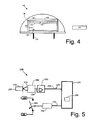
- an external remote disconnect switch 205 also may be used. As is shown in Fig. 4 , the external remote disconnect switch 205 may be positioned apart from the main meter electronics board 110 but in communication with the load 190 or otherwise so as to break the circuit.
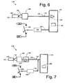
- Fig. 5 shows the operation of the temperature sensor 210 in a temperature monitoring circuit 225.
- the temperature sensor 210 may output an analog voltage signal 230 based upon a temperature 235 of the base 140.
- a comparator, an A/D converter 240, and the like may convert the analog voltage signal 230 to a digital signal 250.
- the digital signal 250 may be received by the processor 120.
- the temperature 235 of the base 140 thus may be compared to a predetermined threshold temperature range 260 or other type of data structure and the like.
- the processor 120 may instruct the remote disconnect switch 200 to open via a disconnect signal 270 such that the utility meter 100 is disconnected from the utility 180 if such threshold temperatures are exceed or other type of predetermined condition is met.
- other parameters may include the rate of temperature change such that the disconnect signal 270 may be provided if an increase of a given number of degrees is detected within a given time frame. Other types of parameters may be used herein.
- An optional sensor buffer circuit 280 also may be used herein.
- an optional switch relay driver 290 also may be used herein.
- the A/D converter 240 may be built into the processor 120. Other components and other configurations may be used herein.
- the processor 120 may be one of those on the main meter electrical board 110 or a separate processor 120 in a stand alone monitoring circuit and the like also may be used. Likewise, the processor 120 may be remote from the utility meter 100 and in communication via a network and the like. As is shown in Fig. 7 , the temperature monitoring circuit 225 may directly drive the switch relay 290 or otherwise drive the remote disconnect switch 200 without notifying the processor 120. Likewise, the processor 120 may be optionally notified in real time or at a later time. The temperature monitoring circuit 225 may be in direct communications with the utility 180 or other source.
- the temperature monitoring circuit 225 of the utility meter 100 described herein thus prevents the base 140 from exceeding threshold temperatures due to the remote disconnect switch 200 or otherwise through the use of the temperature sensor 210. As such, the internal temperatures of the utility meter 100 will remain below the threshold temperatures 260 that may create a possibly dangerous situation.
- the utility meter 100 generally may not be reconnected to the utility 180 until certain types of inspections and/or diagnostics are completed. Reconnection functionality may be greatly varied.
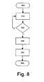
- Fig. 8 shows a flow chart of several method steps that may be used in the temperature monitoring circuit 225.
- the process may begin at step 300.
- the temperature sensor 210 senses the temperature 235 about the base 140 or other location.
- the temperature sensor 210 outputs the analog signal 230 that is converted to the digital signal 250 by the A/D converter 240.
- the digital signal 250 then may be compared to the predetermined threshold temperature range 260 or other type of information at step 320. If the temperature, as represented by the digital signal 250, is below the predetermined threshold range 260, the method may return to step 310 for further temperature readings. If the temperature exceeds the predetermined threshold range 260, the processor 250 may issue the disconnect signal 270 so as to instruct the remote disconnect switch 200 to open at step 330.
- the processor 120 then may report the event at step 340 as desired. Alternatively, the processor 120 may be bypassed such that the remote disconnect switch 200 is directed connected within the temperature monitoring circuit 225. The method may end at step 350.
- the flow chart shown herein is for the purpose of example only. Similar methods may be used herein.
Landscapes
- Physics & Mathematics (AREA)
- General Physics & Mathematics (AREA)
- Arrangements For Transmission Of Measured Signals (AREA)
- Measuring Temperature Or Quantity Of Heat (AREA)
- Indication And Recording Devices For Special Purposes And Tariff Metering Devices (AREA)
- Relay Circuits (AREA)
- Thermally Actuated Switches (AREA)
Applications Claiming Priority (1)
| Application Number | Priority Date | Filing Date | Title |
|---|---|---|---|
| US13/115,145 US8830083B2 (en) | 2011-05-25 | 2011-05-25 | Utility meter with temperature based actuation of a remote disconnect switch |
Publications (2)
| Publication Number | Publication Date |
|---|---|
| EP2527793A1 EP2527793A1 (en) | 2012-11-28 |
| EP2527793B1 true EP2527793B1 (en) | 2015-09-30 |
Family
ID=46419874
Family Applications (1)
| Application Number | Title | Priority Date | Filing Date |
|---|---|---|---|
| EP12168356.9A Active EP2527793B1 (en) | 2011-05-25 | 2012-05-16 | Utility meter with temperature based actuation of a remote disconnect switch |
Country Status (7)
| Country | Link |
|---|---|
| US (1) | US8830083B2 (OSRAM) |
| EP (1) | EP2527793B1 (OSRAM) |
| JP (1) | JP6228357B2 (OSRAM) |
| AU (1) | AU2012203142A1 (OSRAM) |
| BR (1) | BR102012011749A2 (OSRAM) |
| CA (1) | CA2776612C (OSRAM) |
| NZ (1) | NZ600147A (OSRAM) |
Cited By (2)
| Publication number | Priority date | Publication date | Assignee | Title |
|---|---|---|---|---|
| DE102016004696A1 (de) * | 2016-04-20 | 2017-10-26 | Robert M. Seidl | Energiezähler mit Sensoren |
| DE102019129521A1 (de) * | 2019-08-26 | 2021-03-04 | Tdk Electronics Ag | Sensor |
Families Citing this family (28)
| Publication number | Priority date | Publication date | Assignee | Title |
|---|---|---|---|---|
| AU2011101045B4 (en) * | 2011-07-08 | 2012-04-12 | Landis & Gyr Pty Ltd | Method and apparatus for monitoring a condition of a meter |
| US9052351B2 (en) * | 2012-09-19 | 2015-06-09 | Sensus Usa Inc. | Method and apparatus for preventing electricity meter failure |
| US8854217B2 (en) * | 2013-02-13 | 2014-10-07 | Sensus Spectrum Llc | Method and apparatus for operating an electricity meter |
| JP2018504971A (ja) * | 2015-01-28 | 2018-02-22 | アイエムエー ライフ ノース アメリカ インコーポレーテッド | 非侵襲的印刷製品センサを使用するプロセス制御 |
| US10066999B2 (en) * | 2015-09-22 | 2018-09-04 | Elster Solutions, Llc | System and method for monitoring exceptional watt hour meter terminal temperature |
| US10371739B2 (en) | 2015-10-30 | 2019-08-06 | Landis+Gyr Llc | Arrangement for detecting a meter maintenance condition using winding resistance |
| US10511157B2 (en) * | 2016-08-29 | 2019-12-17 | Landis+Gyr Innovations, Inc. | Arc detection in electric meter systems |
| US20180132529A1 (en) * | 2016-11-14 | 2018-05-17 | Rai Strategic Holdings, Inc. | Aerosol delivery device with integrated wireless connectivity for temperature monitoring |
| WO2019027706A1 (en) * | 2017-08-04 | 2019-02-07 | Sensus Spectrum, Llc | METHOD AND SYSTEM FOR HIGH TEMPERATURE DETECTION IN ELECTRICAL METERS |
| US10908198B2 (en) | 2017-08-07 | 2021-02-02 | Landis+Gyr Innovations, Inc. | Determining meter phase using interval voltage measurements |
| US11183878B2 (en) | 2017-08-07 | 2021-11-23 | Landis+Gyr Innovations, Inc. | Maintaining connectivity information for meters and transformers located in a power distribution network |
| US10393791B2 (en) | 2017-09-28 | 2019-08-27 | Landis+Gyr Llc | Detection of deteriorated electrical connections in a meter using temperature sensing and time-variable thresholds |
| US10690519B2 (en) | 2018-02-23 | 2020-06-23 | Landis+Gyr Innovations, Inc. | Meter reading sensor using TMR and hall effect sensors |
| CA3046568C (en) | 2018-07-17 | 2024-02-13 | Neptune Technology Group Inc. | Environmental sensor-based radio transmitter of a utility meter system |
| US10740691B2 (en) | 2018-10-02 | 2020-08-11 | Sense Labs, Inc. | Identifying devices connected to a smart plug |
| US11536754B2 (en) | 2019-08-15 | 2022-12-27 | Landis+Gyr Innovations, Inc. | Electricity meter with fault tolerant power supply |
| US11226357B2 (en) | 2019-09-27 | 2022-01-18 | Landis+Gyr Innovations, Inc. | Electrical arc detection for electric meter socket connections |
| US11245260B2 (en) | 2020-02-25 | 2022-02-08 | Landis+Gyr Innovations, Inc. | Automatic discovery of electrical supply network topology and phase |
| US11429401B2 (en) | 2020-03-04 | 2022-08-30 | Landis+Gyr Innovations, Inc. | Navigating a user interface of a utility meter with touch-based interactions |
| US11646602B2 (en) | 2020-03-11 | 2023-05-09 | Landis+Gyr Innovations, Inc. | Topology and phase detection for electrical supply network |
| US11385074B2 (en) | 2020-03-18 | 2022-07-12 | Landis+Gyr Innovations, Inc. | Programming electric meter global positioning system coordinates using smart device |
| US11536745B2 (en) | 2020-03-18 | 2022-12-27 | Landis+Gyr Innovations, Inc. | Electric meter installation issue detection based on orientation change |
| US11359934B2 (en) | 2020-03-24 | 2022-06-14 | Landis+Gyr Innovations, Inc. | Variable rate monitoring in flow-based metering systems |
| US12181501B2 (en) | 2020-06-09 | 2024-12-31 | Sensus Spectrum, Llc | Systems for detecting temperature and current events in a power grid and related methods |
| CA3121378A1 (en) | 2020-06-09 | 2021-12-09 | Sensus Spectrum, Llc | System for detecting temperature and current events in a power grid and related methods |
| US11402416B2 (en) * | 2020-07-10 | 2022-08-02 | Landis+Gyr Innovations, Inc. | Detecting utility meter orientation based on a temperature gradient of the utility meter |
| US11515725B2 (en) | 2020-09-21 | 2022-11-29 | Landis+Gyr Innovations, Inc. | Autonomous topology validation for electrical supply network |
| WO2023229981A2 (en) * | 2022-05-25 | 2023-11-30 | Sense Labs, Inc. | Electrical meter with dual analog-to-digital converters |
Family Cites Families (8)
| Publication number | Priority date | Publication date | Assignee | Title |
|---|---|---|---|---|
| US4377948A (en) | 1978-11-20 | 1983-03-29 | Tenney Jr Charles M | Differential gas pricing apparatus and method |
| US4833888A (en) * | 1987-01-29 | 1989-05-30 | James M. Kerner | Thermoelectric heating and/or cooling system using liquid for heat exchange |
| JPH05106903A (ja) * | 1991-10-18 | 1993-04-27 | Toshiba Corp | 空気調和機 |
| JPH10201094A (ja) * | 1996-12-28 | 1998-07-31 | Yuzo Takigawa | 電池使用機器の遠隔スイッチ装置 |
| US6847300B2 (en) | 2001-02-02 | 2005-01-25 | Motorola, Inc. | Electric power meter including a temperature sensor and controller |
| US8384558B2 (en) | 2006-10-19 | 2013-02-26 | Itron, Inc. | Extending contact life in remote disconnect applications |
| JP2010019680A (ja) * | 2008-07-10 | 2010-01-28 | Toshiba Corp | 電力量計 |
| GB2506538B (en) * | 2009-07-28 | 2014-07-02 | Skyworks Solutions Inc | Process, voltage and temperature sensor |
-
2011
- 2011-05-25 US US13/115,145 patent/US8830083B2/en active Active
-
2012
- 2012-05-10 CA CA2776612A patent/CA2776612C/en active Active
- 2012-05-16 EP EP12168356.9A patent/EP2527793B1/en active Active
- 2012-05-17 BR BR102012011749-5A patent/BR102012011749A2/pt not_active IP Right Cessation
- 2012-05-22 AU AU2012203142A patent/AU2012203142A1/en not_active Abandoned
- 2012-05-22 NZ NZ600147A patent/NZ600147A/en not_active IP Right Cessation
- 2012-05-23 JP JP2012117209A patent/JP6228357B2/ja active Active
Cited By (2)
| Publication number | Priority date | Publication date | Assignee | Title |
|---|---|---|---|---|
| DE102016004696A1 (de) * | 2016-04-20 | 2017-10-26 | Robert M. Seidl | Energiezähler mit Sensoren |
| DE102019129521A1 (de) * | 2019-08-26 | 2021-03-04 | Tdk Electronics Ag | Sensor |
Also Published As
| Publication number | Publication date |
|---|---|
| US20120299745A1 (en) | 2012-11-29 |
| NZ600147A (en) | 2013-12-20 |
| JP6228357B2 (ja) | 2017-11-08 |
| AU2012203142A1 (en) | 2012-12-13 |
| EP2527793A1 (en) | 2012-11-28 |
| US8830083B2 (en) | 2014-09-09 |
| CA2776612C (en) | 2018-09-04 |
| JP2012247417A (ja) | 2012-12-13 |
| BR102012011749A2 (pt) | 2013-10-22 |
| CA2776612A1 (en) | 2012-11-25 |
Similar Documents
| Publication | Publication Date | Title |
|---|---|---|
| EP2527793B1 (en) | Utility meter with temperature based actuation of a remote disconnect switch | |
| AU2011101045A4 (en) | Method and apparatus for monitoring a condition of a meter | |
| KR101224324B1 (ko) | 수배전반 관리 시스템 및 그 방법 | |
| CN106464012B (zh) | 监视装置以及使用了该监视装置的监视系统 | |
| KR101520758B1 (ko) | 온도와 통전전류 분석방식의 이상 진단 기능을 구비한 배전반 | |
| CN204924486U (zh) | 一种新型无源无线温度监测预警系统 | |
| CN201937244U (zh) | 一种带无线温度测量的微机电动机保护监控装置 | |
| KR101007240B1 (ko) | 전력량계 | |
| CN109347068A (zh) | 一种开关柜电缆头防爆保护装置 | |
| CN208537037U (zh) | 电缆终端头温度故障指示器 | |
| CN109031054B (zh) | 故障电弧检测装置 | |
| CN202167109U (zh) | 一种电气火灾监控系统 | |
| CN105628245A (zh) | 蓄电池表面温度在线检测装置、系统及方法 | |
| CN205539281U (zh) | 一种电网用自动检测仪 | |
| JP2018085600A (ja) | 太陽光発電所のストリング監視装置、携帯端末用アプリケーションおよび太陽光発電所監視システム | |
| CN204142860U (zh) | 具有高压带电显示和温度监测功能的装置 | |
| CN207008019U (zh) | 一种基于无线通信的sf6断路器微水含量在线监测系统 | |
| CN202330595U (zh) | 直流绝缘监察继电器 | |
| CN201805214U (zh) | 带温度测量的微机电动机保护监控装置 | |
| CN216213202U (zh) | 一种具有远程高温报警功能的断路器 | |
| CN213875860U (zh) | 电气预警系统 | |
| KR102092329B1 (ko) | 메탈히터의 소모전류량 감지를 통한 선로이상 경보전송장치 | |
| CN210109261U (zh) | 一种信号防雷自动检测系统 | |
| CN207705722U (zh) | 一种温度遥测通讯功能母线槽 | |
| KR101405020B1 (ko) | 온도 측정 장치 |
Legal Events
| Date | Code | Title | Description |
|---|---|---|---|
| PUAI | Public reference made under article 153(3) epc to a published international application that has entered the european phase |
Free format text: ORIGINAL CODE: 0009012 |
|
| AK | Designated contracting states |
Kind code of ref document: A1 Designated state(s): AL AT BE BG CH CY CZ DE DK EE ES FI FR GB GR HR HU IE IS IT LI LT LU LV MC MK MT NL NO PL PT RO RS SE SI SK SM TR |
|
| AX | Request for extension of the european patent |
Extension state: BA ME |
|
| 17P | Request for examination filed |
Effective date: 20130528 |
|
| RBV | Designated contracting states (corrected) |
Designated state(s): AL AT BE BG CH CY CZ DE DK EE ES FI FR GB GR HR HU IE IS IT LI LT LU LV MC MK MT NL NO PL PT RO RS SE SI SK SM TR |
|
| 17Q | First examination report despatched |
Effective date: 20141008 |
|
| GRAP | Despatch of communication of intention to grant a patent |
Free format text: ORIGINAL CODE: EPIDOSNIGR1 |
|
| INTG | Intention to grant announced |
Effective date: 20150611 |
|
| GRAP | Despatch of communication of intention to grant a patent |
Free format text: ORIGINAL CODE: EPIDOSNIGR1 |
|
| INTG | Intention to grant announced |
Effective date: 20150721 |
|
| GRAS | Grant fee paid |
Free format text: ORIGINAL CODE: EPIDOSNIGR3 |
|
| GRAA | (expected) grant |
Free format text: ORIGINAL CODE: 0009210 |
|
| AK | Designated contracting states |
Kind code of ref document: B1 Designated state(s): AL AT BE BG CH CY CZ DE DK EE ES FI FR GB GR HR HU IE IS IT LI LT LU LV MC MK MT NL NO PL PT RO RS SE SI SK SM TR |
|
| REG | Reference to a national code |
Ref country code: CH Ref legal event code: EP Ref country code: GB Ref legal event code: FG4D |
|
| REG | Reference to a national code |
Ref country code: AT Ref legal event code: REF Ref document number: 752682 Country of ref document: AT Kind code of ref document: T Effective date: 20151015 |
|
| REG | Reference to a national code |
Ref country code: IE Ref legal event code: FG4D |
|
| REG | Reference to a national code |
Ref country code: DE Ref legal event code: R096 Ref document number: 602012011056 Country of ref document: DE |
|
| PG25 | Lapsed in a contracting state [announced via postgrant information from national office to epo] |
Ref country code: NO Free format text: LAPSE BECAUSE OF FAILURE TO SUBMIT A TRANSLATION OF THE DESCRIPTION OR TO PAY THE FEE WITHIN THE PRESCRIBED TIME-LIMIT Effective date: 20151230 Ref country code: GR Free format text: LAPSE BECAUSE OF FAILURE TO SUBMIT A TRANSLATION OF THE DESCRIPTION OR TO PAY THE FEE WITHIN THE PRESCRIBED TIME-LIMIT Effective date: 20151231 Ref country code: FI Free format text: LAPSE BECAUSE OF FAILURE TO SUBMIT A TRANSLATION OF THE DESCRIPTION OR TO PAY THE FEE WITHIN THE PRESCRIBED TIME-LIMIT Effective date: 20150930 Ref country code: LT Free format text: LAPSE BECAUSE OF FAILURE TO SUBMIT A TRANSLATION OF THE DESCRIPTION OR TO PAY THE FEE WITHIN THE PRESCRIBED TIME-LIMIT Effective date: 20150930 Ref country code: LV Free format text: LAPSE BECAUSE OF FAILURE TO SUBMIT A TRANSLATION OF THE DESCRIPTION OR TO PAY THE FEE WITHIN THE PRESCRIBED TIME-LIMIT Effective date: 20150930 |
|
| REG | Reference to a national code |
Ref country code: NL Ref legal event code: MP Effective date: 20150930 |
|
| REG | Reference to a national code |
Ref country code: LT Ref legal event code: MG4D |
|
| REG | Reference to a national code |
Ref country code: AT Ref legal event code: MK05 Ref document number: 752682 Country of ref document: AT Kind code of ref document: T Effective date: 20150930 |
|
| PG25 | Lapsed in a contracting state [announced via postgrant information from national office to epo] |
Ref country code: HR Free format text: LAPSE BECAUSE OF FAILURE TO SUBMIT A TRANSLATION OF THE DESCRIPTION OR TO PAY THE FEE WITHIN THE PRESCRIBED TIME-LIMIT Effective date: 20150930 Ref country code: SE Free format text: LAPSE BECAUSE OF FAILURE TO SUBMIT A TRANSLATION OF THE DESCRIPTION OR TO PAY THE FEE WITHIN THE PRESCRIBED TIME-LIMIT Effective date: 20150930 Ref country code: RS Free format text: LAPSE BECAUSE OF FAILURE TO SUBMIT A TRANSLATION OF THE DESCRIPTION OR TO PAY THE FEE WITHIN THE PRESCRIBED TIME-LIMIT Effective date: 20150930 |
|
| PG25 | Lapsed in a contracting state [announced via postgrant information from national office to epo] |
Ref country code: IT Free format text: LAPSE BECAUSE OF FAILURE TO SUBMIT A TRANSLATION OF THE DESCRIPTION OR TO PAY THE FEE WITHIN THE PRESCRIBED TIME-LIMIT Effective date: 20150930 Ref country code: IS Free format text: LAPSE BECAUSE OF FAILURE TO SUBMIT A TRANSLATION OF THE DESCRIPTION OR TO PAY THE FEE WITHIN THE PRESCRIBED TIME-LIMIT Effective date: 20160130 Ref country code: NL Free format text: LAPSE BECAUSE OF FAILURE TO SUBMIT A TRANSLATION OF THE DESCRIPTION OR TO PAY THE FEE WITHIN THE PRESCRIBED TIME-LIMIT Effective date: 20150930 Ref country code: CZ Free format text: LAPSE BECAUSE OF FAILURE TO SUBMIT A TRANSLATION OF THE DESCRIPTION OR TO PAY THE FEE WITHIN THE PRESCRIBED TIME-LIMIT Effective date: 20150930 Ref country code: ES Free format text: LAPSE BECAUSE OF FAILURE TO SUBMIT A TRANSLATION OF THE DESCRIPTION OR TO PAY THE FEE WITHIN THE PRESCRIBED TIME-LIMIT Effective date: 20150930 Ref country code: EE Free format text: LAPSE BECAUSE OF FAILURE TO SUBMIT A TRANSLATION OF THE DESCRIPTION OR TO PAY THE FEE WITHIN THE PRESCRIBED TIME-LIMIT Effective date: 20150930 Ref country code: SK Free format text: LAPSE BECAUSE OF FAILURE TO SUBMIT A TRANSLATION OF THE DESCRIPTION OR TO PAY THE FEE WITHIN THE PRESCRIBED TIME-LIMIT Effective date: 20150930 |
|
| REG | Reference to a national code |
Ref country code: FR Ref legal event code: PLFP Year of fee payment: 5 |
|
| PG25 | Lapsed in a contracting state [announced via postgrant information from national office to epo] |
Ref country code: PT Free format text: LAPSE BECAUSE OF FAILURE TO SUBMIT A TRANSLATION OF THE DESCRIPTION OR TO PAY THE FEE WITHIN THE PRESCRIBED TIME-LIMIT Effective date: 20160201 Ref country code: AT Free format text: LAPSE BECAUSE OF FAILURE TO SUBMIT A TRANSLATION OF THE DESCRIPTION OR TO PAY THE FEE WITHIN THE PRESCRIBED TIME-LIMIT Effective date: 20150930 Ref country code: PL Free format text: LAPSE BECAUSE OF FAILURE TO SUBMIT A TRANSLATION OF THE DESCRIPTION OR TO PAY THE FEE WITHIN THE PRESCRIBED TIME-LIMIT Effective date: 20150930 Ref country code: RO Free format text: LAPSE BECAUSE OF FAILURE TO SUBMIT A TRANSLATION OF THE DESCRIPTION OR TO PAY THE FEE WITHIN THE PRESCRIBED TIME-LIMIT Effective date: 20150930 |
|
| REG | Reference to a national code |
Ref country code: DE Ref legal event code: R097 Ref document number: 602012011056 Country of ref document: DE |
|
| PLBE | No opposition filed within time limit |
Free format text: ORIGINAL CODE: 0009261 |
|
| STAA | Information on the status of an ep patent application or granted ep patent |
Free format text: STATUS: NO OPPOSITION FILED WITHIN TIME LIMIT |
|
| PG25 | Lapsed in a contracting state [announced via postgrant information from national office to epo] |
Ref country code: DK Free format text: LAPSE BECAUSE OF FAILURE TO SUBMIT A TRANSLATION OF THE DESCRIPTION OR TO PAY THE FEE WITHIN THE PRESCRIBED TIME-LIMIT Effective date: 20150930 Ref country code: BE Free format text: LAPSE BECAUSE OF NON-PAYMENT OF DUE FEES Effective date: 20160531 |
|
| REG | Reference to a national code |
Ref country code: GB Ref legal event code: 732E Free format text: REGISTERED BETWEEN 20160804 AND 20160810 |
|
| 26N | No opposition filed |
Effective date: 20160701 |
|
| PG25 | Lapsed in a contracting state [announced via postgrant information from national office to epo] |
Ref country code: SI Free format text: LAPSE BECAUSE OF FAILURE TO SUBMIT A TRANSLATION OF THE DESCRIPTION OR TO PAY THE FEE WITHIN THE PRESCRIBED TIME-LIMIT Effective date: 20150930 |
|
| PG25 | Lapsed in a contracting state [announced via postgrant information from national office to epo] |
Ref country code: BE Free format text: LAPSE BECAUSE OF FAILURE TO SUBMIT A TRANSLATION OF THE DESCRIPTION OR TO PAY THE FEE WITHIN THE PRESCRIBED TIME-LIMIT Effective date: 20150930 Ref country code: LU Free format text: LAPSE BECAUSE OF FAILURE TO SUBMIT A TRANSLATION OF THE DESCRIPTION OR TO PAY THE FEE WITHIN THE PRESCRIBED TIME-LIMIT Effective date: 20160516 |
|
| REG | Reference to a national code |
Ref country code: CH Ref legal event code: PL |
|
| PG25 | Lapsed in a contracting state [announced via postgrant information from national office to epo] |
Ref country code: LI Free format text: LAPSE BECAUSE OF NON-PAYMENT OF DUE FEES Effective date: 20160531 Ref country code: CH Free format text: LAPSE BECAUSE OF NON-PAYMENT OF DUE FEES Effective date: 20160531 |
|
| REG | Reference to a national code |
Ref country code: IE Ref legal event code: MM4A |
|
| REG | Reference to a national code |
Ref country code: FR Ref legal event code: PLFP Year of fee payment: 6 |
|
| PG25 | Lapsed in a contracting state [announced via postgrant information from national office to epo] |
Ref country code: IE Free format text: LAPSE BECAUSE OF NON-PAYMENT OF DUE FEES Effective date: 20160516 |
|
| REG | Reference to a national code |
Ref country code: FR Ref legal event code: PLFP Year of fee payment: 7 |
|
| PG25 | Lapsed in a contracting state [announced via postgrant information from national office to epo] |
Ref country code: HU Free format text: LAPSE BECAUSE OF FAILURE TO SUBMIT A TRANSLATION OF THE DESCRIPTION OR TO PAY THE FEE WITHIN THE PRESCRIBED TIME-LIMIT; INVALID AB INITIO Effective date: 20120516 Ref country code: SM Free format text: LAPSE BECAUSE OF FAILURE TO SUBMIT A TRANSLATION OF THE DESCRIPTION OR TO PAY THE FEE WITHIN THE PRESCRIBED TIME-LIMIT Effective date: 20150930 Ref country code: CY Free format text: LAPSE BECAUSE OF FAILURE TO SUBMIT A TRANSLATION OF THE DESCRIPTION OR TO PAY THE FEE WITHIN THE PRESCRIBED TIME-LIMIT Effective date: 20150930 |
|
| PG25 | Lapsed in a contracting state [announced via postgrant information from national office to epo] |
Ref country code: MT Free format text: LAPSE BECAUSE OF NON-PAYMENT OF DUE FEES Effective date: 20160531 Ref country code: MC Free format text: LAPSE BECAUSE OF FAILURE TO SUBMIT A TRANSLATION OF THE DESCRIPTION OR TO PAY THE FEE WITHIN THE PRESCRIBED TIME-LIMIT Effective date: 20150930 Ref country code: TR Free format text: LAPSE BECAUSE OF FAILURE TO SUBMIT A TRANSLATION OF THE DESCRIPTION OR TO PAY THE FEE WITHIN THE PRESCRIBED TIME-LIMIT Effective date: 20150930 Ref country code: MK Free format text: LAPSE BECAUSE OF FAILURE TO SUBMIT A TRANSLATION OF THE DESCRIPTION OR TO PAY THE FEE WITHIN THE PRESCRIBED TIME-LIMIT Effective date: 20150930 |
|
| PG25 | Lapsed in a contracting state [announced via postgrant information from national office to epo] |
Ref country code: BG Free format text: LAPSE BECAUSE OF FAILURE TO SUBMIT A TRANSLATION OF THE DESCRIPTION OR TO PAY THE FEE WITHIN THE PRESCRIBED TIME-LIMIT Effective date: 20150930 |
|
| PG25 | Lapsed in a contracting state [announced via postgrant information from national office to epo] |
Ref country code: AL Free format text: LAPSE BECAUSE OF FAILURE TO SUBMIT A TRANSLATION OF THE DESCRIPTION OR TO PAY THE FEE WITHIN THE PRESCRIBED TIME-LIMIT Effective date: 20150930 |
|
| P01 | Opt-out of the competence of the unified patent court (upc) registered |
Effective date: 20230608 |
|
| PGFP | Annual fee paid to national office [announced via postgrant information from national office to epo] |
Ref country code: FR Payment date: 20250310 Year of fee payment: 14 |
|
| PGFP | Annual fee paid to national office [announced via postgrant information from national office to epo] |
Ref country code: GB Payment date: 20250327 Year of fee payment: 14 |
|
| PGFP | Annual fee paid to national office [announced via postgrant information from national office to epo] |
Ref country code: DE Payment date: 20250319 Year of fee payment: 14 |