EP2527699A2 - Check valve for spray nozzle and nozzle tube - Google Patents
Check valve for spray nozzle and nozzle tube Download PDFInfo
- Publication number
- EP2527699A2 EP2527699A2 EP12167835A EP12167835A EP2527699A2 EP 2527699 A2 EP2527699 A2 EP 2527699A2 EP 12167835 A EP12167835 A EP 12167835A EP 12167835 A EP12167835 A EP 12167835A EP 2527699 A2 EP2527699 A2 EP 2527699A2
- Authority
- EP
- European Patent Office
- Prior art keywords
- tube
- check valve
- valve seat
- nozzle
- shut
- Prior art date
- Legal status (The legal status is an assumption and is not a legal conclusion. Google has not performed a legal analysis and makes no representation as to the accuracy of the status listed.)
- Granted
Links
Images
Classifications
-
- F—MECHANICAL ENGINEERING; LIGHTING; HEATING; WEAPONS; BLASTING
- F16—ENGINEERING ELEMENTS AND UNITS; GENERAL MEASURES FOR PRODUCING AND MAINTAINING EFFECTIVE FUNCTIONING OF MACHINES OR INSTALLATIONS; THERMAL INSULATION IN GENERAL
- F16K—VALVES; TAPS; COCKS; ACTUATING-FLOATS; DEVICES FOR VENTING OR AERATING
- F16K17/00—Safety valves; Equalising valves, e.g. pressure relief valves
- F16K17/02—Safety valves; Equalising valves, e.g. pressure relief valves opening on surplus pressure on one side; closing on insufficient pressure on one side
- F16K17/04—Safety valves; Equalising valves, e.g. pressure relief valves opening on surplus pressure on one side; closing on insufficient pressure on one side spring-loaded
-
- F—MECHANICAL ENGINEERING; LIGHTING; HEATING; WEAPONS; BLASTING
- F16—ENGINEERING ELEMENTS AND UNITS; GENERAL MEASURES FOR PRODUCING AND MAINTAINING EFFECTIVE FUNCTIONING OF MACHINES OR INSTALLATIONS; THERMAL INSULATION IN GENERAL
- F16K—VALVES; TAPS; COCKS; ACTUATING-FLOATS; DEVICES FOR VENTING OR AERATING
- F16K15/00—Check valves
- F16K15/02—Check valves with guided rigid valve members
- F16K15/08—Check valves with guided rigid valve members shaped as rings
-
- B—PERFORMING OPERATIONS; TRANSPORTING
- B05—SPRAYING OR ATOMISING IN GENERAL; APPLYING FLUENT MATERIALS TO SURFACES, IN GENERAL
- B05B—SPRAYING APPARATUS; ATOMISING APPARATUS; NOZZLES
- B05B1/00—Nozzles, spray heads or other outlets, with or without auxiliary devices such as valves, heating means
- B05B1/30—Nozzles, spray heads or other outlets, with or without auxiliary devices such as valves, heating means designed to control volume of flow, e.g. with adjustable passages
- B05B1/3006—Nozzles, spray heads or other outlets, with or without auxiliary devices such as valves, heating means designed to control volume of flow, e.g. with adjustable passages the controlling element being actuated by the pressure of the fluid to be sprayed
-
- F—MECHANICAL ENGINEERING; LIGHTING; HEATING; WEAPONS; BLASTING
- F16—ENGINEERING ELEMENTS AND UNITS; GENERAL MEASURES FOR PRODUCING AND MAINTAINING EFFECTIVE FUNCTIONING OF MACHINES OR INSTALLATIONS; THERMAL INSULATION IN GENERAL
- F16K—VALVES; TAPS; COCKS; ACTUATING-FLOATS; DEVICES FOR VENTING OR AERATING
- F16K1/00—Lift valves or globe valves, i.e. cut-off apparatus with closure members having at least a component of their opening and closing motion perpendicular to the closing faces
- F16K1/32—Details
- F16K1/34—Cutting-off parts, e.g. valve members, seats
- F16K1/36—Valve members
- F16K1/38—Valve members of conical shape
-
- F—MECHANICAL ENGINEERING; LIGHTING; HEATING; WEAPONS; BLASTING
- F16—ENGINEERING ELEMENTS AND UNITS; GENERAL MEASURES FOR PRODUCING AND MAINTAINING EFFECTIVE FUNCTIONING OF MACHINES OR INSTALLATIONS; THERMAL INSULATION IN GENERAL
- F16K—VALVES; TAPS; COCKS; ACTUATING-FLOATS; DEVICES FOR VENTING OR AERATING
- F16K15/00—Check valves
- F16K15/02—Check valves with guided rigid valve members
- F16K15/08—Check valves with guided rigid valve members shaped as rings
- F16K15/12—Springs for ring valves
-
- F—MECHANICAL ENGINEERING; LIGHTING; HEATING; WEAPONS; BLASTING
- F16—ENGINEERING ELEMENTS AND UNITS; GENERAL MEASURES FOR PRODUCING AND MAINTAINING EFFECTIVE FUNCTIONING OF MACHINES OR INSTALLATIONS; THERMAL INSULATION IN GENERAL
- F16K—VALVES; TAPS; COCKS; ACTUATING-FLOATS; DEVICES FOR VENTING OR AERATING
- F16K17/00—Safety valves; Equalising valves, e.g. pressure relief valves
- F16K17/02—Safety valves; Equalising valves, e.g. pressure relief valves opening on surplus pressure on one side; closing on insufficient pressure on one side
- F16K17/04—Safety valves; Equalising valves, e.g. pressure relief valves opening on surplus pressure on one side; closing on insufficient pressure on one side spring-loaded
- F16K17/0493—Safety valves; Equalising valves, e.g. pressure relief valves opening on surplus pressure on one side; closing on insufficient pressure on one side spring-loaded with a spring other than a helicoidal spring
-
- F—MECHANICAL ENGINEERING; LIGHTING; HEATING; WEAPONS; BLASTING
- F16—ENGINEERING ELEMENTS AND UNITS; GENERAL MEASURES FOR PRODUCING AND MAINTAINING EFFECTIVE FUNCTIONING OF MACHINES OR INSTALLATIONS; THERMAL INSULATION IN GENERAL
- F16K—VALVES; TAPS; COCKS; ACTUATING-FLOATS; DEVICES FOR VENTING OR AERATING
- F16K27/00—Construction of housing; Use of materials therefor
- F16K27/02—Construction of housing; Use of materials therefor of lift valves
- F16K27/0209—Check valves or pivoted valves
-
- F—MECHANICAL ENGINEERING; LIGHTING; HEATING; WEAPONS; BLASTING
- F16—ENGINEERING ELEMENTS AND UNITS; GENERAL MEASURES FOR PRODUCING AND MAINTAINING EFFECTIVE FUNCTIONING OF MACHINES OR INSTALLATIONS; THERMAL INSULATION IN GENERAL
- F16K—VALVES; TAPS; COCKS; ACTUATING-FLOATS; DEVICES FOR VENTING OR AERATING
- F16K51/00—Other details not peculiar to particular types of valves or cut-off apparatus
-
- B—PERFORMING OPERATIONS; TRANSPORTING
- B05—SPRAYING OR ATOMISING IN GENERAL; APPLYING FLUENT MATERIALS TO SURFACES, IN GENERAL
- B05B—SPRAYING APPARATUS; ATOMISING APPARATUS; NOZZLES
- B05B15/00—Details of spraying plant or spraying apparatus not otherwise provided for; Accessories
- B05B15/40—Filters located upstream of the spraying outlets
Definitions
- the water stop valves or check valves shown there have a tubular valve housing, in which a conical shut-off body is arranged to be movable in the longitudinal direction of the tubular valve housing.
- the valve body is biased by a compression spring towards a valve seat.
- the tubular valve housing is part of a nozzle tube and the valve seat is provided on a filter component.
- the filter component then forms an extension of the tubular valve housing, which in turn is provided at the opposite end with a spray nozzle.
- a guide tube is provided within the corrugated tube, wherein the guide tube forms part of a fluid channel through the check valve.
- Such arcuate slots can be arranged concentrically surrounding the valve seat and provide a low flow resistance compared to a circular bore, since a larger free flow cross-section can be realized and the flow must be deflected less strongly.
- the gradual leakage of the streamline body provides for low flow resistance and calming of the flow.
- the streamline body thereby tapers in the region of the valve seat, then widens again to this taper and then gradually runs out to a tip end.
- the streamline body advantageously has a tip directed against the flow, from which the streamline body can then expand conically.
- the flow line body is advantageously connected by means of individual webs with a housing of the check valve, wherein these webs form part of a valve seat disc, for example. In the region of the valve seat disc, the streamline body can then run parallel to the central longitudinal axis of the check valve. Overall, the streamline body thus has, viewed in the direction of flow, from a first point first conically widening shape.
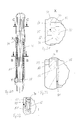
- a jet straightener 34 Downstream of the corrugated tube 32, a jet straightener 34 is arranged.
- the jet straightener 34 is integrally formed with the nozzle tube 10 and has a plurality of radially inwardly extending flow guide surfaces.
- the flow guide surfaces run towards a central longitudinal axis 36 of the nozzle tube 10 and are arranged parallel to this central longitudinal axis 36.
- the beam director 34 is for this reason also referred to as a soulless beam judge.
- a fluid channel 38 Downstream of the Strahlrichters 34, a fluid channel 38 connects with a constant cross-section. This fluid channel 38 then merges into a nozzle mouthpiece 40, which tapers the free cross section and which has an outlet opening 42.
- the nozzle mouthpiece 40 is held by means of the union nut 12 on the nozzle tube 10.
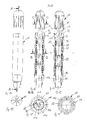
- the presentation of the Fig. 20 shows one Fig. 16 comparable representation, wherein in the range of the details X and Y, a distance in the radial direction between an inner periphery of the nozzle tube 60 and the shut-off body 74 and the guide tube 78 has been exaggerated. This is to clarify that fluid can penetrate both into the area between the inside of the nozzle tube 60 and the corrugated tube 76 and in the region between the inside of the corrugated tube 76 and the guide tube 78.
Landscapes
- Engineering & Computer Science (AREA)
- General Engineering & Computer Science (AREA)
- Mechanical Engineering (AREA)
- Nozzles (AREA)
- Check Valves (AREA)
- Safety Valves (AREA)
- Details Of Valves (AREA)
- Containers And Packaging Bodies Having A Special Means To Remove Contents (AREA)
Abstract
Description
Die Erfindung betrifft ein Rückschlagventil für eine Sprühdüse mit einem Ventilgehäuse, einem Absperrkörper und einem Ventilsitz, wobei der Absperrkörper wenigstens in einer Längsrichtung des Ventilgehäuses beweglich angeordnet ist. Die Erfindung betrifft auch ein Düsenrohr mit Filter zum Einstecken in eine Zuführleitung.The invention relates to a check valve for a spray nozzle with a valve housing, a shut-off body and a valve seat, wherein the shut-off body is arranged to be movable at least in a longitudinal direction of the valve housing. The invention also relates to a nozzle tube with filter for insertion into a supply line.
Aus dem Produktprogramm der Anmelderin Lechler GmbH ist ein sogenanntes Water Stop Valve für Entzunderungsdüsen bekannt, siehe Prospekt WSV "Water Stop Valve for Scalemaster Nozzles", Lechler GmbH, 1/07. Die dort gezeigten Wasserstoppventile oder Rückschlagventile weisen ein rohrförmiges Ventilgehäuse auf, in dem ein kegelförmiger Absperrkörper in Längsrichtung des rohrförmigen Ventilgehäuses beweglich angeordnet ist. Der Ventilkörper wird mittels einer Druckfeder in Richtung auf einen Ventilsitz vorgespannt. Das rohrförmige Ventilgehäuse ist Bestandteil eines Düsenrohres und der Ventilsitz ist an einem Filterbauteil vorgesehen. Das Filterbauteil bildet dann eine Verlängerung des rohrförmigen Ventilgehäuses, das wiederum am gegenüberliegenden Ende mit einer Sprühdüse versehen ist. Das gesamte Düsenrohr einschließlich Sprühdüse wird dann teilweise in eine Zuführleitung bzw. in einen Anschweißnippel eines Spritzbalkens eingeschoben, so dass das Filterbauteil innerhalb des Spritzbalkens angeordnet ist und über die Sprühdüse Sprühflüssigkeit aus der Zuführleitung in die Umgebung gelangen kann. Solche bekannten Rückschlagventile und Düsenrohre werden bei der Entzunderung von heißen Metalloberflächen, insbesondere in Walzwerken, eingesetzt und sollen verhindern, dass nach Absenken des Fluiddruckes noch wesentliche Fluidmengen aus der Sprühdüse austreten.From the product program of the applicant Lechler GmbH a so-called Water Stop Valve for descaling nozzles is known, see brochure WSV "Water Stop Valve for Scalemaster Nozzles", Lechler GmbH, 1/07. The water stop valves or check valves shown there have a tubular valve housing, in which a conical shut-off body is arranged to be movable in the longitudinal direction of the tubular valve housing. The valve body is biased by a compression spring towards a valve seat. The tubular valve housing is part of a nozzle tube and the valve seat is provided on a filter component. The filter component then forms an extension of the tubular valve housing, which in turn is provided at the opposite end with a spray nozzle. The entire nozzle tube including spray nozzle is then partially into a supply line or inserted into a weld nipple of a spray bar, so that the filter component is disposed within the spray bar and can get over the spray nozzle spray liquid from the supply into the environment. Such known check valves and nozzle tubes are used in the descaling of hot metal surfaces, in particular in rolling mills, and are intended to prevent significant amounts of fluid from escaping from the spray nozzle after the fluid pressure has been lowered.
Mit der Erfindung sollen ein verbessertes Rückschlagventil und ein verbessertes Düsenrohr bereitgestellt werden.With the invention, an improved check valve and an improved nozzle tube are provided.
Erfindungsgemäß ist hierzu ein Rückschlagventil für eine Sprühdüse mit einem Ventilgehäuse, einem Absperrkörper und einem Ventilsitz vorgesehen, wobei der Absperrkörper wenigstens in einer Längsrichtung des Ventilgehäuses beweglich angeordnet ist, bei dem der Absperrkörper mittels eines parallel zur Längsrichtung angeordneten Wellrohres mit dem Ventilgehäuse verbunden ist, wobei der Absperrkörper mittels einer Federwirkung des Wellrohres in Richtung auf den Ventilsitz vorgespannt ist.According to the invention, a check valve for a spray nozzle with a valve body, a shut-off body and a valve seat is provided, wherein the shut-off body is arranged to be movable at least in a longitudinal direction of the valve housing, wherein the shut-off is connected by means of a parallel to the longitudinal direction corrugated pipe with the valve housing, wherein the shut-off is biased by a spring action of the corrugated tube in the direction of the valve seat.
Mittels eines Wellrohres kann der Absperrkörper in Längsrichtung des beispielsweise rohrförmigen Ventilgehäuses beweglich mit diesem verbunden werden. Eine separate Druckfeder kann eingespart werden und das erfindungsgemäße Rückschlagventil kann vereinfacht werden.By means of a corrugated tube, the shut-off body can be connected in the longitudinal direction of the example tubular valve housing movable with this. A separate compression spring can be saved and the check valve according to the invention can be simplified.
In Weiterbildung der Erfindung ist das Wellrohr sowohl auf seiner radial innen liegenden Innenseite als auch auf seiner radial außen liegenden Außenseite wenigstens im geöffneten Zustand des Rückschlagventils mit unter Druck stehendem, zu versprühendem Fluid beaufschlagt.In a further development of the invention, the corrugated tube is acted upon both on its radially inner side lying on its radially outer side at least in the open state of the check valve with pressurized, to be sprayed fluid.
Auf diese Weise kann auch bei extrem hohen Drücken des zu versprühenden Fluids von mehreren 100 bar sichergestellt werden, dass das Wellrohr nicht seitlich ausgelenkt wird, wodurch eine durch das Wellrohr auf den Absperrkörper ausgeübte Vorspannkraft verändert werden könnte. Vielmehr heben sich der radial innen und radial außen auf das Wellrohr wirkende Druck gegenseitig auf, so dass das Wellrohr in und entgegen der Absperrrichtung frei beweglich bleibt. Um diese beidseitige Druckbeaufschlagung zu realisieren, kann zwischen dem Absperrkörper und einer Innenseite des Düsenrohres ein erster Strömungskanal ausgebildet sein, der die radial außen liegende Seite des Wellrohres mit unter Druck stehendem Fluid beaufschlagt. Am stromabwärts gelegenen Ende des Leitrohres kann ein Strömungskanal zwischen der Innenseite des Düsenrohres und dem Leitrohr ausgebildet sein, um die radial innen liegende Seite des Wellrohres mit unter Druck stehendem Fluid zu beaufschlagen. Alternativ bildet das Wellrohr mit seiner radial innen liegenden Seite einen Teil des Strömungskanals.In this way it can be ensured even at extremely high pressures of the fluid to be sprayed of several 100 that the corrugated pipe is not deflected laterally, whereby a biasing force exerted by the corrugated tube on the shut-off body could be changed. Rather, the radially inwardly and radially outwardly acting on the corrugated pipe pressure cancel each other, so that the corrugated pipe remains freely movable in and against the Absperrrichtung. In order to realize this two-sided pressurization, may be formed between the shut-off and an inner side of the nozzle tube, a first flow channel, which acts on the radially outer side of the corrugated pipe with pressurized fluid. At the downstream end of the guide tube, a flow channel between the inside of the nozzle tube and the guide tube may be formed to pressurize the radially inner side of the corrugated tube with pressurized fluid. Alternatively, the corrugated tube with its radially inner side forms part of the flow channel.
In Weiterbildung der Erfindung ist innerhalb des Wellrohres ein Leitrohr vorgesehen, wobei das Leitrohr Teil eines Fluidkanals durch das Rückschlagventil bildet.In a further development of the invention, a guide tube is provided within the corrugated tube, wherein the guide tube forms part of a fluid channel through the check valve.
Durch Vorsehen eines Leitrohres innerhalb des Wellrohres, wobei das Leitrohr vorteilhafterweise kreiszylinderförmig mit glatten Wänden ausgebildet ist, kann sichergestellt werden, dass lediglich ein geringer Strömungsverlust im Rückschlagventil auftritt, da das Leitrohr und nicht das Wellrohr Teil des Strömungskanals bilden und dadurch Turbulenzen verringert werden. Trotz Vorsehen des Leitrohres kann ein großer freier Querschnitt für durchströmendes Fluid realisiert werden. Das Leitrohr weist vorteilhafterweise einen konstanten Durchmesser auf.By providing a guide tube within the corrugated tube, wherein the guide tube is advantageously formed circular cylindrical shape with smooth walls, it can be ensured that only a small flow loss occurs in the check valve, since the guide tube and not the corrugated pipe form part of the flow channel, thereby reducing turbulence. Despite providing the guide tube, a large free cross-section can be realized for fluid flowing through. The guide tube advantageously has a constant diameter.
In Weiterbildung der Erfindung ist das Leitrohr an einem Ende fest mit dem Absperrkörper verbunden und am anderen Ende relativ zum Ventilgehäuse verschiebbar gelagert.In a further development of the invention, the guide tube is connected at one end fixed to the shut-off and slidably mounted at the other end relative to the valve housing.
Auf diese Weise kann zwischen den beweglichen Absperrkörper und dem gegenüberliegenden, beweglichen Ende des Leitrohres ein durchgehender Fluidkanal mit glatter Wand realisiert werden. Je nach Wanddicke des Leitrohres liegt zwischen dem beweglichen Ende des Leitrohres und dem Düsengehäuse nur ein Absatz in Höhe der Wandstärke des Leitrohres vor. Gegenüber dem Vorsehen einer Schraubenfeder bietet ein Wellrohr den Vorteil, weniger Platz als eine Schraubenfeder mit gleicher Vorspannkraft zu benötigen. Der freie Strömungsquerschnitt innerhalb des Leitrohres kann dadurch größer ausgeführt werden und ein geringerer Strömungsverlust wird realisiert.In this way, a continuous fluid channel with a smooth wall can be realized between the movable shut-off body and the opposite, movable end of the guide tube. Depending on the wall thickness of the guide tube is between the movable end of the guide tube and the nozzle housing only a paragraph in the amount of wall thickness of the guide tube before. Compared with the provision of a helical spring offers a corrugated tube has the advantage of requiring less space than a coil spring with the same biasing force. The free flow cross section within the guide tube can thereby be made larger and a lower flow loss is realized.
In Weiterbildung der Erfindung ist der Absperrkörper in Durchflussrichtung gesehen an einem stromaufwärts gelegenen Ende des Wellrohres angeordnet.In a further development of the invention, the shut-off body is arranged in the direction of flow at an upstream end of the corrugated pipe.
Auf diese Weise kann stromabwärts des Absperrkörpers eine lange Beruhigungsstrecke für die Strömung angeordnet werden, die zu einer Verringerung von Turbulenzen und damit einem geringen Strömungswiderstand beiträgt. Gerade bei sehr hohen Fluiddrücken, wie sie für Entzunderungsdüsen verwendet werden, kann dadurch auch mit der stromabwärts des Absperrkörpers und stromabwärts des Wellrohres angeordneten Sprühdüse ein besseres Sprühbild erzielt werden.In this way, a long calming section for the flow can be arranged downstream of the shut-off body, which contributes to a reduction of turbulence and thus a low flow resistance. Especially at very high fluid pressures, as used for Entzunderungsdüsen, thereby a better spray pattern can be achieved with the arranged downstream of the shut-off and downstream of the corrugated tube spray nozzle.
In Weiterbildung der Erfindung ist der Absperrkörper ringförmig und der Ventilsitz wenigstens abschnittsweise kegelstumpfförmig ausgebildet, wobei der Absperrkörper in einer Schließstellung auf einer Kegelmantelfläche des Ventilsitzes anliegt.In a further development of the invention, the shut-off body is annular and the valve seat at least partially frusto-conical, wherein the shut-off body rests in a closed position on a conical surface of the valve seat.
Mittels eines ringförmigen Absperrkörpers und eines kegelstumpfförmigen Ventilsitzes lässt sich eine gute Dichtwirkung bei geringem Anpressdruck erzielen. Vor allem ist aber auch eine strömungsgünstige Gestaltung des Ventilsitzes möglich. Der ringförmige Absperrkörper kann an den Innendurchmesser des Wellrohres angepasst werden, so dass am Übergang zwischen ringförmigem Absperrkörper und Wellkörper keine Verringerung des freien Strömungsquerschnitts auftritt.By means of an annular shut-off body and a frusto-conical valve seat can be achieved a good sealing effect with low contact pressure. Above all, however, a streamlined design of the valve seat is possible. The annular shut-off body can be adapted to the inner diameter of the corrugated pipe, so that no reduction of the free flow cross-section occurs at the transition between the annular shut-off body and corrugated body.
In Weiterbildung der Erfindung ist der Ventilsitz an einer Ventilsitzscheibe vorgesehen, die in einen Fluidkkanal des Rückschlagventils eingesetzt und mit wenigstens einem Durchlasskanal versehen ist.In a further development of the invention, the valve seat is provided on a valve seat disc which is inserted into a fluid channel of the check valve and provided with at least one passage channel.
Durch diese Maßnahmen wird die Herstellbarkeit des erfindungsgemäßen Rückschlagventils erleichtert, da die Ventilsitzscheibe in einfacher Weise in ein rohrförmiges Ventilgehäuse eingesetzt werden kann.By these measures, the manufacturability of the check valve according to the invention is facilitated because the valve seat disc can be used in a simple manner in a tubular valve housing.
In Weiterbildung der Erfindung ist der wenigstens eine Durchlasskanal mittels einer Durchgangsbohrung und/oder einer Nut in der Ventilsitzscheibe ausgebildet. Vorteilhafterweise ist der wenigstens eine Durchlasskanal als bogenförmiges Langloch in der Ventilsitzscheibe ausgebildet.In a further development of the invention, the at least one passage channel is formed by means of a through hole and / or a groove in the valve seat disc. Advantageously, the at least one passage channel is formed as a curved slot in the valve seat disc.
Solche bogenförmigen Langlöcher können den Ventilsitz konzentrisch umgebend angeordnet sein und stellen einen geringen Strömungswiderstand gegenüber einer kreisrunden Bohrung bereit, da ein größerer freier Strömungsquerschnitt realisierbar ist und die Strömung weniger stark umgelenkt werden muss.Such arcuate slots can be arranged concentrically surrounding the valve seat and provide a low flow resistance compared to a circular bore, since a larger free flow cross-section can be realized and the flow must be deflected less strongly.
In Weiterbildung der Erfindung ist der Ventilsitz Teil eines Stromlinienkörpers.In a further development of the invention, the valve seat is part of a streamline body.
Auf diese Weise kann ein geringerer Strömungswiderstand erzielt werden und auch ein Sprühbild einer mit der durch das Rückschlagventil geleiteten Flüssigkeit beaufschlagten Düse kann wesentlich verbessert werden. Gerade bei den hohen Fluiddrücken, mit denen Entzunderungsdüsen beaufschlagt werden, ist dies von erheblichem Vorteil.In this way, a lower flow resistance can be achieved and also a spray pattern with the through the check valve guided liquid acted upon nozzle can be significantly improved. This is a considerable advantage, especially at the high fluid pressures with which descaling nozzles are applied.
In Weiterbildung der Erfindung ist der Absperrkörper ringförmig ausgebildet und der Stromlinienkörper erstreckt sich durch den Absperrkörper hindurch.In a further development of the invention, the shut-off body is annular and the streamline body extends through the shut-off body.
Durch diese Maßnahme kann bei geöffnetem Rückschlagventil das Fluid durch den ringförmigen Absperrkörper hindurch und in das Leitrohr geführt werden. Gerade am kritischen Übergang zwischen Absperrkörper und dem danach folgenden Stromlinienkörper bzw. dem Leitrohr kann die Strömung dadurch merklich beruhigt werden.By this measure, with the check valve open, the fluid can be passed through the annular shut-off body and into the guide tube. Especially at the critical transition between shut-off and the subsequent streamline body or the guide tube, the flow can be noticeably calmed.
In Weiterbildung der Erfindung verjüngt sich, in Strömungsrichtung gesehen, der Stromlinienkörper im Bereich des Ventilsitzes und erweitert sich stromabwärts des Ventilsitzes wieder.In a further development of the invention, seen in the flow direction, the streamline body tapers in the region of the valve seat and expands downstream of the valve seat again.
Überraschenderweise kann die Strömung in dem Strömungskanal stromabwärts des Absperrkörpers bzw. Ventilsitzes merklich beruhigt werden, wenn der Stromlinienkörper sich anschließend an die Verjüngung, die im Bereich des Ventilsitzes angeordnet ist, wieder erweitert. Durch eine solche Erweiterung nach der Verjüngung des Ventilsitzes wird die Strömung gegen die Innenwand des Strömungskanals bzw. des Leitrohres gedrückt, wodurch überraschenderweise ein geringer Strömungswiderstand und eine Beruhigung der Strömung erzielt werden.Surprisingly, the flow in the flow channel downstream of the shut-off or valve seat can be noticeably calmed when the streamline body expands again following the taper which is arranged in the region of the valve seat. By such an extension after the tapering of the valve seat, the flow is pressed against the inner wall of the flow channel or the guide tube, which surprisingly a low flow resistance and a calming of the flow can be achieved.
In Weiterbildung der Erfindung verjüngt sich, in Strömungsrichtung gesehen, anschließend an die Erweiterung, die stromabwärts des Ventilsitzes angeordnet ist, der Stromlinienkörper wieder bis zu einer Endspitze.In a further development of the invention, viewed in the direction of flow, following the extension, which is arranged downstream of the valve seat, the streamline body tapers again up to an end tip.
Das allmähliche Auslaufen des Stromlinienkörpers sorgt für einen geringen Strömungswiderstand und eine Beruhigung der Strömung. Der Stromlinienkörper verjüngt sich dadurch im Bereich des Ventilsitzes, erweitert sich anschließend an diese Verjüngung wieder und läuft dann allmählich bis zu einer Endspitze aus. Stromaufwärts des Ventilsitzes weist der Stromlinienkörper vorteilhafterweise eine gegen die Strömung gerichtete Spitze auf, von der ausgehend sich der Stromlinienkörper dann kegelförmig erweitern kann. Der Stromlinienkörper ist vorteilhafterweise mittels einzelner Stege mit einem Gehäuse des Rückschlagventils verbunden, wobei diese Stege beispielsweise Teil einer Ventilsitzscheibe bilden. Im Bereich der Ventilsitzscheibe kann der Stromlinienkörper dann parallel zur Mittellängsachse des Rückschlagventils verlaufen. Insgesamt weist der Stromlinienkörper damit eine, in Strömungsrichtung gesehen, sich von einer Spitze zunächst erst kegelförmig erweiternde Form auf. Anschließend verlaufen Außenwände des Stromlinienkörpers im Bereich der Ventilsitzscheibe und deren Durchgangskanälen im Wesentlichen parallel zu einer Mittellängsachse. Anschließend an diesen parallel zur Mittellängsachse verlaufenden Bereich verjüngt sich der Stromlinienkörper, um in diesem Bereich den Ventilsitz auszubilden. Der Ventilsitz ist durch einen sich verjüngenden Bereich gebildet. Nach Durchlaufen eines lokal geringsten Durchmessers erweitert sich der Stromlinienkörper wieder. Dieser Übergang von der Verjüngung zu der erneuten Erweiterung ist vorteilhafterweise ausgerundet ausgebildet. Anschließend an die Erweiterung folgt dann wieder eine erneute Verjüngung des Stromlinienkörpers bis zu einer Endspitze. Auch dieser Übergang von der Erweiterung zu der erneuten Verjüngung ist vorteilhafterweise gerundet ausgebildet. Die Endspitze kann dann allmählich auslaufen und insgesamt etwa die Hälfte der Länge des gesamten Stromlinienkörpers einnehmen.The gradual leakage of the streamline body provides for low flow resistance and calming of the flow. The streamline body thereby tapers in the region of the valve seat, then widens again to this taper and then gradually runs out to a tip end. Upstream of the valve seat, the streamline body advantageously has a tip directed against the flow, from which the streamline body can then expand conically. The flow line body is advantageously connected by means of individual webs with a housing of the check valve, wherein these webs form part of a valve seat disc, for example. In the region of the valve seat disc, the streamline body can then run parallel to the central longitudinal axis of the check valve. Overall, the streamline body thus has, viewed in the direction of flow, from a first point first conically widening shape. Subsequently, outer walls of the streamline body extend in the region of the valve seat disk and the passage channels thereof substantially parallel to a central longitudinal axis. Subsequent to this area running parallel to the central longitudinal axis, the streamline body tapers to form the valve seat in this area. The valve seat is formed by a tapered region. After passing through a locally smallest diameter, the streamline body widens again. This transition from the taper to the new extension is advantageously rounded. Subsequent to the extension follows again a rejuvenation of the streamline body up to a final peak. Also, this transition from the extension to the rejuvenation is advantageously rounded. The end tip may then gradually leak and occupy a total of about half the length of the entire streamline body.
Das der Erfindung zugrundeliegende Problem wird auch durch ein Düsenrohr mit Filter zum Einstecken in eine Zuführleitung gelöst, das mit einem erfindungsgemäßen Rückschlagventil versehen ist.The problem underlying the invention is also solved by a nozzle tube with filter for insertion into a supply line, which is provided with a check valve according to the invention.
Bei einem solchen Düsenrohr kann innerhalb des Wellrohres ein Leitrohr vorgesehen sein und der Ventilsitz kann Teil eines Stromlinienkörpers sein, wobei in Weiterbildung der Erfindung ein Strahlrichter stromabwärts des Stromlinienkörpers in dem Leitrohr angeordnet ist.In such a nozzle tube, a guide tube may be provided within the corrugated tube and the valve seat may be part of a streamline body, wherein in a further development of the invention, a jet straightener downstream of the streamline body is arranged in the guide tube.
Durch Vorsehen eines Strahlrichters können innerhalb des Leitrohres möglicherweise noch nicht vollständig abgeklungene Turbulenzen weiter vermindert werden und es kann gerade bei den hohen Fluiddrücken, die bei Entzunderungsdüsen verwendet werden, ein gutes und zeitlich konstantes Sprühbild mit einer am Düsenrohr angeordneten Sprühdüse erzielt werden.By providing a jet straightener, turbulence that has not yet completely subsided within the guide tube may be further reduced, and a good and temporally constant spray pattern with a spray nozzle arranged at the nozzle tube can be achieved, especially at the high fluid pressures which are used in descaler nozzles.
In Weiterbildung der Erfindung weist der Strahlrichter mehrere Strömungsleitflächen auf, die sich in radialer Richtung auf eine Mittellängsachse des Strahlrichters zu erstrecken, wobei ein die Mittellängsachse unmittelbar umgebender Bereich frei von Einbauten ist.In a further development of the invention, the jet straightener has a plurality of flow guide surfaces which extend in the radial direction onto a central longitudinal axis of the jet director, wherein an area immediately surrounding the central longitudinal axis is free of internals.
Mittels eines solchen Strahlrichters lässt sich eine gute Richtwirkung der Strömung bei geringem Strömungswiderstand erreichen.By means of such a jet straightener, a good directivity of the flow can be achieved with low flow resistance.
In Weiterbildung der Erfindung ist stromabwärts des Strahlrichters ein Fluidkanal mit konstantem Querschnitt angeordnet.In a further development of the invention, a fluid channel with a constant cross section is arranged downstream of the jet straightener.
Ein solcher Fluidkanal mit konstantem Querschnitt stromabwärts des Strahlrichters und stromaufwärts einer Sprühdüse hat sich in Bezug auf einen geringen Strömungswiderstand und ein gutes Sprühbild als vorteilhaft erwiesen.Such a constant cross-section fluid passage downstream of the jet director and upstream of a spray nozzle has been found to be advantageous in terms of low flow resistance and good spray pattern.
Weitere Merkmale und Vorteile der Erfindung ergeben sich aus den Ansprüchen und der nachfolgenden Beschreibung bevorzugter Ausführungsformen der Erfindung im Zusammenhang mit den Zeichnungen. Einzelmerkmale der unterschiedlichen Ausführungsformen lassen sich dabei in beliebiger Weise miteinander kombinieren, ohne den Rahmen der Erfindung zu überschreiten. In den Zeichnungen zeigen:
- Fig. 1
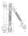
- eine Seitenansicht eines erfindungsgemäßen Düsenrohres gemäß einer bevorzugten Ausführungsform der Erfindung mit daran angeordneter Sprühdüse,
- Fig. 2
- eine Ansicht auf die Schnittebene A-A der
Fig. 2 , - Fig. 3
- eine isometrische Darstellung des gemäß
Fig. 2 geschnittenen Düsenrohres, - Fig. 4
- eine Ansicht des Düsenrohres der
Fig. 1 ohne Sprühdüse von hinten, - Fig. 5
- eine Seitenansicht des Düsenrohres der
Fig. 4 , - Fig. 6
- eine Ansicht auf die Schnittebene A-A aus
Fig. 5 , - Fig. 7
- eine isometrische Darstellung des gemäß
Fig. 6 geschnittenen Düsenrohres, - Fig. 8
- eine Ansicht auf die Schnittebene B-B in
Fig. 6 , - Fig. 9
- eine Ansicht auf die Schnittebene C-C in
Fig. 6 , - Fig. 10
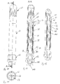
- eine Seitenansicht eines erfindungsgemäßen Düsenrohres gemäß einer zweiten bevorzugten Ausführungsform der Erfindung mit daran angeordneter Sprühdüse,
- Fig. 11
- eine Draufsicht auf das Düsenrohr der
Fig. 10 , - Fig. 12
- eine Ansicht auf die Schnittebene A-A in
Fig. 10 , - Fig. 13
- eine perspektivische Ansicht des gemäß
Fig. 12 geschnittenen Düsenrohres, - Fig. 14
- eine Seitenansicht des Düsenrohres der
Fig. 10 ohne Sprühdüse, - Fig. 15
- eine Draufsicht auf das Düsenrohr der
Fig. 14 , - Fig. 16
- eine Ansicht auf die Schnittebene A-A des Düsenrohres der
Fig. 14 , wobei ein Rückschlagventil geschlossen ist, - Fig. 17
- eine Ansicht auf die Schnittebene A-A in
Fig. 14 , wobei das Rückschlagventil geöffnet ist, - Fig. 18
- eine Ansicht auf die Schnittebene B-B in
Fig. 16 , - Fig. 19
- eine Ansicht auf die Schnittebene C-C in
Fig. 16 , - Fig. 20
- eine im Wesentlichen der
Fig. 16 entsprechende Darstellung des Düsenrohres, wobei zur Verdeutlichung ein radialer Abstand zwischen dem Absperrkörper und dem Düsenrohr bzw. dem Leitrohr und dem Düsenrohr übertrieb groß dargestellt ist, - Fig. 21
- die Einzelheit X aus
Fig. 20 , - Fig. 22
- die Einzelheit Y aus
Fig. 20 und - Fig. 23
- eine der Einzelheit Y entsprechende Ansicht einer weiteren erfindungsgemäßen Ausführungsform.
- Fig. 1
- a side view of a nozzle tube according to the invention according to a preferred embodiment of the invention arranged thereon with a spray nozzle,
- Fig. 2
- a view on the cutting plane AA the
Fig. 2 . - Fig. 3
- an isometric view of according to
Fig. 2 cut nozzle tube, - Fig. 4
- a view of the nozzle tube of
Fig. 1 without spray nozzle from behind, - Fig. 5
- a side view of the nozzle tube of
Fig. 4 . - Fig. 6
- a view of the cutting plane AA
Fig. 5 . - Fig. 7
- an isometric view of according to
Fig. 6 cut nozzle tube, - Fig. 8
- a view on the cutting plane BB in
Fig. 6 . - Fig. 9
- a view on the cutting plane CC in
Fig. 6 . - Fig. 10
- a side view of a nozzle tube according to the invention according to a second preferred embodiment of the invention with arranged thereon spray nozzle,
- Fig. 11
- a plan view of the nozzle tube of
Fig. 10 . - Fig. 12
- a view on the cutting plane AA in
Fig. 10 . - Fig. 13
- a perspective view of according to
Fig. 12 cut nozzle tube, - Fig. 14
- a side view of the nozzle tube of
Fig. 10 without spray nozzle, - Fig. 15
- a plan view of the nozzle tube of
Fig. 14 . - Fig. 16
- a view of the sectional plane AA of the nozzle tube of the
Fig. 14 with a check valve closed, - Fig. 17
- a view on the cutting plane AA in
Fig. 14 with the check valve open, - Fig. 18
- a view on the cutting plane BB in
Fig. 16 . - Fig. 19
- a view on the cutting plane CC in
Fig. 16 . - Fig. 20
- a substantially the
Fig. 16 corresponding representation of the nozzle tube, wherein for clarity a radial distance between the shut-off body and the nozzle tube or the guide tube and the nozzle tube exaggerated large, - Fig. 21
- the detail X out
Fig. 20 . - Fig. 22
- the detail Y out
Fig. 20 and - Fig. 23
- one of the detail Y corresponding view of another embodiment of the invention.
In der Darstellung der
An dem, der Sprühdüse 14 gegenüberliegenden Ende ist das Düsenrohr 10 mit einem Filterbauteil 16 versehen. Das Filterbauteil 16 weist mehrere sich in Längsrichtung des Düsenrohres 10 erstreckende Eintrittsschlitze 18 auf und ist mit einer Filterkappe 20 versehen, die ebenfalls Eintrittsschlitze für Fluid aufweist.At the end opposite the
Im Betrieb wird das Düsenrohr 10 in einen Anschweißnippel eines Spritzbalkens für zu versprühendes Fluid eingeführt, so dass wenigstens das Filterbauteil 16 innerhalb des Spritzbalkens angeordnet ist und die Sprühdüse 14 außerhalb des Spritzbalkens liegt. Zu versprühendes Fluid kann dann durch das Filterbauteil 16 in das Düsenrohr 10 eintreten und wird mittels der Sprühdüse 14 versprüht. Das Düsenrohr 10 ist für Entzunderungsdüsen vorgesehen, bei denen Fluid, beispielsweise Wasser, mit sehr hohen Drücken von mehreren 100 bar innerhalb einer Walzstraße auf eine heiße Metalloberfläche, beispielsweise Stahl oder Kupfer, gesprüht wird, um eine Zunderschicht auf der Metalloberfläche zu entfernen.In operation, the
Um zu verhindern, dass nach dem Absenken eines Fluiddrucks wesentliche Mengen von Fluid noch aus der Sprühdüse 14 austreten, ist das Düsenrohr 10 mit einem Rückschlagventil 22 versehen, wie es in der Ansicht der Schnittebene A-A in
Die Darstellung der
Steigt der Fluiddruck am Ventilsitz 26 so weit an, dass die Vorspannkraft des Wellrohres 32 überwunden wird, wird der ringförmige Absperrkörper 30 in der Darstellung der
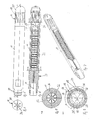
Anhand der Darstellung der
Stromabwärts des Wellrohres 32 ist ein Strahlrichter 34 angeordnet. Der Strahlrichter 34 ist einstückig mit dem Düsenrohr 10 ausgebildet und weist mehrere, sich radial nach innen erstreckende Strömungsleitflächen auf. Die Strömungsleitflächen laufen auf eine Mittellängsachse 36 des Düsenrohres 10 zu und sind parallel zu dieser Mittellängsachse 36 angeordnet. Der unmittelbar die Mittellängsachse 36 umgebende Bereich ist aber frei von Einbauten. Der Strahlrichter 34 wird aus diesem Grund auch als seelenloser Strahlrichter bezeichnet. Stromabwärts des Strahlrichters 34 schließt sich ein Fluidkanal 38 mit konstantem Querschnitt an. Dieser Fluidkanal 38 geht dann in ein Düsenmundstück 40 über, das den freien Querschnitt verjüngt und das eine Austrittsöffnung 42 aufweist. Das Düsenmundstück 40 wird mittels der Überwurfmutter 12 am Düsenrohr 10 gehalten.Downstream of the
Das Düsenrohr 10, das Filterbauteil 16 und der Strahlrichter 34 sind mittels eines Sinterverfahrens hergestellt. Dabei wird Metallpulver mit einem Kunststoffbinder vermischt und mittels Spritzguss in eine gewünschte Form gebracht. Nach dem Entfernen des Kunststoffbinders wird das Bauteil gesintert, so dass sich ein Metall-Sinterbauteil ergibt.The
Dieses Herstellungsverfahren ermöglicht es, den Strahlrichter 34 mit dem Düsenrohr 10 zusammenzusintern und auch die Ventilsitzscheibe 24 mit dem Filterbauteil 16 zusammenzusintern. Die Filterkappe 20 kann als separates Bauteil hergestellt werden, wird dann aber ebenfalls mit dem übrigen Bestandteil des Filterbauteils 16 zusammengesintert.This manufacturing method makes it possible to sinter the
Das Düsenmundstück 40 kann aus Hartmetall bestehen und ebenfalls als Sinterbauteil hergestellt werden und wird auch als Hartmetalleinsatz bezeichnet.The
Die Darstellung der
Die Darstellung der
Die Darstellung der
Anhand der Darstellung der
Die Darstellung der
Die Darstellung der
Die Darstellung der
Ebenfalls zu erkennen ist die Ventilsitzscheibe 26 sowie speziell drei Durchlasskanäle 28 in der Ventilsitzscheibe. Die drei Durchlasskanäle 28 sind jeweils in Form eines sich bogenförmig erstreckenden Langloches ausgebildet. Eine Mittellinie der bogenförmigen Langlöcher 28 liegt auf einem Kreis, der die Mittellängsachse 36 des Düsenrohres konzentrisch umgibt. Eine radial außen liegende Wandung der bogenförmigen Langlöcher 28 fällt mit einer Innenwandung des Filterbauteils 16 zusammen. Nach innen, auf die Mittellängsachse 36 zu, erstrecken sich die bogenförmigen Langlöcher bis an den Ventilsitz 24, wie in der Schnittansicht der
Die Enden der bogenförmigen Langlöcher 28 sind jeweils halbkreisförmig gestaltet, wobei die Mittelpunkte dieser Halbkreise um einen Winkel von 65° voneinander beabstandet sind. Die Mittelpunkte der halbkreisförmigen Enden zweier aneinander angrenzender Langlöcher 28 sind um 55° voneinander beabstandet.The ends of the
Mittels der drei bogenförmigen Langlöcher 28 lässt sich ein großer freier Strömungsquerschnitt und ein geringer Strömungswiderstand durch die Ventilsitzscheibe 24 hindurch erzielen, wobei gleichzeitig die verbleibenden Stege 56 zwischen den bogenförmigen Langlöchern 28 stabil genug sind, um auch sehr hohen Fluiddrücken von mehreren hundert bar standzuhalten.By means of the three
In der Darstellung der
Die Sprühdüse 62 ist auf das stromabwärts gelegene Ende des Düsenrohres 60 aufgeschraubt.The
In der Draufsicht der
In der Schnittansicht der
Das Wellrohr 76 ist an seinem, dem Absperrkörper 74 gegenüberliegenden Ende in einem Bereich 82 mit dem Düsenrohr 60 verschweißt. Das Leitrohr 78 hingegen ist mit seinem, dem Absperrkörper 74 gegenüberliegenden Ende in einem Bereich 84 verschiebbar im Düsenrohr 60 aufgenommen. Das Leitrohr 78 liegt hierzu mit seiner Außenwandung im Bereich 84 an einer Innenwandung des Düsenrohres 60 an, wobei eine Passung zwischen Leitrohr 78 und Düsenrohr 60 so gewählt ist, dass das Leitrohr 78 parallel zur Mittellängsachse 80 verschoben werden kann.The
Das Wellrohr 76 ist in der in
Stromabwärts des Stromlinienkörpers 70 ist in das Leitrohr 78 ein Strahlrichter 88 eingesetzt. Der Strahlrichter 88 weist einen die Mittellängsachse 80 konzentrisch umgebenden rohrförmigen Bereich auf, so dass also Fluid in dem die Mittellängsachse unmittelbar konzentrisch umgebenden Bereich strömen kann. Dieser rohrförmige Abschnitt wird durch insgesamt vier sich in radialer Richtung erstreckende Strömungsleitflächen, die sich bis zu einer Innenseite des Leitrohres 78 erstrecken, gehalten. Die Außenkanten der Leitflächen, die auf der Innenseite des Leitrohres 78 anliegen, sind mit dem Leitrohr beispielsweise verschweißt.Downstream of the
Die Sprühdüse 62 ist im Wesentlichen identisch zu der bereits anhand der
Die Darstellung der
An den Bereich 94, in dem der Stromlinienkörper 70 mit der Ventilsitzscheibe 68 verbunden ist, schließt sich der kegelförmig verjüngende Bereich des Ventilsitzes 72 an. Der sich kegelförmig erweiternde Bereich 92 weist am Übergang zum Bereich 94 somit einen größeren Radius auf als der Innenradius des Absperrkörpers 74. Anschließend an den sich kegelförmig verjüngenden Ventilsitz 72 schließt sich ein in Strömungsrichtung gesehen erweiternder Bereich 96 an. Ein Übergang zwischen dem sich in Strömungsrichtung gesehen verjüngenden Ventilsitz 72 und dem sich erweiternden Bereich 96 ist ausgerundet. Der sich erweiternde Bereich 96 geht dann wieder in einen sich kegelförmig verjüngenden Bereich 98 über, der dann an einer Endspitze 100 endet, die auf der Mittellängsachse 80 liegt. Durch diese Formgebung des Stromlinienkörpers 70 läßt sich überraschenderweise ein geringer Strömungswiderstand durch das Rückschlagventil erzielen und ein gutes und zeitlich gesehen konstantes Sprühbild der Düse 72 wird erzielt. Überraschend ist dabei die sich positiv auf den Strömungswiderstand und das Sprühbild auswirkende Formgebung des Stromlinienkörpers 70 stromabwärts des Ventilsitzes 72, mit dem sich zunächst wieder erweiternden Bereich 96 und dem sich dann sanft verjüngenden Bereich 98, der an der Endspitze 100 endet. Der sich verjüngende Bereich 98 nimmt dabei fast die Hälfte der Länge des gesamten Stromlinienkörpers 70 ein. Der sich kegelförmig ausgehend von der Spitze 90 erweiternde Bereich 92 nimmt dahingegen lediglich etwa ein Fünftel der Länge des Gesamtstromlinienkörpers 70 ein.At the
Die Darstellung der
Anstelle von kreiszylindrischen Durchgangsbohrungen 102 können die Durchgangsbohrungen auch in Form gekrümmter Langlöcher ausgebildet sein, beispielsweise könnte eine Speiche zwischen jeweils zwei Durchgangsbohrungen 102 ebenfalls durchgebohrt sein, um einen freien Strömungsquerschnitt noch weiter zu erhöhen. Solche Durchgangsbohrungen in Form gekrümmter Langlöcher wurden bereits anhand der
Nach Passieren der Durchgangsbohrungen 102 in der Ventilsitzscheibe 68 tritt das Fluid zwischen dem Ventilsitz 72 und dem ringförmigen Absperrkörper 74 hindurch. Wie anhand der
Nachdem das Fluid die Endspitze 100 des Stromlinienkörpers 70 passiert hat, kann es den vollständigen Innenraum des Leitrohres 78 einnehmen, bis es auf den Strahlrichter 88 auftrifft. Die Form des Strahlrichter 88 ist gut in der Schnittansicht der
Nach Passieren des Strahlrichters 88 schließt sich ein Strömungskanalabschnitt mit konstantem Querschnitt an, der durch den Innendurchmesser des Leitrohres 78 definiert ist. Dieser Strömungskanal mit konstantem Querschnitt erstreckt sich bis zu einer kegelartigen Verjüngung im Düsenmundstück 108, siehe
Das Wellrohr 76 ist im Betrieb des Düsenrohres 60 sowohl im geschlossenen Zustand der
Auf seiner radial innen liegenden Seite wird das Wellrohr 76 ebenfalls durch unter Druck stehende Flüssigkeit beaufschlagt. Unter Druck stehendes Fluid kann zwischen dem Leitrohr 78 und dem Bereich 84, siehe
Die Darstellung der
Die Darstellung der
Die Darstellung der
Wie in
Gemäß
In der Darstellung der
Claims (15)
Applications Claiming Priority (1)
| Application Number | Priority Date | Filing Date | Title |
|---|---|---|---|
| DE102011076443A DE102011076443B4 (en) | 2011-05-25 | 2011-05-25 | Check valve for spray nozzle and nozzle tube |
Publications (3)
| Publication Number | Publication Date |
|---|---|
| EP2527699A2 true EP2527699A2 (en) | 2012-11-28 |
| EP2527699A3 EP2527699A3 (en) | 2013-02-20 |
| EP2527699B1 EP2527699B1 (en) | 2015-08-05 |
Family
ID=46317149
Family Applications (1)
| Application Number | Title | Priority Date | Filing Date |
|---|---|---|---|
| EP12167835.3A Not-in-force EP2527699B1 (en) | 2011-05-25 | 2012-05-14 | Check valve for spray nozzle and nozzle tube |
Country Status (8)
| Country | Link |
|---|---|
| US (1) | US9377115B2 (en) |
| EP (1) | EP2527699B1 (en) |
| JP (1) | JP6026778B2 (en) |
| KR (1) | KR101941022B1 (en) |
| CN (1) | CN102900871B (en) |
| DE (1) | DE102011076443B4 (en) |
| ES (1) | ES2550063T3 (en) |
| RU (1) | RU2593449C2 (en) |
Families Citing this family (13)
| Publication number | Priority date | Publication date | Assignee | Title |
|---|---|---|---|---|
| FI125547B (en) * | 2014-02-19 | 2015-11-30 | Heikki Antero Pohjola | Method and apparatus for maintaining the system fluid flow pressure at a predetermined, almost constant level |
| DE102015214123B3 (en) * | 2015-07-27 | 2016-07-14 | Lechler Gmbh | Filter for high-pressure nozzle, high-pressure nozzle and method for producing a filter for a high-pressure nozzle |
| US9572555B1 (en) * | 2015-09-24 | 2017-02-21 | Ethicon, Inc. | Spray or drip tips having multiple outlet channels |
| GB201517760D0 (en) * | 2015-10-07 | 2015-11-18 | Rigdeluge Global Ltd | Nozzle apparatus |
| DE102016213551A1 (en) | 2016-07-25 | 2018-01-25 | Awg Fittings Gmbh | Nozzle for water, in particular for a water cannon |
| DE102016221729A1 (en) * | 2016-11-07 | 2018-05-09 | Lechler Gmbh | Filter jet straightener unit and high pressure nozzle unit |
| DE102018122252B4 (en) | 2018-09-12 | 2024-09-05 | Airbus Defence and Space GmbH | Check valve device and manufacture thereof |
| EP3877095A2 (en) * | 2018-11-09 | 2021-09-15 | Illinois Tool Works Inc. | Modular fluid application device for varying fluid coat weight |
| KR102306387B1 (en) * | 2019-07-02 | 2021-09-30 | 임태영 | Air Cleaning and Mist Spray System for Outdoor Applications |
| JP2021178319A (en) * | 2020-05-15 | 2021-11-18 | スプレイング システムズ カンパニー | Improved descaling nozzle assembly |
| DE102021126758A1 (en) * | 2021-10-15 | 2023-04-20 | M E S T O Spritzenfabrik Ernst Stockburger GmbH | Spray device for generating a spray jet with improved performance characteristics |
| CN114653540B (en) * | 2022-04-19 | 2023-12-22 | 深圳市启扬智能装备有限公司 | Articulated injection valve |
| CN115193602B (en) * | 2022-06-29 | 2023-08-29 | 中航工程集成设备有限公司 | Multifunctional non-return spray head |
Family Cites Families (30)
| Publication number | Priority date | Publication date | Assignee | Title |
|---|---|---|---|---|
| US2899975A (en) | 1959-08-18 | Fluid pressure regulating valve | ||
| GB344636A (en) * | 1930-02-18 | 1931-03-12 | S I A M Ltd | Improvements in non-drip valves and the like |
| US2553919A (en) | 1946-10-21 | 1951-05-22 | Burckhardt Engineering Works | Valve arrangement for filling and emptying gas tanks |
| US3258205A (en) * | 1964-08-03 | 1966-06-28 | Rain Jet Corp | Lawn sprinkler with filter of plastic foam |
| US3556128A (en) * | 1969-04-30 | 1971-01-19 | Paul J Scaglione | Pressure balanced regulating valve with flared compression disc |
| US3637187A (en) * | 1969-05-05 | 1972-01-25 | Daniel Stephen Delany | Valve with axially spaced guides and bellows operator |
| GB1460576A (en) * | 1973-09-18 | 1977-01-06 | British Petroleum Co | Flare stack burner tip |
| CH573563A5 (en) * | 1973-11-22 | 1976-03-15 | Balzers Patent Beteilig Ag | |
| US4040445A (en) * | 1974-04-08 | 1977-08-09 | Murray A. Ruben | Electrical linear force motor for servo controls, fluid valves, and the like |
| US4620597A (en) * | 1984-10-04 | 1986-11-04 | Teledyne Industries, Inc. | High pressure injection valve |
| JPH0673697B2 (en) * | 1987-10-24 | 1994-09-21 | 株式会社共立合金製作所 | Nozzle for scale removal |
| CN1017181B (en) | 1990-04-27 | 1992-06-24 | 梁济权 | Bidirectional stable pressure valve |
| DE4224497A1 (en) | 1992-07-24 | 1994-01-27 | Hilti Ag | Mouthpiece for dispensing devices that are used to dispense two-component materials |
| CN2183825Y (en) | 1994-01-25 | 1994-11-30 | 林惠瑾 | Liquid nozzle |
| JPH0852386A (en) * | 1994-08-10 | 1996-02-27 | Kyoritsu Gokin Seisakusho:Kk | Fluid jetting nozzle apparatus |
| US5862996A (en) * | 1997-01-10 | 1999-01-26 | The Procter & Gamble Company | Laminar flow nozzle |
| DE19825574A1 (en) * | 1998-06-08 | 1999-12-09 | Evertz Hydrotechnik Gmbh & Co | Biased controllable flow limiting valve, in particular spray valve, and spray bar |
| DE29815321U1 (en) * | 1998-07-10 | 1998-12-03 | Schrupp GmbH, 57518 Betzdorf | Controllable 2/2-way cartridge valve |
| US6360440B1 (en) * | 2000-09-13 | 2002-03-26 | Delphi Technologies, Inc. | Method for locating injector ball valve guide |
| JP2003159549A (en) * | 2001-09-12 | 2003-06-03 | Ikeuchi:Kk | Spray nozzle |
| KR200296586Y1 (en) * | 2002-09-03 | 2002-11-29 | 권오선 | Spiral connection tube within a check valve |
| DE60223578T2 (en) * | 2002-12-19 | 2008-09-18 | Techspace Aero S.A. | Valve with integrated drive |
| JP4321129B2 (en) * | 2003-06-17 | 2009-08-26 | 澁谷工業株式会社 | Filling valve |
| DE10343825A1 (en) * | 2003-09-22 | 2005-04-21 | Evertz Hydrotechnik Gmbh & Co | Controllable flow rate limiting valve with a movable valve piston in a housing, in particular, for spray units is provided with means which damp the valve piston motion during control processes |
| RU2271873C1 (en) * | 2004-08-04 | 2006-03-20 | Общество с ограниченной ответственностью "Фирма "МКМ" | Spray gun |
| US20070235559A1 (en) * | 2006-03-21 | 2007-10-11 | Nankai Co., Ltd | Flow control valve |
| DE102007024247B3 (en) * | 2007-05-15 | 2008-11-06 | Lechler Gmbh | High pressure nozzle and method of making a high pressure nozzle |
| EP2127755A1 (en) * | 2008-05-12 | 2009-12-02 | Pnr Italia S.R.L. | Flow guide with integrated valve |
| CN101773889B (en) | 2010-02-10 | 2012-04-25 | 岳波 | Gasification nozzle |
| US9764333B2 (en) | 2010-03-10 | 2017-09-19 | Msp Corporation | Electrical ionizer for aerosol charge conditioning and measurement |
-
2011
- 2011-05-25 DE DE102011076443A patent/DE102011076443B4/en not_active Expired - Fee Related
-
2012
- 2012-05-14 ES ES12167835.3T patent/ES2550063T3/en active Active
- 2012-05-14 EP EP12167835.3A patent/EP2527699B1/en not_active Not-in-force
- 2012-05-21 RU RU2012120616/05A patent/RU2593449C2/en not_active IP Right Cessation
- 2012-05-24 US US13/479,391 patent/US9377115B2/en not_active Expired - Fee Related
- 2012-05-24 KR KR1020120055552A patent/KR101941022B1/en active IP Right Grant
- 2012-05-25 JP JP2012120023A patent/JP6026778B2/en not_active Expired - Fee Related
- 2012-05-25 CN CN201210229980.3A patent/CN102900871B/en not_active Expired - Fee Related
Non-Patent Citations (1)
| Title |
|---|
| None |
Also Published As
| Publication number | Publication date |
|---|---|
| US9377115B2 (en) | 2016-06-28 |
| US20120298780A1 (en) | 2012-11-29 |
| RU2012120616A (en) | 2013-11-27 |
| KR101941022B1 (en) | 2019-01-22 |
| CN102900871B (en) | 2017-10-24 |
| RU2593449C2 (en) | 2016-08-10 |
| ES2550063T3 (en) | 2015-11-04 |
| EP2527699B1 (en) | 2015-08-05 |
| JP2012247060A (en) | 2012-12-13 |
| DE102011076443B4 (en) | 2013-01-17 |
| EP2527699A3 (en) | 2013-02-20 |
| JP6026778B2 (en) | 2016-11-16 |
| KR20120132393A (en) | 2012-12-05 |
| DE102011076443A1 (en) | 2012-11-29 |
| CN102900871A (en) | 2013-01-30 |
Similar Documents
| Publication | Publication Date | Title |
|---|---|---|
| EP2527699B1 (en) | Check valve for spray nozzle and nozzle tube | |
| EP1992415B1 (en) | High pressure nozzle and method for producing a high pressure nozzle | |
| EP1992414B1 (en) | Spray nozzle | |
| EP3318336B1 (en) | Filter jet aligner unit and high pressure nozzle unit | |
| DE102013203339A1 (en) | Two-fluid nozzle and method for spraying a liquid-gas mixture | |
| EP1415102B1 (en) | Closure element, especially a valve cone for a continuous pressure valve | |
| EP3139074B1 (en) | Frost-proof exterior fitting and method of mounting the same | |
| EP2682652B1 (en) | Pinch valve | |
| EP1634003B1 (en) | Fast coupling unit with integrated check valve | |
| DE3906579A1 (en) | High-pressure spray nozzle | |
| DE1500036A1 (en) | Pipeline switch and process for its manufacture | |
| DE112014000267B4 (en) | Fuel injector | |
| DE10256533A1 (en) | Nozzle, in particular atomizing nozzle for oil burners | |
| DE102012018731A1 (en) | Safety shut-off device and method for its manufacture | |
| EP3124123B1 (en) | Filter for high pressure nozzle, high pressure nozzle and method for producing a filter for a high pressure nozzle | |
| DE10343868B3 (en) | Internal high pressure forming plant for high pressure forming has filling attachment connected to transporting device | |
| DE102006028774A1 (en) | Tool fastening nut insert to hollow profile in automobile industry, includes resistance welding apparatus in which one electrode forms plunger with recess surrounding insert | |
| EP1650003A1 (en) | Device for manufacturing a tubular body | |
| DE29821499U1 (en) | Device for closing a pipe end or shaped part for the purpose of forming a weld seam in the production of a welded connection with this pipe end or shaped part and arrangement using the device | |
| EP0686798B1 (en) | Plug-in connection | |
| DE19812044C1 (en) | Thread insert for pneumatic or hydraulic systems | |
| DE29504898U1 (en) | Valve nozzle | |
| DE10064976A1 (en) | Valve unit with connection adapter has casing itself in form of functional blocking valve | |
| DE3046896C2 (en) | Hydraulic control valve in slide design with non-return valve in the pressure medium supply channel | |
| DE10212846A1 (en) | Pressure reducer for connecting and defining of HP section and LP section in fluid pipe has helical form multiple flow path extension between HP and LP section between cylinder inner wall and piston or threaded pin installed inside it |
Legal Events
| Date | Code | Title | Description |
|---|---|---|---|
| PUAI | Public reference made under article 153(3) epc to a published international application that has entered the european phase |
Free format text: ORIGINAL CODE: 0009012 |
|
| AK | Designated contracting states |
Kind code of ref document: A2 Designated state(s): AL AT BE BG CH CY CZ DE DK EE ES FI FR GB GR HR HU IE IS IT LI LT LU LV MC MK MT NL NO PL PT RO RS SE SI SK SM TR |
|
| AX | Request for extension of the european patent |
Extension state: BA ME |
|
| PUAL | Search report despatched |
Free format text: ORIGINAL CODE: 0009013 |
|
| AK | Designated contracting states |
Kind code of ref document: A3 Designated state(s): AL AT BE BG CH CY CZ DE DK EE ES FI FR GB GR HR HU IE IS IT LI LT LU LV MC MK MT NL NO PL PT RO RS SE SI SK SM TR |
|
| AX | Request for extension of the european patent |
Extension state: BA ME |
|
| RIC1 | Information provided on ipc code assigned before grant |
Ipc: F16K 15/08 20060101AFI20130117BHEP Ipc: F16K 17/04 20060101ALI20130117BHEP Ipc: F16K 15/12 20060101ALI20130117BHEP |
|
| 17P | Request for examination filed |
Effective date: 20130712 |
|
| RBV | Designated contracting states (corrected) |
Designated state(s): AL AT BE BG CH CY CZ DE DK EE ES FI FR GB GR HR HU IE IS IT LI LT LU LV MC MK MT NL NO PL PT RO RS SE SI SK SM TR |
|
| GRAP | Despatch of communication of intention to grant a patent |
Free format text: ORIGINAL CODE: EPIDOSNIGR1 |
|
| INTG | Intention to grant announced |
Effective date: 20150421 |
|
| GRAS | Grant fee paid |
Free format text: ORIGINAL CODE: EPIDOSNIGR3 |
|
| GRAA | (expected) grant |
Free format text: ORIGINAL CODE: 0009210 |
|
| AK | Designated contracting states |
Kind code of ref document: B1 Designated state(s): AL AT BE BG CH CY CZ DE DK EE ES FI FR GB GR HR HU IE IS IT LI LT LU LV MC MK MT NL NO PL PT RO RS SE SI SK SM TR |
|
| REG | Reference to a national code |
Ref country code: GB Ref legal event code: FG4D Free format text: NOT ENGLISH |
|
| REG | Reference to a national code |
Ref country code: CH Ref legal event code: EP |
|
| REG | Reference to a national code |
Ref country code: AT Ref legal event code: REF Ref document number: 740912 Country of ref document: AT Kind code of ref document: T Effective date: 20150815 |
|
| REG | Reference to a national code |
Ref country code: IE Ref legal event code: FG4D Free format text: LANGUAGE OF EP DOCUMENT: GERMAN |
|
| REG | Reference to a national code |
Ref country code: DE Ref legal event code: R096 Ref document number: 502012004008 Country of ref document: DE |
|
| REG | Reference to a national code |
Ref country code: ES Ref legal event code: FG2A Ref document number: 2550063 Country of ref document: ES Kind code of ref document: T3 Effective date: 20151104 |
|
| REG | Reference to a national code |
Ref country code: LT Ref legal event code: MG4D |
|
| REG | Reference to a national code |
Ref country code: NL Ref legal event code: MP Effective date: 20150805 |
|
| PG25 | Lapsed in a contracting state [announced via postgrant information from national office to epo] |
Ref country code: NO Free format text: LAPSE BECAUSE OF FAILURE TO SUBMIT A TRANSLATION OF THE DESCRIPTION OR TO PAY THE FEE WITHIN THE PRESCRIBED TIME-LIMIT Effective date: 20151105 Ref country code: FI Free format text: LAPSE BECAUSE OF FAILURE TO SUBMIT A TRANSLATION OF THE DESCRIPTION OR TO PAY THE FEE WITHIN THE PRESCRIBED TIME-LIMIT Effective date: 20150805 Ref country code: LV Free format text: LAPSE BECAUSE OF FAILURE TO SUBMIT A TRANSLATION OF THE DESCRIPTION OR TO PAY THE FEE WITHIN THE PRESCRIBED TIME-LIMIT Effective date: 20150805 Ref country code: GR Free format text: LAPSE BECAUSE OF FAILURE TO SUBMIT A TRANSLATION OF THE DESCRIPTION OR TO PAY THE FEE WITHIN THE PRESCRIBED TIME-LIMIT Effective date: 20151106 Ref country code: LT Free format text: LAPSE BECAUSE OF FAILURE TO SUBMIT A TRANSLATION OF THE DESCRIPTION OR TO PAY THE FEE WITHIN THE PRESCRIBED TIME-LIMIT Effective date: 20150805 |
|
| PG25 | Lapsed in a contracting state [announced via postgrant information from national office to epo] |
Ref country code: SE Free format text: LAPSE BECAUSE OF FAILURE TO SUBMIT A TRANSLATION OF THE DESCRIPTION OR TO PAY THE FEE WITHIN THE PRESCRIBED TIME-LIMIT Effective date: 20150805 Ref country code: IS Free format text: LAPSE BECAUSE OF FAILURE TO SUBMIT A TRANSLATION OF THE DESCRIPTION OR TO PAY THE FEE WITHIN THE PRESCRIBED TIME-LIMIT Effective date: 20151205 Ref country code: HR Free format text: LAPSE BECAUSE OF FAILURE TO SUBMIT A TRANSLATION OF THE DESCRIPTION OR TO PAY THE FEE WITHIN THE PRESCRIBED TIME-LIMIT Effective date: 20150805 Ref country code: PT Free format text: LAPSE BECAUSE OF FAILURE TO SUBMIT A TRANSLATION OF THE DESCRIPTION OR TO PAY THE FEE WITHIN THE PRESCRIBED TIME-LIMIT Effective date: 20151207 Ref country code: RS Free format text: LAPSE BECAUSE OF FAILURE TO SUBMIT A TRANSLATION OF THE DESCRIPTION OR TO PAY THE FEE WITHIN THE PRESCRIBED TIME-LIMIT Effective date: 20150805 Ref country code: PL Free format text: LAPSE BECAUSE OF FAILURE TO SUBMIT A TRANSLATION OF THE DESCRIPTION OR TO PAY THE FEE WITHIN THE PRESCRIBED TIME-LIMIT Effective date: 20150805 |
|
| PG25 | Lapsed in a contracting state [announced via postgrant information from national office to epo] |
Ref country code: NL Free format text: LAPSE BECAUSE OF FAILURE TO SUBMIT A TRANSLATION OF THE DESCRIPTION OR TO PAY THE FEE WITHIN THE PRESCRIBED TIME-LIMIT Effective date: 20150805 |
|
| PG25 | Lapsed in a contracting state [announced via postgrant information from national office to epo] |
Ref country code: DK Free format text: LAPSE BECAUSE OF FAILURE TO SUBMIT A TRANSLATION OF THE DESCRIPTION OR TO PAY THE FEE WITHIN THE PRESCRIBED TIME-LIMIT Effective date: 20150805 Ref country code: EE Free format text: LAPSE BECAUSE OF FAILURE TO SUBMIT A TRANSLATION OF THE DESCRIPTION OR TO PAY THE FEE WITHIN THE PRESCRIBED TIME-LIMIT Effective date: 20150805 Ref country code: SK Free format text: LAPSE BECAUSE OF FAILURE TO SUBMIT A TRANSLATION OF THE DESCRIPTION OR TO PAY THE FEE WITHIN THE PRESCRIBED TIME-LIMIT Effective date: 20150805 Ref country code: CZ Free format text: LAPSE BECAUSE OF FAILURE TO SUBMIT A TRANSLATION OF THE DESCRIPTION OR TO PAY THE FEE WITHIN THE PRESCRIBED TIME-LIMIT Effective date: 20150805 |
|
| REG | Reference to a national code |
Ref country code: DE Ref legal event code: R097 Ref document number: 502012004008 Country of ref document: DE |
|
| REG | Reference to a national code |
Ref country code: FR Ref legal event code: PLFP Year of fee payment: 5 |
|
| PG25 | Lapsed in a contracting state [announced via postgrant information from national office to epo] |
Ref country code: RO Free format text: LAPSE BECAUSE OF FAILURE TO SUBMIT A TRANSLATION OF THE DESCRIPTION OR TO PAY THE FEE WITHIN THE PRESCRIBED TIME-LIMIT Effective date: 20150805 |
|
| PLBE | No opposition filed within time limit |
Free format text: ORIGINAL CODE: 0009261 |
|
| STAA | Information on the status of an ep patent application or granted ep patent |
Free format text: STATUS: NO OPPOSITION FILED WITHIN TIME LIMIT |
|
| 26N | No opposition filed |
Effective date: 20160509 |
|
| PG25 | Lapsed in a contracting state [announced via postgrant information from national office to epo] |
Ref country code: SI Free format text: LAPSE BECAUSE OF FAILURE TO SUBMIT A TRANSLATION OF THE DESCRIPTION OR TO PAY THE FEE WITHIN THE PRESCRIBED TIME-LIMIT Effective date: 20150805 |
|
| PG25 | Lapsed in a contracting state [announced via postgrant information from national office to epo] |
Ref country code: LU Free format text: LAPSE BECAUSE OF FAILURE TO SUBMIT A TRANSLATION OF THE DESCRIPTION OR TO PAY THE FEE WITHIN THE PRESCRIBED TIME-LIMIT Effective date: 20160514 |
|
| REG | Reference to a national code |
Ref country code: CH Ref legal event code: PL |
|
| PG25 | Lapsed in a contracting state [announced via postgrant information from national office to epo] |
Ref country code: LI Free format text: LAPSE BECAUSE OF NON-PAYMENT OF DUE FEES Effective date: 20160531 Ref country code: CH Free format text: LAPSE BECAUSE OF NON-PAYMENT OF DUE FEES Effective date: 20160531 |
|
| REG | Reference to a national code |
Ref country code: IE Ref legal event code: MM4A |
|
| REG | Reference to a national code |
Ref country code: FR Ref legal event code: PLFP Year of fee payment: 6 |
|
| PG25 | Lapsed in a contracting state [announced via postgrant information from national office to epo] |
Ref country code: IE Free format text: LAPSE BECAUSE OF NON-PAYMENT OF DUE FEES Effective date: 20160514 |
|
| REG | Reference to a national code |
Ref country code: FR Ref legal event code: PLFP Year of fee payment: 7 |
|
| PG25 | Lapsed in a contracting state [announced via postgrant information from national office to epo] |
Ref country code: CY Free format text: LAPSE BECAUSE OF FAILURE TO SUBMIT A TRANSLATION OF THE DESCRIPTION OR TO PAY THE FEE WITHIN THE PRESCRIBED TIME-LIMIT Effective date: 20150805 Ref country code: HU Free format text: LAPSE BECAUSE OF FAILURE TO SUBMIT A TRANSLATION OF THE DESCRIPTION OR TO PAY THE FEE WITHIN THE PRESCRIBED TIME-LIMIT; INVALID AB INITIO Effective date: 20120514 Ref country code: SM Free format text: LAPSE BECAUSE OF FAILURE TO SUBMIT A TRANSLATION OF THE DESCRIPTION OR TO PAY THE FEE WITHIN THE PRESCRIBED TIME-LIMIT Effective date: 20150805 |
|
| PG25 | Lapsed in a contracting state [announced via postgrant information from national office to epo] |
Ref country code: TR Free format text: LAPSE BECAUSE OF FAILURE TO SUBMIT A TRANSLATION OF THE DESCRIPTION OR TO PAY THE FEE WITHIN THE PRESCRIBED TIME-LIMIT Effective date: 20150805 Ref country code: MC Free format text: LAPSE BECAUSE OF FAILURE TO SUBMIT A TRANSLATION OF THE DESCRIPTION OR TO PAY THE FEE WITHIN THE PRESCRIBED TIME-LIMIT Effective date: 20150805 Ref country code: MT Free format text: LAPSE BECAUSE OF FAILURE TO SUBMIT A TRANSLATION OF THE DESCRIPTION OR TO PAY THE FEE WITHIN THE PRESCRIBED TIME-LIMIT Effective date: 20150805 Ref country code: MK Free format text: LAPSE BECAUSE OF FAILURE TO SUBMIT A TRANSLATION OF THE DESCRIPTION OR TO PAY THE FEE WITHIN THE PRESCRIBED TIME-LIMIT Effective date: 20150805 |
|
| PG25 | Lapsed in a contracting state [announced via postgrant information from national office to epo] |
Ref country code: BG Free format text: LAPSE BECAUSE OF FAILURE TO SUBMIT A TRANSLATION OF THE DESCRIPTION OR TO PAY THE FEE WITHIN THE PRESCRIBED TIME-LIMIT Effective date: 20150805 |
|
| PG25 | Lapsed in a contracting state [announced via postgrant information from national office to epo] |
Ref country code: AL Free format text: LAPSE BECAUSE OF FAILURE TO SUBMIT A TRANSLATION OF THE DESCRIPTION OR TO PAY THE FEE WITHIN THE PRESCRIBED TIME-LIMIT Effective date: 20150805 |
|
| PGFP | Annual fee paid to national office [announced via postgrant information from national office to epo] |
Ref country code: DE Payment date: 20190523 Year of fee payment: 8 Ref country code: ES Payment date: 20190619 Year of fee payment: 8 Ref country code: IT Payment date: 20190521 Year of fee payment: 8 |
|
| PGFP | Annual fee paid to national office [announced via postgrant information from national office to epo] |
Ref country code: BE Payment date: 20190521 Year of fee payment: 8 Ref country code: FR Payment date: 20190521 Year of fee payment: 8 |
|
| PGFP | Annual fee paid to national office [announced via postgrant information from national office to epo] |
Ref country code: GB Payment date: 20190523 Year of fee payment: 8 Ref country code: AT Payment date: 20190517 Year of fee payment: 8 |
|
| REG | Reference to a national code |
Ref country code: DE Ref legal event code: R119 Ref document number: 502012004008 Country of ref document: DE |
|
| REG | Reference to a national code |
Ref country code: AT Ref legal event code: MM01 Ref document number: 740912 Country of ref document: AT Kind code of ref document: T Effective date: 20200514 |
|
| PG25 | Lapsed in a contracting state [announced via postgrant information from national office to epo] |
Ref country code: AT Free format text: LAPSE BECAUSE OF NON-PAYMENT OF DUE FEES Effective date: 20200514 |
|
| REG | Reference to a national code |
Ref country code: BE Ref legal event code: MM Effective date: 20200531 |
|
| GBPC | Gb: european patent ceased through non-payment of renewal fee |
Effective date: 20200514 |
|
| PG25 | Lapsed in a contracting state [announced via postgrant information from national office to epo] |
Ref country code: FR Free format text: LAPSE BECAUSE OF NON-PAYMENT OF DUE FEES Effective date: 20200531 Ref country code: GB Free format text: LAPSE BECAUSE OF NON-PAYMENT OF DUE FEES Effective date: 20200514 |
|
| PG25 | Lapsed in a contracting state [announced via postgrant information from national office to epo] |
Ref country code: BE Free format text: LAPSE BECAUSE OF NON-PAYMENT OF DUE FEES Effective date: 20200531 Ref country code: DE Free format text: LAPSE BECAUSE OF NON-PAYMENT OF DUE FEES Effective date: 20201201 |
|
| REG | Reference to a national code |
Ref country code: ES Ref legal event code: FD2A Effective date: 20210930 |
|
| PG25 | Lapsed in a contracting state [announced via postgrant information from national office to epo] |
Ref country code: IT Free format text: LAPSE BECAUSE OF NON-PAYMENT OF DUE FEES Effective date: 20200514 |
|
| PG25 | Lapsed in a contracting state [announced via postgrant information from national office to epo] |
Ref country code: ES Free format text: LAPSE BECAUSE OF NON-PAYMENT OF DUE FEES Effective date: 20200515 |