EP2527125B1 - Mold apparatus - Google Patents
Mold apparatus Download PDFInfo
- Publication number
- EP2527125B1 EP2527125B1 EP12004040.7A EP12004040A EP2527125B1 EP 2527125 B1 EP2527125 B1 EP 2527125B1 EP 12004040 A EP12004040 A EP 12004040A EP 2527125 B1 EP2527125 B1 EP 2527125B1
- Authority
- EP
- European Patent Office
- Prior art keywords
- plate
- mold
- cooling
- cavity
- cavity mold
- Prior art date
- Legal status (The legal status is an assumption and is not a legal conclusion. Google has not performed a legal analysis and makes no representation as to the accuracy of the status listed.)
- Not-in-force
Links
- 238000001816 cooling Methods 0.000 claims description 177
- 238000010438 heat treatment Methods 0.000 claims description 35
- 239000002826 coolant Substances 0.000 claims description 26
- 239000000463 material Substances 0.000 claims description 15
- 239000011247 coating layer Substances 0.000 claims description 9
- 229910000881 Cu alloy Inorganic materials 0.000 claims description 3
- 229910052790 beryllium Inorganic materials 0.000 claims description 3
- ATBAMAFKBVZNFJ-UHFFFAOYSA-N beryllium atom Chemical compound [Be] ATBAMAFKBVZNFJ-UHFFFAOYSA-N 0.000 claims description 3
- 238000002347 injection Methods 0.000 description 33
- 239000007924 injection Substances 0.000 description 33
- 238000000034 method Methods 0.000 description 28
- 238000009826 distribution Methods 0.000 description 18
- 239000011342 resin composition Substances 0.000 description 10
- 238000001746 injection moulding Methods 0.000 description 9
- 230000004308 accommodation Effects 0.000 description 8
- CXOWYMLTGOFURZ-UHFFFAOYSA-N azanylidynechromium Chemical compound [Cr]#N CXOWYMLTGOFURZ-UHFFFAOYSA-N 0.000 description 8
- 238000000465 moulding Methods 0.000 description 8
- 229920005989 resin Polymers 0.000 description 7
- 239000011347 resin Substances 0.000 description 7
- 150000001875 compounds Chemical class 0.000 description 6
- 229910000831 Steel Inorganic materials 0.000 description 5
- 238000005516 engineering process Methods 0.000 description 5
- 239000010959 steel Substances 0.000 description 5
- 230000002708 enhancing effect Effects 0.000 description 4
- 229910001220 stainless steel Inorganic materials 0.000 description 4
- 239000010935 stainless steel Substances 0.000 description 4
- 238000004381 surface treatment Methods 0.000 description 4
- 239000000853 adhesive Substances 0.000 description 3
- 230000001070 adhesive effect Effects 0.000 description 3
- 239000011248 coating agent Substances 0.000 description 3
- 238000000576 coating method Methods 0.000 description 3
- 230000003247 decreasing effect Effects 0.000 description 3
- 230000001965 increasing effect Effects 0.000 description 3
- 238000004519 manufacturing process Methods 0.000 description 3
- 238000005192 partition Methods 0.000 description 3
- 238000005496 tempering Methods 0.000 description 3
- ATJFFYVFTNAWJD-UHFFFAOYSA-N Tin Chemical compound [Sn] ATJFFYVFTNAWJD-UHFFFAOYSA-N 0.000 description 2
- 230000015572 biosynthetic process Effects 0.000 description 2
- 230000003111 delayed effect Effects 0.000 description 2
- 230000000694 effects Effects 0.000 description 2
- 238000005259 measurement Methods 0.000 description 2
- 238000010422 painting Methods 0.000 description 2
- RYGMFSIKBFXOCR-UHFFFAOYSA-N Copper Chemical compound [Cu] RYGMFSIKBFXOCR-UHFFFAOYSA-N 0.000 description 1
- BQCADISMDOOEFD-UHFFFAOYSA-N Silver Chemical compound [Ag] BQCADISMDOOEFD-UHFFFAOYSA-N 0.000 description 1
- 229910001315 Tool steel Inorganic materials 0.000 description 1
- 238000005299 abrasion Methods 0.000 description 1
- 230000001133 acceleration Effects 0.000 description 1
- 238000005229 chemical vapour deposition Methods 0.000 description 1
- 239000011651 chromium Substances 0.000 description 1
- 229910052802 copper Inorganic materials 0.000 description 1
- 239000010949 copper Substances 0.000 description 1
- 230000001419 dependent effect Effects 0.000 description 1
- 238000010894 electron beam technology Methods 0.000 description 1
- 230000007613 environmental effect Effects 0.000 description 1
- 239000007789 gas Substances 0.000 description 1
- 239000011810 insulating material Substances 0.000 description 1
- 239000010410 layer Substances 0.000 description 1
- 239000007769 metal material Substances 0.000 description 1
- 239000012778 molding material Substances 0.000 description 1
- 230000003287 optical effect Effects 0.000 description 1
- 238000000059 patterning Methods 0.000 description 1
- 230000000704 physical effect Effects 0.000 description 1
- 238000007747 plating Methods 0.000 description 1
- 230000003252 repetitive effect Effects 0.000 description 1
- 229910052709 silver Inorganic materials 0.000 description 1
- 239000004332 silver Substances 0.000 description 1
- 239000000126 substance Substances 0.000 description 1
- 239000000758 substrate Substances 0.000 description 1
- 230000003075 superhydrophobic effect Effects 0.000 description 1
- 229920003002 synthetic resin Polymers 0.000 description 1
- 239000000057 synthetic resin Substances 0.000 description 1
- 239000013077 target material Substances 0.000 description 1
Images







Classifications
-
- B—PERFORMING OPERATIONS; TRANSPORTING
- B29—WORKING OF PLASTICS; WORKING OF SUBSTANCES IN A PLASTIC STATE IN GENERAL
- B29C—SHAPING OR JOINING OF PLASTICS; SHAPING OF MATERIAL IN A PLASTIC STATE, NOT OTHERWISE PROVIDED FOR; AFTER-TREATMENT OF THE SHAPED PRODUCTS, e.g. REPAIRING
- B29C45/00—Injection moulding, i.e. forcing the required volume of moulding material through a nozzle into a closed mould; Apparatus therefor
- B29C45/17—Component parts, details or accessories; Auxiliary operations
- B29C45/72—Heating or cooling
- B29C45/73—Heating or cooling of the mould
-
- B—PERFORMING OPERATIONS; TRANSPORTING
- B29—WORKING OF PLASTICS; WORKING OF SUBSTANCES IN A PLASTIC STATE IN GENERAL
- B29C—SHAPING OR JOINING OF PLASTICS; SHAPING OF MATERIAL IN A PLASTIC STATE, NOT OTHERWISE PROVIDED FOR; AFTER-TREATMENT OF THE SHAPED PRODUCTS, e.g. REPAIRING
- B29C45/00—Injection moulding, i.e. forcing the required volume of moulding material through a nozzle into a closed mould; Apparatus therefor
- B29C45/17—Component parts, details or accessories; Auxiliary operations
- B29C45/72—Heating or cooling
- B29C45/73—Heating or cooling of the mould
- B29C2045/7393—Heating or cooling of the mould alternately heating and cooling
Definitions
- the present invention relates to an injection mold apparatus for manufacturing a resin injection molded article, and more particularly, to an injection mold apparatus having a heating means and a cooling means in the mold apparatus to heat or cool a mold during the injection process.
- Injection mold is a typical method of molding a synthetic resin such as plastic or the like.
- molten resin is injected and filled into a cavity of the mold formed in a certain shape and then cooled and hardened to mold a product having the same shape as the cavity.
- a cooling plate is provided at a rear surface of the cavity mold plate having a heating means, and the cooling plate is brought into contact with the cavity mold plate during the cooling process, thereby performing rapid cooling.
- the cooling plate should be uniformly brought into contact with the cavity mold plate to enhance the cooling efficiency and reduce the cooling temperature variation, thereby improving the surface state of the injection molded article.
- the cavity mold plate is rapidly cooled down in a high-temperature state, and therefore thermal expansion and deformation occurs in a mass production system requiring frequent use. As a result, the cavity mold plate and the cooling plate are not uniformly brought into contact with each other, thereby causing a problem of severe cooling temperature variation.
- US 2009/0212464 A1 describes a molding apparatus including a cavity mold with a cavity surface for defining a cavity in which a molten injection material is injected, and a core mold with a core surface for defining the cavity upon engagement with the cavity mold.
- the core mold has an intermediate core mold plate having the core surface and a support plate.
- a guide pin inserted into a guide hole formed in the cavity mold and fitted through the intermediate core mold plate to allow the intermediate core mold plate to be moved only in a forward and backward direction is fixed to the support plate.
- a first spring is installed between the intermediate core mold plate and the support plate, a first heating means is installed to a parting surface of the intermediate core mold plate and a cooling means is installed to the support plate.
- US 2011/069361 relates to injection moldings, an injection-molding apparatus and a method thereof.
- the injection-molding apparatus comprises a cavity mold having a cavity, a core mold having a core surface to form a molding space for injection moldings when being joined to the cavity mold, a heating unit for heating the cavity mold or the core mold, a cooling unit for cooling the cavity mold or the core mold, and a patterning stamp having a micrometer or nanometer sized pattern and provided on an inner surface of the molding space.
- a micrometer or nanometer sized pattern is formed on a surface of injection moldings so as to have a super-hydrophobic characteristic and an optical characteristic, and a micrometer or nanometer sized pattern of a complex structure can be implemented.
- JP 2003 062884 A relates to an injection molding device being of such a structure that a molding material is supplied into cavities and formed by a mold member of the movable half side and the mold member of the cavity half side and the mold member of the cavity half side is equipped with a cooling circuit.
- the mold member of the cavity half side is constituted of a movable plate which forms the cavities and with the mold member of the movable half side and a fixed base which supports the movable plate in such a way that the latter is movable between a mold opening position and a mold closing position.
- the cooling circuit is formed on the fixed base.
- JP 2003 231165 A describes a resin moding die for molding a resin molded product comprising a main mold, an insert member which is assembled into the main mold and transfers the shape of a resin finished product, a heating block which can come into contact with and be set apart from the insert member, a heating means for heating the heating block and a cooling means for cooling a cooling block.
- CN 201 721 022 U relates to a still further mold.
- JP H05 177640 A describes a temperature control structure of a mold being constituted so that the gaps formed within temperature control chambers by partition walls are used as second temperature control passages when temperature control blocks having first temperature control passages are isolated from the partition walls to supply a second heating medium.
- FIG. 4 and 5 of JP H05 177640 A disclose insulating material 21 to 25, 31 to 36 provided within blocks 6 and 7, which serve to insulate the blocks 6 and 7 from the struts 16a to 16d are not adapted to conduct any heat away from a cavity mold part.
- the present invention is contrived to solve the foregoing problems in the related art, and an object of the present disclosure is to provide a mold apparatus capable of uniformly cooling a surface of the mold.
- Another object of the present disclosure is to provide a mold apparatus capable of reducing the cooling temperature variation to decrease failure rate and ensure uniform quality.
- Still another object of the present disclosure is to provide a mold apparatus capable of enhancing the cooling speed and cooling efficiency to enhance the productivity.
- a mold apparatus including a cavity mold comprising a cavity mold plate formed with a cavity at a front surface thereof and provided with a heating means at an inner portion thereof, and a cooling plate brought into contact with or separated from a rear surface of the cavity mold plate and provided with a cooling means at an inner portion thereof; and a core mold configured to determine the cavity together with the cavity mold plate, wherein the cooling plate is formed with two or more divided cooling plate parts.
- a mold apparatus including a cavity mold comprising a cavity mold plate formed with a cavity at a front surface thereof and provided with a heating means at an inner portion thereof, a base configured to support the cavity mold plate, and a cooling plate fixed between the cavity mold plate and the base to be brought into contact with or separated from the cavity mold plate and provided with a first cooling means at an inner portion thereof; a core mold provided with a core mold plate for determining the cavity together with the cavity mold plate, and including a heating means and a second cooling means disposed in the core mold plate; and a controller configured to control the operation of the heating means and cooling means, wherein the cavity mold plate includes a third cooling means.
- a cooling plate of the mold is divided and each of the divided cooling plate parts of the cooling plate is closely adhered to a rear surface of the cavity mold plate. Accordingly, a cooling temperature variation of the mold can be reduced to decrease failure rate and ensure uniform quality.
- a contact pressure is provided such that a cooling plate can be more uniformly adhered to the mold to reduce a cooling temperature variation of the mold and improve the cooling speed and efficiency, thereby enhancing the productivity.
- a cooling temperature variation of the mold can be compensated in consideration of structural features of the cavity. Accordingly, it may be possible to achieve a uniform cooling temperature distribution of the mold.
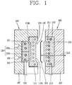
- FIG. 1 is a side cross-sectional view illustrating a mold apparatus according to a first embodiment of the present invention
- FIG. 2 is a side cross-sectional view illustrating a combined state of the mold apparatus in FIG. 1 .
- a mold apparatus includes a cavity mold 100, and a core mold 200 combined with a front surface of the cavity mold plate.
- the cavity mold 100 is a fixed mold, including a cavity mold comprising a cavity mold plate 110 formed with a cavity 120 at a front surface 110a thereof and provided with a heating means 111 at an inner portion thereof, and a cooling plate 130 brought into contact with or separated from a rear surface 110b of the cavity mold plate and provided with a cooling means 131 at an inner portion thereof.
- the cavity mold 100 may include a base 140 at which the cavity mold plate is placed, an accommodation space 150 between the cavity mold plate and the base to movably accommodate the cooling plate, and a cooling plate transfer means 160 configured to transfer the cooling plate such that the cooling plate is brought into contact with or separated from the cavity mold plate in the accommodation space.
- the cavity mold plate 110 is detachably supported and fixed to the base 140 fixed and supported by the ground or support structure (not shown) as illustrated in FIG. 1 .
- the cavity mold plate 110 is engaged with a core mold plate 210 of the core mold 200 which will be described later to form a space of the cavity 120 capable of forming an injection molded article 300, and to this end, provided with a concaved portion for forming part of the cavity 120 at a front surface 110a of the cavity mold plate 110.
- the cavity mold plate 110 may include a heating means 111 for maintaining the temperature of the mold at a high temperature to perform molding. As illustrated in FIG. 1 , the heating means 111 is embedded in a groove formed at an inner portion of the cavity mold plate, and an electric heater is typically used therefor. The heating means 111 is separated from a front surface 110a of the cavity mold plate 110 by a predetermined distance and thus unexposed on the front surface. Furthermore, a plurality of grooves in which the heating means is embedded are formed to be separated from one another along a front surface of the cavity mold plate. Accordingly, the heating means can uniformly transfer heat along the cavity in which the injection molded article is placed.
- the cooling plate 130 is provided at a rear surface 110b of the cavity mold plate, and provided to be moved within the accommodation space 150 formed between the cavity mold plate 110 and base 140.
- the cooling plate 130 can be moved to be brought into contact with a rear surface 110b of the cavity mold plate.
- the movement of the cooling plate is enabled by the cooling plate transfer means 160 provided at the base to be combined with a rear surface of the cooling plate.
- the cooling plate transfer means 160 may be configured with a hydraulic or pneumatic device.
- the cooling plate 130 includes a first cooling means 131 disposed therein.
- the first cooling means 131 is provided with a cooling passage through which coolant flows formed at an inner portion of the cooling plate.
- the coolant is supplied to the coolant passage through a coolant supply pipe 132 connected to an outside of the cavity mold.
- the coolant passage is uniformly formed along the coolant passage to uniformly provide a cooling effect of the cavity mold plate by means of the cooling plate.
- the cooling plate 130 may be formed with at least two or more divided cooling plate parts 130a, 130b.
- FIG. 3 illustrates an embodiment in which the cooling plate is divided into two surfaces
- FIG. 4 illustrates an embodiment in which the cooling plate is divided into four surfaces.
- the cooling plate in a mold apparatus according to the present invention is not limited to this, and all embodiments in which the cooling plate is divided into at least two or more surfaces are within the scope of the invention.
- the cooling plate 130 is divided into two separate surfaces 130a, 130b.
- the first cooling means 131 is provided at each divided cooling plate part, and the cooling plate transfer means 160 connected to the each divided cooling plate part is provided at a rear surface thereof.
- the cooling plate transfer means 160 is provided at the each divided cooling plate part, and connected to a central portion of the each divided cooling plate part.
- the cooling plate 130 is divided into four separate surfaces 130c, 130d, 130e, 130f. Each of the four separate surfaces is also provided with a cooling means, and the cooling plate transfer means 160 is connected to a rear surface thereof.
- FIG. 4 illustrates a rear surface of the cooling plate 130.
- the cooling plate 130 is formed with combining holes 134c, 134d, 134e, 134f, respectively, connected to the cooling plate transfer means 160 connected to each divided cooling plate part.
- the divided cooling plate parts are separated from one another. Accordingly, the operation of the cooling plate transfer means connected to each divided cooling plate part may be exhibited in a different manner. In other words, a height of the each divided cooling plate part being brought into contact with the cavity mold plate may be formed in a different manner by the cooling plate transfer means.
- the cooling plate 130 is divided in accordance with a rear surface of the cavity mold plate 110 such that each divided cooling plate part of the cooling plate is closely adhered to a rear surface of the cavity mold plate.
- the divides surfaces 130a, 130b, 130c, 130d, 130e, 130f may include a plurality of elastic bodies 133 mounted between the base 140 and the surfaces.
- FIG. 2 illustrates a position at which the elastic body is mounted, and specifically, FIG. 5 illustrates a state in which the elastic body 133 is mounted on the cooling plate 130.
- the elastic bodies 133 are formed with coil springs, respectively, and mounted at a rear surface of the cooling plate 130.
- the elastic bodies 133 are symmetrically mounted at each corner of the divided cooling plate parts, respectively, around the combining holes 134a, 134b through which the cooling plate transfer means 160 is connected to the cooling plate on the each divided cooling plate parts 130a, 130b.
- the each divided cooling plate part is closely adhered to a rear surface of the cavity mold plate by the cooling plate transfer means, and the elastic body forms a contact pressure, thereby allowing the divided cooling plate part to be more uniformly brought into contact therewith.
- the cooling plate 130 may be selectively combined with the divided cooling plate parts with different materials.
- the first divided cooling plate part 130a and second divided cooling plate part 130b can be provided with different materials on the two divided cooling plate parts.
- the divided cooling plate parts having different thermal conductivities are combined with one another to compensate the cooling temperature variation by considering that local cooling temperature variations are generated on the cavity mold plate due to a structural feature of the cavity 120. Accordingly, it may be possible to achieve more uniform cooling temperature distribution.
- the core mold 200 may be provided in a movable manner to be combined with a front surface of the cavity mold plate 100.
- a transfer means (not shown) may be connected to the base 220 of the core mold 200 so as to be moved toward the cavity mold plate 100, and a guide member (not shown) or the like may be also provided thereon.
- the core mold 200 is provided with the core mold plate 210 forming the cavity 120 in accordance with the cavity mold plate, and the core mold plate is provided with additional heating means 211 and cooling means 212 disposed therein other than the cavity mold plate 100, and provided with a coolant supply pipe 213.
- the detailed description of the heating means, cooling means, and the like, in the core mold plate 210 will be omitted when the description of the cavity mold plate is redundant.
- a mold compound injection pipe 310 passing through the mold is provided at the core mold 200.
- the injection mold compound 300 injected by the mold compound injection pipe is schematically illustrated in FIG. 1 .
- injection molding by the cavity mold 100 and core mold 200 is carried out as follows.
- the heating means 111, 211 of the cavity mold plate and core mold plate are operated in a state that the cooling plate 130 is separated from the cavity mold plate 110 as illustrated in FIG. 1 to heat the mold plates, thereby maintaining a high-temperature state.
- the cavity mold and core mold are combined with each other, and thus the cavity mold plate 110 and core mold plate 210 form the cavity 120.
- the injection mold compound 300 is injected and filled in the heated cavity 120 in a high-temperature state.
- the cooling plate transfer means 160 is operated and the cooling plate 130 is brought into contact with a rear surface of the cavity mold plate 110. Furthermore, the first cooling means 131 of the cooling plate and the second cooling means 212 of the core mold plate are operated to perform cooling.
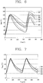
- FIGS. 6 and 7 illustrate temperature distribution at various points of the mold in a state that the divided cooling plate 130 is not provided therein and in a state that the divided cooling plate 130 is provided therein, respectively.
- the temperature distribution graph can be obtained by embedding thermocouples in various different positions of the cavity mold plate.
- temperatures are distributed in a broad range based on time at various positions of the mold in a state that the divided cooling plate 130 is not provided therein.
- temperatures based on time at various positions of the mold are distributed in a narrow range in a state that the divided cooling plate 130 is provided therein.
- the temperature at a specific position of the mold is excessively high in the state of FIG. 6 , the temperature that can be raised during the entire molding process is restrictive. However, the entire temperature distribution of the mold is narrowly formed in the state of FIG. 7 and thus the temperature of the mold can be sufficiently raised. Accordingly, since the injection is carried out in a high-temperature state, a failure rate of the injection molded articles can be reduced, thereby securing uniform quality.
- an idle time may be required to prevent the entire temperature distribution of the mold from being increased in the middle of the repetitive mass production process.
- temperature distribution is not large, and thus an unnecessary idle time can be reduced, thereby enhancing work efficiency or productivity.
- FIGS. 8 and 9 are views illustrating a mold apparatus according to a second embodiment of the present invention.
- the second embodiment will be described with reference to FIGS. 8 and 9 , and the same elements are designated with the same numeral references and their redundant description will be omitted.
- the second embodiment may further include a support member 170 a lateral surface of which is combined with the base and the other lateral surface of which is combined with a rear surface of the cavity mold plate within the accommodation space 150 of the first embodiment.
- the support member 170 supports the cavity mold plate 110 in a pillar shaped configuration, and has a substantially cylindrical shape.
- the support member 170 passes through the cooling plate 130 to be mounted within the accommodation space 150.
- a lateral surface of the support member 170 is combined with the base 140 within the accommodation space 150 and the other lateral surface thereof is combined with a rear surface 110b of the cavity mold plate.
- the cooling plate 130 is provided with a through hole 134 through which the support member passes. Accordingly, the support member passes through the through hole 134 to support the cavity mold plate 110 against the base 140. Through this, a rear surface of the cavity mold plate having a low thickness is supported by a pillar shaped support member, thereby supporting the cavity mold plate against a pressure applied through a front surface of the cavity mold plate. Accordingly, it may be possible to effectively increase structural strength even if the thickness of the cavity mold plate is not high.
- the movement of the cooling plate 130 within the accommodation space is guided by the support member.
- the cooling plate 130 is moved by the cooling plate transfer means 160 within the accommodation space 150, and the support member 170 may also perform the role of guiding the movement of the cooling plate.
- FIGS. 11 and 12 are views illustrating the support member according to modified examples.
- the support member 170 may include the coolant passage 171 formed therein.
- the coolant passage 171 may include at least one parallel passages 171a in parallel to but separated from the cavity mold plate and a connecting passage 171b for supplying and collecting coolant to and from the parallel passage. Accordingly, coolant supplied through the connecting passage flows through the parallel passage to be brought into contact with the rear surface 110b of the cavity mold plate brought into contact with the support member to exchange heat, thereby cooling the cavity mold plate.
- an insulating plate 172 may be provided at a portion brought into contact with the rear surface 110b of the cavity mold plate.
- the insulating plate 172 prevents the heat of the heated cavity mold plate in a high-temperature state from being transferred to the base 140 through the support member 170 without being heat exchanged through the cooling plate 130. Furthermore, deformation or damage due to the support member may be prevented.
- a plurality of support members 170 may be provided therein.
- a plurality of support member 170 pass through a plurality of through holes to be combined with the cooling plate 130.
- a plurality of through holes 133 corresponding to the number of support members are provided therein.
- the support member may be formed of a stainless steel (STS) material. Since the stainless steel has low thermal conductivity and excellent strength, the deformation or damage of the support member due to the heat of the cavity mold plate brought into contact with the support member can be reduced.
- STS stainless steel
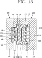
- FIGS. 13 and 14 are cross-sectional views illustrating a mold apparatus according to a third embodiment of the present invention.
- the third embodiment has a difference in which a third cooling means is added to the cavity mold plate of the first embodiment.
- a third cooling means 112 in which coolant flows is added adjacent to both sides of the cavity mold plate 110, thereby further enhancing the cooling speed of the cavity mold plate 110 together with the first cooling means 131.
- FIG. 13 is a view illustrating a state that a resin composition is injected into an inner portion of the cavity formed with the core mold plate and cavity mold plate engaged with each other and then the resin composition is cooled by the cooling plate.
- FIG. 14 is a side cross-sectional view illustrating a state prior to injecting a resin composition into an inner portion of the cavity in the third embodiment.
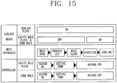
- the controller configured to control the operation of the foregoing embodiment repeatedly implements an injection process. Referring to FIG. 15 , the process of opening the core mold plate and cavity mold plate to discharge a finished product that has been injected in the prior step, and then closing the core mold plate and cavity mold plate again to form a cavity, and then injecting and cooling a resin composition and then opening the core mold plate and cavity mold plate will be repeated.
- a heater provided at the core mold plate and cavity mold plate is operated immediately after opening the core mold plate and cavity mold plate to start the heating of the core mold plate and cavity mold plate.
- the heating of the core mold plate and cavity mold plate is carried out immediately after opening the mold to reduce a time required for heating. Then, when the core mold plate and cavity mold plate are heated to a temperature suitable for injection an optimal temperature is maintained, and when the operation of injecting a resin composition is completed the operation of the heater is suspended to perform the cooling process.
- the resin composition injected through heating the core mold plate and cavity mold plate can be uniformly distributed within the cavity.
- the cooling plate 130 maintains a state of being separated from the cavity mold plate 110 as illustrated in FIG. 14 , but coolant is supplied to an inner portion of the first cooling means 131 provided at the cooling plate 130.
- coolant is preferably supplied subsequent to injecting a resin composition, but due to this the cooling of the cavity mold plate is delayed.
- coolant should be continuously supplied to the cooling plate should to always maintain a cooled state, but also be in a state of being separated from the cavity mold plate 110 as illustrated in the drawing, and thus the heating of the cavity mold plate 110 is not delayed.
- coolant is not supplied to the second and the third cooling means 212, 112.
- the cooling plate advances to the cavity mold plate as described above to indirectly cool the cavity mold plate as well as coolant is also supplied to the second and the third cooling means formed on the core mold plate and cavity mold plate, respectively, to initiate cooling.
- a time point at which coolant is supplied to the second and the third cooling means is located within the process of implementing the injection of the resin composition.
- a time required to inject a resin composition is relatively short whereas a time required to cool the core mold plate and cavity mold plate by supplying coolant is relatively long, and thus a time required for cooling can be reduced when coolant is started to be supplied while the resin composition is supplied.
- coolant is directly supplied to the cavity mold plate and core mold plate while the cavity mold plate is indirectly cooled by the cooling plate, thereby allowing rapid cooling and obtaining uniform temperature distribution. Furthermore, a relatively small number of coolant passages are disposed at the cavity mold plate disposed with the cooling plate, thereby preventing the structure of the mold from being excessively complicated, and minimizing the reduction of the mold strength due to a plurality of coolant passages.
- the cavity mold plate may be formed of any known mold steel, but may be preferably formed of a material containing a weight ratio of Be: 1.9 % and Co + Ni: 0.25 % on a copper substrate.
- the material is known as a so-called HH (Moldmax HH), and has the following physical properties.
- tempering treatment is carried out to obtain higher thermal conductivity.
- the tempering treatment is carried out by forming the cavity mold plate and then heating at temperatures of 400-500 °C and then slowly cooling down to a room temperature in the furnace.
- the tempering treatment is carried out, the hardness and tensile strength is maintained at the substantially same level, but the thermal conductivity is increased to 120 W/m ⁇ K, thereby reducing a time required for heating and cooling as well as having uniform temperature distribution even in the cavity mold plate.
- FIG. 16 is a view illustrating temperature distribution in a state that CENA-1 in the related art having a thermal conductivity of 20 W/m ⁇ K is heated and then cooled down until the maximum temperature of the cavity mold plate becomes 80 °C.
- a time required until the temperature of an external circumferential portion of the cavity mold plate becomes 80 °C is approximately 180 seconds, and temperature distribution is in a range from the minimum of 20 °C to the maximum of 80 °C. It is similar to that observed during the heating process, and highly likely that the surface quality of an injection molded article is nonuniform since the temperature difference is relatively high over the entire cavity mold plate.
- FIG. 17 is a view illustrating temperature distribution in the cavity mold plate tempered with the Moldmax HH, in which temperature distribution is similarly shown in a state of being cooled down until the maximum temperature of the cavity mold plate becomes 80 °C.
- a time required until the temperature of an external circumferential portion of the cavity mold plate becomes 80 °C is approximately 90 seconds, and therefore, about a half of that time is consumed compared to the CENA-1, and temperature distribution in a range from the minimum of 31 °C to the maximum of 76 °C is shown even in an inner portion of the cavity mold plate, and thus it is seen that temperature variation at each point is reduced compared to the CENA-1.
- a time required for cooling and heating can be reduced to a half compared to the CENA-1, but also the internal temperature of the cavity mold plate is more uniform during the heating and cooling process, thereby obtaining an effect that the surface quality of the injection molded article is uniform.
- a CrN coating layer may be formed on a surface brought into contact with the injection molded article in the mold apparatuses.
- the CrN coating layer prevents the core mold plate and cavity mold plate from being directly brought into contact with the injection molded article, thereby preventing the injection molded article from being stuck to an inner portion of the cavity.
- it may be possible to minimize the damage of the core mold plate and cavity mold plate due to corrosive gases generated in a high temperature environment.
- an injection process is carried out in a high-temperature environment to further smoothen a surface of the injection molded article, but as described above the thermal conductivity of the core mold plate and cavity mold plate should be high to improve workability and enhance process speed.
- a beryllium-based copper alloy such as the Moldmax HH, or the like, it is disadvantageous compared to a steel material such as CENA-1 in the aspect of stickability.
- the CrN (chromium nitride) coating exhibits a silver gray color, and has excellent abrasion resistance, stick resistance, thermal resistance and lubricity properties while solving the environmental problem of Cr plating.
- Tin coating has similar properties, but it is suitable to a case where the basic material is a high hardness material such as carbide, high speed tool steel, dies steel, and stainless steel, but unsuitable to a case where the basic material is relatively soft compared to the foregoing steel materials, for example, beryllium-based copper alloy.
- FIG. 18 is a graph illustrating a change of adhesive force when various surface treatment are carried out on a surface of the mold. Referring to FIG. 18 , it is seen that the surface with a CrN coating layer has an adhesive force lower than that with a TiN coating layer over the entire region between 50 and 200 °C. Accordingly, as illustrated in the above embodiment, it is seen that the CrN coating layer has the utmost performance in high-temperature injection mold having a Moldmax-based basic material.
- the CrN coating may be formed using a physical vapor disposition (hereinafter, referred to as PVD) process.
- PVD physical vapor disposition
- CVD chemical vapor deposition
- the PVD process is advantageous than the CVD process in obtaining a uniform and high-performance thin layer.
- the PVD process activates a metal material evaporated by an arc, heat, electron beam or the like in a high vacuum plasma environment, and then collides it to a target material with an acceleration energy from several tens to several thousand of eV to form a coating layer with a high hardness and high adhesiveness, and thus has features suitable to the formation of a coating layer in the mold repeatedly used for a long period of time as in the present invention.
- the PDV process has a low treatment temperature, typically less than 500 °C, and high chemical stability, thereby providing an advantage of nearly non-corrosiveness.
Landscapes
- Engineering & Computer Science (AREA)
- Manufacturing & Machinery (AREA)
- Mechanical Engineering (AREA)
- Moulds For Moulding Plastics Or The Like (AREA)
Description
- The present invention relates to an injection mold apparatus for manufacturing a resin injection molded article, and more particularly, to an injection mold apparatus having a heating means and a cooling means in the mold apparatus to heat or cool a mold during the injection process.
- Injection mold is a typical method of molding a synthetic resin such as plastic or the like. For such an injection mold, molten resin is injected and filled into a cavity of the mold formed in a certain shape and then cooled and hardened to mold a product having the same shape as the cavity.
- In general, a surface of the injection molded product is roughly formed and thus an additional painting or surface treatment process is required, and accordingly, the process becomes complicated.
- Consequently, in order to smoothen the molded surface and simplify the process, a cold mold in which injection molding is carried out and then only an outer portion of the mold is cooled down but an inner portion thereof is slowly cooled down has been developed. In this case, thermal strength can be enhanced, but the inner portion is in a low-temperature state at the initial stage even when a high-temperature mold compound is injected and thus it is difficult to maintain the temperature, thereby causing difficulty in smoothening the surface of the injection molded product.
- Accordingly, molding technologies in which injection is carried out while maintaining the mold at a high temperature and then the mold is rapidly cooled down have been studied, and as a result a high-temperature mold technology has been developed. In the high-temperature mold technology, the temperature of the mold is maintained at a high temperature by a hot wire or the like embedded in the mold to perform injection and thus resin is uniformly filled into the cavity. Furthermore, rapid cooling is uniformly carried out through a coolant passage embedded in the mold. As a result, the surface of the molded article is uniformly formed to allow the formation of a smoothened appearance. Furthermore, an additional surface treatment process is not required, thereby allowing the simplification of the process through no-painting.
- In such a high-temperature mold technology, the process of increasing the mold temperature and decreasing the mold temperature becomes a key factor for determining the surface state of the injection molded article. For the technology of decreasing the mold temperature, a cooling plate is provided at a rear surface of the cavity mold plate having a heating means, and the cooling plate is brought into contact with the cavity mold plate during the cooling process, thereby performing rapid cooling.
- Here, the cooling plate should be uniformly brought into contact with the cavity mold plate to enhance the cooling efficiency and reduce the cooling temperature variation, thereby improving the surface state of the injection molded article. However, the cavity mold plate is rapidly cooled down in a high-temperature state, and therefore thermal expansion and deformation occurs in a mass production system requiring frequent use. As a result, the cavity mold plate and the cooling plate are not uniformly brought into contact with each other, thereby causing a problem of severe cooling temperature variation.
-
US 2009/0212464 A1 describes a molding apparatus including a cavity mold with a cavity surface for defining a cavity in which a molten injection material is injected, and a core mold with a core surface for defining the cavity upon engagement with the cavity mold. The core mold has an intermediate core mold plate having the core surface and a support plate. A guide pin inserted into a guide hole formed in the cavity mold and fitted through the intermediate core mold plate to allow the intermediate core mold plate to be moved only in a forward and backward direction is fixed to the support plate. A first spring is installed between the intermediate core mold plate and the support plate, a first heating means is installed to a parting surface of the intermediate core mold plate and a cooling means is installed to the support plate.US 2011/069361 relates to injection moldings, an injection-molding apparatus and a method thereof. - The injection-molding apparatus comprises a cavity mold having a cavity, a core mold having a core surface to form a molding space for injection moldings when being joined to the cavity mold, a heating unit for heating the cavity mold or the core mold, a cooling unit for cooling the cavity mold or the core mold, and a patterning stamp having a micrometer or nanometer sized pattern and provided on an inner surface of the molding space. According to the injection-molding apparatus, a micrometer or nanometer sized pattern is formed on a surface of injection moldings so as to have a super-hydrophobic characteristic and an optical characteristic, and a micrometer or nanometer sized pattern of a complex structure can be implemented.
JP 2003 062884 A JP 2003 231165 A CN 201 721 022 U relates to a still further mold.JP H05 177640 A Figures 4 and5 ofJP H05 177640 A - The present invention is contrived to solve the foregoing problems in the related art, and an object of the present disclosure is to provide a mold apparatus capable of uniformly cooling a surface of the mold.
- Said object has been addressed with the mold apparatus according to the independent claim. Advantageous embodiments are specified in the dependent claims.
- Furthermore, another object of the present disclosure is to provide a mold apparatus capable of reducing the cooling temperature variation to decrease failure rate and ensure uniform quality.
- In addition, still another object of the present disclosure is to provide a mold apparatus capable of enhancing the cooling speed and cooling efficiency to enhance the productivity.
- According to an aspect of the present invention, there is provided a mold apparatus including a cavity mold comprising a cavity mold plate formed with a cavity at a front surface thereof and provided with a heating means at an inner portion thereof, and a cooling plate brought into contact with or separated from a rear surface of the cavity mold plate and provided with a cooling means at an inner portion thereof; and a core mold configured to determine the cavity together with the cavity mold plate, wherein the cooling plate is formed with two or more divided cooling plate parts.
- According to another aspect of the present invention, there is provided a mold apparatus including a cavity mold comprising a cavity mold plate formed with a cavity at a front surface thereof and provided with a heating means at an inner portion thereof, a base configured to support the cavity mold plate, and a cooling plate fixed between the cavity mold plate and the base to be brought into contact with or separated from the cavity mold plate and provided with a first cooling means at an inner portion thereof; a core mold provided with a core mold plate for determining the cavity together with the cavity mold plate, and including a heating means and a second cooling means disposed in the core mold plate; and a controller configured to control the operation of the heating means and cooling means, wherein the cavity mold plate includes a third cooling means.
- According to the foregoing aspects of the present invention, a cooling plate of the mold is divided and each of the divided cooling plate parts of the cooling plate is closely adhered to a rear surface of the cavity mold plate. Accordingly, a cooling temperature variation of the mold can be reduced to decrease failure rate and ensure uniform quality.
- Furthermore, according to another aspect of the present invention, a contact pressure is provided such that a cooling plate can be more uniformly adhered to the mold to reduce a cooling temperature variation of the mold and improve the cooling speed and efficiency, thereby enhancing the productivity.
- In addition, according to still another aspect of the present invention, a cooling temperature variation of the mold can be compensated in consideration of structural features of the cavity. Accordingly, it may be possible to achieve a uniform cooling temperature distribution of the mold.
- The accompanying drawings, which are included to provide a further understanding of the invention and are incorporated in and constitute a part of this specification, illustrate embodiments of the invention and together with the description serve to explain the principles of the invention.
- In the drawings:
-
FIG. 1 is a side cross-sectional view illustrating a mold apparatus according to a first embodiment of the present invention; -
FIG. 2 is a side cross-sectional view illustrating a combined state of the mold apparatus inFIG. 1 ; -
FIG. 3 is a perspective view illustrating a modified example of the first embodiment; -
FIG. 4 is a perspective view illustrating another modified example of the first embodiment; -
FIG. 5 is a perspective view illustrating that an elastic body is provided at a rear surface of the cooling plate in a mold apparatus according to the present invention; -
FIG. 6 is a graph illustrating temperature distribution based on the location of the mold in a mold apparatus in the related art; -
FIG. 7 is a graph illustrating temperature distribution based on the location of the mold in a mold apparatus according to the present invention; -
FIG. 8 is a side cross-sectional view illustrating a mold apparatus according to a second embodiment of the present invention; -
FIG. 9 is a side cross-sectional view illustrating a combined state of the mold apparatus in the second embodiment; -
FIG. 10 is an enlarged perspective view illustrating part of the second embodiment; -
FIG. 11 is a perspective view illustrating a support member according to a modified example of the second embodiment; -
FIG. 12 is a perspective view illustrating a support member according to another modified example of the second embodiment; -
FIG. 13 is a side cross-sectional view illustrating a mold apparatus according to a third embodiment of the present invention; -
FIG. 14 is a side cross-sectional view illustrating a state prior to injecting resin into an inner portion of the cavity in the third embodiment; -
FIG. 15 is a flow chart schematically illustrating an operational sequence in the third embodiment; -
FIG. 16 is a perspective view illustrating temperature distribution in the cavity mold plate with a CENA-1 material; -
FIG. 17 is a perspective view illustrating temperature distribution in the cavity mold plate with a Moldmax HH material; and -
FIG. 18 is a graph illustrating a change of adhesive force according to the surface treatment process. - Hereinafter, the detailed description of implementing the present invention will be described through an embodiment of the present invention with reference to the accompanying drawings.
-
FIG. 1 is a side cross-sectional view illustrating a mold apparatus according to a first embodiment of the present invention, andFIG. 2 is a side cross-sectional view illustrating a combined state of the mold apparatus inFIG. 1 . - Referring to
FIGS. 1 and2 , a mold apparatus according to the first embodiment includes acavity mold 100, and acore mold 200 combined with a front surface of the cavity mold plate. - The
cavity mold 100 is a fixed mold, including a cavity mold comprising acavity mold plate 110 formed with acavity 120 at afront surface 110a thereof and provided with a heating means 111 at an inner portion thereof, and acooling plate 130 brought into contact with or separated from arear surface 110b of the cavity mold plate and provided with a cooling means 131 at an inner portion thereof. Furthermore, thecavity mold 100 may include a base 140 at which the cavity mold plate is placed, anaccommodation space 150 between the cavity mold plate and the base to movably accommodate the cooling plate, and a cooling plate transfer means 160 configured to transfer the cooling plate such that the cooling plate is brought into contact with or separated from the cavity mold plate in the accommodation space. - The
cavity mold plate 110 is detachably supported and fixed to the base 140 fixed and supported by the ground or support structure (not shown) as illustrated inFIG. 1 . - The
cavity mold plate 110 is engaged with acore mold plate 210 of thecore mold 200 which will be described later to form a space of thecavity 120 capable of forming an injection moldedarticle 300, and to this end, provided with a concaved portion for forming part of thecavity 120 at afront surface 110a of thecavity mold plate 110. - The
cavity mold plate 110 may include a heating means 111 for maintaining the temperature of the mold at a high temperature to perform molding. As illustrated inFIG. 1 , the heating means 111 is embedded in a groove formed at an inner portion of the cavity mold plate, and an electric heater is typically used therefor. The heating means 111 is separated from afront surface 110a of thecavity mold plate 110 by a predetermined distance and thus unexposed on the front surface. Furthermore, a plurality of grooves in which the heating means is embedded are formed to be separated from one another along a front surface of the cavity mold plate. Accordingly, the heating means can uniformly transfer heat along the cavity in which the injection molded article is placed. - The
cooling plate 130 is provided at arear surface 110b of the cavity mold plate, and provided to be moved within theaccommodation space 150 formed between thecavity mold plate 110 andbase 140. In other words, as illustrated inFIG. 2 , when thecavity mold 100 andcore mold 200 are combined with each other, thecooling plate 130 can be moved to be brought into contact with arear surface 110b of the cavity mold plate. The movement of the cooling plate is enabled by the cooling plate transfer means 160 provided at the base to be combined with a rear surface of the cooling plate. The cooling plate transfer means 160 may be configured with a hydraulic or pneumatic device. - The
cooling plate 130 includes a first cooling means 131 disposed therein. The first cooling means 131 is provided with a cooling passage through which coolant flows formed at an inner portion of the cooling plate. The coolant is supplied to the coolant passage through acoolant supply pipe 132 connected to an outside of the cavity mold. The coolant passage is uniformly formed along the coolant passage to uniformly provide a cooling effect of the cavity mold plate by means of the cooling plate. - Meanwhile, the
cooling plate 130 may be formed with at least two or more divided coolingplate parts FIG. 3 illustrates an embodiment in which the cooling plate is divided into two surfaces, andFIG. 4 illustrates an embodiment in which the cooling plate is divided into four surfaces. However, the cooling plate in a mold apparatus according to the present invention is not limited to this, and all embodiments in which the cooling plate is divided into at least two or more surfaces are within the scope of the invention. - Referring to
FIG. 3 , thecooling plate 130 is divided into twoseparate surfaces - Referring to
FIG. 4 , thecooling plate 130 is divided into fourseparate surfaces FIG. 4 illustrates a rear surface of thecooling plate 130. InFIG. 4 , thecooling plate 130 is formed with combiningholes - Referring to
FIGS. 3 and 4 , the divided cooling plate parts are separated from one another. Accordingly, the operation of the cooling plate transfer means connected to each divided cooling plate part may be exhibited in a different manner. In other words, a height of the each divided cooling plate part being brought into contact with the cavity mold plate may be formed in a different manner by the cooling plate transfer means. - According to an aspect of the foregoing configuration, the
cooling plate 130 is divided in accordance with a rear surface of thecavity mold plate 110 such that each divided cooling plate part of the cooling plate is closely adhered to a rear surface of the cavity mold plate. - Accordingly, it may be possible to reduce the cooling temperature variation, thereby decreasing failure rate and securing uniform quality.
- On the other hand, the divides surfaces 130a, 130b, 130c, 130d, 130e, 130f may include a plurality of
elastic bodies 133 mounted between the base 140 and the surfaces.FIG. 2 illustrates a position at which the elastic body is mounted, and specifically,FIG. 5 illustrates a state in which theelastic body 133 is mounted on thecooling plate 130. - Referring to
FIG. 5 , theelastic bodies 133 are formed with coil springs, respectively, and mounted at a rear surface of thecooling plate 130. Here, theelastic bodies 133 are symmetrically mounted at each corner of the divided cooling plate parts, respectively, around the combiningholes plate parts - According to an aspect of the foregoing configuration, the each divided cooling plate part is closely adhered to a rear surface of the cavity mold plate by the cooling plate transfer means, and the elastic body forms a contact pressure, thereby allowing the divided cooling plate part to be more uniformly brought into contact therewith.
- Meanwhile, the
cooling plate 130 may be selectively combined with the divided cooling plate parts with different materials. In other words, inFIG. 3 , the first divided coolingplate part 130a and second divided coolingplate part 130b can be provided with different materials on the two divided cooling plate parts. - According to an aspect of the foregoing configuration, the divided cooling plate parts having different thermal conductivities are combined with one another to compensate the cooling temperature variation by considering that local cooling temperature variations are generated on the cavity mold plate due to a structural feature of the
cavity 120. Accordingly, it may be possible to achieve more uniform cooling temperature distribution. - On the other hand, the
core mold 200 may be provided in a movable manner to be combined with a front surface of thecavity mold plate 100. Though not shown in the drawing, a transfer means (not shown) may be connected to thebase 220 of thecore mold 200 so as to be moved toward thecavity mold plate 100, and a guide member (not shown) or the like may be also provided thereon. - The
core mold 200 is provided with thecore mold plate 210 forming thecavity 120 in accordance with the cavity mold plate, and the core mold plate is provided with additional heating means 211 and cooling means 212 disposed therein other than thecavity mold plate 100, and provided with acoolant supply pipe 213. The detailed description of the heating means, cooling means, and the like, in thecore mold plate 210 will be omitted when the description of the cavity mold plate is redundant. - A mold
compound injection pipe 310 passing through the mold is provided at thecore mold 200. Theinjection mold compound 300 injected by the mold compound injection pipe is schematically illustrated inFIG. 1 . - On the other hand, injection molding by the
cavity mold 100 andcore mold 200 is carried out as follows. The heating means 111, 211 of the cavity mold plate and core mold plate are operated in a state that thecooling plate 130 is separated from thecavity mold plate 110 as illustrated inFIG. 1 to heat the mold plates, thereby maintaining a high-temperature state. In this case, as illustrated inFIG. 2 , the cavity mold and core mold are combined with each other, and thus thecavity mold plate 110 andcore mold plate 210 form thecavity 120. - The
injection mold compound 300 is injected and filled in theheated cavity 120 in a high-temperature state. In a state that the injection mold compound is filled therein as illustrated inFIG. 2 , the cooling plate transfer means 160 is operated and thecooling plate 130 is brought into contact with a rear surface of thecavity mold plate 110. Furthermore, the first cooling means 131 of the cooling plate and the second cooling means 212 of the core mold plate are operated to perform cooling. -
FIGS. 6 and 7 illustrate temperature distribution at various points of the mold in a state that the dividedcooling plate 130 is not provided therein and in a state that the dividedcooling plate 130 is provided therein, respectively. The temperature distribution graph can be obtained by embedding thermocouples in various different positions of the cavity mold plate. - In
FIG. 6 , it is seen that temperatures are distributed in a broad range based on time at various positions of the mold in a state that the dividedcooling plate 130 is not provided therein. On the contrary, inFIG. 7 , it is seen that temperatures based on time at various positions of the mold are distributed in a narrow range in a state that the dividedcooling plate 130 is provided therein. - Since the temperature at a specific position of the mold is excessively high in the state of
FIG. 6 , the temperature that can be raised during the entire molding process is restrictive. However, the entire temperature distribution of the mold is narrowly formed in the state ofFIG. 7 and thus the temperature of the mold can be sufficiently raised. Accordingly, since the injection is carried out in a high-temperature state, a failure rate of the injection molded articles can be reduced, thereby securing uniform quality. - Furthermore, in the state of
FIG. 6 , an idle time may be required to prevent the entire temperature distribution of the mold from being increased in the middle of the repetitive mass production process. However, in the state ofFIG. 7 , temperature distribution is not large, and thus an unnecessary idle time can be reduced, thereby enhancing work efficiency or productivity. -
FIGS. 8 and9 are views illustrating a mold apparatus according to a second embodiment of the present invention. Hereinafter, the second embodiment will be described with reference toFIGS. 8 and9 , and the same elements are designated with the same numeral references and their redundant description will be omitted. - Referring to
FIGS. 8 and9 , the second embodiment may further include a support member 170 a lateral surface of which is combined with the base and the other lateral surface of which is combined with a rear surface of the cavity mold plate within theaccommodation space 150 of the first embodiment. - The
support member 170 supports thecavity mold plate 110 in a pillar shaped configuration, and has a substantially cylindrical shape. - The
support member 170 passes through thecooling plate 130 to be mounted within theaccommodation space 150. In other words, a lateral surface of thesupport member 170 is combined with thebase 140 within theaccommodation space 150 and the other lateral surface thereof is combined with arear surface 110b of the cavity mold plate. - Referring to
FIG. 10 , thecooling plate 130 is provided with a throughhole 134 through which the support member passes. Accordingly, the support member passes through the throughhole 134 to support thecavity mold plate 110 against thebase 140. Through this, a rear surface of the cavity mold plate having a low thickness is supported by a pillar shaped support member, thereby supporting the cavity mold plate against a pressure applied through a front surface of the cavity mold plate. Accordingly, it may be possible to effectively increase structural strength even if the thickness of the cavity mold plate is not high. - On the other hand, the movement of the
cooling plate 130 within the accommodation space is guided by the support member. In other words, as described above, thecooling plate 130 is moved by the cooling plate transfer means 160 within theaccommodation space 150, and thesupport member 170 may also perform the role of guiding the movement of the cooling plate. -
FIGS. 11 and12 are views illustrating the support member according to modified examples. Referring toFIG. 11 , thesupport member 170 according to an embodiment may include the coolant passage 171 formed therein. The coolant passage 171 may include at least oneparallel passages 171a in parallel to but separated from the cavity mold plate and a connectingpassage 171b for supplying and collecting coolant to and from the parallel passage. Accordingly, coolant supplied through the connecting passage flows through the parallel passage to be brought into contact with therear surface 110b of the cavity mold plate brought into contact with the support member to exchange heat, thereby cooling the cavity mold plate. - Referring to
FIG. 12 , an insulatingplate 172 may be provided at a portion brought into contact with therear surface 110b of the cavity mold plate. The insulatingplate 172 prevents the heat of the heated cavity mold plate in a high-temperature state from being transferred to the base 140 through thesupport member 170 without being heat exchanged through thecooling plate 130. Furthermore, deformation or damage due to the support member may be prevented. - Meanwhile, a plurality of
support members 170 may be provided therein. Referring toFIG. 10 , a plurality ofsupport member 170 pass through a plurality of through holes to be combined with thecooling plate 130. Here, a plurality of throughholes 133 corresponding to the number of support members are provided therein. - Preferably, the support member may be formed of a stainless steel (STS) material. Since the stainless steel has low thermal conductivity and excellent strength, the deformation or damage of the support member due to the heat of the cavity mold plate brought into contact with the support member can be reduced.
-
FIGS. 13 and14 are cross-sectional views illustrating a mold apparatus according to a third embodiment of the present invention. The third embodiment has a difference in which a third cooling means is added to the cavity mold plate of the first embodiment. In other words, a third cooling means 112 in which coolant flows is added adjacent to both sides of thecavity mold plate 110, thereby further enhancing the cooling speed of thecavity mold plate 110 together with the first cooling means 131. - Referring to
FIGS. 13 through 15 , the operation of the third embodiment will be described.FIG. 13 is a view illustrating a state that a resin composition is injected into an inner portion of the cavity formed with the core mold plate and cavity mold plate engaged with each other and then the resin composition is cooled by the cooling plate.FIG. 14 is a side cross-sectional view illustrating a state prior to injecting a resin composition into an inner portion of the cavity in the third embodiment. - The controller configured to control the operation of the foregoing embodiment repeatedly implements an injection process. Referring to
FIG. 15 , the process of opening the core mold plate and cavity mold plate to discharge a finished product that has been injected in the prior step, and then closing the core mold plate and cavity mold plate again to form a cavity, and then injecting and cooling a resin composition and then opening the core mold plate and cavity mold plate will be repeated. - At this time, a heater provided at the core mold plate and cavity mold plate is operated immediately after opening the core mold plate and cavity mold plate to start the heating of the core mold plate and cavity mold plate. In this manner, the heating of the core mold plate and cavity mold plate is carried out immediately after opening the mold to reduce a time required for heating. Then, when the core mold plate and cavity mold plate are heated to a temperature suitable for injection an optimal temperature is maintained, and when the operation of injecting a resin composition is completed the operation of the heater is suspended to perform the cooling process.
- Here, the resin composition injected through heating the core mold plate and cavity mold plate can be uniformly distributed within the cavity. During this process, the
cooling plate 130 maintains a state of being separated from thecavity mold plate 110 as illustrated inFIG. 14 , but coolant is supplied to an inner portion of the first cooling means 131 provided at thecooling plate 130. In order to rapidly heat the cavity mold plate, coolant is preferably supplied subsequent to injecting a resin composition, but due to this the cooling of the cavity mold plate is delayed. - Accordingly, coolant should be continuously supplied to the cooling plate should to always maintain a cooled state, but also be in a state of being separated from the
cavity mold plate 110 as illustrated in the drawing, and thus the heating of thecavity mold plate 110 is not delayed. At this time, coolant is not supplied to the second and the third cooling means 212, 112. When the cooling process is carried out, the cooling plate advances to the cavity mold plate as described above to indirectly cool the cavity mold plate as well as coolant is also supplied to the second and the third cooling means formed on the core mold plate and cavity mold plate, respectively, to initiate cooling. However, a time point at which coolant is supplied to the second and the third cooling means is located within the process of implementing the injection of the resin composition. In other words, a time required to inject a resin composition is relatively short whereas a time required to cool the core mold plate and cavity mold plate by supplying coolant is relatively long, and thus a time required for cooling can be reduced when coolant is started to be supplied while the resin composition is supplied. - Moreover, coolant is directly supplied to the cavity mold plate and core mold plate while the cavity mold plate is indirectly cooled by the cooling plate, thereby allowing rapid cooling and obtaining uniform temperature distribution. Furthermore, a relatively small number of coolant passages are disposed at the cavity mold plate disposed with the cooling plate, thereby preventing the structure of the mold from being excessively complicated, and minimizing the reduction of the mold strength due to a plurality of coolant passages.
- On the other hand, according to the first through the third embodiments, the cavity mold plate may be formed of any known mold steel, but may be preferably formed of a material containing a weight ratio of Be: 1.9 % and Co + Ni: 0.25 % on a copper substrate. The material is known as a so-called HH (Moldmax HH), and has the following physical properties.
- Hardness: 40 HRC
- Tensile strength: 1175 MPa
- Thermal conductivity (20 °C): 105 W/m·K
- Though the thermal conductivity has a value 5 times greater than that of the mold steel known as CENA-1 in the related art, tempering treatment is carried out to obtain higher thermal conductivity. The tempering treatment is carried out by forming the cavity mold plate and then heating at temperatures of 400-500 °C and then slowly cooling down to a room temperature in the furnace. When the tempering treatment is carried out, the hardness and tensile strength is maintained at the substantially same level, but the thermal conductivity is increased to 120 W/m·K, thereby reducing a time required for heating and cooling as well as having uniform temperature distribution even in the cavity mold plate.
-
FIG. 16 is a view illustrating temperature distribution in a state that CENA-1 in the related art having a thermal conductivity of 20 W/m·K is heated and then cooled down until the maximum temperature of the cavity mold plate becomes 80 °C. As a result of the measurement, it is seen that a time required until the temperature of an external circumferential portion of the cavity mold plate becomes 80 °C is approximately 180 seconds, and temperature distribution is in a range from the minimum of 20 °C to the maximum of 80 °C. It is similar to that observed during the heating process, and highly likely that the surface quality of an injection molded article is nonuniform since the temperature difference is relatively high over the entire cavity mold plate. -
FIG. 17 is a view illustrating temperature distribution in the cavity mold plate tempered with the Moldmax HH, in which temperature distribution is similarly shown in a state of being cooled down until the maximum temperature of the cavity mold plate becomes 80 °C. As a result of the measurement, a time required until the temperature of an external circumferential portion of the cavity mold plate becomes 80 °C is approximately 90 seconds, and therefore, about a half of that time is consumed compared to the CENA-1, and temperature distribution in a range from the minimum of 31 °C to the maximum of 76 °C is shown even in an inner portion of the cavity mold plate, and thus it is seen that temperature variation at each point is reduced compared to the CENA-1. - Accordingly, when the tempered Moldmax HH is used, a time required for cooling and heating can be reduced to a half compared to the CENA-1, but also the internal temperature of the cavity mold plate is more uniform during the heating and cooling process, thereby obtaining an effect that the surface quality of the injection molded article is uniform.
- Here, a CrN coating layer may be formed on a surface brought into contact with the injection molded article in the mold apparatuses. The CrN coating layer prevents the core mold plate and cavity mold plate from being directly brought into contact with the injection molded article, thereby preventing the injection molded article from being stuck to an inner portion of the cavity. Moreover, it may be possible to minimize the damage of the core mold plate and cavity mold plate due to corrosive gases generated in a high temperature environment.
- In particular, according to an embodiment of the present invention, an injection process is carried out in a high-temperature environment to further smoothen a surface of the injection molded article, but as described above the thermal conductivity of the core mold plate and cavity mold plate should be high to improve workability and enhance process speed. To this end, when a beryllium-based copper alloy such as the Moldmax HH, or the like, is used, it is disadvantageous compared to a steel material such as CENA-1 in the aspect of stickability.
- However, when a CrN coating layer is formed on the surface, it may be possible to improve stickability while maintaining a high thermal conductivity characteristic.
- Here, the CrN (chromium nitride) coating exhibits a silver gray color, and has excellent abrasion resistance, stick resistance, thermal resistance and lubricity properties while solving the environmental problem of Cr plating. Tin coating has similar properties, but it is suitable to a case where the basic material is a high hardness material such as carbide, high speed tool steel, dies steel, and stainless steel, but unsuitable to a case where the basic material is relatively soft compared to the foregoing steel materials, for example, beryllium-based copper alloy.
-
FIG. 18 is a graph illustrating a change of adhesive force when various surface treatment are carried out on a surface of the mold. Referring toFIG. 18 , it is seen that the surface with a CrN coating layer has an adhesive force lower than that with a TiN coating layer over the entire region between 50 and 200 °C. Accordingly, as illustrated in the above embodiment, it is seen that the CrN coating layer has the utmost performance in high-temperature injection mold having a Moldmax-based basic material. - The CrN coating may be formed using a physical vapor disposition (hereinafter, referred to as PVD) process. In addition to the PVD process, a chemical vapor deposition (hereinafter, referred to as CVD) process may be also used, but the PVD process is advantageous than the CVD process in obtaining a uniform and high-performance thin layer. In other words, the PVD process activates a metal material evaporated by an arc, heat, electron beam or the like in a high vacuum plasma environment, and then collides it to a target material with an acceleration energy from several tens to several thousand of eV to form a coating layer with a high hardness and high adhesiveness, and thus has features suitable to the formation of a coating layer in the mold repeatedly used for a long period of time as in the present invention. In particular, the PDV process has a low treatment temperature, typically less than 500 °C, and high chemical stability, thereby providing an advantage of nearly non-corrosiveness.
Claims (14)
- A mold apparatus, comprising:a cavity mold (100) comprising a cavity mold plate (110) formed with a cavity (120) at a front surface thereof and provided with a heating means (111) at an inner portion thereof, and a cooling plate (130) formed with at least two or more divided cooling plate parts (130a, 130b; 130c, 130d, 130e, 130f), which are brought into contact with or separated from a rear surface of the cavity mold plate (110), and provided with a first cooling means (131) at an inner portion thereof; anda core mold (200) configured to determine the cavity (120) together with the cavity mold plate, wherein the first cooling means (131) is provided in each of the divided cooling plate parts (130a, 130b; 130c, 130d, 130e, 130f),characterised in that the divided cooling plate parts (130a, 130b; 130c, 130d, 130e, 130f) are provided with different materials,wherein the divided cooling plate parts (130a, 130b; 130c, 130d, 130e, 130f) have different thermal conductivities.
- The mold apparatus of claim 1, wherein the cavity mold (100) further comprises:a base (140) at which the cavity mold plate (110) is placed; anda cooling plate transfer means (160) configured to transfer the cooling plate (130) such that the cooling plate (130) is brought into contact with or separated from the cavity mold plate (110) between the cavity mold plate (110) and the base (140).
- The mold apparatus of claim 2, further comprising:
elastic bodies (133) mounted between the each cooling plate (130) and the base (140). - The mold apparatus of claim 1, wherein the first cooling means (131) comprises a coolant passage formed at an inner portion of the cooling plate (130).
- The mold apparatus of claim 2, further comprising:
a support member (170) a lateral surface of which is combined with the base (140), and the other lateral surface of which is combined with a rear surface of the cavity mold plate (110). - The mold apparatus of claim 5, wherein the cooling plate (130) comprises a through hole (134) through which the support member (170) passes, and
the support member (170) is disposed in a state of being inserted in the through hole (134). - The mold apparatus of claim 5, wherein the support member (170) is provided with an insulating plate (172) at a portion combined with the cavity mold plate (110).
- The mold apparatus of claim 5, wherein a coolant passage (171) is formed at an inner portion of the support member (170).
- The mold apparatus of claim 1, wherein the cavity mold plate (110) contains a weight ratio of Be: 1.9 % and Co + Ni: 0.25 %, and is formed of a tempered beryllium-based copper alloy.
- The mold apparatus of claim 1, wherein a CrN coating layer is formed on at least one surface of the cavity mold plate (110) or core mold (200).
- The mold apparatus of claim 1, further comprising:
a second cooling means (212) provided at a core mold plate (210) of the core mold (200) and a third cooling means (112) provided at the cavity mold plate (110). - The mold apparatus of claim 11, wherein a cooling capacity of the third cooling means (112) is less than that of the first cooling means.
- The mold apparatus of claim 11, wherein an additional heating means (211) is provided in the core mold plate (210).
- The mold apparatus of claim 6, wherein the through hole (134a, 134b;/ 134c, 134d, 134e, 134f) is formed at each of the at least two divided cooling plate parts (130a, 130b; 130c, 130d, 130e, 130f).
Applications Claiming Priority (5)
| Application Number | Priority Date | Filing Date | Title |
|---|---|---|---|
| KR1020110049700A KR101821709B1 (en) | 2011-05-25 | 2011-05-25 | Die assembly |
| KR1020110049699A KR20120131494A (en) | 2011-05-25 | 2011-05-25 | Die assembly |
| KR1020110059267A KR20120139458A (en) | 2011-06-17 | 2011-06-17 | Injection mold apparatus with treated surface |
| KR1020110059266A KR20120139457A (en) | 2011-06-17 | 2011-06-17 | Injection mold apparatus |
| KR1020110060218A KR20120140464A (en) | 2011-06-21 | 2011-06-21 | Injection Molding Device |
Publications (3)
| Publication Number | Publication Date |
|---|---|
| EP2527125A2 EP2527125A2 (en) | 2012-11-28 |
| EP2527125A3 EP2527125A3 (en) | 2014-09-10 |
| EP2527125B1 true EP2527125B1 (en) | 2018-05-09 |
Family
ID=46506095
Family Applications (1)
| Application Number | Title | Priority Date | Filing Date |
|---|---|---|---|
| EP12004040.7A Not-in-force EP2527125B1 (en) | 2011-05-25 | 2012-05-24 | Mold apparatus |
Country Status (3)
| Country | Link |
|---|---|
| US (1) | US8764433B2 (en) |
| EP (1) | EP2527125B1 (en) |
| JP (1) | JP5480331B2 (en) |
Families Citing this family (19)
| Publication number | Priority date | Publication date | Assignee | Title |
|---|---|---|---|---|
| US20190118442A9 (en) * | 2010-04-20 | 2019-04-25 | Honda Motor Co., Ltd. | Conforming cooling method and mold |
| CN103057043A (en) * | 2013-01-05 | 2013-04-24 | 昆山市浩坤机械有限公司 | Plastic injection mould with cooling function |
| GB201303844D0 (en) | 2013-03-04 | 2013-04-17 | Surface Generation Ltd | Mould Tool Heat Management |
| CN105014882A (en) * | 2015-08-03 | 2015-11-04 | 江苏瑞尔光学有限公司 | PC lens forming mold |
| TWI600521B (en) * | 2016-12-19 | 2017-10-01 | 中原大學 | Molding structure and heating method thereof |
| CN110248793B (en) * | 2017-01-27 | 2021-06-11 | 本田技研工业株式会社 | Molding die |
| US12128596B2 (en) * | 2017-06-06 | 2024-10-29 | Konica Minolta, Inc. | Molding device |
| CN107553848A (en) * | 2017-09-13 | 2018-01-09 | 安徽安缆模具有限公司 | A kind of injection mold temperature precise control device |
| JP2019072923A (en) * | 2017-10-16 | 2019-05-16 | 旭化成株式会社 | Mold temperature control method and temperature control apparatus |
| CN109291373B (en) * | 2018-10-16 | 2020-10-30 | 旌德县玉屏电子电器厂(普通合伙) | A fast and intelligent device for mold injection processing |
| KR102223982B1 (en) * | 2019-08-27 | 2021-03-08 | (주)한국몰드김제 | Injection mold system for molding junction module |
| JP2021115768A (en) * | 2020-01-27 | 2021-08-10 | 株式会社アイシン | Injection molding mold |
| JP7581622B2 (en) | 2020-01-28 | 2024-11-13 | セイコーエプソン株式会社 | Injection molding device, cooling plate for injection molding device, and cassette mold |
| KR102533448B1 (en) * | 2021-10-26 | 2023-05-17 | 주식회사 서연이화 | Apparatus for heating thermocompression bonding press mold |
| CN114261056B (en) * | 2022-01-25 | 2024-07-26 | 超日(厦门)科技有限公司 | New energy high-temperature multi-metal insert in-mold injection mold and injection analysis method |
| CN114889205A (en) * | 2022-07-15 | 2022-08-12 | 常州格瑞特粉末冶金有限公司 | Water circulation cooling device for powder metallurgy forming die |
| JP2024014193A (en) * | 2022-07-22 | 2024-02-01 | アピックヤマダ株式会社 | Resin sealing device |
| CN116476343B (en) * | 2023-04-04 | 2026-03-20 | 百汇精密塑胶模具(深圳)有限公司 | An injection mold with a cooling component |
| CN119036733B (en) * | 2024-10-28 | 2025-02-07 | 晋江盟盛鞋业有限公司 | Partition cooling shoe mold and control method thereof |
Family Cites Families (18)
| Publication number | Priority date | Publication date | Assignee | Title |
|---|---|---|---|---|
| JPH01298032A (en) | 1988-05-26 | 1989-12-01 | Hitachi Ltd | Optical element press molding equipment |
| JPH04218630A (en) | 1990-12-17 | 1992-08-10 | Nikko Kyodo Co Ltd | Copper alloy for metal mold for plastic molding having high strength and high thermal conductivity and its production |
| JPH05177640A (en) * | 1991-12-27 | 1993-07-20 | Ricoh Co Ltd | Mold temperature control structure |
| JP3252819B2 (en) | 1999-01-25 | 2002-02-04 | ジェイエスアール株式会社 | Pressure control equipment and blow molding equipment |
| JP2001269966A (en) * | 2000-03-24 | 2001-10-02 | Pioneer Electronic Corp | Mold for injection molding of disk substrate |
| JP2003062884A (en) * | 2001-08-29 | 2003-03-05 | Murata Mfg Co Ltd | Injection molding device |
| JP2003231165A (en) * | 2001-11-07 | 2003-08-19 | Fuji Photo Film Co Ltd | Mold |
| JP2006150854A (en) | 2004-11-30 | 2006-06-15 | Mitsubishi Materials Corp | Mold device for optical disc molding |
| KR100644920B1 (en) * | 2005-03-24 | 2006-11-10 | 김동학 | Mold device for injection molding machine |
| EP1777049A3 (en) * | 2005-10-24 | 2012-02-08 | Samsung Electronics Co., Ltd. | Cartridge heater and molding apparatus having the same |
| JP4052600B2 (en) * | 2005-10-25 | 2008-02-27 | 山下電気株式会社 | Mold for plastic molding |
| KR101273591B1 (en) * | 2007-01-22 | 2013-06-11 | 삼성전자주식회사 | Injection molding device |
| CN101765489B (en) * | 2007-08-28 | 2013-05-08 | Lg电子株式会社 | Injection moldings, injection-molding apparatus and method thereof |
| KR20100033704A (en) | 2008-09-22 | 2010-03-31 | 엘지전자 주식회사 | Stamper with fine pattern |
| TWI389600B (en) * | 2008-12-19 | 2013-03-11 | 私立中原大學 | Coaxial cooling and rapid conductive coil construction and molds with cobalt cooling and rapid conductive coil construction |
| US8540503B2 (en) * | 2009-09-09 | 2013-09-24 | Panasonic Corporation | Disk substrate molding apparatus, disk substrate molding method and disk substrate molding die |
| US8741193B2 (en) * | 2010-03-18 | 2014-06-03 | Mitsubishi Heavy Industries Plastic Technology Co., Ltd. | Injection molding method, molded-article producing method, and injection molding apparatus |
| CN201721022U (en) * | 2010-05-18 | 2011-01-26 | 山东大学 | Electrothermic and floating rapid heating cycle injection mold |
-
2012
- 2012-05-24 EP EP12004040.7A patent/EP2527125B1/en not_active Not-in-force
- 2012-05-25 JP JP2012120128A patent/JP5480331B2/en not_active Expired - Fee Related
- 2012-05-25 US US13/480,962 patent/US8764433B2/en active Active
Non-Patent Citations (1)
| Title |
|---|
| None * |
Also Published As
| Publication number | Publication date |
|---|---|
| EP2527125A2 (en) | 2012-11-28 |
| US8764433B2 (en) | 2014-07-01 |
| JP5480331B2 (en) | 2014-04-23 |
| US20120301571A1 (en) | 2012-11-29 |
| EP2527125A3 (en) | 2014-09-10 |
| JP2012245783A (en) | 2012-12-13 |
Similar Documents
| Publication | Publication Date | Title |
|---|---|---|
| EP2527125A2 (en) | Mold apparatus | |
| US10155350B2 (en) | Mold insert for improved heat transfer | |
| US5062786A (en) | Molding device for molding optical elements | |
| CN101132898A (en) | Molds for injection molding machines | |
| JP5708640B2 (en) | Mold and mold manufacturing method | |
| WO2004039517A1 (en) | Mold for casting and method of surface treatment thereof | |
| WO2008008703A2 (en) | Compound tooling for controlled work surface characteristics | |
| JP2009073185A (en) | Mold for thin plate molded article | |
| KR101821709B1 (en) | Die assembly | |
| WO2018023168A1 (en) | A multi material laminated tool having improved thermal coupling | |
| JP2008149499A (en) | Injection mold | |
| JP2009202549A (en) | Production process of resin molded article | |
| JP2010036495A (en) | Injection compression molding mold | |
| JP5234640B2 (en) | Ultra-thin light guide plate molding die and molding method | |
| JP2009137154A (en) | Injection mold | |
| JP2024520991A (en) | Tool insert for a primary moulding tool and primary moulding tool equipped with said tool insert | |
| JP2009172813A (en) | Molding method of optical molded article | |
| CN101426634A (en) | Disk molding die, mirror surface disk, and method for manufacturing mirror surface disk | |
| JPH0237953A (en) | Casting equipment using cast pins | |
| KR100566147B1 (en) | Injection molding equipment, component member used for the same, and surface treatment method | |
| JP2010201866A (en) | Metal mold device, heat insulating member and method of manufacturing metal mold device | |
| JPWO2008053732A1 (en) | Mold for molding and manufacturing method thereof | |
| JP2014046537A (en) | Sprue bush and molding die | |
| JP3367915B2 (en) | Metal injection molding method | |
| KR20120139458A (en) | Injection mold apparatus with treated surface |
Legal Events
| Date | Code | Title | Description |
|---|---|---|---|
| PUAI | Public reference made under article 153(3) epc to a published international application that has entered the european phase |
Free format text: ORIGINAL CODE: 0009012 |
|
| AK | Designated contracting states |
Kind code of ref document: A2 Designated state(s): AL AT BE BG CH CY CZ DE DK EE ES FI FR GB GR HR HU IE IS IT LI LT LU LV MC MK MT NL NO PL PT RO RS SE SI SK SM TR |
|
| AX | Request for extension of the european patent |
Extension state: BA ME |
|
| PUAL | Search report despatched |
Free format text: ORIGINAL CODE: 0009013 |
|
| AK | Designated contracting states |
Kind code of ref document: A3 Designated state(s): AL AT BE BG CH CY CZ DE DK EE ES FI FR GB GR HR HU IE IS IT LI LT LU LV MC MK MT NL NO PL PT RO RS SE SI SK SM TR |
|
| AX | Request for extension of the european patent |
Extension state: BA ME |
|
| RIC1 | Information provided on ipc code assigned before grant |
Ipc: B29C 45/73 20060101AFI20140807BHEP |
|
| 17P | Request for examination filed |
Effective date: 20150203 |
|
| RBV | Designated contracting states (corrected) |
Designated state(s): AL AT BE BG CH CY CZ DE DK EE ES FI FR GB GR HR HU IE IS IT LI LT LU LV MC MK MT NL NO PL PT RO RS SE SI SK SM TR |
|
| 17Q | First examination report despatched |
Effective date: 20160502 |
|
| GRAP | Despatch of communication of intention to grant a patent |
Free format text: ORIGINAL CODE: EPIDOSNIGR1 |
|
| INTG | Intention to grant announced |
Effective date: 20171220 |
|
| RAP1 | Party data changed (applicant data changed or rights of an application transferred) |
Owner name: LG ELECTRONICS INC. |
|
| GRAS | Grant fee paid |
Free format text: ORIGINAL CODE: EPIDOSNIGR3 |
|
| GRAA | (expected) grant |
Free format text: ORIGINAL CODE: 0009210 |
|
| AK | Designated contracting states |
Kind code of ref document: B1 Designated state(s): AL AT BE BG CH CY CZ DE DK EE ES FI FR GB GR HR HU IE IS IT LI LT LU LV MC MK MT NL NO PL PT RO RS SE SI SK SM TR |
|
| REG | Reference to a national code |
Ref country code: GB Ref legal event code: FG4D |
|
| REG | Reference to a national code |
Ref country code: CH Ref legal event code: EP Ref country code: AT Ref legal event code: REF Ref document number: 997191 Country of ref document: AT Kind code of ref document: T Effective date: 20180515 |
|
| REG | Reference to a national code |
Ref country code: IE Ref legal event code: FG4D |
|
| REG | Reference to a national code |
Ref country code: DE Ref legal event code: R096 Ref document number: 602012046096 Country of ref document: DE |
|
| REG | Reference to a national code |
Ref country code: NL Ref legal event code: MP Effective date: 20180509 |
|
| REG | Reference to a national code |
Ref country code: LT Ref legal event code: MG4D |
|
| PG25 | Lapsed in a contracting state [announced via postgrant information from national office to epo] |
Ref country code: ES Free format text: LAPSE BECAUSE OF FAILURE TO SUBMIT A TRANSLATION OF THE DESCRIPTION OR TO PAY THE FEE WITHIN THE PRESCRIBED TIME-LIMIT Effective date: 20180509 Ref country code: SE Free format text: LAPSE BECAUSE OF FAILURE TO SUBMIT A TRANSLATION OF THE DESCRIPTION OR TO PAY THE FEE WITHIN THE PRESCRIBED TIME-LIMIT Effective date: 20180509 Ref country code: LT Free format text: LAPSE BECAUSE OF FAILURE TO SUBMIT A TRANSLATION OF THE DESCRIPTION OR TO PAY THE FEE WITHIN THE PRESCRIBED TIME-LIMIT Effective date: 20180509 Ref country code: NO Free format text: LAPSE BECAUSE OF FAILURE TO SUBMIT A TRANSLATION OF THE DESCRIPTION OR TO PAY THE FEE WITHIN THE PRESCRIBED TIME-LIMIT Effective date: 20180809 Ref country code: FI Free format text: LAPSE BECAUSE OF FAILURE TO SUBMIT A TRANSLATION OF THE DESCRIPTION OR TO PAY THE FEE WITHIN THE PRESCRIBED TIME-LIMIT Effective date: 20180509 Ref country code: BG Free format text: LAPSE BECAUSE OF FAILURE TO SUBMIT A TRANSLATION OF THE DESCRIPTION OR TO PAY THE FEE WITHIN THE PRESCRIBED TIME-LIMIT Effective date: 20180809 |
|
| PG25 | Lapsed in a contracting state [announced via postgrant information from national office to epo] |
Ref country code: RS Free format text: LAPSE BECAUSE OF FAILURE TO SUBMIT A TRANSLATION OF THE DESCRIPTION OR TO PAY THE FEE WITHIN THE PRESCRIBED TIME-LIMIT Effective date: 20180509 Ref country code: GR Free format text: LAPSE BECAUSE OF FAILURE TO SUBMIT A TRANSLATION OF THE DESCRIPTION OR TO PAY THE FEE WITHIN THE PRESCRIBED TIME-LIMIT Effective date: 20180810 Ref country code: LV Free format text: LAPSE BECAUSE OF FAILURE TO SUBMIT A TRANSLATION OF THE DESCRIPTION OR TO PAY THE FEE WITHIN THE PRESCRIBED TIME-LIMIT Effective date: 20180509 Ref country code: NL Free format text: LAPSE BECAUSE OF FAILURE TO SUBMIT A TRANSLATION OF THE DESCRIPTION OR TO PAY THE FEE WITHIN THE PRESCRIBED TIME-LIMIT Effective date: 20180509 Ref country code: HR Free format text: LAPSE BECAUSE OF FAILURE TO SUBMIT A TRANSLATION OF THE DESCRIPTION OR TO PAY THE FEE WITHIN THE PRESCRIBED TIME-LIMIT Effective date: 20180509 |
|
| REG | Reference to a national code |
Ref country code: CH Ref legal event code: PL |
|
| REG | Reference to a national code |
Ref country code: AT Ref legal event code: MK05 Ref document number: 997191 Country of ref document: AT Kind code of ref document: T Effective date: 20180509 |
|
| REG | Reference to a national code |
Ref country code: BE Ref legal event code: MM Effective date: 20180531 |
|
| PG25 | Lapsed in a contracting state [announced via postgrant information from national office to epo] |
Ref country code: SK Free format text: LAPSE BECAUSE OF FAILURE TO SUBMIT A TRANSLATION OF THE DESCRIPTION OR TO PAY THE FEE WITHIN THE PRESCRIBED TIME-LIMIT Effective date: 20180509 Ref country code: PL Free format text: LAPSE BECAUSE OF FAILURE TO SUBMIT A TRANSLATION OF THE DESCRIPTION OR TO PAY THE FEE WITHIN THE PRESCRIBED TIME-LIMIT Effective date: 20180509 Ref country code: DK Free format text: LAPSE BECAUSE OF FAILURE TO SUBMIT A TRANSLATION OF THE DESCRIPTION OR TO PAY THE FEE WITHIN THE PRESCRIBED TIME-LIMIT Effective date: 20180509 Ref country code: AT Free format text: LAPSE BECAUSE OF FAILURE TO SUBMIT A TRANSLATION OF THE DESCRIPTION OR TO PAY THE FEE WITHIN THE PRESCRIBED TIME-LIMIT Effective date: 20180509 Ref country code: EE Free format text: LAPSE BECAUSE OF FAILURE TO SUBMIT A TRANSLATION OF THE DESCRIPTION OR TO PAY THE FEE WITHIN THE PRESCRIBED TIME-LIMIT Effective date: 20180509 Ref country code: RO Free format text: LAPSE BECAUSE OF FAILURE TO SUBMIT A TRANSLATION OF THE DESCRIPTION OR TO PAY THE FEE WITHIN THE PRESCRIBED TIME-LIMIT Effective date: 20180509 Ref country code: CZ Free format text: LAPSE BECAUSE OF FAILURE TO SUBMIT A TRANSLATION OF THE DESCRIPTION OR TO PAY THE FEE WITHIN THE PRESCRIBED TIME-LIMIT Effective date: 20180509 |
|
| REG | Reference to a national code |
Ref country code: DE Ref legal event code: R097 Ref document number: 602012046096 Country of ref document: DE |
|
| REG | Reference to a national code |
Ref country code: IE Ref legal event code: MM4A |
|
| PG25 | Lapsed in a contracting state [announced via postgrant information from national office to epo] |
Ref country code: CH Free format text: LAPSE BECAUSE OF NON-PAYMENT OF DUE FEES Effective date: 20180531 Ref country code: IT Free format text: LAPSE BECAUSE OF FAILURE TO SUBMIT A TRANSLATION OF THE DESCRIPTION OR TO PAY THE FEE WITHIN THE PRESCRIBED TIME-LIMIT Effective date: 20180509 Ref country code: SM Free format text: LAPSE BECAUSE OF FAILURE TO SUBMIT A TRANSLATION OF THE DESCRIPTION OR TO PAY THE FEE WITHIN THE PRESCRIBED TIME-LIMIT Effective date: 20180509 Ref country code: LI Free format text: LAPSE BECAUSE OF NON-PAYMENT OF DUE FEES Effective date: 20180531 |
|
| PLBE | No opposition filed within time limit |
Free format text: ORIGINAL CODE: 0009261 |
|
| STAA | Information on the status of an ep patent application or granted ep patent |
Free format text: STATUS: NO OPPOSITION FILED WITHIN TIME LIMIT |
|
| PG25 | Lapsed in a contracting state [announced via postgrant information from national office to epo] |
Ref country code: MC Free format text: LAPSE BECAUSE OF FAILURE TO SUBMIT A TRANSLATION OF THE DESCRIPTION OR TO PAY THE FEE WITHIN THE PRESCRIBED TIME-LIMIT Effective date: 20180509 Ref country code: LU Free format text: LAPSE BECAUSE OF NON-PAYMENT OF DUE FEES Effective date: 20180524 |
|
| 26N | No opposition filed |
Effective date: 20190212 |
|
| GBPC | Gb: european patent ceased through non-payment of renewal fee |
Effective date: 20180809 |
|
| PG25 | Lapsed in a contracting state [announced via postgrant information from national office to epo] |
Ref country code: IE Free format text: LAPSE BECAUSE OF NON-PAYMENT OF DUE FEES Effective date: 20180524 Ref country code: FR Free format text: LAPSE BECAUSE OF NON-PAYMENT OF DUE FEES Effective date: 20180709 |
|
| PG25 | Lapsed in a contracting state [announced via postgrant information from national office to epo] |
Ref country code: BE Free format text: LAPSE BECAUSE OF NON-PAYMENT OF DUE FEES Effective date: 20180531 Ref country code: SI Free format text: LAPSE BECAUSE OF FAILURE TO SUBMIT A TRANSLATION OF THE DESCRIPTION OR TO PAY THE FEE WITHIN THE PRESCRIBED TIME-LIMIT Effective date: 20180509 |
|
| PG25 | Lapsed in a contracting state [announced via postgrant information from national office to epo] |
Ref country code: GB Free format text: LAPSE BECAUSE OF NON-PAYMENT OF DUE FEES Effective date: 20180809 |
|
| PG25 | Lapsed in a contracting state [announced via postgrant information from national office to epo] |
Ref country code: AL Free format text: LAPSE BECAUSE OF FAILURE TO SUBMIT A TRANSLATION OF THE DESCRIPTION OR TO PAY THE FEE WITHIN THE PRESCRIBED TIME-LIMIT Effective date: 20180509 |
|
| PG25 | Lapsed in a contracting state [announced via postgrant information from national office to epo] |
Ref country code: MT Free format text: LAPSE BECAUSE OF NON-PAYMENT OF DUE FEES Effective date: 20180524 |
|
| PG25 | Lapsed in a contracting state [announced via postgrant information from national office to epo] |
Ref country code: TR Free format text: LAPSE BECAUSE OF FAILURE TO SUBMIT A TRANSLATION OF THE DESCRIPTION OR TO PAY THE FEE WITHIN THE PRESCRIBED TIME-LIMIT Effective date: 20180509 |
|
| PG25 | Lapsed in a contracting state [announced via postgrant information from national office to epo] |
Ref country code: HU Free format text: LAPSE BECAUSE OF FAILURE TO SUBMIT A TRANSLATION OF THE DESCRIPTION OR TO PAY THE FEE WITHIN THE PRESCRIBED TIME-LIMIT; INVALID AB INITIO Effective date: 20120524 Ref country code: PT Free format text: LAPSE BECAUSE OF FAILURE TO SUBMIT A TRANSLATION OF THE DESCRIPTION OR TO PAY THE FEE WITHIN THE PRESCRIBED TIME-LIMIT Effective date: 20180509 |
|
| PG25 | Lapsed in a contracting state [announced via postgrant information from national office to epo] |
Ref country code: CY Free format text: LAPSE BECAUSE OF FAILURE TO SUBMIT A TRANSLATION OF THE DESCRIPTION OR TO PAY THE FEE WITHIN THE PRESCRIBED TIME-LIMIT Effective date: 20180509 Ref country code: MK Free format text: LAPSE BECAUSE OF NON-PAYMENT OF DUE FEES Effective date: 20180509 |
|
| PG25 | Lapsed in a contracting state [announced via postgrant information from national office to epo] |
Ref country code: IS Free format text: LAPSE BECAUSE OF FAILURE TO SUBMIT A TRANSLATION OF THE DESCRIPTION OR TO PAY THE FEE WITHIN THE PRESCRIBED TIME-LIMIT Effective date: 20180909 |
|
| PGFP | Annual fee paid to national office [announced via postgrant information from national office to epo] |
Ref country code: DE Payment date: 20220405 Year of fee payment: 11 |
|
| REG | Reference to a national code |
Ref country code: DE Ref legal event code: R119 Ref document number: 602012046096 Country of ref document: DE |
|
| PG25 | Lapsed in a contracting state [announced via postgrant information from national office to epo] |
Ref country code: DE Free format text: LAPSE BECAUSE OF NON-PAYMENT OF DUE FEES Effective date: 20231201 |