EP2527077A1 - Method for repairing wall member with passage - Google Patents
Method for repairing wall member with passage Download PDFInfo
- Publication number
- EP2527077A1 EP2527077A1 EP11734564A EP11734564A EP2527077A1 EP 2527077 A1 EP2527077 A1 EP 2527077A1 EP 11734564 A EP11734564 A EP 11734564A EP 11734564 A EP11734564 A EP 11734564A EP 2527077 A1 EP2527077 A1 EP 2527077A1
- Authority
- EP
- European Patent Office
- Prior art keywords
- welding
- repairing
- flow passages
- wall member
- overlay
- Prior art date
- Legal status (The legal status is an assumption and is not a legal conclusion. Google has not performed a legal analysis and makes no representation as to the accuracy of the status listed.)
- Granted
Links
Images


Classifications
-
- B—PERFORMING OPERATIONS; TRANSPORTING
- B23—MACHINE TOOLS; METAL-WORKING NOT OTHERWISE PROVIDED FOR
- B23K—SOLDERING OR UNSOLDERING; WELDING; CLADDING OR PLATING BY SOLDERING OR WELDING; CUTTING BY APPLYING HEAT LOCALLY, e.g. FLAME CUTTING; WORKING BY LASER BEAM
- B23K26/00—Working by laser beam, e.g. welding, cutting or boring
- B23K26/20—Bonding
- B23K26/21—Bonding by welding
-
- B—PERFORMING OPERATIONS; TRANSPORTING
- B23—MACHINE TOOLS; METAL-WORKING NOT OTHERWISE PROVIDED FOR
- B23P—METAL-WORKING NOT OTHERWISE PROVIDED FOR; COMBINED OPERATIONS; UNIVERSAL MACHINE TOOLS
- B23P6/00—Restoring or reconditioning objects
- B23P6/002—Repairing turbine components, e.g. moving or stationary blades, rotors
-
- B—PERFORMING OPERATIONS; TRANSPORTING
- B23—MACHINE TOOLS; METAL-WORKING NOT OTHERWISE PROVIDED FOR
- B23K—SOLDERING OR UNSOLDERING; WELDING; CLADDING OR PLATING BY SOLDERING OR WELDING; CUTTING BY APPLYING HEAT LOCALLY, e.g. FLAME CUTTING; WORKING BY LASER BEAM
- B23K10/00—Welding or cutting by means of a plasma
- B23K10/02—Plasma welding
- B23K10/027—Welding for purposes other than joining, e.g. build-up welding
-
- B—PERFORMING OPERATIONS; TRANSPORTING
- B23—MACHINE TOOLS; METAL-WORKING NOT OTHERWISE PROVIDED FOR
- B23K—SOLDERING OR UNSOLDERING; WELDING; CLADDING OR PLATING BY SOLDERING OR WELDING; CUTTING BY APPLYING HEAT LOCALLY, e.g. FLAME CUTTING; WORKING BY LASER BEAM
- B23K15/00—Electron-beam welding or cutting
-
- B—PERFORMING OPERATIONS; TRANSPORTING
- B23—MACHINE TOOLS; METAL-WORKING NOT OTHERWISE PROVIDED FOR
- B23K—SOLDERING OR UNSOLDERING; WELDING; CLADDING OR PLATING BY SOLDERING OR WELDING; CUTTING BY APPLYING HEAT LOCALLY, e.g. FLAME CUTTING; WORKING BY LASER BEAM
- B23K15/00—Electron-beam welding or cutting
- B23K15/0046—Welding
- B23K15/0086—Welding welding for purposes other than joining, e.g. build-up welding
-
- B—PERFORMING OPERATIONS; TRANSPORTING
- B23—MACHINE TOOLS; METAL-WORKING NOT OTHERWISE PROVIDED FOR
- B23K—SOLDERING OR UNSOLDERING; WELDING; CLADDING OR PLATING BY SOLDERING OR WELDING; CUTTING BY APPLYING HEAT LOCALLY, e.g. FLAME CUTTING; WORKING BY LASER BEAM
- B23K26/00—Working by laser beam, e.g. welding, cutting or boring
- B23K26/14—Working by laser beam, e.g. welding, cutting or boring using a fluid stream, e.g. a jet of gas, in conjunction with the laser beam; Nozzles therefor
- B23K26/142—Working by laser beam, e.g. welding, cutting or boring using a fluid stream, e.g. a jet of gas, in conjunction with the laser beam; Nozzles therefor for the removal of by-products
-
- B—PERFORMING OPERATIONS; TRANSPORTING
- B23—MACHINE TOOLS; METAL-WORKING NOT OTHERWISE PROVIDED FOR
- B23K—SOLDERING OR UNSOLDERING; WELDING; CLADDING OR PLATING BY SOLDERING OR WELDING; CUTTING BY APPLYING HEAT LOCALLY, e.g. FLAME CUTTING; WORKING BY LASER BEAM
- B23K26/00—Working by laser beam, e.g. welding, cutting or boring
- B23K26/14—Working by laser beam, e.g. welding, cutting or boring using a fluid stream, e.g. a jet of gas, in conjunction with the laser beam; Nozzles therefor
- B23K26/144—Working by laser beam, e.g. welding, cutting or boring using a fluid stream, e.g. a jet of gas, in conjunction with the laser beam; Nozzles therefor the fluid stream containing particles, e.g. powder
-
- B—PERFORMING OPERATIONS; TRANSPORTING
- B23—MACHINE TOOLS; METAL-WORKING NOT OTHERWISE PROVIDED FOR
- B23K—SOLDERING OR UNSOLDERING; WELDING; CLADDING OR PLATING BY SOLDERING OR WELDING; CUTTING BY APPLYING HEAT LOCALLY, e.g. FLAME CUTTING; WORKING BY LASER BEAM
- B23K26/00—Working by laser beam, e.g. welding, cutting or boring
- B23K26/20—Bonding
- B23K26/32—Bonding taking account of the properties of the material involved
-
- B—PERFORMING OPERATIONS; TRANSPORTING
- B23—MACHINE TOOLS; METAL-WORKING NOT OTHERWISE PROVIDED FOR
- B23K—SOLDERING OR UNSOLDERING; WELDING; CLADDING OR PLATING BY SOLDERING OR WELDING; CUTTING BY APPLYING HEAT LOCALLY, e.g. FLAME CUTTING; WORKING BY LASER BEAM
- B23K26/00—Working by laser beam, e.g. welding, cutting or boring
- B23K26/20—Bonding
- B23K26/32—Bonding taking account of the properties of the material involved
- B23K26/322—Bonding taking account of the properties of the material involved involving coated metal parts
-
- B—PERFORMING OPERATIONS; TRANSPORTING
- B23—MACHINE TOOLS; METAL-WORKING NOT OTHERWISE PROVIDED FOR
- B23K—SOLDERING OR UNSOLDERING; WELDING; CLADDING OR PLATING BY SOLDERING OR WELDING; CUTTING BY APPLYING HEAT LOCALLY, e.g. FLAME CUTTING; WORKING BY LASER BEAM
- B23K26/00—Working by laser beam, e.g. welding, cutting or boring
- B23K26/20—Bonding
- B23K26/32—Bonding taking account of the properties of the material involved
- B23K26/323—Bonding taking account of the properties of the material involved involving parts made of dissimilar metallic material
-
- B—PERFORMING OPERATIONS; TRANSPORTING
- B23—MACHINE TOOLS; METAL-WORKING NOT OTHERWISE PROVIDED FOR
- B23K—SOLDERING OR UNSOLDERING; WELDING; CLADDING OR PLATING BY SOLDERING OR WELDING; CUTTING BY APPLYING HEAT LOCALLY, e.g. FLAME CUTTING; WORKING BY LASER BEAM
- B23K26/00—Working by laser beam, e.g. welding, cutting or boring
- B23K26/34—Laser welding for purposes other than joining
-
- B—PERFORMING OPERATIONS; TRANSPORTING
- B23—MACHINE TOOLS; METAL-WORKING NOT OTHERWISE PROVIDED FOR
- B23K—SOLDERING OR UNSOLDERING; WELDING; CLADDING OR PLATING BY SOLDERING OR WELDING; CUTTING BY APPLYING HEAT LOCALLY, e.g. FLAME CUTTING; WORKING BY LASER BEAM
- B23K26/00—Working by laser beam, e.g. welding, cutting or boring
- B23K26/34—Laser welding for purposes other than joining
- B23K26/342—Build-up welding
-
- B—PERFORMING OPERATIONS; TRANSPORTING
- B23—MACHINE TOOLS; METAL-WORKING NOT OTHERWISE PROVIDED FOR
- B23K—SOLDERING OR UNSOLDERING; WELDING; CLADDING OR PLATING BY SOLDERING OR WELDING; CUTTING BY APPLYING HEAT LOCALLY, e.g. FLAME CUTTING; WORKING BY LASER BEAM
- B23K26/00—Working by laser beam, e.g. welding, cutting or boring
- B23K26/346—Working by laser beam, e.g. welding, cutting or boring in combination with welding or cutting covered by groups B23K5/00 - B23K25/00, e.g. in combination with resistance welding
-
- B—PERFORMING OPERATIONS; TRANSPORTING
- B23—MACHINE TOOLS; METAL-WORKING NOT OTHERWISE PROVIDED FOR
- B23K—SOLDERING OR UNSOLDERING; WELDING; CLADDING OR PLATING BY SOLDERING OR WELDING; CUTTING BY APPLYING HEAT LOCALLY, e.g. FLAME CUTTING; WORKING BY LASER BEAM
- B23K35/00—Rods, electrodes, materials, or media, for use in soldering, welding, or cutting
- B23K35/02—Rods, electrodes, materials, or media, for use in soldering, welding, or cutting characterised by mechanical features, e.g. shape
- B23K35/0222—Rods, electrodes, materials, or media, for use in soldering, welding, or cutting characterised by mechanical features, e.g. shape for use in soldering or brazing
- B23K35/0244—Powders, particles or spheres; Preforms made therefrom
-
- B—PERFORMING OPERATIONS; TRANSPORTING
- B23—MACHINE TOOLS; METAL-WORKING NOT OTHERWISE PROVIDED FOR
- B23K—SOLDERING OR UNSOLDERING; WELDING; CLADDING OR PLATING BY SOLDERING OR WELDING; CUTTING BY APPLYING HEAT LOCALLY, e.g. FLAME CUTTING; WORKING BY LASER BEAM
- B23K35/00—Rods, electrodes, materials, or media, for use in soldering, welding, or cutting
- B23K35/22—Rods, electrodes, materials, or media, for use in soldering, welding, or cutting characterised by the composition or nature of the material
- B23K35/24—Selection of soldering or welding materials proper
- B23K35/30—Selection of soldering or welding materials proper with the principal constituent melting at less than 1550°C
- B23K35/3033—Ni as the principal constituent
-
- B—PERFORMING OPERATIONS; TRANSPORTING
- B23—MACHINE TOOLS; METAL-WORKING NOT OTHERWISE PROVIDED FOR
- B23K—SOLDERING OR UNSOLDERING; WELDING; CLADDING OR PLATING BY SOLDERING OR WELDING; CUTTING BY APPLYING HEAT LOCALLY, e.g. FLAME CUTTING; WORKING BY LASER BEAM
- B23K9/00—Arc welding or cutting
- B23K9/04—Welding for other purposes than joining, e.g. built-up welding
- B23K9/044—Built-up welding on three-dimensional surfaces
-
- F—MECHANICAL ENGINEERING; LIGHTING; HEATING; WEAPONS; BLASTING
- F01—MACHINES OR ENGINES IN GENERAL; ENGINE PLANTS IN GENERAL; STEAM ENGINES
- F01D—NON-POSITIVE DISPLACEMENT MACHINES OR ENGINES, e.g. STEAM TURBINES
- F01D25/00—Component parts, details, or accessories, not provided for in, or of interest apart from, other groups
- F01D25/28—Supporting or mounting arrangements, e.g. for turbine casing
- F01D25/285—Temporary support structures, e.g. for testing, assembling, installing, repairing; Assembly methods using such structures
-
- F—MECHANICAL ENGINEERING; LIGHTING; HEATING; WEAPONS; BLASTING
- F02—COMBUSTION ENGINES; HOT-GAS OR COMBUSTION-PRODUCT ENGINE PLANTS
- F02C—GAS-TURBINE PLANTS; AIR INTAKES FOR JET-PROPULSION PLANTS; CONTROLLING FUEL SUPPLY IN AIR-BREATHING JET-PROPULSION PLANTS
- F02C7/00—Features, components parts, details or accessories, not provided for in, or of interest apart form groups F02C1/00 - F02C6/00; Air intakes for jet-propulsion plants
-
- B—PERFORMING OPERATIONS; TRANSPORTING
- B23—MACHINE TOOLS; METAL-WORKING NOT OTHERWISE PROVIDED FOR
- B23K—SOLDERING OR UNSOLDERING; WELDING; CLADDING OR PLATING BY SOLDERING OR WELDING; CUTTING BY APPLYING HEAT LOCALLY, e.g. FLAME CUTTING; WORKING BY LASER BEAM
- B23K2101/00—Articles made by soldering, welding or cutting
- B23K2101/001—Turbines
-
- B—PERFORMING OPERATIONS; TRANSPORTING
- B23—MACHINE TOOLS; METAL-WORKING NOT OTHERWISE PROVIDED FOR
- B23K—SOLDERING OR UNSOLDERING; WELDING; CLADDING OR PLATING BY SOLDERING OR WELDING; CUTTING BY APPLYING HEAT LOCALLY, e.g. FLAME CUTTING; WORKING BY LASER BEAM
- B23K2101/00—Articles made by soldering, welding or cutting
- B23K2101/34—Coated articles ; Surface treated articles
-
- B—PERFORMING OPERATIONS; TRANSPORTING
- B23—MACHINE TOOLS; METAL-WORKING NOT OTHERWISE PROVIDED FOR
- B23K—SOLDERING OR UNSOLDERING; WELDING; CLADDING OR PLATING BY SOLDERING OR WELDING; CUTTING BY APPLYING HEAT LOCALLY, e.g. FLAME CUTTING; WORKING BY LASER BEAM
- B23K2103/00—Materials to be soldered, welded or cut
- B23K2103/08—Non-ferrous metals or alloys
-
- B—PERFORMING OPERATIONS; TRANSPORTING
- B23—MACHINE TOOLS; METAL-WORKING NOT OTHERWISE PROVIDED FOR
- B23K—SOLDERING OR UNSOLDERING; WELDING; CLADDING OR PLATING BY SOLDERING OR WELDING; CUTTING BY APPLYING HEAT LOCALLY, e.g. FLAME CUTTING; WORKING BY LASER BEAM
- B23K2103/00—Materials to be soldered, welded or cut
- B23K2103/18—Dissimilar materials
- B23K2103/26—Alloys of Nickel and Cobalt and Chromium
-
- B—PERFORMING OPERATIONS; TRANSPORTING
- B23—MACHINE TOOLS; METAL-WORKING NOT OTHERWISE PROVIDED FOR
- B23P—METAL-WORKING NOT OTHERWISE PROVIDED FOR; COMBINED OPERATIONS; UNIVERSAL MACHINE TOOLS
- B23P2700/00—Indexing scheme relating to the articles being treated, e.g. manufactured, repaired, assembled, connected or other operations covered in the subgroups
- B23P2700/13—Parts of turbine combustion chambers
-
- F—MECHANICAL ENGINEERING; LIGHTING; HEATING; WEAPONS; BLASTING
- F05—INDEXING SCHEMES RELATING TO ENGINES OR PUMPS IN VARIOUS SUBCLASSES OF CLASSES F01-F04
- F05D—INDEXING SCHEME FOR ASPECTS RELATING TO NON-POSITIVE-DISPLACEMENT MACHINES OR ENGINES, GAS-TURBINES OR JET-PROPULSION PLANTS
- F05D2230/00—Manufacture
- F05D2230/20—Manufacture essentially without removing material
- F05D2230/23—Manufacture essentially without removing material by permanently joining parts together
- F05D2230/232—Manufacture essentially without removing material by permanently joining parts together by welding
-
- F—MECHANICAL ENGINEERING; LIGHTING; HEATING; WEAPONS; BLASTING
- F05—INDEXING SCHEMES RELATING TO ENGINES OR PUMPS IN VARIOUS SUBCLASSES OF CLASSES F01-F04
- F05D—INDEXING SCHEME FOR ASPECTS RELATING TO NON-POSITIVE-DISPLACEMENT MACHINES OR ENGINES, GAS-TURBINES OR JET-PROPULSION PLANTS
- F05D2230/00—Manufacture
- F05D2230/80—Repairing, retrofitting or upgrading methods
-
- F—MECHANICAL ENGINEERING; LIGHTING; HEATING; WEAPONS; BLASTING
- F23—COMBUSTION APPARATUS; COMBUSTION PROCESSES
- F23R—GENERATING COMBUSTION PRODUCTS OF HIGH PRESSURE OR HIGH VELOCITY, e.g. GAS-TURBINE COMBUSTION CHAMBERS
- F23R2900/00—Special features of, or arrangements for continuous combustion chambers; Combustion processes therefor
- F23R2900/00019—Repairing or maintaining combustion chamber liners or subparts
Definitions
- the present invention relates to a method for partially repairing a wall member with flow passages for use in a combustor of a gas turbine, for example.
- Patent Literature 1 discloses a repairing method for a case in which a crack occurs on a plate having flow passages (referred to as "cooling channels", hereinafter) inside a combustor or the like.
- a damaged portion thereof is removed and part of a base member forming a gas path of the tail pipe is girth welded to the removed portion, and flow passages serving as the cooling channels are formed on the base member by use of a grinder. Thereafter, a repair is made by inserting copper wires into the formed flow passages and welding top portions of the copper wires, and then pulling the copper wires out of the flow passages so as to form the cooling channels.
- the present invention has been made in the light of the above circumstances, and has an object to provide a repairing method capable of reducing time and cost required for a partial repairing work on a wall member with flow passages.
- a repairing method for a wall member with flow passages of the present invention employs the following solutions.
- a repairing method for a wall member with flow passages according to one aspect of the present invention includes a removal stage of removing a portion of the wall member provided with a plurality of flow passages between a base member and a plate member; a base member welding stage of welding a repairing base member to the portion removed in the removal stage; a flow passage forming stage of providing a plurality of overlay welds on the repairing base member and forming flow passages between the overlay welds, and a plate member welding stage of welding a repairing plate member onto surfaces of the plurality of the overlay welds.
- a repairing base member is girth welded with the part removed, and flow passages are formed on the repairing base member by use of a grinder.
- the flow passages to be formed on the repairing base member have narrow intervals therebetween, it is difficult to form such flow passages by use of a grinder.
- plural overlay welds are provided onto the repairing base member, and the repairing plate member is welded onto the surfaces of the overlay welds. Therefore, it is possible to repair even the wall member with flow passages having narrow intervals therebetween. Accordingly, the repairing cost for the wall member with flow passages can be reduced.
- overlay welding includes laser welding or electron beam welding using powdered welding material.
- Overlay welding is performed by laser welding or electron beam welding using powdered welding material. Therefore, it is possible to perform welding to provide a narrow and thin weld width. Accordingly, it is possible to create the flow passages having narrow intervals on the repairing base member.
- a plurality of pipes are provided on the repairing base member before the plural overlay welds are provided on the repairing base member, and the overlay welding is applied between the plurality of the pipes.
- the plurality of the pipes are provided on the repairing base member and the overlay welding is applied between these pipes. Therefore, the height of the overlay welds can be set at the same height as that of the pipes, and the width of the overlay welds can be set at the same width as the interval between the pipes. Accordingly, it is possible to reduce the time required for the overlay welding.
- overlay welding is further applied onto surfaces of the plurality of the overlay welds or a surface opposite to a surface of the repairing plate member that is welded to the plurality of the overlay welds.
- Overlay welding is further applied onto surfaces of the overlay welds or a surface opposite to a surface of the repairing plate member that is welded to the surfaces of the overlay welds. Therefore, the overlay welds or the overlay welded repairing plate member can be configured to have a desired thickness and shape. Accordingly, the overlay welds or the overlay welded repairing plate member can have the same shape as that of the existing wall member with flow passages.
- a plurality of slits are provided in the repairing plate member.
- the slits are provided in the repairing plate member. Therefore, when the repairing plate member is welded onto the surfaces of the overlay welds, welding positions can be confirmed visually. Accordingly, it is possible to prevent the welding from failing.
- the welding may be performed by welding using an electron beam instead of using a laser.
- the combustor is disposed in a vacuum chamber, where the repairing work is carried out.
- the plurality of the overlay welds are provided on the repairing base member, and the repairing plate member is welded onto the surfaces of the overlay welds. Therefore, it is possible to repair the wall member with flow passages with narrow intervals therebetween. Accordingly, the repairing cost for the wall member with flow passages can be reduced.
- Fig. 1 illustrates a tail pipe 50 of a combustor of a gas turbine.
- a repairing method for a wall member with flow passages of the tail pipe 50 of the combustor (not illustrated), but the present invention is not limited to this, and is applicable to a repairing for a wall member with plural flow passages (not illustrated) between a base member (not illustrated) and a plate member (not illustrated).
- the wall member with flow passages forming the tail pipe 50 includes the base member (not illustrated) forming the gas path of the combustor and the plate member (not illustrated) on which a plurality of flow passages that are cooling channels are formed.
- Fig. 2 is a partial sectional view of the wall member with flow passages that form the tail pipe.
- the wall member with flow passages 1 forming the tail pipe 50 (see Fig. 1 ) of the combustor of the gas turbine (not illustrated) includes the base member 2 and the plate member 3 on which the plurality of the flow passages 4 are formed.
- the base member 2 and the plate member 3 are bonded together by brazing. This bonding by brazing creates a plurality of flow passages 4 between the base member 2 and the plate member 3.
- a repair is carried out on a portion 5 of the wall member with flow passages 1 including a damaged portion (not illustrated) generated on the plate member 3 of the wall member with flow passages 1 (referred to as a "removal portion", hereinafter).
- the repairing method for the wall member with flow passages 1 includes a removal stage, a base member welding stage, a flow passage forming stage and a plate member welding stage.
- the removal portion 5 including the damaged portion is removed from the wall member with flow passages 1 forming the tail pipe 50 of the combustor (see Fig. 1 ).
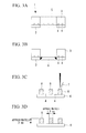
- the range of the removal portion 5 is appropriately determined depending on the position and the state of the damaged portion in the wall member with flow passages 1.
- a repairing base member 6 that is machined into a size of the removal portion 5 (see Fig. 3A ) is girth welded to the existing base member 2.
- a nickel-based superalloy with a thickness of 1.6 mm is used for the repairing base member 6.
- the product "Tomilloy” of Mitsubishi Materials Corporation, the product “Inconel 617”of Special Metals Corporation, and the product “hastelloy X” of Haynes International or the like are preferable for use as the repairing base member 6 and filler metal, for example.
- a plurality of overlay welds using powdered welding material 7 are applied on the repairing base member 6 that is girth welded on the existing base member 2 (see Fig. 3B).
- Fig. 3C is a partial enlarged view of the repairing base member 6.
- the flow passages 4 are formed between a plurality of overlay welded beads 8 formed by providing the plurality of the overlay welds onto the repairing base member 6.
- the overlay welding is performed by YAG laser welding (laser welding), for example.
- the beads 8 formed by the overlay welding are weaving beads (referred to as "beads", hereinafter).
- the beads 8 may be linear beads.
- Each of the beads 8 is formed to have a thickness of 3 mm and a weaving width of 2.5 mm, for example.
- the bead 8 is formed into a predetermined shape by the welding, and may be provided with a weld reinforcement having a height of approximately +1 mm taking account of a post treatment after the welding.
- the output of the YAG laser welding used for the overlay welding is preferably 350 W to 700 W. This is because a welding defect occurs if the laser output is 350 W or less, and thermal deformation or a welding crack occurs on the repairing base member 6 if the laser output is 700 W or more due to an excessive heat input.
- the welding speed is preferably 100 mm/min to 500 mm/min. This is because deformation or a welding crack occurs on the repairing base member 6 at the welding speed of 100 mm/min due to an excessive heat input, and welding residue occurs at the speed of 500 mm/min or more due to too rapid welding speed.
- a nickel-based superalloy that is the same as the repairing base member 6 or the product "Inconel 625" of Special Metals Corporation is preferably used for the powdered welding material 7.
- the powdered welding material to be used preferably has a particle diameter of 125 ⁇ m to 500 ⁇ m.
- the powder is supplied at the powder supply rate of 3 g/min to 15 g/min. It takes longer time to form the beads 8 at the powder supply rate of 3 g/min or less, and a welding defect occurs at the powder supply rate of 15 g/min or more due to excessive powder supply rate.
- the bead 8 is fabricated into a predetermined shape with a thickness of 2 mm and a width of 1.5 mm.
- the repairing plate member 9 with a thickness of 2 mm, for example is welded onto the surface of each of the plurality of the beads 8, for example.
- Piercing welding 12 is applied to the repairing plate member 9 and each of the beads 8 by using the YAG laser welding. The laser is so irradiated as to pierce the center of each bead 8.
- the following operation and effects can be attained.
- the overlay welds are provided onto the repairing base member 6 so as to form the plurality of the beads 8 thereon, and the repairing plate member 9 is welded by the YAG laser welding (laser welding) onto the surfaces of the overlay welded beads 8. Accordingly, it is possible to accomplish the repairing for the wall member with flow passages 1 having the flow passages 4 whose intervals are narrow. As a result, the repairing cost for the wall member with flow passages 1 can be reduced.
- the overlay welded beads 8 are formed by the YAG laser welding using powdered welding material 7. Therefore, it is possible to form the beads 8 each of which has a narrow and thin width. Accordingly, it is possible to create the flow passages 4 having narrow intervals therebetween on the repairing base member 6.
- each of the beads 8 formed by using the powdered welding material 7 has the weld reinforcement with the height of 2 mm and the width of 1.5 mm, but the present invention is not limited to this, and the bead 8 may have any height and width that can form the flow passages 4 of the wall member with flow passages 1 forming the tail pipe 50.
- Welding using an electron beam can be used instead of the YAG laser welding.
- the repairing base member 6 may have any thickness as far as it is appropriate for the wall member with flow passages 1 forming the tail pipe 50.
- the repairing method for the wall member with flow passages of the present embodiment is different from the first embodiment, where the repairing base member is provided with pipes before applying the overlay welding onto the repairing base member in the flow passage forming stage and the others are the same.
- same numbers refer to same components and same repairing methods for the wall member with flow passages, and descriptions thereof will be omitted.
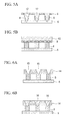
- Fig. 4A to Fig. 4C are drawings of explaining the repairing method for the wall member with flow passages according to the second embodiment of the present invention.
- a plurality of cooling pipes (pipes) 10 are disposed on the repairing base member 6 at equal intervals.
- Each of the cooling pipes 10 serves for forming a flow passage 11 in the same shape as that of the flow passage 4 formed in the wall member with flow passages 1 (see Fig. 2 ) forming the tail pipe 50 (see Fig. 1 ), and may have a height of 2 mm and a width of 1.5 mm, for example.
- the overlay welding is applied between the plurality of the cooling pipes 10 disposed on the repairing base member 6 at the equal intervals.
- the overlay welding is carried out by the YAG laser welding using powdered welding material.
- the beads 8 of the overlay welding are so formed at the approximately same height as that of the cooling pipes 10 as to fill the space between the cooling pipes 10.
- overlay welding 13 (referred to as “air-side-surface overlay welding”, hereinafter) is further applied onto the cooling pipes 10 and the surfaces of the overlay welded beads 8.
- the air-side-surface overlay welding 13 is so applied as to reach the same level of the surface of the existing wall member with flow passages 1 (see Fig. 2 ).
- the repairing method for the wall member with flow passages attains the following operation and effects.
- the plurality of the cooling pipes (pipes) 10 are provided on the repairing base member 6 and the overlay welding is applied between these cooling pipes 10. Therefore, the height of the overlay welded beads 8 can be set at the same height as that of the cooling pipes 10, and the width of the overlay welded beads 8 can be set at the same width as the interval between the adjacent cooling pipes 10. Accordingly, it is possible to reduce the time required for the overlay welding.
- the air-side-surface overlay welding (overlay welding) 13 is further applied onto the surfaces of the overlay welded beads 8. Therefore, the air-side-surface overlay welding 13 can be configured to have a desired thickness and shape. Accordingly, the air-side-surface overlay welding 13 can have the same shape as that of the existing wall member with flow passages 1 (see Fig. 2 ).
- the repairing method for the wall member with flow passages of the present embodiment is different from the first embodiment, where the overlay welding is applied to the opposite surface of the plate member in the plate member welding stage, and the others are the same.
- same numbers refer to same components and same repairing methods for the wall member with flow passages, and descriptions thereof will be omitted.
- Fig. 5A and Fig. 5B are drawings of explaining the repairing method for the wall member with flow passages according to the third embodiment of the present invention.
- the repairing plate member 9 with a thickness of 1 mm, for example is welded onto the surfaces of the plural formed beads 8.
- the piercing welding 12 by using the YAG laser welding is applied to the repairing plate member 9 and the each bead 8.
- the laser is so irradiated as to pierce the center of each bead 8.
- the air-side-surface overlay welding (overlay welding) 13 is applied onto the other surface opposite to the surface of the repairing plate member 9, which is in contact with the surfaces of the beads 8.
- the air-side-surface overlay welding 13 is performed by the YAG laser welding using powdered welding material.
- the air-side-surface overlay welding 13 is smoothly and evenly applied so as not to generate a difference in level from the plate member 3 of the existing wall member with flow passages 1 (see Fig. 2 ).
- the repairing method for the wall member with flow passages attains the following operation and effects.
- the air-side-surface overlay welding (overlay welding) 13 is further applied onto the other surface opposite to the surface of the repairing plate member 9, which is welded to the surfaces of each of the overlay welded beads 8. Therefore, the repairing plate member 9 to which the air-side-surface overlay welding 13 is applied can be configured to have a desired thickness and shape. Accordingly, the air-side-surface overlay welding 13 can have the same shape as that of the existing wall member with flow passages 1 (see Fig. 2 ).
- the repairing method for the wall member with flow passages of the present embodiment is different from the first embodiment, where the welding is applied to the plate member provided with a plurality of slits, and the others are the same.
- same numbers refer to same components and same repairing methods for the wall member with flow passages, and descriptions thereof will be omitted.
- Fig. 6A and Fig. 6B are drawings of explaining the repairing method for the wall member with flow passages according to the fourth embodiment of the present invention.
- a plurality of slits 15 are provided in the repairing plate member 14 with a thickness of 2 mm, for example.
- Each of the slits 15 provided in the repairing plate member 14 has a V-shaped cross sectional shape.
- the plurality of the slits 15 are so formed as to have the same intervals as those of the surfaces of the beads 8 on which the repairing plate member 14 is welded.
- the repairing plate member 14 having the plurality of the slits 15 is welded onto the surface of the beads 8.
- Slit welding 16 is applied to the repairing plate member 14 by using the laser welding. The laser is so irradiated with adding the filler metal as to pierce the center of each slit 15 formed in the repairing plate member 14 and the center of each bead 8.
- the repairing method for the wall member with flow passages attains the following operation and effects.
- the slits 15 are provided in the repairing plate member 14. Therefore, when the slit welding (welding) 16 is so applied to the repairing plate member 14 as to be welded onto the surfaces of the overlay welded beads 8, welding positions can be confirmed visually. Accordingly, it is possible to prevent the welding from failing.
- the repairing plate member 14 and each bead 8 are welded by the slit welding 16 using the laser, but the present invention is not limited to this, and the slit welding 16 may be performed by TIG welding, plasma welding, or electron beam welding.
Landscapes
- Engineering & Computer Science (AREA)
- Mechanical Engineering (AREA)
- Physics & Mathematics (AREA)
- Optics & Photonics (AREA)
- Plasma & Fusion (AREA)
- General Engineering & Computer Science (AREA)
- Chemical & Material Sciences (AREA)
- Combustion & Propulsion (AREA)
- Laser Beam Processing (AREA)
- Welding Or Cutting Using Electron Beams (AREA)
- Butt Welding And Welding Of Specific Article (AREA)
Abstract

Description
- The present invention relates to a method for partially repairing a wall member with flow passages for use in a combustor of a gas turbine, for example.
- In a conventional repairing method for repairing a damaged portion of a combustor of a gas turbine, a whole member or a part on which a damage is generated is replaced (For example, Patent Literature 1).
Patent Literature 2 discloses a repairing method for a case in which a crack occurs on a plate having flow passages (referred to as "cooling channels", hereinafter) inside a combustor or the like. -
- {PTL 1}
The Publication of Japanese Patent No.3915423 - {PTL 2}
Japanese Unexamined Patent Application, Publication No.2002-361523 - However, in a repairing method for the case in which a damage is generated on a tail pipe of a combustor having cooling channels, a damaged portion thereof is removed and part of a base member forming a gas path of the tail pipe is girth welded to the removed portion, and flow passages serving as the cooling channels are formed on the base member by use of a grinder. Thereafter, a repair is made by inserting copper wires into the formed flow passages and welding top portions of the copper wires, and then pulling the copper wires out of the flow passages so as to form the cooling channels. In the case of repairing a tail pipe of a combustor having narrow intervals between cooling channels for the sake of enhancing the cooling effect, the cooling channels cannot be formed by a grinder, so that each panel included in the tail pipe is required to be replaced, which causes a problem of increase in time and cost for the repairing work.
The invention described inPatent Literature 2 has a problem of increase in time and cost for the repairing work if a crack occurs in a wide range. - The present invention has been made in the light of the above circumstances, and has an object to provide a repairing method capable of reducing time and cost required for a partial repairing work on a wall member with flow passages.
- In order to solve the above problems, the repairing method for a wall member with flow passages of the present invention employs the following solutions.
A repairing method for a wall member with flow passages according to one aspect of the present invention includes a removal stage of removing a portion of the wall member provided with a plurality of flow passages between a base member and a plate member; a base member welding stage of welding a repairing base member to the portion removed in the removal stage; a flow passage forming stage of providing a plurality of overlay welds on the repairing base member and forming flow passages between the overlay welds, and a plate member welding stage of welding a repairing plate member onto surfaces of the plurality of the overlay welds. - Conventionally, if a part of a wall member with a plurality of flow passages between a base member and a plate member is removed, a repairing base member is girth welded with the part removed, and flow passages are formed on the repairing base member by use of a grinder. However, if the flow passages to be formed on the repairing base member have narrow intervals therebetween, it is difficult to form such flow passages by use of a grinder.
In the one aspect of the present invention, plural overlay welds are provided onto the repairing base member, and the repairing plate member is welded onto the surfaces of the overlay welds. Therefore, it is possible to repair even the wall member with flow passages having narrow intervals therebetween. Accordingly, the repairing cost for the wall member with flow passages can be reduced. - In the repairing method for a wall member with flow passages according to the one aspect of the present invention, overlay welding includes laser welding or electron beam welding using powdered welding material.
- Overlay welding is performed by laser welding or electron beam welding using powdered welding material. Therefore, it is possible to perform welding to provide a narrow and thin weld width. Accordingly, it is possible to create the flow passages having narrow intervals on the repairing base member.
- In the repairing method for a wall member with flow passages according to the one aspect of the present invention, in the flow passage forming stage, a plurality of pipes are provided on the repairing base member before the plural overlay welds are provided on the repairing base member, and the overlay welding is applied between the plurality of the pipes.
- The plurality of the pipes are provided on the repairing base member and the overlay welding is applied between these pipes. Therefore, the height of the overlay welds can be set at the same height as that of the pipes, and the width of the overlay welds can be set at the same width as the interval between the pipes. Accordingly, it is possible to reduce the time required for the overlay welding.
- In the repairing method for a wall member with flow passages according to the one aspect of the present invention, overlay welding is further applied onto surfaces of the plurality of the overlay welds or a surface opposite to a surface of the repairing plate member that is welded to the plurality of the overlay welds.
- Overlay welding is further applied onto surfaces of the overlay welds or a surface opposite to a surface of the repairing plate member that is welded to the surfaces of the overlay welds. Therefore, the overlay welds or the overlay welded repairing plate member can be configured to have a desired thickness and shape. Accordingly, the overlay welds or the overlay welded repairing plate member can have the same shape as that of the existing wall member with flow passages.
- In the repairing method for a wall member with flow passages according to the one aspect of the present invention, a plurality of slits are provided in the repairing plate member.
- The slits are provided in the repairing plate member. Therefore, when the repairing plate member is welded onto the surfaces of the overlay welds, welding positions can be confirmed visually. Accordingly, it is possible to prevent the welding from failing.
In the above described method, the welding may be performed by welding using an electron beam instead of using a laser. In this case, the combustor is disposed in a vacuum chamber, where the repairing work is carried out. - The plurality of the overlay welds are provided on the repairing base member, and the repairing plate member is welded onto the surfaces of the overlay welds. Therefore, it is possible to repair the wall member with flow passages with narrow intervals therebetween. Accordingly, the repairing cost for the wall member with flow passages can be reduced.
-
- {
Fig. 1 }
Fig. 1 is a longitudinal section view of a conventional combustor of a gas turbine. - {
Fig. 2 }
Fig. 2 is a partial cross sectional view of a wall member with flow passages forming a tail pipe of the combustor illustrated inFig. 1 . - {
Fig. 3A }
Fig. 3A is a drawing of explaining a repairing method for a wall member with flow passages according to the first embodiment of the present invention. - {
Fig. 3B }
Fig. 3B is a drawing of explaining the repairing method for the wall member with flow passages according to the first embodiment of the present invention. - {
Fig. 3C }
Fig. 3C is a drawing of explaining the repairing method for the wall member with flow passages according to the first embodiment of the present invention. - {
Fig. 3D }
Fig. 3D is a drawing of explaining the repairing method for the wall member with flow passages according to the first embodiment of the present invention. - {
Fig. 3E }
Fig. 3E is a drawing of explaining the repairing method for the wall member with flow passages according to the first embodiment of the present invention. - {
Fig. 4A }
Fig. 4A is a drawing of explaining a repairing method for a wall member with flow passages according to the second embodiment of the present invention. - {
Fig. 4B }
Fig. 4B is a drawing of explaining the repairing method for the wall member with flow passages according to the second embodiment of the present invention. - {
Fig. 4C }
Fig. 4C is a drawing of explaining the repairing method for the wall member with flow passages according to the second embodiment of the present invention. - {
Fig. 5A }
Fig. 5A is a drawing of explaining a repairing method for a wall member with flow passages according to the third embodiment of the present invention. - {
Fig. 5B }
Fig. 5B is a drawing of explaining the repairing method for the wall member with flow passages according to the third embodiment of the present invention. - {
Fig. 6A }
Fig. 6A is a drawing of explaining a repairing method for a wall member with flow passages according to the fourth embodiment of the present invention. - {
Fig. 6B }
Fig. 6B is a drawing of explaining the repairing method for the wall member with flow passages according to the fourth embodiment of the present invention. -
Fig. 1 illustrates atail pipe 50 of a combustor of a gas turbine. In the present embodiment and the following various embodiments, descriptions will be provided on a repairing method for a wall member with flow passages of thetail pipe 50 of the combustor (not illustrated), but the present invention is not limited to this, and is applicable to a repairing for a wall member with plural flow passages (not illustrated) between a base member (not illustrated) and a plate member (not illustrated).
The wall member with flow passages forming thetail pipe 50 includes the base member (not illustrated) forming the gas path of the combustor and the plate member (not illustrated) on which a plurality of flow passages that are cooling channels are formed. -
Fig. 2 is a partial sectional view of the wall member with flow passages that form the tail pipe.
The wall member with flow passages 1 forming the tail pipe 50 (seeFig. 1 ) of the combustor of the gas turbine (not illustrated) includes thebase member 2 and theplate member 3 on which the plurality of theflow passages 4 are formed. Thebase member 2 and theplate member 3 are bonded together by brazing. This bonding by brazing creates a plurality offlow passages 4 between thebase member 2 and theplate member 3.
In the repairing method for the wall member with flow passages 1 according to the present embodiment, a repair is carried out on aportion 5 of the wall member with flow passages 1 including a damaged portion (not illustrated) generated on theplate member 3 of the wall member with flow passages 1 (referred to as a "removal portion", hereinafter). The repairing method for the wall member with flow passages 1 includes a removal stage, a base member welding stage, a flow passage forming stage and a plate member welding stage. - As illustrated in
Fig. 3A , in the removal stage, theremoval portion 5 including the damaged portion is removed from the wall member with flow passages 1 forming thetail pipe 50 of the combustor (seeFig. 1 ). The range of theremoval portion 5 is appropriately determined depending on the position and the state of the damaged portion in the wall member with flow passages 1. - As illustrated in
Fig. 3B , in the base member welding stage, a repairingbase member 6 that is machined into a size of the removal portion 5 (seeFig. 3A ) is girth welded to the existingbase member 2.
A nickel-based superalloy with a thickness of 1.6 mm is used for the repairingbase member 6. The product "Tomilloy" of Mitsubishi Materials Corporation, the product "Inconel 617"of Special Metals Corporation, and the product "hastelloy X" of Haynes International or the like are preferable for use as the repairingbase member 6 and filler metal, for example. - As illustrated in
Fig. 3C , in the flow passage forming stage, a plurality of overlay welds usingpowdered welding material 7 are applied on the repairingbase member 6 that is girth welded on the existing base member 2 (seeFig. 3B). Fig. 3C is a partial enlarged view of the repairingbase member 6. Theflow passages 4 are formed between a plurality of overlay weldedbeads 8 formed by providing the plurality of the overlay welds onto the repairingbase member 6. - The overlay welding is performed by YAG laser welding (laser welding), for example. The
beads 8 formed by the overlay welding are weaving beads (referred to as "beads", hereinafter). Thebeads 8 may be linear beads. Each of thebeads 8 is formed to have a thickness of 3 mm and a weaving width of 2.5 mm, for example. Thebead 8 is formed into a predetermined shape by the welding, and may be provided with a weld reinforcement having a height of approximately +1 mm taking account of a post treatment after the welding. - The output of the YAG laser welding used for the overlay welding is preferably 350 W to 700 W. This is because a welding defect occurs if the laser output is 350 W or less, and thermal deformation or a welding crack occurs on the repairing
base member 6 if the laser output is 700 W or more due to an excessive heat input.
The welding speed is preferably 100 mm/min to 500 mm/min. This is because deformation or a welding crack occurs on the repairingbase member 6 at the welding speed of 100 mm/min due to an excessive heat input, and welding residue occurs at the speed of 500 mm/min or more due to too rapid welding speed. - A nickel-based superalloy that is the same as the repairing
base member 6 or the product "Inconel 625" of Special Metals Corporation is preferably used for thepowdered welding material 7. The powdered welding material to be used preferably has a particle diameter of 125 µm to 500 µm. The powder is supplied at the powder supply rate of 3 g/min to 15 g/min. It takes longer time to form thebeads 8 at the powder supply rate of 3 g/min or less, and a welding defect occurs at the powder supply rate of 15 g/min or more due to excessive powder supply rate. - As illustrated in
Fig. 3D , if the weld reinforcement is provided for eachbead 8, thebead 8 is fabricated into a predetermined shape with a thickness of 2 mm and a width of 1.5 mm. - As illustrated in
Fig. 3E , in the plate member welding stage, the repairingplate member 9 with a thickness of 2 mm, for example, is welded onto the surface of each of the plurality of thebeads 8, for example. Piercingwelding 12 is applied to the repairingplate member 9 and each of thebeads 8 by using the YAG laser welding. The laser is so irradiated as to pierce the center of eachbead 8. - As described above, according to the repairing method for the wall member with flow passages of the present embodiment, the following operation and effects can be attained.
The overlay welds are provided onto the repairingbase member 6 so as to form the plurality of thebeads 8 thereon, and the repairingplate member 9 is welded by the YAG laser welding (laser welding) onto the surfaces of the overlay weldedbeads 8. Accordingly, it is possible to accomplish the repairing for the wall member with flow passages 1 having theflow passages 4 whose intervals are narrow. As a result, the repairing cost for the wall member with flow passages 1 can be reduced. - The overlay welded
beads 8 are formed by the YAG laser welding usingpowdered welding material 7. Therefore, it is possible to form thebeads 8 each of which has a narrow and thin width. Accordingly, it is possible to create theflow passages 4 having narrow intervals therebetween on the repairingbase member 6. - In the present embodiment, it has been described that each of the
beads 8 formed by using thepowdered welding material 7 has the weld reinforcement with the height of 2 mm and the width of 1.5 mm, but the present invention is not limited to this, and thebead 8 may have any height and width that can form theflow passages 4 of the wall member with flow passages 1 forming thetail pipe 50.
Welding using an electron beam can be used instead of the YAG laser welding.
The repairingbase member 6 may have any thickness as far as it is appropriate for the wall member with flow passages 1 forming thetail pipe 50. - Hereinafter, descriptions will be provided on the second embodiment of the present invention. The repairing method for the wall member with flow passages of the present embodiment is different from the first embodiment, where the repairing base member is provided with pipes before applying the overlay welding onto the repairing base member in the flow passage forming stage and the others are the same. Thus, same numbers refer to same components and same repairing methods for the wall member with flow passages, and descriptions thereof will be omitted.
-
Fig. 4A to Fig. 4C are drawings of explaining the repairing method for the wall member with flow passages according to the second embodiment of the present invention.
As illustrated inFig. 4A , in the flow passage forming stage, a plurality of cooling pipes (pipes) 10 are disposed on the repairingbase member 6 at equal intervals. Each of the coolingpipes 10 serves for forming aflow passage 11 in the same shape as that of theflow passage 4 formed in the wall member with flow passages 1 (seeFig. 2 ) forming the tail pipe 50 (seeFig. 1 ), and may have a height of 2 mm and a width of 1.5 mm, for example. - As illustrated in
Fig. 4B , the overlay welding is applied between the plurality of the coolingpipes 10 disposed on the repairingbase member 6 at the equal intervals. The overlay welding is carried out by the YAG laser welding using powdered welding material. Thebeads 8 of the overlay welding are so formed at the approximately same height as that of the coolingpipes 10 as to fill the space between the coolingpipes 10. - As illustrated in
Fig. 4C , in the plate member welding stage, overlay welding 13 (referred to as "air-side-surface overlay welding", hereinafter) is further applied onto the coolingpipes 10 and the surfaces of the overlay weldedbeads 8. The air-side-surface overlay welding 13 is so applied as to reach the same level of the surface of the existing wall member with flow passages 1 (seeFig. 2 ). - As described above, the repairing method for the wall member with flow passages according to the present embodiment attains the following operation and effects.
The plurality of the cooling pipes (pipes) 10 are provided on the repairingbase member 6 and the overlay welding is applied between these coolingpipes 10. Therefore, the height of the overlay weldedbeads 8 can be set at the same height as that of the coolingpipes 10, and the width of the overlay weldedbeads 8 can be set at the same width as the interval between theadjacent cooling pipes 10. Accordingly, it is possible to reduce the time required for the overlay welding. - The air-side-surface overlay welding (overlay welding) 13 is further applied onto the surfaces of the overlay welded
beads 8. Therefore, the air-side-surface overlay welding 13 can be configured to have a desired thickness and shape. Accordingly, the air-side-surface overlay welding 13 can have the same shape as that of the existing wall member with flow passages 1 (seeFig. 2 ). - Hereinafter, the third embodiment of the present invention will be described. The repairing method for the wall member with flow passages of the present embodiment is different from the first embodiment, where the overlay welding is applied to the opposite surface of the plate member in the plate member welding stage, and the others are the same. Thus, same numbers refer to same components and same repairing methods for the wall member with flow passages, and descriptions thereof will be omitted.
-
Fig. 5A and Fig. 5B are drawings of explaining the repairing method for the wall member with flow passages according to the third embodiment of the present invention.
As illustrated inFig. 5A , in the plate member welding stage, the repairingplate member 9 with a thickness of 1 mm, for example, is welded onto the surfaces of the plural formedbeads 8. The piercingwelding 12 by using the YAG laser welding is applied to the repairingplate member 9 and the eachbead 8. The laser is so irradiated as to pierce the center of eachbead 8. - As illustrated in
Fig. 5B , the air-side-surface overlay welding (overlay welding) 13 is applied onto the other surface opposite to the surface of the repairingplate member 9, which is in contact with the surfaces of thebeads 8. The air-side-surface overlay welding 13 is performed by the YAG laser welding using powdered welding material. The air-side-surface overlay welding 13 is smoothly and evenly applied so as not to generate a difference in level from theplate member 3 of the existing wall member with flow passages 1 (seeFig. 2 ). - As described above, the repairing method for the wall member with flow passages according to the present embodiment attains the following operation and effects.
The air-side-surface overlay welding (overlay welding) 13 is further applied onto the other surface opposite to the surface of the repairingplate member 9, which is welded to the surfaces of each of the overlay weldedbeads 8. Therefore, the repairingplate member 9 to which the air-side-surface overlay welding 13 is applied can be configured to have a desired thickness and shape. Accordingly, the air-side-surface overlay welding 13 can have the same shape as that of the existing wall member with flow passages 1 (seeFig. 2 ). - Hereinafter, the fourth embodiment of the present invention will be described. The repairing method for the wall member with flow passages of the present embodiment is different from the first embodiment, where the welding is applied to the plate member provided with a plurality of slits, and the others are the same. Thus, same numbers refer to same components and same repairing methods for the wall member with flow passages, and descriptions thereof will be omitted.
-
Fig. 6A and Fig. 6B are drawings of explaining the repairing method for the wall member with flow passages according to the fourth embodiment of the present invention.
As illustrated inFig. 6A , in the plate member welding stage, a plurality ofslits 15 are provided in the repairingplate member 14 with a thickness of 2 mm, for example. Each of theslits 15 provided in the repairingplate member 14 has a V-shaped cross sectional shape. The plurality of theslits 15 are so formed as to have the same intervals as those of the surfaces of thebeads 8 on which the repairingplate member 14 is welded. - As illustrated in
Fig. 6B , in the plate member welding stage, the repairingplate member 14 having the plurality of theslits 15 is welded onto the surface of thebeads 8.Slit welding 16 is applied to the repairingplate member 14 by using the laser welding. The laser is so irradiated with adding the filler metal as to pierce the center of each slit 15 formed in the repairingplate member 14 and the center of eachbead 8. - As described above, the repairing method for the wall member with flow passages according to the present embodiment attains the following operation and effects.
Theslits 15 are provided in the repairingplate member 14. Therefore, when the slit welding (welding) 16 is so applied to the repairingplate member 14 as to be welded onto the surfaces of the overlay weldedbeads 8, welding positions can be confirmed visually. Accordingly, it is possible to prevent the welding from failing. - In the description of the present embodiment, the repairing
plate member 14 and eachbead 8 are welded by the slit welding 16 using the laser, but the present invention is not limited to this, and the slit welding 16 may be performed by TIG welding, plasma welding, or electron beam welding. -
- 1
- Wall member with flow passages
- 2
- Base member
- 3
- Plate member
- 4
- Flow passage
- 6
- Repairing base member
- 8
- Bead
- 9
- Repairing plate member
Claims (5)
- A repairing method for a wall member with flow passages comprising:a removal stage of removing a portion of the wall member provided with a plurality of flow passages between a base member and a plate member;a base member welding stage of welding a repairing base member to the portion removed in the removal stage;a flow passage forming stage of providing a plurality of overlay welds on the repairing base member and forming flow passages between the overlay welds; anda plate member welding stage of welding a repairing plate member onto surfaces of the plurality of the overlay welds.
- The repairing method for a wall member with flow passages according to claim 1, wherein
the overlay welding includes laser welding or electron beam welding using powdered welding material. - The repairing method for a wall member with flow passages according to claim 1 or claim 2, wherein
in the flow passage forming stage, a plurality of pipes are provided on the repairing base member before the plurality of the overlay welds are provided on the repairing base member, and the overlay welding is applied between the plurality of the pipes. - The repairing method for a wall member with flow passages according to any one of claim 1 to claim 3, wherein
overlay welding is further applied onto surfaces of the plurality of the overlay welds or a surface opposite to a surface of the repairing plate member that is welded to the plurality of the overlay welds. - The repairing method for a wall member with flow passages according to any one of claim 1 to claim 4, wherein
a plurality of slits are provided in the repairing plate member.
Applications Claiming Priority (2)
| Application Number | Priority Date | Filing Date | Title |
|---|---|---|---|
| JP2010009990A JP5578864B2 (en) | 2010-01-20 | 2010-01-20 | Repair method of wall member with flow path |
| PCT/JP2011/050390 WO2011089957A1 (en) | 2010-01-20 | 2011-01-13 | Method for repairing wall member with passage |
Publications (3)
| Publication Number | Publication Date |
|---|---|
| EP2527077A1 true EP2527077A1 (en) | 2012-11-28 |
| EP2527077A4 EP2527077A4 (en) | 2013-06-19 |
| EP2527077B1 EP2527077B1 (en) | 2015-03-18 |
Family
ID=44306759
Family Applications (1)
| Application Number | Title | Priority Date | Filing Date |
|---|---|---|---|
| EP11734564.5A Active EP2527077B1 (en) | 2010-01-20 | 2011-01-13 | Repairing method for wall member with flow passages |
Country Status (6)
| Country | Link |
|---|---|
| US (1) | US9199342B2 (en) |
| EP (1) | EP2527077B1 (en) |
| JP (1) | JP5578864B2 (en) |
| KR (1) | KR101306498B1 (en) |
| CN (1) | CN102630193B (en) |
| WO (1) | WO2011089957A1 (en) |
Cited By (1)
| Publication number | Priority date | Publication date | Assignee | Title |
|---|---|---|---|---|
| NO20162002A1 (en) * | 2016-12-15 | 2018-06-18 | Turbine Power Sl | Method of repairing crack damage in steel structures |
Families Citing this family (21)
| Publication number | Priority date | Publication date | Assignee | Title |
|---|---|---|---|---|
| US10314594B2 (en) | 2012-12-14 | 2019-06-11 | Corquest Medical, Inc. | Assembly and method for left atrial appendage occlusion |
| US10307167B2 (en) | 2012-12-14 | 2019-06-04 | Corquest Medical, Inc. | Assembly and method for left atrial appendage occlusion |
| US10813630B2 (en) | 2011-08-09 | 2020-10-27 | Corquest Medical, Inc. | Closure system for atrial wall |
| JP5456124B2 (en) * | 2012-07-04 | 2014-03-26 | 三菱重工業株式会社 | Method of welding erosion resistant metal material and turbine blade |
| CN104718348B (en) * | 2012-09-21 | 2016-09-28 | 三菱日立电力系统株式会社 | Welding method of corrosion-resistant metal material and turbine blade |
| US20140142689A1 (en) | 2012-11-21 | 2014-05-22 | Didier De Canniere | Device and method of treating heart valve malfunction |
| US20160032766A1 (en) * | 2013-03-14 | 2016-02-04 | General Electric Company | Components with micro cooled laser deposited material layer and methods of manufacture |
| US9366139B2 (en) | 2013-04-09 | 2016-06-14 | Mitsubishi Heavy Industries, Ltd. | Repair method of plate member, plate member, combustor, ring segment, and gas turbine |
| CN105143639B (en) * | 2013-04-09 | 2017-04-26 | 三菱重工业株式会社 | Method for repairing plate-shaped member, plate-shaped member, combustor, split ring, and gas turbine |
| JP6043704B2 (en) * | 2013-09-19 | 2016-12-14 | 東京瓦斯株式会社 | Motor cooler and method for manufacturing motor cooler |
| JP2015069165A (en) | 2013-09-30 | 2015-04-13 | ブラザー工業株式会社 | Developing device, blade unit, and method of manufacturing developing device |
| US9377711B2 (en) * | 2013-09-30 | 2016-06-28 | Brother Kogyo Kabushiki Kaisha | Developing device, blade unit, and developing device manufacturing method |
| JP2015069166A (en) | 2013-09-30 | 2015-04-13 | ブラザー工業株式会社 | Developing device, blade unit, and manufacturing method of developing device |
| US9126279B2 (en) * | 2013-09-30 | 2015-09-08 | General Electric Company | Brazing method |
| US9566443B2 (en) | 2013-11-26 | 2017-02-14 | Corquest Medical, Inc. | System for treating heart valve malfunction including mitral regurgitation |
| CN110270759B (en) | 2014-01-08 | 2021-05-14 | 松下知识产权经营株式会社 | Laser welding method |
| JP6221906B2 (en) | 2014-03-31 | 2017-11-01 | ブラザー工業株式会社 | Developing device and manufacturing method of developing device |
| US10842626B2 (en) | 2014-12-09 | 2020-11-24 | Didier De Canniere | Intracardiac device to correct mitral regurgitation |
| CN109108568A (en) * | 2018-09-12 | 2019-01-01 | 新疆科鼎环保科技有限公司 | High pressure valve leakage position restorative procedure |
| US11517969B2 (en) * | 2019-01-24 | 2022-12-06 | General Electric Company | Weld-brazing techniques |
| JP6892542B1 (en) * | 2020-08-19 | 2021-06-23 | 株式会社神戸製鋼所 | Manufacturing method of modeled object and modeled object |
Family Cites Families (11)
| Publication number | Priority date | Publication date | Assignee | Title |
|---|---|---|---|---|
| JPS6192721A (en) * | 1984-10-15 | 1986-05-10 | Mitsubishi Heavy Ind Ltd | Production of cooling panel |
| WO1995032831A1 (en) * | 1994-05-26 | 1995-12-07 | Bgm (Patents) Limited | Work piece repair |
| US5933699A (en) * | 1996-06-24 | 1999-08-03 | General Electric Company | Method of making double-walled turbine components from pre-consolidated assemblies |
| JP4110632B2 (en) | 1998-09-30 | 2008-07-02 | 松下電器産業株式会社 | Sealed battery |
| US6427327B1 (en) * | 2000-11-29 | 2002-08-06 | General Electric Company | Method of modifying cooled turbine components |
| JP3915423B2 (en) | 2001-03-29 | 2007-05-16 | 株式会社日立製作所 | Gas turbine combustor liner structure and repair method |
| JP3581672B2 (en) | 2001-06-11 | 2004-10-27 | 三菱重工業株式会社 | Method for repairing plate-like body having flow path inside |
| US7216485B2 (en) | 2004-09-03 | 2007-05-15 | General Electric Company | Adjusting airflow in turbine component by depositing overlay metallic coating |
| JP2006208227A (en) * | 2005-01-28 | 2006-08-10 | Babcock Hitachi Kk | Repair method of nozzle of reactor pressure vessel |
| JP4936718B2 (en) | 2005-12-12 | 2012-05-23 | ミヤチテクノス株式会社 | Laser welding method |
| JP5260402B2 (en) * | 2009-04-30 | 2013-08-14 | 三菱重工業株式会社 | Plate-like body manufacturing method, plate-like body, gas turbine combustor, and gas turbine |
-
2010
- 2010-01-20 JP JP2010009990A patent/JP5578864B2/en active Active
-
2011
- 2011-01-13 CN CN201180004718.2A patent/CN102630193B/en active Active
- 2011-01-13 US US13/511,498 patent/US9199342B2/en active Active
- 2011-01-13 EP EP11734564.5A patent/EP2527077B1/en active Active
- 2011-01-13 WO PCT/JP2011/050390 patent/WO2011089957A1/en not_active Ceased
- 2011-01-13 KR KR1020127013052A patent/KR101306498B1/en active Active
Cited By (2)
| Publication number | Priority date | Publication date | Assignee | Title |
|---|---|---|---|---|
| NO20162002A1 (en) * | 2016-12-15 | 2018-06-18 | Turbine Power Sl | Method of repairing crack damage in steel structures |
| NO344485B1 (en) * | 2016-12-15 | 2020-01-13 | Turbine Power Sl | Method for repairing crack damage in steel structures |
Also Published As
| Publication number | Publication date |
|---|---|
| WO2011089957A1 (en) | 2011-07-28 |
| CN102630193B (en) | 2015-02-04 |
| CN102630193A (en) | 2012-08-08 |
| JP5578864B2 (en) | 2014-08-27 |
| KR101306498B1 (en) | 2013-09-09 |
| EP2527077A4 (en) | 2013-06-19 |
| EP2527077B1 (en) | 2015-03-18 |
| JP2011147952A (en) | 2011-08-04 |
| US9199342B2 (en) | 2015-12-01 |
| US20120272611A1 (en) | 2012-11-01 |
| KR20120083494A (en) | 2012-07-25 |
Similar Documents
| Publication | Publication Date | Title |
|---|---|---|
| US9199342B2 (en) | Repairing method for wall member with flow passages | |
| JP5008354B2 (en) | Method for repairing a blade of an integrated bladed disk of a turbomachine and a test piece for carrying out the method | |
| JP5322371B2 (en) | How to repair a disk with an integrated blade, test piece at the start and end of work | |
| US10450871B2 (en) | Repair of dual walled metallic components using directed energy deposition material addition | |
| US8156649B2 (en) | Gas turbine hot gas component repair method | |
| CN1572406A (en) | Process for repairing turbine components | |
| JP2008110404A (en) | Method and apparatus for repairing aperture and adjacent defect in flange | |
| CN102000915A (en) | Combustion cap effusion plate laser weld repair | |
| JP6581498B2 (en) | Turbine rotor disk repair method | |
| JP5535799B2 (en) | Repair method of metal parts and repaired metal parts | |
| JP2014534079A (en) | Method of joining or repairing superalloy structures using resistance brazing of convex parts and corresponding superalloy components | |
| EP2239083A1 (en) | Internally supported airfoil and method for internally supporting a hollow airfoil during manufacturing. | |
| JP6370557B2 (en) | Overlay welding method | |
| JP5959849B2 (en) | Laser overlay welding method | |
| EP2644310A1 (en) | A method of joining at least two components, a method for rendering a component resistant to erosion, and a turbine blade | |
| US20210129268A1 (en) | Laser metal deposition with cored filler wire | |
| CN111872628A (en) | Method of repairing superalloy components using phase coalescence | |
| US12042875B2 (en) | Weld-brazing techniques | |
| JP2022517631A5 (en) | ||
| JP2024115122A (en) | How to repair a stationary blade | |
| JP2012098120A (en) | Method for repairing reactor core internal structure of nuclear reactor |
Legal Events
| Date | Code | Title | Description |
|---|---|---|---|
| PUAI | Public reference made under article 153(3) epc to a published international application that has entered the european phase |
Free format text: ORIGINAL CODE: 0009012 |
|
| 17P | Request for examination filed |
Effective date: 20120521 |
|
| AK | Designated contracting states |
Kind code of ref document: A1 Designated state(s): AL AT BE BG CH CY CZ DE DK EE ES FI FR GB GR HR HU IE IS IT LI LT LU LV MC MK MT NL NO PL PT RO RS SE SI SK SM TR |
|
| DAX | Request for extension of the european patent (deleted) | ||
| A4 | Supplementary search report drawn up and despatched |
Effective date: 20130521 |
|
| RIC1 | Information provided on ipc code assigned before grant |
Ipc: B23K 9/04 20060101ALI20130514BHEP Ipc: B23K 26/20 20060101ALI20130514BHEP Ipc: B23P 6/04 20060101ALI20130514BHEP Ipc: B23K 31/00 20060101AFI20130514BHEP Ipc: F02C 7/00 20060101ALI20130514BHEP Ipc: B23K 26/34 20060101ALI20130514BHEP Ipc: F01D 25/00 20060101ALI20130514BHEP Ipc: B23K 9/00 20060101ALI20130514BHEP Ipc: B23K 15/00 20060101ALI20130514BHEP |
|
| GRAP | Despatch of communication of intention to grant a patent |
Free format text: ORIGINAL CODE: EPIDOSNIGR1 |
|
| INTG | Intention to grant announced |
Effective date: 20141014 |
|
| GRAS | Grant fee paid |
Free format text: ORIGINAL CODE: EPIDOSNIGR3 |
|
| GRAA | (expected) grant |
Free format text: ORIGINAL CODE: 0009210 |
|
| AK | Designated contracting states |
Kind code of ref document: B1 Designated state(s): AL AT BE BG CH CY CZ DE DK EE ES FI FR GB GR HR HU IE IS IT LI LT LU LV MC MK MT NL NO PL PT RO RS SE SI SK SM TR |
|
| RAP1 | Party data changed (applicant data changed or rights of an application transferred) |
Owner name: MITSUBISHI HITACHI POWER SYSTEMS, LTD. |
|
| REG | Reference to a national code |
Ref country code: GB Ref legal event code: FG4D |
|
| REG | Reference to a national code |
Ref country code: CH Ref legal event code: EP |
|
| REG | Reference to a national code |
Ref country code: IE Ref legal event code: FG4D |
|
| RAP2 | Party data changed (patent owner data changed or rights of a patent transferred) |
Owner name: MITSUBISHI HITACHI POWER SYSTEMS, LTD. |
|
| REG | Reference to a national code |
Ref country code: AT Ref legal event code: REF Ref document number: 716228 Country of ref document: AT Kind code of ref document: T Effective date: 20150415 |
|
| REG | Reference to a national code |
Ref country code: DE Ref legal event code: R096 Ref document number: 602011014824 Country of ref document: DE Effective date: 20150430 |
|
| REG | Reference to a national code |
Ref country code: NL Ref legal event code: VDEP Effective date: 20150318 |
|
| REG | Reference to a national code |
Ref country code: NL Ref legal event code: VDEP Effective date: 20150318 |
|
| PG25 | Lapsed in a contracting state [announced via postgrant information from national office to epo] |
Ref country code: FI Free format text: LAPSE BECAUSE OF FAILURE TO SUBMIT A TRANSLATION OF THE DESCRIPTION OR TO PAY THE FEE WITHIN THE PRESCRIBED TIME-LIMIT Effective date: 20150318 Ref country code: LT Free format text: LAPSE BECAUSE OF FAILURE TO SUBMIT A TRANSLATION OF THE DESCRIPTION OR TO PAY THE FEE WITHIN THE PRESCRIBED TIME-LIMIT Effective date: 20150318 Ref country code: HR Free format text: LAPSE BECAUSE OF FAILURE TO SUBMIT A TRANSLATION OF THE DESCRIPTION OR TO PAY THE FEE WITHIN THE PRESCRIBED TIME-LIMIT Effective date: 20150318 Ref country code: NO Free format text: LAPSE BECAUSE OF FAILURE TO SUBMIT A TRANSLATION OF THE DESCRIPTION OR TO PAY THE FEE WITHIN THE PRESCRIBED TIME-LIMIT Effective date: 20150618 Ref country code: SE Free format text: LAPSE BECAUSE OF FAILURE TO SUBMIT A TRANSLATION OF THE DESCRIPTION OR TO PAY THE FEE WITHIN THE PRESCRIBED TIME-LIMIT Effective date: 20150318 |
|
| REG | Reference to a national code |
Ref country code: AT Ref legal event code: MK05 Ref document number: 716228 Country of ref document: AT Kind code of ref document: T Effective date: 20150318 |
|
| REG | Reference to a national code |
Ref country code: LT Ref legal event code: MG4D |
|
| PG25 | Lapsed in a contracting state [announced via postgrant information from national office to epo] |
Ref country code: RS Free format text: LAPSE BECAUSE OF FAILURE TO SUBMIT A TRANSLATION OF THE DESCRIPTION OR TO PAY THE FEE WITHIN THE PRESCRIBED TIME-LIMIT Effective date: 20150318 Ref country code: LV Free format text: LAPSE BECAUSE OF FAILURE TO SUBMIT A TRANSLATION OF THE DESCRIPTION OR TO PAY THE FEE WITHIN THE PRESCRIBED TIME-LIMIT Effective date: 20150318 Ref country code: GR Free format text: LAPSE BECAUSE OF FAILURE TO SUBMIT A TRANSLATION OF THE DESCRIPTION OR TO PAY THE FEE WITHIN THE PRESCRIBED TIME-LIMIT Effective date: 20150619 |
|
| PG25 | Lapsed in a contracting state [announced via postgrant information from national office to epo] |
Ref country code: NL Free format text: LAPSE BECAUSE OF FAILURE TO SUBMIT A TRANSLATION OF THE DESCRIPTION OR TO PAY THE FEE WITHIN THE PRESCRIBED TIME-LIMIT Effective date: 20150318 |
|
| PG25 | Lapsed in a contracting state [announced via postgrant information from national office to epo] |
Ref country code: RO Free format text: LAPSE BECAUSE OF FAILURE TO SUBMIT A TRANSLATION OF THE DESCRIPTION OR TO PAY THE FEE WITHIN THE PRESCRIBED TIME-LIMIT Effective date: 20150318 Ref country code: PT Free format text: LAPSE BECAUSE OF FAILURE TO SUBMIT A TRANSLATION OF THE DESCRIPTION OR TO PAY THE FEE WITHIN THE PRESCRIBED TIME-LIMIT Effective date: 20150720 Ref country code: SK Free format text: LAPSE BECAUSE OF FAILURE TO SUBMIT A TRANSLATION OF THE DESCRIPTION OR TO PAY THE FEE WITHIN THE PRESCRIBED TIME-LIMIT Effective date: 20150318 Ref country code: ES Free format text: LAPSE BECAUSE OF FAILURE TO SUBMIT A TRANSLATION OF THE DESCRIPTION OR TO PAY THE FEE WITHIN THE PRESCRIBED TIME-LIMIT Effective date: 20150318 Ref country code: CZ Free format text: LAPSE BECAUSE OF FAILURE TO SUBMIT A TRANSLATION OF THE DESCRIPTION OR TO PAY THE FEE WITHIN THE PRESCRIBED TIME-LIMIT Effective date: 20150318 Ref country code: EE Free format text: LAPSE BECAUSE OF FAILURE TO SUBMIT A TRANSLATION OF THE DESCRIPTION OR TO PAY THE FEE WITHIN THE PRESCRIBED TIME-LIMIT Effective date: 20150318 |
|
| PG25 | Lapsed in a contracting state [announced via postgrant information from national office to epo] |
Ref country code: PL Free format text: LAPSE BECAUSE OF FAILURE TO SUBMIT A TRANSLATION OF THE DESCRIPTION OR TO PAY THE FEE WITHIN THE PRESCRIBED TIME-LIMIT Effective date: 20150318 Ref country code: AT Free format text: LAPSE BECAUSE OF FAILURE TO SUBMIT A TRANSLATION OF THE DESCRIPTION OR TO PAY THE FEE WITHIN THE PRESCRIBED TIME-LIMIT Effective date: 20150318 Ref country code: IS Free format text: LAPSE BECAUSE OF FAILURE TO SUBMIT A TRANSLATION OF THE DESCRIPTION OR TO PAY THE FEE WITHIN THE PRESCRIBED TIME-LIMIT Effective date: 20150718 |
|
| REG | Reference to a national code |
Ref country code: DE Ref legal event code: R097 Ref document number: 602011014824 Country of ref document: DE |
|
| PG25 | Lapsed in a contracting state [announced via postgrant information from national office to epo] |
Ref country code: IT Free format text: LAPSE BECAUSE OF FAILURE TO SUBMIT A TRANSLATION OF THE DESCRIPTION OR TO PAY THE FEE WITHIN THE PRESCRIBED TIME-LIMIT Effective date: 20150318 |
|
| PLBE | No opposition filed within time limit |
Free format text: ORIGINAL CODE: 0009261 |
|
| STAA | Information on the status of an ep patent application or granted ep patent |
Free format text: STATUS: NO OPPOSITION FILED WITHIN TIME LIMIT |
|
| PG25 | Lapsed in a contracting state [announced via postgrant information from national office to epo] |
Ref country code: DK Free format text: LAPSE BECAUSE OF FAILURE TO SUBMIT A TRANSLATION OF THE DESCRIPTION OR TO PAY THE FEE WITHIN THE PRESCRIBED TIME-LIMIT Effective date: 20150318 |
|
| 26N | No opposition filed |
Effective date: 20151221 |
|
| PG25 | Lapsed in a contracting state [announced via postgrant information from national office to epo] |
Ref country code: SI Free format text: LAPSE BECAUSE OF FAILURE TO SUBMIT A TRANSLATION OF THE DESCRIPTION OR TO PAY THE FEE WITHIN THE PRESCRIBED TIME-LIMIT Effective date: 20150318 |
|
| PG25 | Lapsed in a contracting state [announced via postgrant information from national office to epo] |
Ref country code: BE Free format text: LAPSE BECAUSE OF NON-PAYMENT OF DUE FEES Effective date: 20160131 |
|
| PG25 | Lapsed in a contracting state [announced via postgrant information from national office to epo] |
Ref country code: LU Free format text: LAPSE BECAUSE OF FAILURE TO SUBMIT A TRANSLATION OF THE DESCRIPTION OR TO PAY THE FEE WITHIN THE PRESCRIBED TIME-LIMIT Effective date: 20160113 Ref country code: BE Free format text: LAPSE BECAUSE OF FAILURE TO SUBMIT A TRANSLATION OF THE DESCRIPTION OR TO PAY THE FEE WITHIN THE PRESCRIBED TIME-LIMIT Effective date: 20150318 |
|
| REG | Reference to a national code |
Ref country code: CH Ref legal event code: PL |
|
| PG25 | Lapsed in a contracting state [announced via postgrant information from national office to epo] |
Ref country code: MC Free format text: LAPSE BECAUSE OF FAILURE TO SUBMIT A TRANSLATION OF THE DESCRIPTION OR TO PAY THE FEE WITHIN THE PRESCRIBED TIME-LIMIT Effective date: 20150318 |
|
| REG | Reference to a national code |
Ref country code: FR Ref legal event code: ST Effective date: 20160930 |
|
| PG25 | Lapsed in a contracting state [announced via postgrant information from national office to epo] |
Ref country code: CH Free format text: LAPSE BECAUSE OF NON-PAYMENT OF DUE FEES Effective date: 20160131 Ref country code: LI Free format text: LAPSE BECAUSE OF NON-PAYMENT OF DUE FEES Effective date: 20160131 |
|
| REG | Reference to a national code |
Ref country code: IE Ref legal event code: MM4A |
|
| PG25 | Lapsed in a contracting state [announced via postgrant information from national office to epo] |
Ref country code: FR Free format text: LAPSE BECAUSE OF NON-PAYMENT OF DUE FEES Effective date: 20160201 |
|
| PG25 | Lapsed in a contracting state [announced via postgrant information from national office to epo] |
Ref country code: IE Free format text: LAPSE BECAUSE OF NON-PAYMENT OF DUE FEES Effective date: 20160113 |
|
| PG25 | Lapsed in a contracting state [announced via postgrant information from national office to epo] |
Ref country code: MT Free format text: LAPSE BECAUSE OF FAILURE TO SUBMIT A TRANSLATION OF THE DESCRIPTION OR TO PAY THE FEE WITHIN THE PRESCRIBED TIME-LIMIT Effective date: 20150318 |
|
| PG25 | Lapsed in a contracting state [announced via postgrant information from national office to epo] |
Ref country code: CY Free format text: LAPSE BECAUSE OF FAILURE TO SUBMIT A TRANSLATION OF THE DESCRIPTION OR TO PAY THE FEE WITHIN THE PRESCRIBED TIME-LIMIT Effective date: 20150318 Ref country code: HU Free format text: LAPSE BECAUSE OF FAILURE TO SUBMIT A TRANSLATION OF THE DESCRIPTION OR TO PAY THE FEE WITHIN THE PRESCRIBED TIME-LIMIT; INVALID AB INITIO Effective date: 20110113 Ref country code: SM Free format text: LAPSE BECAUSE OF FAILURE TO SUBMIT A TRANSLATION OF THE DESCRIPTION OR TO PAY THE FEE WITHIN THE PRESCRIBED TIME-LIMIT Effective date: 20150318 |
|
| PG25 | Lapsed in a contracting state [announced via postgrant information from national office to epo] |
Ref country code: MK Free format text: LAPSE BECAUSE OF FAILURE TO SUBMIT A TRANSLATION OF THE DESCRIPTION OR TO PAY THE FEE WITHIN THE PRESCRIBED TIME-LIMIT Effective date: 20150318 Ref country code: TR Free format text: LAPSE BECAUSE OF FAILURE TO SUBMIT A TRANSLATION OF THE DESCRIPTION OR TO PAY THE FEE WITHIN THE PRESCRIBED TIME-LIMIT Effective date: 20150318 Ref country code: MT Free format text: LAPSE BECAUSE OF FAILURE TO SUBMIT A TRANSLATION OF THE DESCRIPTION OR TO PAY THE FEE WITHIN THE PRESCRIBED TIME-LIMIT Effective date: 20160131 |
|
| PG25 | Lapsed in a contracting state [announced via postgrant information from national office to epo] |
Ref country code: BG Free format text: LAPSE BECAUSE OF FAILURE TO SUBMIT A TRANSLATION OF THE DESCRIPTION OR TO PAY THE FEE WITHIN THE PRESCRIBED TIME-LIMIT Effective date: 20150318 |
|
| PG25 | Lapsed in a contracting state [announced via postgrant information from national office to epo] |
Ref country code: AL Free format text: LAPSE BECAUSE OF FAILURE TO SUBMIT A TRANSLATION OF THE DESCRIPTION OR TO PAY THE FEE WITHIN THE PRESCRIBED TIME-LIMIT Effective date: 20150318 |
|
| REG | Reference to a national code |
Ref country code: DE Ref legal event code: R082 Ref document number: 602011014824 Country of ref document: DE Representative=s name: HENKEL & PARTNER MBB PATENTANWALTSKANZLEI, REC, DE Ref country code: DE Ref legal event code: R081 Ref document number: 602011014824 Country of ref document: DE Owner name: MITSUBISHI POWER, LTD., JP Free format text: FORMER OWNER: MITSUBISHI HITACHI POWER SYSTEMS, LTD., YOKOHAMA-SHI, KANAGAWA, JP |
|
| PGFP | Annual fee paid to national office [announced via postgrant information from national office to epo] |
Ref country code: GB Payment date: 20251127 Year of fee payment: 16 |
|
| PGFP | Annual fee paid to national office [announced via postgrant information from national office to epo] |
Ref country code: DE Payment date: 20251203 Year of fee payment: 16 |