EP2526434B1 - Verfahren zur bestimmung mechanischer eigenschaften magnetostriktiver materialien - Google Patents
Verfahren zur bestimmung mechanischer eigenschaften magnetostriktiver materialien Download PDFInfo
- Publication number
- EP2526434B1 EP2526434B1 EP11734388.9A EP11734388A EP2526434B1 EP 2526434 B1 EP2526434 B1 EP 2526434B1 EP 11734388 A EP11734388 A EP 11734388A EP 2526434 B1 EP2526434 B1 EP 2526434B1
- Authority
- EP
- European Patent Office
- Prior art keywords
- mod
- fourier
- magnetic field
- susceptibility
- coefficients
- Prior art date
- Legal status (The legal status is an assumption and is not a legal conclusion. Google has not performed a legal analysis and makes no representation as to the accuracy of the status listed.)
- Not-in-force
Links
- 239000000463 material Substances 0.000 title claims description 20
- 238000000034 method Methods 0.000 title claims description 10
- 230000005291 magnetic effect Effects 0.000 claims description 12
- 239000000696 magnetic material Substances 0.000 claims description 5
- 238000009738 saturating Methods 0.000 claims 1
- 238000011156 evaluation Methods 0.000 description 10
- 230000005415 magnetization Effects 0.000 description 10
- 230000000694 effects Effects 0.000 description 6
- 238000005259 measurement Methods 0.000 description 6
- 230000007423 decrease Effects 0.000 description 4
- 230000015572 biosynthetic process Effects 0.000 description 3
- 238000003786 synthesis reaction Methods 0.000 description 2
- 230000001419 dependent effect Effects 0.000 description 1
- 230000007613 environmental effect Effects 0.000 description 1
- 230000002349 favourable effect Effects 0.000 description 1
- 230000005294 ferromagnetic effect Effects 0.000 description 1
- 125000000524 functional group Chemical group 0.000 description 1
- 238000000691 measurement method Methods 0.000 description 1
- 239000000203 mixture Substances 0.000 description 1
- 230000000737 periodic effect Effects 0.000 description 1
- 238000001228 spectrum Methods 0.000 description 1
- 230000009466 transformation Effects 0.000 description 1
Images




Classifications
-
- G—PHYSICS
- G01—MEASURING; TESTING
- G01R—MEASURING ELECTRIC VARIABLES; MEASURING MAGNETIC VARIABLES
- G01R33/00—Arrangements or instruments for measuring magnetic variables
- G01R33/12—Measuring magnetic properties of articles or specimens of solids or fluids
- G01R33/16—Measuring susceptibility
-
- G—PHYSICS
- G01—MEASURING; TESTING
- G01R—MEASURING ELECTRIC VARIABLES; MEASURING MAGNETIC VARIABLES
- G01R33/00—Arrangements or instruments for measuring magnetic variables
- G01R33/12—Measuring magnetic properties of articles or specimens of solids or fluids
- G01R33/18—Measuring magnetostrictive properties
Definitions
- the invention relates to a measurement and evaluation method, with the mechanical stress states of magnetostrictive materials can be determined.
- the invention is based on the magnetostrictive effect. Magnetostrictive sensors as well as various measuring and signal evaluation methods for these have been known for a long time. Roughly generalized, magnetostrictive sensors can be divided into two functional groups and two technological groups. One group exploits the magnetostrictive effect, the other the inverse magnetostrictive effect. In the technological classification, one of the magnetic or the magnetostrictive element is designed to be so flexible with respect to the other that with mechanical pressure at one of the element ends the distance between them is changed. The change is exploited as a measuring effect.
- Procedures and devices that exceed the evaluation result distance-independent of the distance sensor element / measurement object by a multiple of the measurement effect, are just as well known as evaluation circuits that provide a nearly linear measurement result to the stress state of the magnetostrictive material.
- the DE 36 20 412 A1 (Circuit arrangement for operating a magnetoelastic sensor] describes a tunable circuit in which the distance sensor element-measuring object has almost no influence on the sensor signal.
- the U.S. Patent 3,898,55 [Linear Distance Measuring Device Using a Moveable Magnet Interacting with a Sonic Waveguide] uses signal propagation time for signal evaluation with extremely high signal resolution. As an advantageous embodiment of a shielding system is specified, whereby the robustness against environmental influences is improved, as well as the EMC properties of the measuring device.
- the object of the invention is to provide an evaluation method which makes it possible to obtain a time-modulated signal that is characteristic of the magnetic properties of an inverse magnetostrictive material.
- the basic idea of the method is the consideration of certain Fourier coefficients or their zeros, which enables a non-contact reading over very large distances in relation to the measuring effect.
- a ferromagnetic inverse magnetostrictive material will modulate an alternating magnetic field of frequency f . exposed.
- the susceptibility decreases with increasing mechanical stress in positively magnetostrictive materials when the direction of the magnetic field and the pulling direction are perpendicular to each other.
- the frequency spectrum of the square wave signal can be developed by Fourier transformation.
- T 1 be the time at which the square-wave signal falls to zero for the first time.
- the coefficients of the Fourier series can thus be modulated for a given ratio of H k to H mod. be determined.
- the amplitude of the coefficients thus decreases exponentially with the distance between the measuring coil and the magnetic material.
- the Fourier coefficients thus decrease exponentially with increasing distance x between the measuring coil and the material.
- the characteristic local minima also occur with increasing distance at the same H k to H mod .
- the ratio H k to H mod is therefore crucial for the formation of local minima.
- the corresponding modulation field can be found where a local minimum occurs.
- the Fourier coefficients can also be calculated according to equation (7) for a changing H mod at a constant H k , as in Fig. 7 shown.
- the magnetization curve thus remains unchanged.
- the square wave thus changes with variation of H mod. Alone in its duty cycle.
- the Fourier coefficients again show the zeros at the corresponding ratios of H k to H mod. , or H mod. To H k .
- the modulation field where zeros occur is therefore proportional to the anisotropy field of the material.
- the modulation field can thus be a certain Fourier coefficient, z. B. a 4, to minimize the value zero.
- the value of the modulation field in this zero position is correspondingly proportional to the anisotropy field of the material, which in turn is characterized by the stress state. If the stress state of the material changes, and thus H k , the modulation field can be adjusted accordingly so that the Fourier coefficient remains zero. This possibility of variation of the modulation field H m od. Thus provides a further possibility of signal evaluation.
Landscapes
- Physics & Mathematics (AREA)
- Condensed Matter Physics & Semiconductors (AREA)
- General Physics & Mathematics (AREA)
- Investigating Or Analyzing Materials By The Use Of Magnetic Means (AREA)
- Measuring Magnetic Variables (AREA)
- Measurement Of Length, Angles, Or The Like Using Electric Or Magnetic Means (AREA)
- Investigating Strength Of Materials By Application Of Mechanical Stress (AREA)
Description
- Die Erfindung betrifft ein Mess- und Auswerteverfahren, mit dem mechanische Spannungszustände magnetostriktiver Materialien bestimmt werden können.
- Die Erfindung beruht auf dem magnetostriktiven Effekt. Magnetostriktive Sensoren sowie verschiedene Mess- und Signalauswerteverfahren für diese sind seit langem bekannt. Grob verallgemeinert einteilbar sind magnetostriktive Sensoren in zwei funktionale Gruppen und zwei technologische Gruppen. Die eine Gruppe nutzt den magnetostriktiven Effekt, die andere den inversen magnetostriktiven Effekt aus. In der technologischen Einteilung ist bei den einen das magnetische oder das magnetostriktive Element gegenüber dem anderen derart flexibel ausgeführt, dass bei mechanischem Druck an einem der Elementeenden der Abstand zwischen diesen verändert wird. Die Veränderung wird als Messeffekt ausgenutzt.
- Verfahrungen und Vorrichtungen, die das Auswerteergebnis abstandsunabhängig von der Distanz Sensorelement/Messobjekt um ein Vielfaches des Messeffektes übersteigen, sind genauso bekannt wie Auswerteschaltungen, die ein nahezu lineares Messergebnis zum Spannungszustand des magnetostriktiven Materials liefern.
- In der Offenlegungsschrift
DE 35 34 460 A1 [Sensoranordnung] wird eine Anordnung beschrieben, die eine erweiterte Linearisierung der Transferkennlinie ermöglicht. Eine Messbereichslinearisierung wird ebenfalls in der DE36 24 846 A1 [Vorrichtung zum berührungsfreien Messen einer mechanischen Spannung] beschreiben. - Die
DE 36 20 412 A1 [Schaltungsanordnung zum Betreiben eines magnetoelastischen Sensors] beschreibt eine abstimmbare Schaltung, bei der der Abstand Sensorelement-Messobjekt nahezu keinen Einfluss mehr auf das Sensorsignal hat. DasUS-Patent 3,898,55 [Linear Distance Measuring Device Using a Moveable Magnet Interacting with a Sonic Waveguide] benutzt eine Signallaufzeit zur Signalauswertung mit extrem hoher Signalauflösung. Als vorteilhafte Ausgestaltung wird ein Schirmsystem angegeben, wodurch die Robustheit gegenüber Umwelteinflüssen verbessert wird, als auch die EMV-Eigenschaften der Messeinrichtung. - Gemeinsam ist allen Anordnungen und Verfahren, dass die Signalauswertung entweder direkt analog oder über das Mischungsprodukt oder die Mischsumme als frequenzselektive Auswertung erfolgt. Gemeinsam nachteilig ist allen Auswerteverfahren, dass sie die Amplituden der Harmonischen der Modulationsfrequenz und deren Verlauf in Abhängigkeit des Spannungszustandes des magnetostriktiven Materials nicht betrachten und auswerten, auch nicht die Verhältnisse zwischen diesen Harmonischen. In "Non-contact strain measurement", Sensors and Actuators A 158(2010) 224-230 wird dies im online vorveröffentlichten Abstract nur teilweise angedeutet.
- Der Erfindung liegt die Aufgabe zugrunde, ein Auswerteverfahren bereitzustellen, das es ermöglicht, ein zeitmoduliertes Signal zu gewinnen, das für die magnetischen Eigenschaften eines invers magnetostriktiven Materials charakteristisch ist.
- Die Aufgabe wird durch ein Verfahren mit den im Anspruch 1 gelöst. Die Unteransprüche geben ebenfalls vorteilhafte Ausführungen an.
- Grundgedanke des Verfahrens ist die Betrachtung bestimmter Fourier-Koeffizienten bzw. deren Nullstellen, was ein berührungsloses Auslesen über sehr große Distanzen in Bezug auf den Messeffekt ermöglicht.
- Ein Ausführungsbeispiel des Verfahrens wird im Folgenden zunächst allgemein anhand von acht Figuren und einer Tabelle näher erläutert. Dabei zeigt:
-
Fig. 1 eine idealisierte Magnetisierungskurve, -
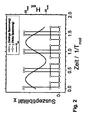
Fig. 2 ein magnetisches Material im sinusförmigen Wechselmagnetfeld mit Rechteckverlauf der Suszeptibilität, -
Fig. 3 die Koeffizienten der Fourier-Reihe mit Vielfachen der doppelten Modulationsfrequenz, -
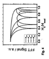
Fig. 4 die lokalen Minima in Abhängigkeit vom mechanischen Material-Spannungszustand, -
Fig. 5a die Fourier-Koeffizienten als Abstandsfunktion zwischen Material und Messspule, -
Fig. 5b die charakteristischen Minima bei Abstandsvergrößerung, -
Fig. 6 die Rechtecksignal-Tastveränderung bei variiertem H mod., -
Fig. 7 die Nullstellen der Fourier-Koeffizienten für verschiedene H mod./H k-Verhältnisse, -
Fig. 8 das proportionales Material-Anisotropiefeld für Modulationsfeld mit Nullstellen sowie - Tab. 1 die Nullstellenzusammenstellung nach Gleichung (8).
- Ein ferromagnetisches, invers magnetostriktives Material wird einem Wechselmagnetfeld der Frequenz fmod. ausgesetzt. Die Größe des Wechselmagnetfeldes ist dabei so gewählt, dass das magnetische Material periodisch in die Sättigung gebracht wird. Daraus ergibt sich für die Magnetisierungskurve, dargestellt als Magnetisierung M des Materials als Funktion der externen Feldstärke H ext., ein charakteristischer Verlauf der Suszeptibilität

- Vereinfachend soll im Folgenden zunächst von einer idealisierten Magnetisierungskurve ausgegangen werden [
Fig. 1 ], die sich durch unten aufgeführte Eigenschaften beschreiben lässt: - Die Sättigungsmagnetisierung Ms wird bei der Feldstärke Hk erreicht,
- die Suszeptibilität x ist für kleine Feldstärken unter dem Anisotropiefeld H k konstant und > 0; für Felder H ext. > H k gilt x = 0. Damit gilt

- durch Anlegen einer äußeren mechanischen Zugspannung σ erhöht sich das Anisotropiefeld H k, die Sättigungsmagnetisierung Ms bleibt jedoch unverändert.
- Damit verringert sich die Suszeptibilität mit zunehmender mechanischer Spannung bei positiv magnetostriktive Materialien, wenn die Richtung des Magnetfeldes und die Zugrichtung senkrecht zueinander stehen.
- Damit lässt sich die Magnetisierungskurve durch

und die Suszeptibilität durch
beschreiben. - Unterliegt nun das Material mit obiger Magnetisierungskurve einem Wechselmagnetfeld H ext.(t) = H mod. sin(ωmod.t) mit ωmod. = 2πf mod. - wie in
Fig. 2 dargestellt - so ergibt sich für die Suszeptibilität ein Rechtecksignal mit den oberen und unteren Werten x und 0 respektive. Zu beachten ist weiterhin, dass sich neben der Amplitude des Rechtecksignals auch das Zeitintervall, in dem das Signal den oberen der beiden Werte einnimmt - entspricht dem Tastverhältnis - mit unterschiedlichen Spannungszuständen verändert. Die Suszeptibilität als Funktion der Zeit lässt sich schreiben als:
- Durch die Symmetrie der Magnetisierungskurve - es gilt M(-Hext.)=-M(Hext.) - hat das Rechtecksignal x(t) die halbe Periodendauer der Modulationsfrequenz f mod.. Es gilt somit für die Periodendauer T0 des Rechtecksignals:

- Nun lässt sich das Frequenzspektrum des Rechtecksignals mittels Fourier-Transformation entwickeln. Es gelten hierfür die bekannte Synthese- und Analysegleichung. Sie zeigen, dass jedes Signal eine Grundfrequenz und ein Vielfaches von ω0 haben, so dass ein periodisches Signal durch das Gleichungspaar a) der Synthesegleichung

und b) der Analysegleichung - auch als Fourier-Integral bekannt -
definiert ist,
wobei die Absolutwerte von a k den Koeffizienten der Fourier-Reihe mit der Grundfrequenz ω0 entsprechen. Der Koeffizient a 0 ist hierbei der konstante Anteil von x(t) und lässt sich bestimmen durch
- Für k ≠ 0 wird über das Intervall von


und mit ω0T0 =2π gilt weiter
- Der Zeitpunkt T1 lässt sich durch die Grenzen von Gleichung (3) im Verhältnis von Hk zu Hmod. ausdrücken. Aus Hk = H mod. sin(ωmod. T 1) folgt


und mit der Gleichung (6)
- Die Koeffizienten der Fourier-Reihe können damit für ein gegebenes Verhältnis von Hk zu Hmod. bestimmt werden. Die Koeffizienten für k = 1, ..., 4 sind in
Fig. 4 als Funktion dieses Verhältnisses abgebildet. Um das Rechtecksignal und seine Kanten mit geringem Fehler abzubilden, wäre eine Betrachtung bis hin zu hohen Harmonischen notwendig. Da die Amplitude mit steigendem k mit l/k abnimmt, werden in diesem Verfahren nur die ersten vier Harmonischen der Messfrequenz f0, d. h. die ersten vier geraden Harmonischen der Modulationsfrequenz fmod. für die Analyse herangezogen. Betrachtet man zudem eine reale Suszeptibilität als Funktion eines externen Magnetfeldes, so gleicht diese ohnehin eher einer Glockenkurve ohne die abrupten Sprünge des hier betrachteten Rechtecksignals. - Gemäß Gleichung (8) kann das Auftreten der Nullstellen der ak (für k = 1, ..., 4; siehe
Fig. 4 ) tabellarisch zusammengefasst werden. Tab. 1 zeigt hierfür eine der Möglichkeiten. Dabei ist in der ersten Zeile dasjenige Verhältnis von Hk zu Hmod. angegeben, bei dem eines oder mehrere der Fourier-Koeffizienten a k zu null wird. Der Arkussinus dieses Verhältnisses entspricht einem Bruchteil von π, welcher multipliziert mit 2k für bestimmte k ein Vielfaches von n ergibt. Dies wiederum führt zur Nullstelle des Fourier-Koeffizienten ak .Tabelle 1 0.3827 0.5000 0.7071 0.8660 0.9239 1.0000 π/8 π/6 π/4 π/3 3π/8 π/2 ak =0 für k= 4 3 2,4 3 4 1, 2, 3, 4 - Die Amplitude der Koeffizienten nimmt also exponentiell mit dem Abstand zwischen der Messspule und dem magnetischen Material ab. Die Koeffizienten lassen sich demnach durch

Figuren 5a und 5b stellen die Abhängigkeit der Koeffizient von x grafisch dar. - Die Fourier-Koeffizienten nehmen also exponentiell mit zunehmendem Abstand x zwischen Messspule und Material ab. Die charakteristischen lokalen Minima treten auch bei zunehmendem Abstand an den gleichen Hk zu Hmod auf.
- Das Verhältnis Hk zu Hmod ist demnach entscheidend für die Entstehung von lokalen Minima. So lässt sich umgekehrt auch für jeden Spannungszustand - gekennzeichnet durch ein bestimmtes Hk - das entsprechende Modulationsfeld finden, bei dem ein lokales Minimum auftritt. Die Fourier-Koeffizienten lassen sich nach Gleichung (7) auch für ein sich veränderndes Hmod bei konstantem Hk berechnen, wie in
Fig. 7 dargestellt. Die Werte des Modulationsfeldes, bei denen Nullstellen der jeweiligen ak für ein bestimmtes Hk auftreten, sind für k = 2, 3, 4 inFig. 8 gezeigt. Bei konstantem Hk bleibt die Magnetisierungskurve also unverändert. Das Rechtecksignal ändert sich somit bei Variation von Hmod. Allein in seinem Tastverhältnis. Die Fourier-Koeffizienten zeigen erneut die Nullstellen bei den entsprechenden Verhältnissen von Hk zu Hmod. , bzw. Hmod. Zu Hk. - Das Modulationsfeld, bei dem Nullstellen auftreten, ist demnach proportional zum Anisotropiefeld des Materials.
- Durch die Variation des Modulationsfeldes lässt sich also ein bestimmter Fourier-Koeffizient, z. B. a 4, auf den Wert null minimieren. Der Wert des Modulationsfeldes ist in dieser Nullstelle entsprechend proportional zum Anisotropiefeld des Materials, das wiederum durch den Spannungszustand gekennzeichnet ist. Ändert sich der Spannungszustand des Materials und damit Hk , kann das Modulationsfeld entsprechend angepasst werden, damit der Fourier-Koeffizient weiterhin null beträgt. Diese Möglichkeit der Variation des Modulationsfeldes H mod. Liefert also eine weitere Möglichkeit der Signalauswertung.
Claims (3)
- Verfahren zur Bestimmung mechanischer Eigenschaften magnetostriktiver Materialien, mit den folgenden Schritten:Einbringen des Materials in ein externes Wechselmagnetfeld unter periodischem Sättigen des magnetischen Materials,Aufbringen einer senkrecht zu der Magnetfeldrichtung verlaufenden wechselnden mechanischen Zugspannungsbeanspruchung,Gewinnen eines charakteristischen Verlaufs der Suszeptibilität bei verschiedenen Zugbeanspruchungen,Bestimmen der Koeffizienten einer Fourier-Reihe aus den Verläufen der Suszeptibiltät undErmitteln der Koeffizienten der sich als lokale Minima darstellenden Nullstellen der Fourier-Funktion.
- Verfahren nach Anspruch 1, gekennzeichnet durch Berücksichtigen allein der Nullstellen einer bestimmten harmonischen Oberschwingung.
- Verfahren nach Anspruch 1 oder 2, gekennzeichnet durch Anpassen des modulierten Magnetfelds derart, dass der Fourier-Koeffizient bei den verschiedenen Zugspannungsbelastungen des magnetischen Materials null wird.
Applications Claiming Priority (2)
| Application Number | Priority Date | Filing Date | Title |
|---|---|---|---|
| DE201010005550 DE102010005550A1 (de) | 2010-01-22 | 2010-01-22 | Verfahren zur Bestimmung mechanischer Eigenschaften magnetostriktiver Materialien |
| PCT/DE2011/000058 WO2011088823A2 (de) | 2010-01-22 | 2011-01-20 | Verfahren zur bestimmung mechanischer eigenschaften magnetostriktiver materialien |
Publications (2)
| Publication Number | Publication Date |
|---|---|
| EP2526434A2 EP2526434A2 (de) | 2012-11-28 |
| EP2526434B1 true EP2526434B1 (de) | 2015-01-07 |
Family
ID=44307299
Family Applications (1)
| Application Number | Title | Priority Date | Filing Date |
|---|---|---|---|
| EP11734388.9A Not-in-force EP2526434B1 (de) | 2010-01-22 | 2011-01-20 | Verfahren zur bestimmung mechanischer eigenschaften magnetostriktiver materialien |
Country Status (3)
| Country | Link |
|---|---|
| EP (1) | EP2526434B1 (de) |
| DE (1) | DE102010005550A1 (de) |
| WO (1) | WO2011088823A2 (de) |
Citations (2)
| Publication number | Priority date | Publication date | Assignee | Title |
|---|---|---|---|---|
| DE4218799A1 (de) * | 1992-06-06 | 1993-12-16 | Brandmeier Thomas Dr | Verfahren zur Verschleißerkennung an Werkzeugmaschinen durch dynamische Kraftmessung mittels des magnetoelastischen Effekts |
| US6433543B1 (en) * | 2002-01-04 | 2002-08-13 | Mohsen Shahinpoor | Smart fiber optic magnetometer |
Family Cites Families (5)
| Publication number | Priority date | Publication date | Assignee | Title |
|---|---|---|---|---|
| US389855A (en) | 1888-09-18 | Nine one-hundbedths to julius th | ||
| US3898555A (en) | 1973-12-19 | 1975-08-05 | Tempo Instr Inc | Linear distance measuring device using a moveable magnet interacting with a sonic waveguide |
| DE3534460A1 (de) | 1985-05-24 | 1986-11-27 | Robert Bosch Gmbh, 7000 Stuttgart | Sensoranordnung |
| DE3620412A1 (de) | 1986-06-18 | 1987-12-23 | Bosch Gmbh Robert | Schaltungsanordnung zum betreiben eines magnetoelastischen sensors |
| DE3624846A1 (de) | 1986-07-23 | 1988-01-28 | Bosch Gmbh Robert | Vorrichtung zum beruehrungsfreien messen einer mechanischen spannung |
-
2010
- 2010-01-22 DE DE201010005550 patent/DE102010005550A1/de not_active Withdrawn
-
2011
- 2011-01-20 WO PCT/DE2011/000058 patent/WO2011088823A2/de not_active Ceased
- 2011-01-20 EP EP11734388.9A patent/EP2526434B1/de not_active Not-in-force
Patent Citations (2)
| Publication number | Priority date | Publication date | Assignee | Title |
|---|---|---|---|---|
| DE4218799A1 (de) * | 1992-06-06 | 1993-12-16 | Brandmeier Thomas Dr | Verfahren zur Verschleißerkennung an Werkzeugmaschinen durch dynamische Kraftmessung mittels des magnetoelastischen Effekts |
| US6433543B1 (en) * | 2002-01-04 | 2002-08-13 | Mohsen Shahinpoor | Smart fiber optic magnetometer |
Also Published As
| Publication number | Publication date |
|---|---|
| EP2526434A2 (de) | 2012-11-28 |
| DE102010005550A1 (de) | 2011-07-28 |
| WO2011088823A2 (de) | 2011-07-28 |
| WO2011088823A3 (de) | 2011-11-17 |
Similar Documents
| Publication | Publication Date | Title |
|---|---|---|
| EP0061520B1 (de) | Magnetkernloser Messwandler zum berührungslosen Messen eines Messstromes | |
| EP2291665B1 (de) | Stromsensoranordnung zur messung von strömen in einem primärleiter | |
| EP3308110B1 (de) | Verfahren und vorrichtung zur überprüfung der funktionsfähigkeit eines radar-basierten füllstandsmessgeräts | |
| WO2013007240A1 (de) | Verfahren und vorrichtung zur messung elektrischer ströme mit hilfe eines stromwandlers | |
| DE102014215109A1 (de) | Flux-Gate-Stromsensor mit zusätzlicher Frequenzmessung | |
| WO1996009516A1 (de) | Sensoranordnung und verfahren zur messwerterfassung mit der sensoranordnung | |
| DE102010025170A1 (de) | Vorrichtung zum Erzeugen eines Sensorsignals und Verfahren zur Bestimmung der Position eines Gebers | |
| EP1527324B1 (de) | Magnetoresistiver sensor | |
| EP3293499A1 (de) | Verfahren zum betreiben eines magnetisch-induktiven durchflussmessgeräts und magnetisch-induktives durchflussmessgerät | |
| DE102010011936B4 (de) | Verfahren und Einrichtung zur Bestimmung von geometrischen, magnetischen und/oder elektrischen Eigenschaften magnetischer, dielektrischer und/oder elektrisch leitfähiger Partikel in einer Probe | |
| DE2627954A1 (de) | Vibrationsdensitometer | |
| WO2019170483A1 (de) | Messen von mechanischen veränderungen | |
| WO2017032730A1 (de) | Verfahren und anordnung zur bestimmung der querempfindlichkeit von magnetfeldsensoren | |
| DE112005003226T5 (de) | Verfahren zum Messen eines schwachen Magnetfelds und Magnetfeldsensor mit verbesserter Empfindlichkeit | |
| DE102015013022A1 (de) | Magnetfeldmessvorrichtung | |
| EP2526434A2 (de) | Verfahren zur bestimmung mechanischer eigenschaften magnetostriktiver materialien | |
| DE60221855T2 (de) | Schätzung von zielsignalen durch einen dynamischen fluxgate-sensor | |
| DE2919983A1 (de) | Elektromagnetisches pruefverfahren | |
| DE102015003196B4 (de) | Vorrichtung und Verfahren zur Restwertverarbeitung bei der Ansteuerung eines Sensors | |
| DE4133619A1 (de) | Verfahren und vorrichtung zur messung des einschwingverhaltens | |
| EP3671196B1 (de) | System zur ermittlung eines alterungszustands eines elastomerprodukts | |
| DE102018216131B4 (de) | Verfahren und Vorrichtung zur gleichzeitigen Bestimmung der Temperatur- und Widerstandsänderung von Sensorwiderständen einer als Viertel- oder Halbbrücke ausgebildeten Brückenschaltung | |
| EP2430418B1 (de) | Messverfahren für sensorik | |
| WO2002086435A1 (de) | Berührungslose magnetoelastische sensoren | |
| DE102017217295A1 (de) | Drucksensor und Verfahren zum Messen eines Drucks mittels eines Drucksensors |
Legal Events
| Date | Code | Title | Description |
|---|---|---|---|
| PUAI | Public reference made under article 153(3) epc to a published international application that has entered the european phase |
Free format text: ORIGINAL CODE: 0009012 |
|
| 17P | Request for examination filed |
Effective date: 20120820 |
|
| AK | Designated contracting states |
Kind code of ref document: A2 Designated state(s): AL AT BE BG CH CY CZ DE DK EE ES FI FR GB GR HR HU IE IS IT LI LT LU LV MC MK MT NL NO PL PT RO RS SE SI SK SM TR |
|
| RIN1 | Information on inventor provided before grant (corrected) |
Inventor name: BECHTOLD, CHRISOPH Inventor name: QUANDT, ECKHARD Inventor name: THEDE, CLAAS Inventor name: TELIBAN, JULIAN Inventor name: CHEMNITZ, STEFFEN |
|
| DAX | Request for extension of the european patent (deleted) | ||
| 17Q | First examination report despatched |
Effective date: 20130611 |
|
| GRAP | Despatch of communication of intention to grant a patent |
Free format text: ORIGINAL CODE: EPIDOSNIGR1 |
|
| INTG | Intention to grant announced |
Effective date: 20140730 |
|
| GRAS | Grant fee paid |
Free format text: ORIGINAL CODE: EPIDOSNIGR3 |
|
| GRAA | (expected) grant |
Free format text: ORIGINAL CODE: 0009210 |
|
| AK | Designated contracting states |
Kind code of ref document: B1 Designated state(s): AL AT BE BG CH CY CZ DE DK EE ES FI FR GB GR HR HU IE IS IT LI LT LU LV MC MK MT NL NO PL PT RO RS SE SI SK SM TR |
|
| REG | Reference to a national code |
Ref country code: GB Ref legal event code: FG4D Free format text: NOT ENGLISH |
|
| REG | Reference to a national code |
Ref country code: CH Ref legal event code: EP |
|
| REG | Reference to a national code |
Ref country code: IE Ref legal event code: FG4D Free format text: LANGUAGE OF EP DOCUMENT: GERMAN |
|
| REG | Reference to a national code |
Ref country code: AT Ref legal event code: REF Ref document number: 706093 Country of ref document: AT Kind code of ref document: T Effective date: 20150215 |
|
| REG | Reference to a national code |
Ref country code: DE Ref legal event code: R096 Ref document number: 502011005562 Country of ref document: DE Effective date: 20150226 |
|
| RIN2 | Information on inventor provided after grant (corrected) |
Inventor name: TELIBAN, IULIAN Inventor name: CHEMNITZ, STEFFEN Inventor name: BECHTOLD, CHRISTOPH Inventor name: THEDE, CLAAS Inventor name: QUANDT, ECKHARD |
|
| REG | Reference to a national code |
Ref country code: NL Ref legal event code: VDEP Effective date: 20150107 |
|
| REG | Reference to a national code |
Ref country code: LT Ref legal event code: MG4D |
|
| PG25 | Lapsed in a contracting state [announced via postgrant information from national office to epo] |
Ref country code: BE Free format text: LAPSE BECAUSE OF NON-PAYMENT OF DUE FEES Effective date: 20150131 |
|
| PG25 | Lapsed in a contracting state [announced via postgrant information from national office to epo] |
Ref country code: FI Free format text: LAPSE BECAUSE OF FAILURE TO SUBMIT A TRANSLATION OF THE DESCRIPTION OR TO PAY THE FEE WITHIN THE PRESCRIBED TIME-LIMIT Effective date: 20150107 Ref country code: LT Free format text: LAPSE BECAUSE OF FAILURE TO SUBMIT A TRANSLATION OF THE DESCRIPTION OR TO PAY THE FEE WITHIN THE PRESCRIBED TIME-LIMIT Effective date: 20150107 Ref country code: SE Free format text: LAPSE BECAUSE OF FAILURE TO SUBMIT A TRANSLATION OF THE DESCRIPTION OR TO PAY THE FEE WITHIN THE PRESCRIBED TIME-LIMIT Effective date: 20150107 Ref country code: HR Free format text: LAPSE BECAUSE OF FAILURE TO SUBMIT A TRANSLATION OF THE DESCRIPTION OR TO PAY THE FEE WITHIN THE PRESCRIBED TIME-LIMIT Effective date: 20150107 Ref country code: ES Free format text: LAPSE BECAUSE OF FAILURE TO SUBMIT A TRANSLATION OF THE DESCRIPTION OR TO PAY THE FEE WITHIN THE PRESCRIBED TIME-LIMIT Effective date: 20150107 Ref country code: BG Free format text: LAPSE BECAUSE OF FAILURE TO SUBMIT A TRANSLATION OF THE DESCRIPTION OR TO PAY THE FEE WITHIN THE PRESCRIBED TIME-LIMIT Effective date: 20150407 Ref country code: NO Free format text: LAPSE BECAUSE OF FAILURE TO SUBMIT A TRANSLATION OF THE DESCRIPTION OR TO PAY THE FEE WITHIN THE PRESCRIBED TIME-LIMIT Effective date: 20150407 |
|
| REG | Reference to a national code |
Ref country code: CH Ref legal event code: PL |
|
| PG25 | Lapsed in a contracting state [announced via postgrant information from national office to epo] |
Ref country code: IS Free format text: LAPSE BECAUSE OF FAILURE TO SUBMIT A TRANSLATION OF THE DESCRIPTION OR TO PAY THE FEE WITHIN THE PRESCRIBED TIME-LIMIT Effective date: 20150507 Ref country code: GR Free format text: LAPSE BECAUSE OF FAILURE TO SUBMIT A TRANSLATION OF THE DESCRIPTION OR TO PAY THE FEE WITHIN THE PRESCRIBED TIME-LIMIT Effective date: 20150408 Ref country code: PL Free format text: LAPSE BECAUSE OF FAILURE TO SUBMIT A TRANSLATION OF THE DESCRIPTION OR TO PAY THE FEE WITHIN THE PRESCRIBED TIME-LIMIT Effective date: 20150107 Ref country code: RS Free format text: LAPSE BECAUSE OF FAILURE TO SUBMIT A TRANSLATION OF THE DESCRIPTION OR TO PAY THE FEE WITHIN THE PRESCRIBED TIME-LIMIT Effective date: 20150107 Ref country code: NL Free format text: LAPSE BECAUSE OF FAILURE TO SUBMIT A TRANSLATION OF THE DESCRIPTION OR TO PAY THE FEE WITHIN THE PRESCRIBED TIME-LIMIT Effective date: 20150107 Ref country code: LV Free format text: LAPSE BECAUSE OF FAILURE TO SUBMIT A TRANSLATION OF THE DESCRIPTION OR TO PAY THE FEE WITHIN THE PRESCRIBED TIME-LIMIT Effective date: 20150107 |
|
| REG | Reference to a national code |
Ref country code: DE Ref legal event code: R097 Ref document number: 502011005562 Country of ref document: DE |
|
| PG25 | Lapsed in a contracting state [announced via postgrant information from national office to epo] |
Ref country code: MC Free format text: LAPSE BECAUSE OF FAILURE TO SUBMIT A TRANSLATION OF THE DESCRIPTION OR TO PAY THE FEE WITHIN THE PRESCRIBED TIME-LIMIT Effective date: 20150107 Ref country code: DK Free format text: LAPSE BECAUSE OF FAILURE TO SUBMIT A TRANSLATION OF THE DESCRIPTION OR TO PAY THE FEE WITHIN THE PRESCRIBED TIME-LIMIT Effective date: 20150107 Ref country code: RO Free format text: LAPSE BECAUSE OF FAILURE TO SUBMIT A TRANSLATION OF THE DESCRIPTION OR TO PAY THE FEE WITHIN THE PRESCRIBED TIME-LIMIT Effective date: 20150107 Ref country code: CZ Free format text: LAPSE BECAUSE OF FAILURE TO SUBMIT A TRANSLATION OF THE DESCRIPTION OR TO PAY THE FEE WITHIN THE PRESCRIBED TIME-LIMIT Effective date: 20150107 Ref country code: LI Free format text: LAPSE BECAUSE OF NON-PAYMENT OF DUE FEES Effective date: 20150131 Ref country code: SK Free format text: LAPSE BECAUSE OF FAILURE TO SUBMIT A TRANSLATION OF THE DESCRIPTION OR TO PAY THE FEE WITHIN THE PRESCRIBED TIME-LIMIT Effective date: 20150107 Ref country code: EE Free format text: LAPSE BECAUSE OF FAILURE TO SUBMIT A TRANSLATION OF THE DESCRIPTION OR TO PAY THE FEE WITHIN THE PRESCRIBED TIME-LIMIT Effective date: 20150107 Ref country code: CH Free format text: LAPSE BECAUSE OF NON-PAYMENT OF DUE FEES Effective date: 20150131 |
|
| REG | Reference to a national code |
Ref country code: IE Ref legal event code: MM4A |
|
| PLBE | No opposition filed within time limit |
Free format text: ORIGINAL CODE: 0009261 |
|
| STAA | Information on the status of an ep patent application or granted ep patent |
Free format text: STATUS: NO OPPOSITION FILED WITHIN TIME LIMIT |
|
| 26N | No opposition filed |
Effective date: 20151008 |
|
| REG | Reference to a national code |
Ref country code: FR Ref legal event code: PLFP Year of fee payment: 6 |
|
| PG25 | Lapsed in a contracting state [announced via postgrant information from national office to epo] |
Ref country code: IE Free format text: LAPSE BECAUSE OF NON-PAYMENT OF DUE FEES Effective date: 20150120 |
|
| PG25 | Lapsed in a contracting state [announced via postgrant information from national office to epo] |
Ref country code: SI Free format text: LAPSE BECAUSE OF FAILURE TO SUBMIT A TRANSLATION OF THE DESCRIPTION OR TO PAY THE FEE WITHIN THE PRESCRIBED TIME-LIMIT Effective date: 20150107 |
|
| PG25 | Lapsed in a contracting state [announced via postgrant information from national office to epo] |
Ref country code: MT Free format text: LAPSE BECAUSE OF FAILURE TO SUBMIT A TRANSLATION OF THE DESCRIPTION OR TO PAY THE FEE WITHIN THE PRESCRIBED TIME-LIMIT Effective date: 20150107 |
|
| REG | Reference to a national code |
Ref country code: FR Ref legal event code: PLFP Year of fee payment: 7 |
|
| PG25 | Lapsed in a contracting state [announced via postgrant information from national office to epo] |
Ref country code: HU Free format text: LAPSE BECAUSE OF FAILURE TO SUBMIT A TRANSLATION OF THE DESCRIPTION OR TO PAY THE FEE WITHIN THE PRESCRIBED TIME-LIMIT; INVALID AB INITIO Effective date: 20110120 Ref country code: SM Free format text: LAPSE BECAUSE OF FAILURE TO SUBMIT A TRANSLATION OF THE DESCRIPTION OR TO PAY THE FEE WITHIN THE PRESCRIBED TIME-LIMIT Effective date: 20150107 |
|
| PG25 | Lapsed in a contracting state [announced via postgrant information from national office to epo] |
Ref country code: CY Free format text: LAPSE BECAUSE OF FAILURE TO SUBMIT A TRANSLATION OF THE DESCRIPTION OR TO PAY THE FEE WITHIN THE PRESCRIBED TIME-LIMIT Effective date: 20150107 |
|
| PG25 | Lapsed in a contracting state [announced via postgrant information from national office to epo] |
Ref country code: PT Free format text: LAPSE BECAUSE OF FAILURE TO SUBMIT A TRANSLATION OF THE DESCRIPTION OR TO PAY THE FEE WITHIN THE PRESCRIBED TIME-LIMIT Effective date: 20150507 |
|
| PG25 | Lapsed in a contracting state [announced via postgrant information from national office to epo] |
Ref country code: TR Free format text: LAPSE BECAUSE OF FAILURE TO SUBMIT A TRANSLATION OF THE DESCRIPTION OR TO PAY THE FEE WITHIN THE PRESCRIBED TIME-LIMIT Effective date: 20150107 |
|
| PG25 | Lapsed in a contracting state [announced via postgrant information from national office to epo] |
Ref country code: LU Free format text: LAPSE BECAUSE OF NON-PAYMENT OF DUE FEES Effective date: 20150120 |
|
| REG | Reference to a national code |
Ref country code: FR Ref legal event code: PLFP Year of fee payment: 8 |
|
| PG25 | Lapsed in a contracting state [announced via postgrant information from national office to epo] |
Ref country code: MK Free format text: LAPSE BECAUSE OF FAILURE TO SUBMIT A TRANSLATION OF THE DESCRIPTION OR TO PAY THE FEE WITHIN THE PRESCRIBED TIME-LIMIT Effective date: 20150107 |
|
| PG25 | Lapsed in a contracting state [announced via postgrant information from national office to epo] |
Ref country code: AL Free format text: LAPSE BECAUSE OF FAILURE TO SUBMIT A TRANSLATION OF THE DESCRIPTION OR TO PAY THE FEE WITHIN THE PRESCRIBED TIME-LIMIT Effective date: 20150107 |
|
| PGFP | Annual fee paid to national office [announced via postgrant information from national office to epo] |
Ref country code: FR Payment date: 20230123 Year of fee payment: 13 Ref country code: AT Payment date: 20230118 Year of fee payment: 13 |
|
| PGFP | Annual fee paid to national office [announced via postgrant information from national office to epo] |
Ref country code: IT Payment date: 20230131 Year of fee payment: 13 Ref country code: GB Payment date: 20230124 Year of fee payment: 13 Ref country code: DE Payment date: 20230119 Year of fee payment: 13 |
|
| REG | Reference to a national code |
Ref country code: DE Ref legal event code: R119 Ref document number: 502011005562 Country of ref document: DE |
|
| REG | Reference to a national code |
Ref country code: AT Ref legal event code: MM01 Ref document number: 706093 Country of ref document: AT Kind code of ref document: T Effective date: 20240120 |
|
| GBPC | Gb: european patent ceased through non-payment of renewal fee |
Effective date: 20240120 |
|
| PG25 | Lapsed in a contracting state [announced via postgrant information from national office to epo] |
Ref country code: DE Free format text: LAPSE BECAUSE OF NON-PAYMENT OF DUE FEES Effective date: 20240801 |
|
| PG25 | Lapsed in a contracting state [announced via postgrant information from national office to epo] |
Ref country code: GB Free format text: LAPSE BECAUSE OF NON-PAYMENT OF DUE FEES Effective date: 20240120 |
|
| PG25 | Lapsed in a contracting state [announced via postgrant information from national office to epo] |
Ref country code: FR Free format text: LAPSE BECAUSE OF NON-PAYMENT OF DUE FEES Effective date: 20240131 |
|
| PG25 | Lapsed in a contracting state [announced via postgrant information from national office to epo] |
Ref country code: AT Free format text: LAPSE BECAUSE OF NON-PAYMENT OF DUE FEES Effective date: 20240120 |
|
| PG25 | Lapsed in a contracting state [announced via postgrant information from national office to epo] |
Ref country code: GB Free format text: LAPSE BECAUSE OF NON-PAYMENT OF DUE FEES Effective date: 20240120 Ref country code: FR Free format text: LAPSE BECAUSE OF NON-PAYMENT OF DUE FEES Effective date: 20240131 Ref country code: DE Free format text: LAPSE BECAUSE OF NON-PAYMENT OF DUE FEES Effective date: 20240801 Ref country code: AT Free format text: LAPSE BECAUSE OF NON-PAYMENT OF DUE FEES Effective date: 20240120 |
|
| PG25 | Lapsed in a contracting state [announced via postgrant information from national office to epo] |
Ref country code: IT Free format text: LAPSE BECAUSE OF NON-PAYMENT OF DUE FEES Effective date: 20240120 |