EP2525071A1 - Continuous detonation wave engine and aircraft provided with such an engine - Google Patents
Continuous detonation wave engine and aircraft provided with such an engine Download PDFInfo
- Publication number
- EP2525071A1 EP2525071A1 EP12290157A EP12290157A EP2525071A1 EP 2525071 A1 EP2525071 A1 EP 2525071A1 EP 12290157 A EP12290157 A EP 12290157A EP 12290157 A EP12290157 A EP 12290157A EP 2525071 A1 EP2525071 A1 EP 2525071A1
- Authority
- EP
- European Patent Office
- Prior art keywords
- detonation
- chamber
- injection
- detonation chamber
- engine
- Prior art date
- Legal status (The legal status is an assumption and is not a legal conclusion. Google has not performed a legal analysis and makes no representation as to the accuracy of the status listed.)
- Granted
Links
Images

Classifications
-
- F—MECHANICAL ENGINEERING; LIGHTING; HEATING; WEAPONS; BLASTING
- F02—COMBUSTION ENGINES; HOT-GAS OR COMBUSTION-PRODUCT ENGINE PLANTS
- F02K—JET-PROPULSION PLANTS
- F02K7/00—Plants in which the working fluid is used in a jet only, i.e. the plants not having a turbine or other engine driving a compressor or a ducted fan; Control thereof
- F02K7/08—Plants in which the working fluid is used in a jet only, i.e. the plants not having a turbine or other engine driving a compressor or a ducted fan; Control thereof the jet being continuous
-
- F—MECHANICAL ENGINEERING; LIGHTING; HEATING; WEAPONS; BLASTING
- F02—COMBUSTION ENGINES; HOT-GAS OR COMBUSTION-PRODUCT ENGINE PLANTS
- F02K—JET-PROPULSION PLANTS
- F02K9/00—Rocket-engine plants, i.e. plants carrying both fuel and oxidant therefor; Control thereof
- F02K9/42—Rocket-engine plants, i.e. plants carrying both fuel and oxidant therefor; Control thereof using liquid or gaseous propellants
- F02K9/60—Constructional parts; Details not otherwise provided for
- F02K9/62—Combustion or thrust chambers
-
- F—MECHANICAL ENGINEERING; LIGHTING; HEATING; WEAPONS; BLASTING
- F23—COMBUSTION APPARATUS; COMBUSTION PROCESSES
- F23R—GENERATING COMBUSTION PRODUCTS OF HIGH PRESSURE OR HIGH VELOCITY, e.g. GAS-TURBINE COMBUSTION CHAMBERS
- F23R3/00—Continuous combustion chambers using liquid or gaseous fuel
- F23R3/42—Continuous combustion chambers using liquid or gaseous fuel characterised by the arrangement or form of the flame tubes or combustion chambers
- F23R3/425—Combustion chambers comprising a tangential or helicoidal arrangement of the flame tubes
-
- F—MECHANICAL ENGINEERING; LIGHTING; HEATING; WEAPONS; BLASTING
- F23—COMBUSTION APPARATUS; COMBUSTION PROCESSES
- F23R—GENERATING COMBUSTION PRODUCTS OF HIGH PRESSURE OR HIGH VELOCITY, e.g. GAS-TURBINE COMBUSTION CHAMBERS
- F23R7/00—Intermittent or explosive combustion chambers
-
- F—MECHANICAL ENGINEERING; LIGHTING; HEATING; WEAPONS; BLASTING
- F02—COMBUSTION ENGINES; HOT-GAS OR COMBUSTION-PRODUCT ENGINE PLANTS
- F02K—JET-PROPULSION PLANTS
- F02K7/00—Plants in which the working fluid is used in a jet only, i.e. the plants not having a turbine or other engine driving a compressor or a ducted fan; Control thereof
Definitions
- the present invention relates to a continuous detonation wave engine operating with a detonating fuel / oxidant mixture, and a flying machine which is provided with such a motor.
- thermodynamic detonation cycle can provide the same benefits in terms of energy efficiency. Indeed, a detonation cycle is very close to a constant volume cycle (the reaction is very fast in a very low thickness of mixture which does not have the temporal possibility to expand to limit the pressure increase) and corresponds to a thermodynamic efficiency still a little better.
- a PDE-type pulsed detonation engine Pulsed Detonation Engine
- an overpressure exists on the closed end and momentarily creates a thrust. It is then necessary to wait for the emptying of the hot gases resulting from the chemical reaction in the tube, then its filling in fresh mixture, before being able to initiate a new detonation wave and obtain a new thrust pulse.
- the pulsed nature of the thrust (operating from 50 to 200 Hz) generates a very severe vibratory environment for the rest of the machine and, moreover, requires to bring energy at each cycle to initiate the detonation, which can be a major problem of overall efficiency when one seeks to use fuel / oxidant pairs with little detonation.
- These characteristics limit its use to very specific applications (for example simple and inexpensive subsonic systems) or to very complex systems associating several PDE-type tubes.
- a continuous detonation engine of the CDWE type Continuous Detonation Wave Engine
- a continuous production of hot gases from self-sustaining detonation waves is generated in an annular chamber.
- a fuel / oxidant mixture is permanently injected at one end of the annular chamber.
- a detonation wave is then initiated. This wave propagates circumferentially in the fresh detonation mixture, while the hot gases it produces relax in the rest of the annular chamber.
- the injection of fresh mixture is permanent, when the wave returns to its starting point, it meets fresh mixture again and continues its circumferential movement which becomes continuous.
- annular chamber in which a series of circumferential detonation waves, traveling at a frequency of several kHz (up to 30 kHz), produces hot gases which expand towards the open end of the chamber.
- a gas generator which, as soon as they leave the detonation chamber, constitute a supersonic flow whose characteristics are relatively uniform.
- this engine of the CDWE type lies in the fact that, from the point of view of the thermodynamic cycle, the detonation potentially has (as for a PDE engine) a yield of 1 5 to 25% greater than that of a combustion with constant pressure.
- its operating principle avoids the generation of a very severe vibratory environment, as for a pulsed detonation PDE engine.
- this annular chamber comprises at the upstream end a transverse surface (called injection bottom hereinafter) which represents a ring shape, that is to say of constant width and whose length is defined according to a general line forming a closed curve, usually a closed circle.
- injection bottom represents a transverse surface
- the maximum performance can only be achieved in a relatively narrow range of local operating conditions (including the richness of the fuel / oxidant mixture). Therefore, it is difficult to design an annular chamber operating in a very broad field of use while respecting in every respect of this room the conditions required to obtain satisfactory energy efficiency.
- the object of the present invention is to improve the aforementioned continuous detonation engine by, in particular, overcoming these disadvantages.
- a continuous detonation wave motor which comprises a detonation chamber which does not have (and is not limited to) an annular (closed) shape, but may have many other forms different (open), specified below.
- This detonation chamber comprises, in fact, an elongated upstream injection bottom which may have any length of any open shape, in particular rectilinear or curved, but not closed to the difference of an annular chamber.
- This chamber further comprises two walls, preferably parallel, which extend on either side of this injection bottom.
- Said chamber thus has a three-dimensional geometric shape having faces (planar or not) which meet at edges.
- Said chamber may, in particular, be in the form of a hexahedron (polyhedron with six flat faces), and in particular a parallelepiped (hexahedron with parallel faces in pairs).
- the chamber may for example take the general shape of a rectangular parallelepiped (all of whose faces are rectangles).
- the possible applications of said motor are considerably increased compared with a conventional annular detonation chamber engine, and the aforementioned disadvantages can be overcome. , as specified below.
- the ends of the detonation chamber (at each end of the injection bottom) can be opened or closed, independently of one another, and initiation (carried out by said priming means) can be located anywhere along the injection bed of the chamber.
- the motor may advantageously comprise at least one cooling circuit of said detonation chamber, in which fuel can be circulated before it is injected into the latter.
- said cooling circuit extends along at least one side wall of said detonation chamber over at least a part of its length.
- said detonation chamber has at the injection bottom a bifurcation to create, beyond the latter, at least two elongated branches, each of which is fed detonating mixture by said injection system, which allows to create two propulsive lines by propagation of waves in the two branches.
- said injection system may be formed so as to feed each of these branches over a greater or lesser length and thus provide a possibility of control (vector thrust) of the flying machine equipped with said engine.
- said hybrid chamber takes the form of an annular detonation chamber, which is provided with concentric extensions (or branches) with variable feed lengths. These concentric extensions may be arranged inside said annular detonation chamber or outside thereof. It is then easy to modulate the thrust continuously, by feeding a longer or shorter length of fuel extensions (or fuel and oxidant for a rocket system). In the same way, one can easily ensure a control of the thrust orientation (for a ramjet or a rocket).
- the present invention also relates to a propulsion system (for example of the ramjet, turbomachine or rocket type) for a flying machine, which is provided with at least one continuous detonation wave engine, such as the one mentioned above.
- a propulsion system for example of the ramjet, turbomachine or rocket type
- a flying machine which is provided with at least one continuous detonation wave engine, such as the one mentioned above.
- this propulsion system is provided with at least two engines of this type, each of which comprises an injection system capable of modulating the injection.
- the present invention further relates to a flying machine, in particular an aircraft or a missile, which is provided with a motor and / or a propulsion system, such as those mentioned above.
- the engine 1 according to the invention and shown schematically on the figure 1 is a continuous detonation wave engine and is part of a propulsion system 2 for use in the field of aeronautics and / or space, being mounted on a flying machine.
- said detonation chamber 3 comprises, at the upstream end 5 (relative to said direction E), at the inlet, a transverse surface called injection bottom 10.
- This surface is transverse to the longitudinal direction of the chamber 3, which is defined generally along the general flow direction E of the gases.
- This injection bottom 10 has a length L1 which is defined along an open line, so as to form a detonation chamber 3 having an elongate shape in the transverse plane, and not annular.
- the width L2 of the injection bottom 10 it may be variable, but is preferably constant.
- the chamber 3 may in particular have the general shape of any hexahedron (polyhedron with six flat faces), and in particular that of a parallelepiped (hexahedron with parallel faces in pairs).
- the length of the injection bottom 10 is defined along a curved line, as illustrated for example by a line 17.
- the chamber 3 may, for example, take the form of a rectangular parallelepiped (all of whose faces are plane and are rectangles), as represented on the figure 2 .
- the engine 1 comprises a detonation chamber 3 which does not have (and is not limited to) an annular shape, but may have many other different forms.
- said injection system 4 is arranged to inject the fuel / oxidant mixture at the level of at least one portion 20 of said injection nozzle 10, as shown in FIG. figure 2 .
- This particular injection system 4 is formed so as to generate (together with the wave initiated by the priming means 8) particular local conditions, which make it possible to create in the detonation chamber 3 the detonation wave train. (primed naturally).
- the particular local conditions for creating this detonation wave train are likely to be defined by a person skilled in the art, particularly empirically.
- the usual priming means 8 for example a wire to be exploded or a pre-detonation tube
- a detonation wave 8 which then propagates. in said mixture in the longitudinal direction (arrow F) of the injection bottom 10 and is responsible for successive detonation waves 22 initiated automatically.
- This wave propagates in the fresh detonation mixture along the injection bottom 10, while the hot gases it produces relax in the rest of the chamber 3 (as shown by lines 23 illustrating the detonation products detonation ) and will be discharged through the open end 9 of the detonation chamber 3.
- These hot gases which expand towards the open end 9 of the chamber 3 can be used in different ways, in particular by being accelerated by a nozzle to obtain a push.
- the detonation wave degenerates into a simple compression wave 24, as shown in FIG. figure 2 .
- various injection zones 25 have been provided, only some of which are fed (arrows 26).
- the ends 15 and 16 of the detonation chamber 3 can be opened or closed, independently of one another.
- the initiation (implemented by the priming means 8) can be located anywhere along the injection bottom 10.
- the possible applications of the engine 1 are considerably increased, compared to a conventional engine with an exclusively annular detonation chamber.
- the injection system 4 injects the usual fuel separately from the air. There is therefore no provision for premix injection, which avoids any risk of ignition upstream of the detonation chamber 3.
- a storable fuel such as a liquid hydrocarbon it is also possible to provide a regenerative circuit (not shown) making it possible to pre-vaporize the fuel (before its injection) and thus to obtain satisfactory mixing and detonation conditions without premixing.
- this regenerative (or cooling) circuit in which fuel flows, extends along at least one side wall of said detonation chamber 3, over at least a part of its length.
- said injection system 4 is capable of injecting a variable length along said injection bottom 10. It is thus possible to provide different injection zones 25 along the injection bottom. 10, of which a variable number are likely to be fed (arrows 26 of the figure 2 ). It is possible to provide separate injection means for these different injection zones 25.
- two engines 1 of this type are mounted on a flying machine so as to generate propulsions respectively on either side of an axis of rotation, one can generate a rotation of the flying machine around this axis by realizing a asymmetrical injection.
- a motor 1 it is possible to mount such a motor 1 on each of the wings of an aircraft (not shown), the injection bottom 10 of the chamber 3 being defined each time along the trailing edge of the corresponding wing, and create a yaw moment by performing different injections on these two engines 1.
- a propulsion system 2 comprising a a plurality of motors 1 (variable feed length).
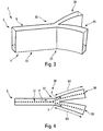
- said detonation chamber 3 has a bifurcation 27 at the injection bottom 10, as shown in FIGS. Figures 3 and 4 so as to create, beyond this bifurcation 27, at least two elongate branches 28 and 29 and thereby form a bifurcation chamber 30.
- Each of these branches 28 and 29 is supplied with a detonating mixture by said injection system 4, as illustrated in FIG. figure 4 by sequences 31 of points representing injection lines.
- This particular embodiment makes it possible to create two propulsive lines (or more) by propagation of the waves in the two branches 28 and 29 (or more).
- each engine 1 comprises, in addition to a detonation chamber, all the aforementioned means, in particular the injection system 4 and the priming means 8, which are necessary for its operation, even if for reasons of simplification of drawing, we have essentially represented the rooms on the Figures 3 and 4 , as well as on Figures 5 to 7 .
- the direction of movement of the detonation waves 22 has been indicated by means of arrows F.
- the injection system 4 can feed each of the branches 28 and 29 over a greater or lesser length, as illustrated by double arrows D1 and D2 on the figure 4 , and thus to offer a possibility of carrying out a vector control of the thrust by dissymmetrization of the injection conditions (ie without a steerable nozzle) of the flying machine equipped with said engine 1.
- These branches 28 and 29 can thus be powered on variable lengths. in time and independently of each other.
- annular chamber 33 of this hybrid chamber 34 can also be connected, via one or more bifurcations 27, to one or more extensions (or branches) additional.
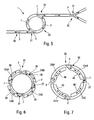
- a hybrid chamber 37, 38 can be provided which takes the form of an annular detonation chamber 36, provided (via bifurcations 27) with extensions 39, 40.
- These extensions 39, 40 are concentric with respect to the annular chamber 36.
- these extensions 39, 40 for example four in number, are uniformly distributed over the periphery (internal or external) of the annular chamber 36 and may have variable feed lengths, as illustrated by arrows D3A at D3B and D4A at D4B.
- the concentric extensions 39 are arranged radially inside said annular detonation chamber 36, whereas in the variant of realization of the figure 7 the concentric extensions 40 are arranged radially outside said annular detonation chamber 36.
- Such a hybrid chamber 37, 38 may in particular be used to replace a simple annular chamber, or concentric annular chambers, in a ramjet, a turbomachine or a rocket engine.
Abstract
Description
La présente invention concerne un moteur à onde de détonation continue fonctionnant avec un mélange combustible/oxydant détonant, ainsi qu'un engin volant qui est pourvu d'un tel moteur.The present invention relates to a continuous detonation wave engine operating with a detonating fuel / oxidant mixture, and a flying machine which is provided with such a motor.
On sait que la quasi-totalité des systèmes propulsifs utilisés dans le domaine de l'aéronautique et de l'espace sont basés sur un cycle thermodynamique de combustion à pression constante.It is known that almost all propellant systems used in aeronautics and space are based on a constant pressure combustion thermodynamic cycle.
On sait également que l'emploi d'un cycle thermodynamique de combustion à volume constant permet d'augmenter sensiblement la performance théorique d'un moteur (de 15 à 25%). Cependant, en raison des vitesses de déplacement de la plupart des aéronefs, la réalisation d'une combustion à volume constant s'avère assez difficile et conduit à des systèmes complexes et difficiles à mettre au point.It is also known that the use of a constant volume combustion thermodynamic cycle makes it possible to substantially increase the theoretical performance of an engine (from 15 to 25%). However, because of the travel speeds of most aircraft, achieving constant volume combustion is quite difficult and leads to complex and difficult to develop systems.
L'emploi d'un cycle thermodynamique de détonation peut apporter les mêmes avantages en termes d'efficacité énergétique. En effet, un cycle de détonation est très proche d'un cycle à volume constant (la réaction se fait très rapidement dans une épaisseur très faible de mélange qui n'a pas la possibilité temporelle de se dilater pour limiter l'augmentation de pression) et correspond à un rendement thermodynamique encore un peu meilleur.The use of a thermodynamic detonation cycle can provide the same benefits in terms of energy efficiency. Indeed, a detonation cycle is very close to a constant volume cycle (the reaction is very fast in a very low thickness of mixture which does not have the temporal possibility to expand to limit the pressure increase) and corresponds to a thermodynamic efficiency still a little better.
Comme moteur à détonation, on connaît un moteur à détonation pulsée de type PDE (« Pulsed Detonation Engine » en anglais), pour lequel on remplit un tube, fermé à l'une de ses extrémités, avec un mélange frais combustible/oxydant, puis on initie une détonation dans ce mélange frais. Pendant tout le temps que l'onde de détonation se déplace sur la longueur du tube, une surpression existe sur l'extrémité fermée et crée momentanément une poussée. Il faut alors attendre la vidange des gaz chauds issus de la réaction chimique dans le tube, puis son remplissage en mélange frais, avant de pouvoir initier une nouvelle onde de détonation et obtenir une nouvelle impulsion de poussée.As a detonation engine, a PDE-type pulsed detonation engine (Pulsed Detonation Engine) is known, for which a tube, closed at one of its ends, is filled with a fresh fuel / oxidant mixture, then a detonation is initiated in this fresh mixture. As the detonation wave travels along the length of the tube, an overpressure exists on the closed end and momentarily creates a thrust. It is then necessary to wait for the emptying of the hot gases resulting from the chemical reaction in the tube, then its filling in fresh mixture, before being able to initiate a new detonation wave and obtain a new thrust pulse.
La nature pulsée de la poussée (fonctionnement de 50 à 200 Hz) génère un environnement vibratoire très sévère pour le reste de l'engin et, de plus, nécessite d'apporter de l'énergie à chaque cycle pour initier la détonation, ce qui peut constituer un problème majeur d'efficacité globale quand on cherche à utiliser des couples combustible/comburant peu détonants. Ces caractéristiques limitent son emploi à des applications très particulières (par exemple des systèmes subsoniques simples et peu chers) ou à des systèmes très complexes associant plusieurs tubes de type PDE.The pulsed nature of the thrust (operating from 50 to 200 Hz) generates a very severe vibratory environment for the rest of the machine and, moreover, requires to bring energy at each cycle to initiate the detonation, which can be a major problem of overall efficiency when one seeks to use fuel / oxidant pairs with little detonation. These characteristics limit its use to very specific applications (for example simple and inexpensive subsonic systems) or to very complex systems associating several PDE-type tubes.
Pour remédier au problème de l'environnement vibratoire très sévère généré, a priori, par un moteur à détonation pulsée, on peut utiliser un moteur à détonation continue de type CDWE (« Continuous Detonation Wave Engine » en anglais). Dans un tel moteur à détonation continue, on génère dans une chambre annulaire une production continue de gaz chauds issus d'ondes de détonation auto-entretenues. Un mélange combustible/oxydant est injecté de façon permanente à l'une des extrémités de la chambre annulaire. On amorce alors une onde de détonation. Cette onde se propage de façon circonférentielle dans le mélange détonant frais, tandis que les gaz chauds qu'elle produit se détendent dans le reste de la chambre annulaire. Comme l'injection de mélange frais est permanente, lorsque l'onde revient à son point de départ, elle rencontre à nouveau du mélange frais et poursuit son mouvement circonférentiel qui devient donc continu.To remedy the problem of the very severe vibratory environment generated, a priori, by a pulsed detonation engine, it is possible to use a continuous detonation engine of the CDWE type ("Continuous Detonation Wave Engine"). In such a continuous detonation engine, a continuous production of hot gases from self-sustaining detonation waves is generated in an annular chamber. A fuel / oxidant mixture is permanently injected at one end of the annular chamber. A detonation wave is then initiated. This wave propagates circumferentially in the fresh detonation mixture, while the hot gases it produces relax in the rest of the annular chamber. As the injection of fresh mixture is permanent, when the wave returns to its starting point, it meets fresh mixture again and continues its circumferential movement which becomes continuous.
On dispose ainsi d'une chambre annulaire dans laquelle une série d'ondes de détonation circonférentielles, défilant à une fréquence de plusieurs kHz (jusqu'à 30 kHz), produit des gaz chauds qui se détendent vers l'extrémité ouverte de la chambre. On a donc, comme pour une chambre de combustion à pression constante, un générateur de gaz chauds qui constituent, dès la sortie de la chambre de détonation, un écoulement supersonique dont les caractéristiques sont relativement uniformes.There is thus an annular chamber in which a series of circumferential detonation waves, traveling at a frequency of several kHz (up to 30 kHz), produces hot gases which expand towards the open end of the chamber. As with a constant pressure combustion chamber, we have a gas generator which, as soon as they leave the detonation chamber, constitute a supersonic flow whose characteristics are relatively uniform.
L'intérêt de ce moteur de type CDWE réside dans le fait que, du point de vue du cycle thermodynamique, la détonation présente potentiellement (comme pour un moteur PDE) un rendement de 1 5 à 25 % supérieur à celui d'une combustion à pression constante. De plus, son principe de fonctionnement évite la génération d'un environnement vibratoire très sévère, comme pour un moteur PDE à détonation pulsée.The interest of this engine of the CDWE type lies in the fact that, from the point of view of the thermodynamic cycle, the detonation potentially has (as for a PDE engine) a yield of 1 5 to 25% greater than that of a combustion with constant pressure. In addition, its operating principle avoids the generation of a very severe vibratory environment, as for a pulsed detonation PDE engine.
Toutefois, les applications de ce moteur à détonation continue de type CDWE, sont limitées par l'utilisation d'une forme globalement annulaire fermée de la chambre de détonation. En effet, cette chambre annulaire comprend à l'extrémité amont une surface transversale (appelée fond d'injection ci-après) qui représente une forme en anneau, c'est-à-dire de largeur constante et dont la longueur est définie selon une ligne générale formant une courbe fermée, généralement un cercle fermé. Or, les performances maximales ne peuvent être atteintes que dans une plage relativement étroite de conditions locales de fonctionnement (notamment de richesse du mélange combustible/comburant). Dès lors, il est difficile de concevoir une chambre annulaire fonctionnant dans un très large domaine d'emploi tout en respectant en tout point de cette chambre les conditions requises pour obtenir une efficacité énergétique satisfaisante.However, the applications of this CDWE type continuous detonation engine are limited by the use of a generally annular closed shape of the detonation chamber. Indeed, this annular chamber comprises at the upstream end a transverse surface (called injection bottom hereinafter) which represents a ring shape, that is to say of constant width and whose length is defined according to a general line forming a closed curve, usually a closed circle. However, the maximum performance can only be achieved in a relatively narrow range of local operating conditions (including the richness of the fuel / oxidant mixture). Therefore, it is difficult to design an annular chamber operating in a very broad field of use while respecting in every respect of this room the conditions required to obtain satisfactory energy efficiency.
La présente invention a pour objet de perfectionner le moteur à détonation continue précité en remédiant notamment à ces inconvénients.The object of the present invention is to improve the aforementioned continuous detonation engine by, in particular, overcoming these disadvantages.
A cet effet, selon l'invention, ledit moteur à onde de détonation continue qui fonctionne avec un mélange combustible/oxydant détonant et qui comporte :
- au moins une chambre de détonation ;
- un système d'injection pour injecter de façon continue le mélange détonant dans ladite chambre de détonation au niveau d'une extrémité amont, ladite chambre de détonation comprenant un fond d'injection à ladite extrémité amont, ainsi que deux parois qui s'étendent de part et d'autre de ce fond d'injection ; et
- des moyens d'amorçage qui sont agencés dans ladite chambre de détonation, pour amorcer dans le mélange détonant, une onde de détonation qui se propage alors dans ledit mélange et est à l'origine d'ondes de détonation successives auto-initiées, de manière à générer une production continue de gaz chauds,
- at least one chamber of detonation;
- an injection system for continuously injecting the detonation mixture into said detonation chamber at an upstream end, said detonation chamber comprising an injection bottom at said upstream end, and two walls extending from both sides of this injection bottom; and
- priming means which are arranged in said detonation chamber, to initiate in the detonation mixture, a detonation wave which then propagates in said mixture and is at the origin of self-initiated successive detonation waves, so as to to generate a continuous production of hot gases,
Ainsi, grâce à l'invention, on obtient un moteur à onde de détonation continue qui comporte une chambre de détonation qui ne présente pas (et n'est pas limitée à) une forme annulaire (fermée), mais peut présenter de multiples autres formes différentes (ouvertes), précisées ci-dessous.Thus, thanks to the invention, there is obtained a continuous detonation wave motor which comprises a detonation chamber which does not have (and is not limited to) an annular (closed) shape, but may have many other forms different (open), specified below.
Cette chambre de détonation comprend, en effet, un fond d'injection amont allongé qui peut présenter une longueur de forme ouverte quelconque, en particulier rectiligne ou courbe, mais non fermée à la différence d'une chambre annulaire. Cette chambre comprend de plus deux parois, de préférence parallèles, qui s'étendent de part et d'autre de ce fond d'injection. Ladite chambre présente ainsi une forme géométrique à trois dimensions ayant des faces (planes ou non) qui se rencontrent au niveau d'arêtes. Ladite chambre peut, notamment, présenter la forme d'un hexaèdre (polyèdre à six faces planes) quelconque, et en particulier d'un parallélépipède (hexaèdre à faces parallèles deux à deux). Dans le cas d'un fond d'injection rectangulaire qui est donc défini selon une ligne droite, la chambre peut par exemple prendre la forme générale d'un parallélépipède rectangle (dont toutes les faces sont des rectangles).This detonation chamber comprises, in fact, an elongated upstream injection bottom which may have any length of any open shape, in particular rectilinear or curved, but not closed to the difference of an annular chamber. This chamber further comprises two walls, preferably parallel, which extend on either side of this injection bottom. Said chamber thus has a three-dimensional geometric shape having faces (planar or not) which meet at edges. Said chamber may, in particular, be in the form of a hexahedron (polyhedron with six flat faces), and in particular a parallelepiped (hexahedron with parallel faces in pairs). In the case of a rectangular injection bottom which is thus defined in a straight line, the chamber may for example take the general shape of a rectangular parallelepiped (all of whose faces are rectangles).
Grâce à la multitude de formes envisageables de la chambre de détonation, conforme à l'invention, on augmente considérablement les applications possibles dudit moteur, par rapport à un moteur usuel à chambre de détonation annulaire, et on est en mesure de remédier aux inconvénients précités, comme précisé ci-dessous.Thanks to the multitude of possible forms of the detonation chamber, according to the invention, the possible applications of said motor are considerably increased compared with a conventional annular detonation chamber engine, and the aforementioned disadvantages can be overcome. , as specified below.
On notera que, dans la chambre de détonation, en aval de l'onde de détonation initiale (qui est initiée par les moyens d'amorçage), une couche de mélange frais (injectée par le système d'injection) qui, parce qu'elle est en contact avec les gaz chauds et sous des conditions particulières susceptibles d'être définies (notamment de façon empirique), va donner lieu à une nouvelle onde de détonation auto-initiée. Selon l'invention, ledit train d'ondes de détonation successives (auto-initiées, c'est-à-dire amorcées naturellement) dans la chambre de détonation le long du fond d'injection est donc obtenue grâce à la génération (par l'onde précédente et le système d'injection) de conditions locales permettant, à chaque fois, un amorçage automatique. Au-delà de la zone d'injection, le long du fond d'injection, l'onde de détonation dégénère en une simple onde de compression.It will be noted that, in the detonation chamber, downstream of the initial detonation wave (which is initiated by the priming means), a layer of fresh mixture (injected by the injection system) which, because it is in contact with the hot gases and under specific conditions that can be defined (particularly empirically), will give rise to a new self-initiated detonation wave. According to the invention, said sequence of successive detonation waves (self-initiated, that is to say, naturally primed) in the detonation chamber along the injection bottom is thus obtained thanks to the generation (by the previous wave and injection system) local conditions allowing, each time, automatic priming. Beyond the injection zone, along the injection bottom, the detonation wave degenerates into a simple compression wave.
Dans le cadre de la présente invention, les extrémités de la chambre de détonation (à chaque bout du fond d'injection) peuvent être ouvertes ou fermées, indépendamment l'une de l'autre, et l'initiation (mise en oeuvre par lesdits moyens d'amorçage) peut être située n'importe où le long du fond d'injection de la chambre.In the context of the present invention, the ends of the detonation chamber (at each end of the injection bottom) can be opened or closed, independently of one another, and initiation (carried out by said priming means) can be located anywhere along the injection bed of the chamber.
En raison des caractéristiques spécifiques précitées de la présente invention, de nombreuses applications peuvent être envisagées, notamment pour des moteurs fusées à ergols liquides, des systèmes à turbomachine ou encore des statoréacteurs.Because of the above-mentioned specific features of the present invention, numerous applications can be envisaged, in particular for rocket motors with liquid propellants, turbine engine systems or even ramjets.
Dans un mode de réalisation particulier, ledit système d'injection est susceptible de réaliser l'injection sur une longueur variable le long dudit fond d'injection, ce qui permet d'obtenir les avantages suivants :
- une possibilité de fonctionnement optimal sur une large plage de niveau de poussée demandée (pour une application statoréacteur) ou de richesse totale (pour une application turbomachine) : on alimente une part plus ou moins importante de longueur de chambre et le reste est seulement alimenté par le comburant (air a priori) ; et
- une limitation du choc de démarrage et une montée progressive en régime.
- a possibility of optimal operation over a wide range of requested thrust level (for a ramjet application) or total wealth (for a turbomachine application): a greater or lesser part of the chamber length is fed and the rest is fed only by the oxidant (air a priori); and
- a limitation of the starting shock and a gradual rise in speed.
De plus, dans ce cas, si on monte deux moteurs de ce type sur un engin volant de manière à générer des propulsions respectivement de part et d'autre d'un axe de rotation de ce dernier, on peut engendrer une rotation de l'engin volant autour de cet axe à partir d'une injection dissymétrique. A titre d'illustration, on peut monter un tel moteur sur chacune des ailes d'un avion, le fond d'injection étant défini à chaque fois le long du bord de fuite de l'aile correspondante, et créer un moment de lacet en réalisant des injections différentes sur ces deux moteurs. On peut ainsi créer une aide au contrôle de l'engin par modulation d'injection dissymétrique.Moreover, in this case, if two engines of this type are mounted on a flying machine so as to generate propulsions respectively on either side of an axis of rotation of the latter, it is possible to generate a rotation of the machine flying around this axis from an asymmetrical injection. By way of illustration, it is possible to mount such an engine on each of the wings of an aircraft, the injection bottom being defined each time along the trailing edge of the corresponding wing, and to create a moment of yaw in performing different injections on these two motors. It is thus possible to create an instrument control aid by dissymmetrical injection modulation.
En outre, le moteur peut, avantageusement, comprendre au moins un circuit de refroidissement de ladite chambre de détonation, dans lequel peut circuler du combustible avant son injection dans cette dernière. De préférence, ledit circuit de refroidissement s'étend le long d'au moins une paroi latérale de ladite chambre de détonation, sur au moins une partie de sa longueur.In addition, the motor may advantageously comprise at least one cooling circuit of said detonation chamber, in which fuel can be circulated before it is injected into the latter. Preferably, said cooling circuit extends along at least one side wall of said detonation chamber over at least a part of its length.
Ainsi, on peut refroidir la chambre de détonation à l'aide d'une partie ou de l'intégralité du combustible avant de l'injecter dans ladite chambre. Cela permet d'assurer la tenue thermique de la chambre de détonation tout en vaporisant au moins une partie du combustible à injecter au cours de sa circulation dans ledit circuit. Une injection directe du combustible prévaporisé garantit l'initiation et la stabilité de la détonation du mélange détonant combustible-air. On prévient également des problèmes liés aux délais d'évaporation des gouttes de combustibles et de réaction chimique.Thus, it is possible to cool the detonation chamber with part or all of the fuel before injecting it into said chamber. This ensures the thermal resistance of the detonation chamber while vaporizing at least a portion of the fuel to be injected during its circulation in said circuit. Direct injection of the pre-evaporated fuel ensures initiation and stability of detonation of the fuel-air detonation mixture. It also prevents problems related to the evaporation time of fuel drops and chemical reaction.
En outre, dans un mode de réalisation particulier, ladite chambre de détonation présente au niveau du fond d'injection une bifurcation permettant de créer, au-delà de cette dernière, au moins deux branches allongées, dont chacune est alimentée en mélange détonant par ledit système d'injection, ce qui permet de créer deux lignes propulsives par propagation des ondes dans les deux branches.In addition, in a particular embodiment, said detonation chamber has at the injection bottom a bifurcation to create, beyond the latter, at least two elongated branches, each of which is fed detonating mixture by said injection system, which allows to create two propulsive lines by propagation of waves in the two branches.
Dans ce cas, avantageusement, ledit système d'injection peut être formé de manière à alimenter chacune de ces branches sur une longueur plus ou moins importante et offrir ainsi une possibilité de contrôle (poussée vectorielle) de l'engin volant équipé dudit moteur.In this case, advantageously, said injection system may be formed so as to feed each of these branches over a greater or lesser length and thus provide a possibility of control (vector thrust) of the flying machine equipped with said engine.
De plus, dans un mode de réalisation particulier, ledit moteur comporte, en plus de ladite chambre à bifurcation, une chambre de détonation annulaire, et ladite chambre à bifurcation est reliée à ladite chambre annulaire de manière à obtenir une chambre hybride. Ce mode de réalisation particulier combine ainsi les avantages d'une chambre annulaire (stabilité assurée du fonctionnement) et ceux d'une chambre à bifurcation :
- fonctionnement optimal sur une large plage de conditions (poussée/richesse) : on alimente une part plus ou moins importante de longueur de chambre et le reste est seulement alimenté par le comburant (air a priori) ;
- limitation du choc de démarrage : on démarre uniquement la chambre annulaire ; et
- propulsion distribuée (et contrôle distribué).
- optimal operation over a wide range of conditions (thrust / richness): a greater or lesser proportion of chamber length is fed and the rest is only supplied by the oxidizer (air a priori);
- limitation of the starting shock: only the annular chamber is started; and
- distributed propulsion (and distributed control).
En outre, dans un mode de réalisation particulier, ladite chambre hybride prend la forme d'une chambre de détonation annulaire, qui est pourvue d'extensions (ou de branches) concentriques à longueurs d'alimentation variables. Ces extensions concentriques peuvent être agencées à l'intérieur de ladite chambre de détonation annulaire ou à l'extérieur de cette dernière. Il est alors aisé de moduler la poussée de façon continue, en alimentant une longueur plus ou moins importante des extensions en combustible (ou en combustible et comburant pour un système fusée). De la même façon, on peut assurer facilement un contrôle de l'orientation de la poussée (pour un statoréacteur ou une fusée).In addition, in a particular embodiment, said hybrid chamber takes the form of an annular detonation chamber, which is provided with concentric extensions (or branches) with variable feed lengths. These concentric extensions may be arranged inside said annular detonation chamber or outside thereof. It is then easy to modulate the thrust continuously, by feeding a longer or shorter length of fuel extensions (or fuel and oxidant for a rocket system). In the same way, one can easily ensure a control of the thrust orientation (for a ramjet or a rocket).
La présente invention concerne également un système propulsif (par exemple de type statoréacteur, turbomachine ou fusée) pour un engin volant, qui est pourvu d'au moins un moteur à onde de détonation continue, tel que celui précité.The present invention also relates to a propulsion system (for example of the ramjet, turbomachine or rocket type) for a flying machine, which is provided with at least one continuous detonation wave engine, such as the one mentioned above.
Dans un mode de réalisation particulier, ce système propulsif est pourvu d'au moins deux moteurs de ce type, dont chacun comprend un système d'injection susceptible de moduler l'injection. On peut ainsi générer une modulation d'injection dissymétrique qui permet de contribuer au contrôle de l'engin volant.In a particular embodiment, this propulsion system is provided with at least two engines of this type, each of which comprises an injection system capable of modulating the injection. We can generate an asymmetrical injection modulation that contributes to the control of the flying machine.
La présente invention concerne en outre un engin volant, en particulier un avion ou un missile, qui est pourvu d'un moteur et/ou d'un système propulsif, tels que ceux précités.The present invention further relates to a flying machine, in particular an aircraft or a missile, which is provided with a motor and / or a propulsion system, such as those mentioned above.
La présente invention peut également être appliquée à un système de génération d'énergie qui est installé au sol, en particulier une turbine à gaz, qui est pourvu d'au moins un moteur à onde de détonation continue, tel que celui précité.
- Les figures du dessin annexé feront bien comprendre comment l'invention peut être réalisée. Sur ces figures, des références identiques désignent des éléments semblables.
- Les
figures 1 sont des vues très schématiques, en perspective, d'un moteur à onde de détonation continue conforme à l'invention, respectivement pour deux formes différentes de la chambre de détonation.et 2 - La
figure 3 est une vue schématique, en perspective, d'un mode de réalisation particulier d'un moteur conforme à l'invention, comprenant une chambre de détonation à bifurcation. - La
figure 4 est une vue schématique de dessus de lafigure 3 . - La
figure 5 est une vue schématique d'un mode de réalisation particulier d'un moteur conforme à l'invention, comprenant une chambre hybride. - Les
figures 6 sont des vues schématiques de modes de réalisation d'un moteur à chambre hybride, comprenant respectivement des extensions internes et des extensions externes.et 7
- The figures of the appended drawing will make it clear how the invention can be realized. In these figures, identical references designate similar elements.
- The
Figures 1 and 2 are very schematic views, in perspective, of a continuous detonation wave motor according to the invention, respectively for two different forms of the detonation chamber. - The
figure 3 is a schematic view, in perspective, of a particular embodiment of an engine according to the invention, comprising a bifurcation detonation chamber. - The
figure 4 is a schematic view from above of thefigure 3 . - The
figure 5 is a schematic view of a particular embodiment of an engine according to the invention, comprising a hybrid chamber. - The
Figures 6 and 7 are schematic views of embodiments of a hybrid chamber engine, respectively comprising internal extensions and external extensions.
Le moteur 1 conforme à l'invention et représenté schématiquement sur la
De façon usuelle, ce moteur à onde de détonation continue 1 fonctionne avec un mélange détonant de combustible et d'oxydant (notamment de l'air) et comporte de façon usuelle :
- au moins une chambre de détonation 3 ;
un système d'injection 4 pour injecter de façon continue les composants (combustible, oxydant) dudit mélange détonant dans ladite chambre de détonation 3 au niveau d'une extrémité amont 5. Ces composants peuvent provenir de moyens de stockage 6et 7 usuels ; et- des moyens d'amorçage 8 qui sont représentés très schématiquement. Ces moyens d'amorçage 8 usuels (par exemple un fil à exploser ou un tube de pré-détonation) sont agencés dans ladite chambre de détonation 3 dans le but d'amorcer dans le mélange détonant, une onde de détonation qui se propage alors dans ledit mélange et est à l'origine d'ondes de détonation successives auto-initiées, de manière à générer une production continue de gaz chauds, s'échappant de la chambre 3 par
une extrémité aval 9 ouverte.
- at least one
detonation chamber 3; - an
injection system 4 for continuously injecting the components (fuel, oxidant) of said detonation mixture into saiddetonation chamber 3 at anupstream end 5. These components can come from usual storage means 6 and 7; and - priming means 8 which are shown very schematically. These usual priming means 8 (for example a wire to be exploded or a pre-detonation tube) are arranged in the said
detonation chamber 3 for the purpose of starting in the detonating mixture, a detonation wave which is then propagated in said mixture and is at the origin of self-initiated successive detonation waves, so as to generate a continuous production of hot gases, escaping from thechamber 3 by an opendownstream end 9.
On notera que, dans la présente description, les notions de amont et aval sont définies par rapport au sens E d'écoulement général des gaz.It will be noted that in the present description, the concepts of upstream and downstream are defined with respect to the general flow direction E of the gases.
Selon l'invention, ladite chambre de détonation 3 comprend, à l'extrémité amont 5 (relativement audit sens E), au niveau de l'entrée, une surface transversale appelée fond d'injection 10. Cette surface est transversale par rapport à la direction longitudinale de la chambre 3, qui est définie de façon générale selon la direction générale d'écoulement E des gaz. Ce fond d'injection 10 présente une longueur L1 qui est définie selon une ligne ouverte, de manière à former une chambre de détonation 3 présentant une forme allongée dans le plan transversal, et non pas annulaire. Quant à la largeur L2 du fond d'injection 10, elle peut être variable, mais est de préférence constante.According to the invention, said
Ce fond d'injection 10 amont peut présenter une longueur de forme ouverte quelconque, en particulier rectiligne ou courbe, mais non fermée à la différence d'une chambre annulaire usuelle. La chambre 3 comprend de plus deux parois 12 et 13, par exemple parallèles, qui s'étendent longitudinalement de part et d'autre de ce fond d'injection 10. La chambre 3 présente ainsi une forme géométrique à trois dimensions ayant des faces (planes ou non), en particulier six faces, qui se rencontrent au niveau d'arêtes. Sur les exemples des
- le
fond d'injection 10 à l'extrémité amont 5 ; - une face ouverte 14 à l'extrémité
aval 9 ; - les deux parois 1 2
et 13 ; et - deux faces 15 et 16 aux deux extrémités du
fond d'injection 10 le long de la ligne ouverte.
- the injection bottom 10 at the
upstream end 5; - an
open face 14 at thedownstream end 9; - the two
walls 1 2 and 13; and - two faces 15 and 16 at both ends of the injection bottom 10 along the open line.
La chambre 3 peut notamment présenter la forme générale d'un hexaèdre quelconque (polyèdre à six faces planes), et en particulier celle d'un parallélépipède (hexaèdre à faces parallèles deux à deux).The
Dans l'exemple de la
En outre, dans le cas d'un fond d'injection 10 rectangulaire qui est donc défini selon une ligne droite (selon la longueur L1 du rectangle, comme illustré par une ligne 18), la chambre 3 peut, par exemple, prendre la forme d'un parallélépipède rectangle (dont toutes les faces sont planes et sont des rectangles), comme représenté sur la
Ainsi, le moteur 1 conforme à l'invention comprend une chambre de détonation 3 qui ne présente pas (et n'est pas limitée à) une forme annulaire, mais peut présenter de multiples autres formes différentes.Thus, the
Par ailleurs, selon l'invention, ledit système d'injection 4 est agencé de manière à injecter le mélange combustible/oxydant au niveau d'au moins un tronçon 20 dudit d'injection 10, comme représenté sur la
Les moyens d'amorçage 8 usuels (par exemple un fil à exploser ou un tube de pré-détonation) sont agencés dans ladite chambre de détonation 3 dans le but d'amorcer dans le mélange détonant, une onde de détonation 8 qui se propage alors dans ledit mélange selon la direction longitudinale (flèche F) du fond d'injection 10 et est à l'origine d'ondes de détonation successives 22 amorcées automatiquement. Cette onde se propage dans le mélange détonant frais le long du fond d'injection 10, tandis que les gaz chauds qu'elle produit se détendent dans le reste de la chambre 3 (comme montré par des lignes 23 illustrant la détente des produits de détonation) et vont être évacués par l'extrémité ouverte 9 de la chambre de détonation 3. Ces gaz chauds qui se détendent vers l'extrémité ouverte 9 de la chambre 3 peuvent être utilisés de différentes façons, notamment en étant accélérés par une tuyère pour obtenir une poussée.The usual priming means 8 (for example a wire to be exploded or a pre-detonation tube) are arranged in said
Au-delà de la zone (ou tronçon) d'injection 20, le long du fond d'injection 10, l'onde de détonation dégénère en une simple onde de compression 24, comme représenté sur la
Dans le cadre de la présente invention, les extrémités 15 et 16 de la chambre de détonation 3 peuvent être ouvertes ou fermées, indépendamment l'une de l'autre. En outre, l'initiation (mise en oeuvre par les moyens d'amorçage 8) peut être située n'importe où le long du fond d'injection 10.In the context of the present invention, the ends 15 and 16 of the
Grâce à la multitude de formes envisageables de la chambre de détonation 3, conforme à l'invention, on augmente considérablement les applications possibles du moteur 1, par rapport à un moteur usuel à chambre de détonation exclusivement annulaire.Thanks to the multitude of possible shapes of the
Ainsi, de nombreuses applications peuvent être envisagées, notamment pour des moteurs fusées à ergols liquides, des systèmes à turbomachine ou encore des statoréacteurs.Thus, many applications can be envisaged, in particular for liquid propellant rocket engines, turbomachine systems or even ramjets.
Par ailleurs, le système d'injection 4 injecte le combustible usuel séparément de l'air. On ne prévoit donc pas d'injection en pré-mélange, ce qui permet d'éviter tout risque d'inflammation en amont de la chambre de détonation 3. En outre, dans le cas d'un combustible stockable tel qu'un hydrocarbure liquide, on peut également prévoir un circuit régénératif (non représenté) permettant de prévaporiser le combustible (avant son injection) et d'obtenir ainsi des conditions de mélange et de détonation satisfaisantes sans pré-mélange. De préférence, ce circuit régénératif (ou de refroidissement), dans lequel circule du combustible, s'étend le long d'au moins une paroi latérale de ladite chambre de détonation 3, sur au moins une partie de sa longueur.In addition, the
Dans un mode de réalisation particulier, ledit système d'injection 4 est susceptible de réaliser l'injection sur une longueur variable le long dudit fond d'injection 10. On peut ainsi prévoir différentes zones d'injection 25 le long du fond d'injection 10, dont un nombre variable sont susceptibles d'être alimentées (flèches 26 de la
Grâce à ce mode de réalisation particulier, on peut alimenter une partie plus ou moins importante de la chambre de détonation 3 en combustible et/ou en comburant pour moduler la poussée (pour un système aérobie, on prévoit uniquement une modulation d'injection de combustible).With this particular embodiment, it is possible to feed a larger or smaller part of the
Si on monte deux moteurs 1 de ce type sur un engin volant de manière à générer des propulsions respectivement de part et d'autre d'un axe de rotation, on peut générer une rotation de l'engin volant autour de cet axe en réalisant une injection dissymétrique. A titre d'illustration, on peut monter un tel moteur 1 sur chacune des ailes d'un avion (non représenté), le fond d'injection 10 de la chambre 3 étant défini à chaque fois le long du bord de fuite de l'aile correspondante, et créer un moment de lacet en réalisant des injections différentes sur ces deux moteurs 1. On peut ainsi créer une possibilité de contribution au contrôle d'un engin volant par modulation d'injection dissymétrique, en prévoyant un système propulsif 2 comprenant une pluralité de moteurs 1 (à longueur d'alimentation variable).If two
Par ailleurs, dans un mode de réalisation particulier, ladite chambre de détonation 3 présente une bifurcation 27 au niveau du fond d'injection 10, comme représenté sur les
Dans le cas d'une chambre à bifurcation 30, le système d'injection 4 peut alimenter chacune des branches 28 et 29 sur une longueur plus ou moins importante, comme illustré par des doubles flèches D1 et D2 sur la
Par ailleurs, dans un mode de réalisation particulier, représenté sur la
- fonctionnement optimal sur une large plage de conditions (poussée/richesse) : on alimente une part plus ou moins importante de longueur de chambre et le reste est seulement alimenté par le comburant (air a priori) ;
- limitation du choc de démarrage : on démarre uniquement la chambre annulaire qui est agencée en amont ; et
- propulsion distribuée (et contrôle distribué).
- optimal operation over a wide range of conditions (thrust / richness): a greater or lesser proportion of chamber length is fed and the rest is only supplied by the oxidizer (air a priori);
- limitation of the starting shock: it starts only the annular chamber which is arranged upstream; and
- distributed propulsion (and distributed control).
De plus, ladite chambre annulaire 33 de cette chambre hybride 34 peut également être reliée, via une ou plusieurs bifurcations 27, à une ou plusieurs extensions 35 (ou branches) supplémentaires.In addition, said
En outre, dans un mode de réalisation particulier, représenté sur les
Dans la variante de réalisation particulière de la
Il est alors aisé de moduler la poussée de façon continue, en alimentant une longueur plus ou moins importante (D3A à D3B et D4A à D4B) de ces extensions 39, 40 en combustible (ou en combustible et comburant pour un système fusée). De la même façon, on peut assurer facilement un contrôle de l'orientation de la poussée (pour un statoréacteur ou une fusée).It is then easy to modulate the thrust continuously, by feeding a length more or less important (D3A to D3B and D4A to D4B) of these
Une telle chambre hydride 37, 38 peut notamment être utilisée pour remplacer une chambre annulaire simple, ou des chambres annulaires concentriques, dans un statoréacteur, une turbomachine ou un moteur fusée.Such a
Claims (16)
caractérisé en ce que ledit fond d'injection (10) est défini selon une ligne courbe ouverte (17).Motor according to claim 1,
characterized in that said injection bottom (10) is defined in an open curved line (17).
caractérisé en ce que ledit fond d'injection (3) est défini selon une ligne droite ouverte (18).Motor according to claim 1,
characterized in that said injection bottom (3) is defined in an open straight line (18).
caractérisé en ce que ledit système d'injection (4) est susceptible de réaliser l'injection sur une longueur variable.Engine according to one of claims 1 and 3,
characterized in that said injection system (4) is capable of performing the injection over a variable length.
caractérisé en ce que ledit circuit de refroidissement s'étend le long d'au moins une paroi latérale de ladite chambre de détonation, sur au moins une partie de sa longueur.Motor according to claim 5,
characterized in that said cooling circuit extends along at least one side wall of said detonation chamber over at least a portion of its length.
caractérisé en ce que ledit système d'injection (4) est susceptible d'alimenter ces branches (28, 29) sur des longueurs différentes variables dans le temps et indépendamment l'une de l'autre.Motor according to claim 7,
characterized in that said injection system (4) is capable of feeding these branches (28, 29) over different lengths that are variable in time and independently of one another.
caractérisé en ce qu'il comporte, de plus, une chambre de détonation annulaire (33, 36), et en ce que ladite chambre à bifurcation (30) est reliée à ladite chambre annulaire (33, 36) de manière à former une chambre hybride (34, 37, 38).Motor according to one of claims 7 and 8,
characterized in that it further comprises an annular detonation chamber (33, 36), and in that said bifurcation chamber (30) is connected to said annular chamber (33, 36) so as to form a chamber hybrid (34, 37, 38).
caractérisé en ce que ladite chambre hybride (37, 38) prend la forme d'une chambre de détonation annulaire (36), pourvue d'extensions concentriques (39, 40) à longueurs d'alimentation variables.Engine according to claim 9,
characterized in that said hybrid chamber (37, 38) is in the form of an annular detonation chamber (36) provided with concentric extensions (39, 40) with variable feed lengths.
caractérisé en ce que lesdites extensions concentriques (39) sont agencées à l'extérieur de ladite chambre de détonation annulaire (36).Motor according to claim 10,
characterized in that said concentric extensions (39) are arranged outside said annular detonation chamber (36).
caractérisé en ce que lesdites extensions concentriques (40) sont agencées à l'intérieur de ladite chambre de détonation annulaire (36).Motor according to claim 10,
characterized in that said concentric extensions (40) are arranged within said annular detonation chamber (36).
caractérisé en ce qu'il est pourvu d'au moins un moteur (1) tel que celui spécifié sous l'une quelconque des revendications 1 à 12.Propulsion system for a flying machine, in particular of the ramjet type, the turbomachine type or the rocket type type,
characterized in that it is provided with at least one motor (1) as specified in any one of claims 1 to 12.
caractérisé en ce qu'il est pourvu d'au moins deux moteurs (1), dont chacun comprend un système d'injection (4) susceptible de moduler l'injection.Propulsion system according to claim 14,
characterized in that it is provided with at least two motors (1), each of which comprises an injection system (4) capable of modulating the injection.
caractérisé en ce qu'il est pourvu d'au moins un système propulsif (2) tel que celui spécifié sous l'une des revendications 14 et 15.Flying machine,
characterized in that it is provided with at least one propulsion system (2) as specified in one of claims 14 and 15.
Priority Applications (1)
| Application Number | Priority Date | Filing Date | Title |
|---|---|---|---|
| PL12290157T PL2525071T3 (en) | 2011-05-16 | 2012-05-09 | Continuous detonation wave engine and aircraft provided with such an engine |
Applications Claiming Priority (1)
| Application Number | Priority Date | Filing Date | Title |
|---|---|---|---|
| FR1101484A FR2975468B1 (en) | 2011-05-16 | 2011-05-16 | CONTINUOUS DETONATING WAVE MOTOR AND FLYWHEEL EQUIPPED WITH SUCH A MOTOR |
Publications (3)
| Publication Number | Publication Date |
|---|---|
| EP2525071A1 true EP2525071A1 (en) | 2012-11-21 |
| EP2525071B1 EP2525071B1 (en) | 2013-10-23 |
| EP2525071B8 EP2525071B8 (en) | 2013-12-25 |
Family
ID=46084963
Family Applications (1)
| Application Number | Title | Priority Date | Filing Date |
|---|---|---|---|
| EP12290157.2A Active EP2525071B8 (en) | 2011-05-16 | 2012-05-09 | Continuous detonation wave engine and aircraft provided with such an engine |
Country Status (9)
| Country | Link |
|---|---|
| US (2) | US9599065B2 (en) |
| EP (1) | EP2525071B8 (en) |
| JP (1) | JP6006785B2 (en) |
| FR (1) | FR2975468B1 (en) |
| PL (1) | PL2525071T3 (en) |
| RU (1) | RU2609901C2 (en) |
| SG (1) | SG194227A1 (en) |
| UA (1) | UA111079C2 (en) |
| WO (1) | WO2012156596A1 (en) |
Cited By (3)
| Publication number | Priority date | Publication date | Assignee | Title |
|---|---|---|---|---|
| EP2868864A1 (en) | 2013-11-04 | 2015-05-06 | Institut von Karman de Dynamique des Fluides, AISBL | Axial fluid machine and method for power extraction |
| CN109592082A (en) * | 2018-11-27 | 2019-04-09 | 上海航天电子通讯设备研究所 | For detecting the device of rocket-powered loading system signal |
| CN110185555A (en) * | 2019-05-17 | 2019-08-30 | 北京理工大学 | Embedded rocket ramjet Cold flow test system |
Families Citing this family (13)
| Publication number | Priority date | Publication date | Assignee | Title |
|---|---|---|---|---|
| US20180080412A1 (en) | 2016-09-22 | 2018-03-22 | Board Of Regents, The University Of Texas System | Systems, apparatuses and methods for improved rotating detonation engines |
| US10436110B2 (en) | 2017-03-27 | 2019-10-08 | United Technologies Corporation | Rotating detonation engine upstream wave arrestor |
| US10627111B2 (en) | 2017-03-27 | 2020-04-21 | United Technologies Coproration | Rotating detonation engine multi-stage mixer |
| US10969107B2 (en) | 2017-09-15 | 2021-04-06 | General Electric Company | Turbine engine assembly including a rotating detonation combustor |
| US11536456B2 (en) | 2017-10-24 | 2022-12-27 | General Electric Company | Fuel and air injection handling system for a combustor of a rotating detonation engine |
| US11149954B2 (en) | 2017-10-27 | 2021-10-19 | General Electric Company | Multi-can annular rotating detonation combustor |
| US11105511B2 (en) | 2018-12-14 | 2021-08-31 | General Electric Company | Rotating detonation propulsion system |
| US11255544B2 (en) | 2019-12-03 | 2022-02-22 | General Electric Company | Rotating detonation combustion and heat exchanger system |
| US20210372324A1 (en) * | 2020-05-29 | 2021-12-02 | Purdue Research Foundation | Detonation Engine having a Discontinuous Detonation Chamber |
| CN112963864B (en) * | 2021-03-26 | 2022-07-12 | 西北工业大学 | Strong-mixing type main combustion hole of combustion chamber of gas turbine |
| US11852077B2 (en) * | 2021-04-15 | 2023-12-26 | Rtx Corporation | Regenerative cooling and adjustable throat for rotating detonation engine |
| CN113757725B (en) * | 2021-06-26 | 2022-08-02 | 中国人民解放军空军工程大学 | Rotary detonation combustion chamber modal control flow channel configuration |
| CN114233516B (en) * | 2021-12-23 | 2023-05-09 | 南京航空航天大学 | Composite material detonation engine combustion chamber structure with regeneration cooling function |
Citations (1)
| Publication number | Priority date | Publication date | Assignee | Title |
|---|---|---|---|---|
| US20100050592A1 (en) * | 2008-08-26 | 2010-03-04 | Board Of Regents, The University Of Texas System | Continuous Detonation Wave Engine |
Family Cites Families (20)
| Publication number | Priority date | Publication date | Assignee | Title |
|---|---|---|---|---|
| US3727409A (en) * | 1961-03-30 | 1973-04-17 | Garrett Corp | Hypersonic aircraft engine and fuel injection system therefor |
| US3217491A (en) * | 1965-02-08 | 1965-11-16 | Thomas N Diehl | Method of producing energy in a reaction engine |
| GB1069217A (en) * | 1965-03-29 | 1967-05-17 | Rolls Royce | Improvements relating to engines |
| US3336754A (en) * | 1966-03-21 | 1967-08-22 | Oswald H Lange | Continuous detonation reaction engine |
| US3516253A (en) * | 1967-07-31 | 1970-06-23 | Davies Allport | Combustion system for producing high temperature and high pressure gas |
| GB1213551A (en) * | 1968-06-14 | 1970-11-25 | Rolls Royce | Improvements relating to detonation wave combustion |
| US4741154A (en) * | 1982-03-26 | 1988-05-03 | The United States Of America As Represented By The Secretary Of The Navy | Rotary detonation engine |
| US6460342B1 (en) * | 1999-04-26 | 2002-10-08 | Advanced Research & Technology Institute | Wave rotor detonation engine |
| US6938588B2 (en) * | 1999-11-12 | 2005-09-06 | Sarcos Investments, Lc | Controllable combustion method and device |
| US6484492B2 (en) * | 2001-01-09 | 2002-11-26 | General Electric Company | Magnetohydrodynamic flow control for pulse detonation engines |
| RU2200864C2 (en) * | 2001-01-31 | 2003-03-20 | Миленький Виктор Юрьевич | Pulsejet engine (versions) |
| AU2002356501A1 (en) * | 2001-07-06 | 2003-03-24 | Advanced Research And Technology Institute | Rotary ejector enhanced pulsed detonation system and method |
| RU2203923C1 (en) * | 2001-10-30 | 2003-05-10 | Институт проблем нефтехимпереработки АН РБ | Liquid pyrolysis products processing method |
| WO2003089773A1 (en) * | 2002-04-19 | 2003-10-30 | Hokkaido Technology Licensing Office Co.,Ltd. | Stationary detonation combustor, and stationary detonation wave generating method |
| ITTO20031045A1 (en) * | 2003-12-24 | 2005-06-25 | Fiat Ricerche | ROTARY COMBUSTOR, AND ELECTRIC GENERATOR INCLUDING SUCH A COMBUSTOR. |
| JP3994284B2 (en) * | 2004-02-19 | 2007-10-17 | 独立行政法人 宇宙航空研究開発機構 | Valve for pulse detonation engine |
| JP3952202B2 (en) * | 2004-02-19 | 2007-08-01 | 独立行政法人 宇宙航空研究開発機構 | Pulse detonation engine |
| JP4256820B2 (en) * | 2004-06-29 | 2009-04-22 | 三菱重工業株式会社 | Detonation engine and aircraft equipped with the same |
| US7905084B2 (en) * | 2008-02-01 | 2011-03-15 | General Electronic Company | Rotary pressure rise combustor for a gas turbine engine |
| RU2459150C2 (en) * | 2009-09-25 | 2012-08-20 | Институт гидродинамики им. М.А. Лаврентьева Сибирского отделения Российской академии наук (ИГиЛ СО РАН) | Detonation combustion method of flammable mixtures, and device for its implementation |
-
2011
- 2011-05-16 FR FR1101484A patent/FR2975468B1/en active Active
-
2012
- 2012-05-09 PL PL12290157T patent/PL2525071T3/en unknown
- 2012-05-09 RU RU2013148636A patent/RU2609901C2/en active
- 2012-05-09 US US14/115,530 patent/US9599065B2/en active Active
- 2012-05-09 EP EP12290157.2A patent/EP2525071B8/en active Active
- 2012-05-09 SG SG2013079306A patent/SG194227A1/en unknown
- 2012-05-09 WO PCT/FR2012/000185 patent/WO2012156596A1/en active Application Filing
- 2012-05-09 JP JP2014510849A patent/JP6006785B2/en active Active
- 2012-09-05 UA UAA201314087A patent/UA111079C2/en unknown
-
2017
- 2017-02-28 US US15/445,271 patent/US10895221B2/en active Active
Patent Citations (1)
| Publication number | Priority date | Publication date | Assignee | Title |
|---|---|---|---|---|
| US20100050592A1 (en) * | 2008-08-26 | 2010-03-04 | Board Of Regents, The University Of Texas System | Continuous Detonation Wave Engine |
Non-Patent Citations (2)
| Title |
|---|
| "Advances on Propulsion Technology for High-Speed Aircraft", vol. 8, 1 January 2008, RTO, Neuilly-sur-Seine, France, article F. FALEMPIN: "Continuous Detonation Wave Engine", pages: 8-1 - 8-16, XP002668632 * |
| FALEMPIN F ET AL: "R&T effort on pulsed and continuous detonation wave engines", 16TH AIAA/DLR/DGLR INTERNATIONAL SPACE PLANES AND HYPERSONIC SYSTEMS AND TECHNOLOGIES CONFERENCE 2009, 2009, AMERICAN INSTITUTE OF AERONAUTICS AND ASTRONAUTIC, pages 1 - 15, XP002668633 * |
Cited By (5)
| Publication number | Priority date | Publication date | Assignee | Title |
|---|---|---|---|---|
| EP2868864A1 (en) | 2013-11-04 | 2015-05-06 | Institut von Karman de Dynamique des Fluides, AISBL | Axial fluid machine and method for power extraction |
| WO2015063343A1 (en) | 2013-11-04 | 2015-05-07 | Institut Von Karman De Dynamique Des Fluides, Aisbl | Axial fluid machine and method for power extraction |
| CN109592082A (en) * | 2018-11-27 | 2019-04-09 | 上海航天电子通讯设备研究所 | For detecting the device of rocket-powered loading system signal |
| CN109592082B (en) * | 2018-11-27 | 2021-09-07 | 上海航天电子通讯设备研究所 | Device for detecting rocket power filling system signal |
| CN110185555A (en) * | 2019-05-17 | 2019-08-30 | 北京理工大学 | Embedded rocket ramjet Cold flow test system |
Also Published As
| Publication number | Publication date |
|---|---|
| SG194227A1 (en) | 2013-12-30 |
| FR2975468B1 (en) | 2016-01-01 |
| EP2525071B8 (en) | 2013-12-25 |
| JP2014515091A (en) | 2014-06-26 |
| US20140182295A1 (en) | 2014-07-03 |
| US10895221B2 (en) | 2021-01-19 |
| RU2609901C2 (en) | 2017-02-07 |
| US9599065B2 (en) | 2017-03-21 |
| PL2525071T3 (en) | 2014-03-31 |
| US20170306888A1 (en) | 2017-10-26 |
| EP2525071B1 (en) | 2013-10-23 |
| JP6006785B2 (en) | 2016-10-12 |
| UA111079C2 (en) | 2016-03-25 |
| FR2975468A1 (en) | 2012-11-23 |
| WO2012156596A1 (en) | 2012-11-22 |
| RU2013148636A (en) | 2015-06-27 |
Similar Documents
| Publication | Publication Date | Title |
|---|---|---|
| EP2525071B1 (en) | Continuous detonation wave engine and aircraft provided with such an engine | |
| EP2643579B1 (en) | Combined turbojet and ramjet engine | |
| EP2525070B1 (en) | Ramjet engine with detonation chamber and aircraft comprising such a ramjet engine | |
| EP2525062B1 (en) | Turbomachine with detonation chamber and aircraft provided with such a turbomachine | |
| EP0434565B1 (en) | Versatile combined propulsion engine for aeroplane or space shuttle | |
| FR2863314A1 (en) | PULSED DETONATION SYSTEM WITH TWO FLOORS | |
| CA2634615C (en) | Turbine engine combustion chamber with helicoidal circulation of air | |
| EP3156635B1 (en) | Rocket engine with versatile spark torch | |
| WO2016120555A1 (en) | Constant-volume combustion module for a turbine engine, comprising communication-based ignition | |
| FR2960259A1 (en) | Turbocharger for use in e.g. turbojet engine of aircraft, has combustion chamber supplied with compressed air by opening that allows introduction of air in chamber, and compressor whose air outlets are opened in inner volume of reservoir | |
| EP4045786A1 (en) | Hybrid thruster for space vehicle | |
| FR2941496A1 (en) | Turbomachine i.e. thermoreactor, has air-fuel injector for injecting pressurized air-fuel mixture into combustion chamber, where injected air-fuel mixture realizes constant volume combustion and combustion gas release | |
| FR2650341A1 (en) | GAS GENERATOR FOR STATUS-FUSEES | |
| FR2944829A1 (en) | Engine i.e. rotary spark ignition engine, for use in motor vehicle, has working cavity provided with exhaust unit, and oxidant intake unit for intaking oxidant and fuel injection unit for injecting fuel to form air-fuel mixture in cavity | |
| WO2024047320A1 (en) | Self-eating hybrid rocket engine | |
| FR3025001A1 (en) | SIMPLIFIED VARIANT OF ROTARY THERMAL ENGINE | |
| WO2013182301A1 (en) | Method and thermal reactor for single-valve propulsion with multiple injections and combustions per rotation cycle | |
| WO2014191637A4 (en) | Aerobic and / or anaerobic propulsion device with combined and simultaneous steady-state operation and propelled systems and assemblies including such a device | |
| FR3041701A1 (en) | MOTOR DEVICE COMPRISING A TURBINE, IN PARTICULAR FOR MOTOR VEHICLES | |
| FR3059384A1 (en) | A ROTARY MOTOR WITH VORTEX TORIQUE | |
| FR2582054A1 (en) | Rotary compressed gas and/or internal combustion engine | |
| CH377588A (en) | Gas turbine engine | |
| WO2013083271A1 (en) | Method for thermal ignition of a pulsed combustion engine, and thermoreactor with thermal ignition | |
| FR2717225A1 (en) | System for overfeed for two=stroke engines of the delta type |
Legal Events
| Date | Code | Title | Description |
|---|---|---|---|
| PUAI | Public reference made under article 153(3) epc to a published international application that has entered the european phase |
Free format text: ORIGINAL CODE: 0009012 |
|
| AK | Designated contracting states |
Kind code of ref document: A1 Designated state(s): AL AT BE BG CH CY CZ DE DK EE ES FI FR GB GR HR HU IE IS IT LI LT LU LV MC MK MT NL NO PL PT RO RS SE SI SK SM TR |
|
| AX | Request for extension of the european patent |
Extension state: BA ME |
|
| REG | Reference to a national code |
Ref country code: DE Ref legal event code: R079 Ref document number: 602012000430 Country of ref document: DE Free format text: PREVIOUS MAIN CLASS: F02K0007080000 Ipc: F23R0007000000 |
|
| 17P | Request for examination filed |
Effective date: 20130321 |
|
| GRAP | Despatch of communication of intention to grant a patent |
Free format text: ORIGINAL CODE: EPIDOSNIGR1 |
|
| RIC1 | Information provided on ipc code assigned before grant |
Ipc: F02K 7/08 20060101ALI20130417BHEP Ipc: F02K 9/62 20060101ALI20130417BHEP Ipc: F23R 3/42 20060101ALI20130417BHEP Ipc: F23R 7/00 20060101AFI20130417BHEP |
|
| INTG | Intention to grant announced |
Effective date: 20130521 |
|
| GRAS | Grant fee paid |
Free format text: ORIGINAL CODE: EPIDOSNIGR3 |
|
| GRAA | (expected) grant |
Free format text: ORIGINAL CODE: 0009210 |
|
| AK | Designated contracting states |
Kind code of ref document: B1 Designated state(s): AL AT BE BG CH CY CZ DE DK EE ES FI FR GB GR HR HU IE IS IT LI LT LU LV MC MK MT NL NO PL PT RO RS SE SI SK SM TR |
|
| REG | Reference to a national code |
Ref country code: GB Ref legal event code: FG4D Free format text: NOT ENGLISH |
|
| REG | Reference to a national code |
Ref country code: CH Ref legal event code: EP |
|
| RBV | Designated contracting states (corrected) |
Designated state(s): AL AT BE BG CH CY CZ DE DK EE ES FI GB GR HR HU IE IS IT LI LT LU LV MC MK MT NL NO PL PT RO RS SE SI SK SM TR |
|
| REG | Reference to a national code |
Ref country code: AT Ref legal event code: REF Ref document number: 637816 Country of ref document: AT Kind code of ref document: T Effective date: 20131115 |
|
| REG | Reference to a national code |
Ref country code: IE Ref legal event code: FG4D Free format text: LANGUAGE OF EP DOCUMENT: FRENCH |
|
| REG | Reference to a national code |
Ref country code: DE Ref legal event code: R096 Ref document number: 602012000430 Country of ref document: DE Effective date: 20131212 |
|
| REG | Reference to a national code |
Ref country code: SE Ref legal event code: TRGR |
|
| REG | Reference to a national code |
Ref country code: NL Ref legal event code: VDEP Effective date: 20131023 |
|
| REG | Reference to a national code |
Ref country code: AT Ref legal event code: MK05 Ref document number: 637816 Country of ref document: AT Kind code of ref document: T Effective date: 20131023 |
|
| REG | Reference to a national code |
Ref country code: LT Ref legal event code: MG4D |
|
| PG25 | Lapsed in a contracting state [announced via postgrant information from national office to epo] |
Ref country code: FI Free format text: LAPSE BECAUSE OF FAILURE TO SUBMIT A TRANSLATION OF THE DESCRIPTION OR TO PAY THE FEE WITHIN THE PRESCRIBED TIME-LIMIT Effective date: 20131023 Ref country code: LT Free format text: LAPSE BECAUSE OF FAILURE TO SUBMIT A TRANSLATION OF THE DESCRIPTION OR TO PAY THE FEE WITHIN THE PRESCRIBED TIME-LIMIT Effective date: 20131023 Ref country code: NO Free format text: LAPSE BECAUSE OF FAILURE TO SUBMIT A TRANSLATION OF THE DESCRIPTION OR TO PAY THE FEE WITHIN THE PRESCRIBED TIME-LIMIT Effective date: 20140123 Ref country code: NL Free format text: LAPSE BECAUSE OF FAILURE TO SUBMIT A TRANSLATION OF THE DESCRIPTION OR TO PAY THE FEE WITHIN THE PRESCRIBED TIME-LIMIT Effective date: 20131023 Ref country code: HR Free format text: LAPSE BECAUSE OF FAILURE TO SUBMIT A TRANSLATION OF THE DESCRIPTION OR TO PAY THE FEE WITHIN THE PRESCRIBED TIME-LIMIT Effective date: 20131023 Ref country code: IS Free format text: LAPSE BECAUSE OF FAILURE TO SUBMIT A TRANSLATION OF THE DESCRIPTION OR TO PAY THE FEE WITHIN THE PRESCRIBED TIME-LIMIT Effective date: 20140223 |
|
| PG25 | Lapsed in a contracting state [announced via postgrant information from national office to epo] |
Ref country code: LV Free format text: LAPSE BECAUSE OF FAILURE TO SUBMIT A TRANSLATION OF THE DESCRIPTION OR TO PAY THE FEE WITHIN THE PRESCRIBED TIME-LIMIT Effective date: 20131023 Ref country code: CY Free format text: LAPSE BECAUSE OF FAILURE TO SUBMIT A TRANSLATION OF THE DESCRIPTION OR TO PAY THE FEE WITHIN THE PRESCRIBED TIME-LIMIT Effective date: 20131023 Ref country code: AT Free format text: LAPSE BECAUSE OF FAILURE TO SUBMIT A TRANSLATION OF THE DESCRIPTION OR TO PAY THE FEE WITHIN THE PRESCRIBED TIME-LIMIT Effective date: 20131023 Ref country code: RS Free format text: LAPSE BECAUSE OF FAILURE TO SUBMIT A TRANSLATION OF THE DESCRIPTION OR TO PAY THE FEE WITHIN THE PRESCRIBED TIME-LIMIT Effective date: 20131023 Ref country code: ES Free format text: LAPSE BECAUSE OF FAILURE TO SUBMIT A TRANSLATION OF THE DESCRIPTION OR TO PAY THE FEE WITHIN THE PRESCRIBED TIME-LIMIT Effective date: 20131023 |
|
| PG25 | Lapsed in a contracting state [announced via postgrant information from national office to epo] |
Ref country code: PT Free format text: LAPSE BECAUSE OF FAILURE TO SUBMIT A TRANSLATION OF THE DESCRIPTION OR TO PAY THE FEE WITHIN THE PRESCRIBED TIME-LIMIT Effective date: 20140224 |
|
| REG | Reference to a national code |
Ref country code: DE Ref legal event code: R097 Ref document number: 602012000430 Country of ref document: DE |
|
| PG25 | Lapsed in a contracting state [announced via postgrant information from national office to epo] |
Ref country code: EE Free format text: LAPSE BECAUSE OF FAILURE TO SUBMIT A TRANSLATION OF THE DESCRIPTION OR TO PAY THE FEE WITHIN THE PRESCRIBED TIME-LIMIT Effective date: 20131023 |
|
| PG25 | Lapsed in a contracting state [announced via postgrant information from national office to epo] |
Ref country code: SK Free format text: LAPSE BECAUSE OF FAILURE TO SUBMIT A TRANSLATION OF THE DESCRIPTION OR TO PAY THE FEE WITHIN THE PRESCRIBED TIME-LIMIT Effective date: 20131023 Ref country code: RO Free format text: LAPSE BECAUSE OF FAILURE TO SUBMIT A TRANSLATION OF THE DESCRIPTION OR TO PAY THE FEE WITHIN THE PRESCRIBED TIME-LIMIT Effective date: 20131023 Ref country code: CZ Free format text: LAPSE BECAUSE OF FAILURE TO SUBMIT A TRANSLATION OF THE DESCRIPTION OR TO PAY THE FEE WITHIN THE PRESCRIBED TIME-LIMIT Effective date: 20131023 |
|
| PLBE | No opposition filed within time limit |
Free format text: ORIGINAL CODE: 0009261 |
|
| STAA | Information on the status of an ep patent application or granted ep patent |
Free format text: STATUS: NO OPPOSITION FILED WITHIN TIME LIMIT |
|
| PG25 | Lapsed in a contracting state [announced via postgrant information from national office to epo] |
Ref country code: DK Free format text: LAPSE BECAUSE OF FAILURE TO SUBMIT A TRANSLATION OF THE DESCRIPTION OR TO PAY THE FEE WITHIN THE PRESCRIBED TIME-LIMIT Effective date: 20131023 |
|
| 26N | No opposition filed |
Effective date: 20140724 |
|
| REG | Reference to a national code |
Ref country code: DE Ref legal event code: R097 Ref document number: 602012000430 Country of ref document: DE Effective date: 20140724 |
|
| PG25 | Lapsed in a contracting state [announced via postgrant information from national office to epo] |
Ref country code: LU Free format text: LAPSE BECAUSE OF FAILURE TO SUBMIT A TRANSLATION OF THE DESCRIPTION OR TO PAY THE FEE WITHIN THE PRESCRIBED TIME-LIMIT Effective date: 20140509 |
|
| PG25 | Lapsed in a contracting state [announced via postgrant information from national office to epo] |
Ref country code: MC Free format text: LAPSE BECAUSE OF FAILURE TO SUBMIT A TRANSLATION OF THE DESCRIPTION OR TO PAY THE FEE WITHIN THE PRESCRIBED TIME-LIMIT Effective date: 20131023 |
|
| REG | Reference to a national code |
Ref country code: IE Ref legal event code: MM4A |
|
| PG25 | Lapsed in a contracting state [announced via postgrant information from national office to epo] |
Ref country code: SI Free format text: LAPSE BECAUSE OF FAILURE TO SUBMIT A TRANSLATION OF THE DESCRIPTION OR TO PAY THE FEE WITHIN THE PRESCRIBED TIME-LIMIT Effective date: 20131023 |
|
| PG25 | Lapsed in a contracting state [announced via postgrant information from national office to epo] |
Ref country code: IE Free format text: LAPSE BECAUSE OF NON-PAYMENT OF DUE FEES Effective date: 20140509 |
|
| REG | Reference to a national code |
Ref country code: CH Ref legal event code: PL |
|
| PG25 | Lapsed in a contracting state [announced via postgrant information from national office to epo] |
Ref country code: CH Free format text: LAPSE BECAUSE OF NON-PAYMENT OF DUE FEES Effective date: 20150531 Ref country code: LI Free format text: LAPSE BECAUSE OF NON-PAYMENT OF DUE FEES Effective date: 20150531 |
|
| PG25 | Lapsed in a contracting state [announced via postgrant information from national office to epo] |
Ref country code: MT Free format text: LAPSE BECAUSE OF FAILURE TO SUBMIT A TRANSLATION OF THE DESCRIPTION OR TO PAY THE FEE WITHIN THE PRESCRIBED TIME-LIMIT Effective date: 20131023 |
|
| PG25 | Lapsed in a contracting state [announced via postgrant information from national office to epo] |
Ref country code: SM Free format text: LAPSE BECAUSE OF FAILURE TO SUBMIT A TRANSLATION OF THE DESCRIPTION OR TO PAY THE FEE WITHIN THE PRESCRIBED TIME-LIMIT Effective date: 20131023 |
|
| PG25 | Lapsed in a contracting state [announced via postgrant information from national office to epo] |
Ref country code: BG Free format text: LAPSE BECAUSE OF FAILURE TO SUBMIT A TRANSLATION OF THE DESCRIPTION OR TO PAY THE FEE WITHIN THE PRESCRIBED TIME-LIMIT Effective date: 20131023 Ref country code: GR Free format text: LAPSE BECAUSE OF FAILURE TO SUBMIT A TRANSLATION OF THE DESCRIPTION OR TO PAY THE FEE WITHIN THE PRESCRIBED TIME-LIMIT Effective date: 20140124 |
|
| PG25 | Lapsed in a contracting state [announced via postgrant information from national office to epo] |
Ref country code: HU Free format text: LAPSE BECAUSE OF FAILURE TO SUBMIT A TRANSLATION OF THE DESCRIPTION OR TO PAY THE FEE WITHIN THE PRESCRIBED TIME-LIMIT; INVALID AB INITIO Effective date: 20120509 |
|
| PG25 | Lapsed in a contracting state [announced via postgrant information from national office to epo] |
Ref country code: MK Free format text: LAPSE BECAUSE OF FAILURE TO SUBMIT A TRANSLATION OF THE DESCRIPTION OR TO PAY THE FEE WITHIN THE PRESCRIBED TIME-LIMIT Effective date: 20131023 |
|
| PG25 | Lapsed in a contracting state [announced via postgrant information from national office to epo] |
Ref country code: AL Free format text: LAPSE BECAUSE OF FAILURE TO SUBMIT A TRANSLATION OF THE DESCRIPTION OR TO PAY THE FEE WITHIN THE PRESCRIBED TIME-LIMIT Effective date: 20131023 |
|
| PGFP | Annual fee paid to national office [announced via postgrant information from national office to epo] |
Ref country code: IT Payment date: 20230517 Year of fee payment: 12 Ref country code: DE Payment date: 20230510 Year of fee payment: 12 |
|
| P01 | Opt-out of the competence of the unified patent court (upc) registered |
Effective date: 20230630 |
|
| PGFP | Annual fee paid to national office [announced via postgrant information from national office to epo] |
Ref country code: TR Payment date: 20230427 Year of fee payment: 12 Ref country code: SE Payment date: 20230512 Year of fee payment: 12 Ref country code: PL Payment date: 20230504 Year of fee payment: 12 |
|
| PGFP | Annual fee paid to national office [announced via postgrant information from national office to epo] |
Ref country code: BE Payment date: 20230515 Year of fee payment: 12 |
|
| PGFP | Annual fee paid to national office [announced via postgrant information from national office to epo] |
Ref country code: GB Payment date: 20230519 Year of fee payment: 12 |