EP2524825A2 - Suspension structure and link arranging method - Google Patents
Suspension structure and link arranging method Download PDFInfo
- Publication number
- EP2524825A2 EP2524825A2 EP12158050A EP12158050A EP2524825A2 EP 2524825 A2 EP2524825 A2 EP 2524825A2 EP 12158050 A EP12158050 A EP 12158050A EP 12158050 A EP12158050 A EP 12158050A EP 2524825 A2 EP2524825 A2 EP 2524825A2
- Authority
- EP
- European Patent Office
- Prior art keywords
- connect
- bush
- link
- lower front
- front link
- Prior art date
- Legal status (The legal status is an assumption and is not a legal conclusion. Google has not performed a legal analysis and makes no representation as to the accuracy of the status listed.)
- Granted
Links
Images


Classifications
-
- B—PERFORMING OPERATIONS; TRANSPORTING
- B60—VEHICLES IN GENERAL
- B60G—VEHICLE SUSPENSION ARRANGEMENTS
- B60G7/00—Pivoted suspension arms; Accessories thereof
- B60G7/001—Suspension arms, e.g. constructional features
-
- B—PERFORMING OPERATIONS; TRANSPORTING
- B60—VEHICLES IN GENERAL
- B60G—VEHICLE SUSPENSION ARRANGEMENTS
- B60G3/00—Resilient suspensions for a single wheel
- B60G3/18—Resilient suspensions for a single wheel with two or more pivoted arms, e.g. parallelogram
- B60G3/20—Resilient suspensions for a single wheel with two or more pivoted arms, e.g. parallelogram all arms being rigid
-
- B—PERFORMING OPERATIONS; TRANSPORTING
- B60—VEHICLES IN GENERAL
- B60G—VEHICLE SUSPENSION ARRANGEMENTS
- B60G7/00—Pivoted suspension arms; Accessories thereof
- B60G7/008—Attaching arms to unsprung part of vehicle
-
- B—PERFORMING OPERATIONS; TRANSPORTING
- B60—VEHICLES IN GENERAL
- B60G—VEHICLE SUSPENSION ARRANGEMENTS
- B60G7/00—Pivoted suspension arms; Accessories thereof
- B60G7/02—Attaching arms to sprung part of vehicle
-
- B—PERFORMING OPERATIONS; TRANSPORTING
- B60—VEHICLES IN GENERAL
- B60G—VEHICLE SUSPENSION ARRANGEMENTS
- B60G2200/00—Indexing codes relating to suspension types
- B60G2200/10—Independent suspensions
- B60G2200/14—Independent suspensions with lateral arms
-
- B—PERFORMING OPERATIONS; TRANSPORTING
- B60—VEHICLES IN GENERAL
- B60G—VEHICLE SUSPENSION ARRANGEMENTS
- B60G2200/00—Indexing codes relating to suspension types
- B60G2200/10—Independent suspensions
- B60G2200/14—Independent suspensions with lateral arms
- B60G2200/144—Independent suspensions with lateral arms with two lateral arms forming a parallelogram
-
- B—PERFORMING OPERATIONS; TRANSPORTING
- B60—VEHICLES IN GENERAL
- B60G—VEHICLE SUSPENSION ARRANGEMENTS
- B60G2200/00—Indexing codes relating to suspension types
- B60G2200/10—Independent suspensions
- B60G2200/18—Multilink suspensions, e.g. elastokinematic arrangements
-
- B—PERFORMING OPERATIONS; TRANSPORTING
- B60—VEHICLES IN GENERAL
- B60G—VEHICLE SUSPENSION ARRANGEMENTS
- B60G2200/00—Indexing codes relating to suspension types
- B60G2200/40—Indexing codes relating to the wheels in the suspensions
- B60G2200/462—Toe-in/out
- B60G2200/4622—Alignment adjustment
-
- B—PERFORMING OPERATIONS; TRANSPORTING
- B60—VEHICLES IN GENERAL
- B60G—VEHICLE SUSPENSION ARRANGEMENTS
- B60G2204/00—Indexing codes related to suspensions per se or to auxiliary parts
- B60G2204/10—Mounting of suspension elements
- B60G2204/14—Mounting of suspension arms
-
- B—PERFORMING OPERATIONS; TRANSPORTING
- B60—VEHICLES IN GENERAL
- B60G—VEHICLE SUSPENSION ARRANGEMENTS
- B60G2204/00—Indexing codes related to suspensions per se or to auxiliary parts
- B60G2204/40—Auxiliary suspension parts; Adjustment of suspensions
- B60G2204/41—Elastic mounts, e.g. bushings
-
- B—PERFORMING OPERATIONS; TRANSPORTING
- B60—VEHICLES IN GENERAL
- B60G—VEHICLE SUSPENSION ARRANGEMENTS
- B60G2204/00—Indexing codes related to suspensions per se or to auxiliary parts
- B60G2204/40—Auxiliary suspension parts; Adjustment of suspensions
- B60G2204/41—Elastic mounts, e.g. bushings
- B60G2204/4104—Bushings having modified rigidity in particular directions
-
- B—PERFORMING OPERATIONS; TRANSPORTING
- B60—VEHICLES IN GENERAL
- B60G—VEHICLE SUSPENSION ARRANGEMENTS
- B60G2206/00—Indexing codes related to the manufacturing of suspensions: constructional features, the materials used, procedures or tools
- B60G2206/01—Constructional features of suspension elements, e.g. arms, dampers, springs
- B60G2206/10—Constructional features of arms
- B60G2206/121—Constructional features of arms the arm having an H or X-shape
-
- B—PERFORMING OPERATIONS; TRANSPORTING
- B60—VEHICLES IN GENERAL
- B60G—VEHICLE SUSPENSION ARRANGEMENTS
- B60G2206/00—Indexing codes related to the manufacturing of suspensions: constructional features, the materials used, procedures or tools
- B60G2206/01—Constructional features of suspension elements, e.g. arms, dampers, springs
- B60G2206/10—Constructional features of arms
- B60G2206/15—Constructional features of arms the arm being resilient
-
- B—PERFORMING OPERATIONS; TRANSPORTING
- B60—VEHICLES IN GENERAL
- B60G—VEHICLE SUSPENSION ARRANGEMENTS
- B60G2206/00—Indexing codes related to the manufacturing of suspensions: constructional features, the materials used, procedures or tools
- B60G2206/01—Constructional features of suspension elements, e.g. arms, dampers, springs
- B60G2206/10—Constructional features of arms
- B60G2206/16—Constructional features of arms the arm having a U profile and/or made of a plate
- B60G2206/162—Constructional features of arms the arm having a U profile and/or made of a plate with a plate closing the profile in the total or partial length of the arm
-
- Y—GENERAL TAGGING OF NEW TECHNOLOGICAL DEVELOPMENTS; GENERAL TAGGING OF CROSS-SECTIONAL TECHNOLOGIES SPANNING OVER SEVERAL SECTIONS OF THE IPC; TECHNICAL SUBJECTS COVERED BY FORMER USPC CROSS-REFERENCE ART COLLECTIONS [XRACs] AND DIGESTS
- Y10—TECHNICAL SUBJECTS COVERED BY FORMER USPC
- Y10T—TECHNICAL SUBJECTS COVERED BY FORMER US CLASSIFICATION
- Y10T403/00—Joints and connections
- Y10T403/45—Flexibly connected rigid members
- Y10T403/455—Elastomer interposed between radially spaced members
Definitions
- the present invention relates to suspension structure and/or suspension link arranging method.
- a wheel is connected with a vehicle body by lower and upper links arranged in the vehicle vertical direction.
- the upper link has a shape bent downwards to avoid interference with a side member of the vehicle body located above the upper link. Therefore, the upper link might interfere with the lower link, and hence makes it difficult to secure a sufficient amount of the suspension stroke. Therefore, it is an object of the present invention to restrain interference between suspension links and secure a sufficient amount of the suspension stroke.
- a suspension structure comprises: lower front and rear links arranged to connect a wheel support member adapted to support a wheel and a vehicle body member swingably; an upper link located above the lower front link and arranged to connect the wheel support member and the vehicle body swingably; and a connect bush arranged to connect the lower front link and the lower rear link with each other, the connect bush being located below a connection point between the lower front link and the wheel support member.
- FIG. 1 is a perspective view schematically showing a rear wheel suspension system according to one embodiment of the present invention.
- FIG. 2 is a top view schematically showing a rear left wheel suspension system.
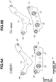
- FIG. 3 is a front view schematically showing the rear left wheel suspension system.
- FIG. 4 is an external view of a lower rear link shown in FIG. 2 .
- FIG. 5 shows a connect bush connecting the lower front and rear links.
- FIG. 5A is a top view of the connect bush.
- FIG. 5B is a longitudinal sectional view taken across a line A-B shown in FIG. 5A.
- FIG. 5C is a cross sectional view cut by a plane to which the axis is perpendicular.
- FIG. 5D is a perspective view of an inner cylinder of the connect bush, and
- FIG. 5E is a perspective view of an outer cylinder of the connect bush.
- FIG. 6 is a front view showing the connect bushes connected with the lower front link.
- FIG. 7 shows the construction of the lower front link.
- FIG. 7A is a perspective view of the lower front link
- FIG. 7B is a sectional view of the lower front link.
- FIG. 8 shows the connect bush connected with lower front link.
- FIG. 8A is a longitudinal sectional view of the connect bush
- FIG. 8B is an enlarged sectional view showing a forward end of the outer cylinder of the connect bush.
- FIG. 9 shows the lower front link and upper link in front elevation.
- FIG. 9A is a front view in the state of the standard vehicle body posture
- FIG. 9B is a front view in a full bound stroke state.
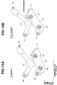
- FIG. 10 shows lower front link and upper link in a comparative example.
- FIG. 10A is a front view in the state of the standard vehicle body posture
- FIG. 10B is a front view in the full bound stroke state.
- FIG. 11 is a perspective view schematically showing the suspension system.
- FIG. 12 shows the positional relationship of the lower front link and a brake hose shown in FIG. 11 in the comparative example.
- FIG. 12A is a perspective view of the lower front link as viewed approximately from above
- FIG. 12B is a perspective view of the lower front link as viewed approximately from the front side.
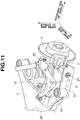
- FIG. 13 shows the positional relationship of the lower front link and the brake hose in the example according to the embodiment.
- FIG. 13A is a perspective view of the lower front link as viewed approximately from above
- FIG. 13B is a perspective view of the lower front link as viewed approximately from the front side.
- FIG. 14 shows a variation example 1 of the lower front link.
- FIG. 14A is a perspective view of the lower front link
- FIG. 14B is a sectional view.
- FIG. 15 shows a variation example 2 of the lower front link.
- FIG. 15A is a perspective view of the lower front link
- FIG. 15B is a sectional view.
- FIG. 16 a top view schematically showing a rear left wheel suspension system in a variation example according to the embodiment of the present invention.
- FIG. 1 is a perspective view schematically showing a rear wheel suspension system in perspective.
- FIG. 2 is schematic top view schematically showing a rear left wheel suspension system.
- FIG. 3 is a schematic front view schematically showing the rear left wheel suspension system.
- a rear left wheel independent suspension system or structure is taken as an example.
- the suspension system shown in FIGS. 2 and 3 connects a wheel 1 to a suspension member 2 (vehicle body member) of a vehicle body, and includes an axle housing 11 (hub carrier)(wheel support member), a lower front link 12 (front suspension link), a lower rear link 13 (rear suspension link), an upper link 14, a coil spring 15 and a strut 5 (shown in FIG. 1 ).
- Axle housing 11 is a wheel support member supporting the wheel 1 rotatably.
- the front and lower rear links 12 and 13 are arranged in a front and rear direction (of the suspension system) corresponding to the vehicle longitudinal direction, at approximately equal heights (in the vertical, or up and down, direction corresponding to the vehicle vertical direction).
- Lower front link 12 extends substantially or approximately in a transverse direction (of the suspension system)(corresponding to the vehicle widthwise or lateral direction) from an outboard end (on the outboard side remoter from the center line of the vehicle) to an inboard end (on the inboard side closer to the vehicle center line).
- the outboard end of lower front link 12 is connected, through a bush 21 (front outboard link bush), swingably with a lower front portion of the axle housing 11.
- the inboard end of lower front link 12 is connected, through a bush 22 (front inboard link bush), swingably with a lower front portion of the suspension member 2.
- a bush 22 front inboard link bush
- the connection point on the outboard side is located slightly on the rear side of the connection point on the inboard side (the position of bush 22) in the front and rear direction or in the vehicle longitudinal direction.
- Lower rear link 13 extends substantially in the transverse direction (corresponding to the vehicle lateral direction) from an outboard end (on the outboard side) to an inboard end (on the inboard side).
- the outboard end of lower rear link 13 is connected through a bush 23 (rear outboard link bush) swingably with a lower rear portion of the axle housing 11.
- the inboard end of lower rear link 13 is connected through a bush 24 (rear inboard link bush) swingably with a lower rear portion of the suspension member 2.
- the connection point on the outboard side (the position of bush 23) and the connection point on the inboard side (the position of bush 24) are located approximately at the same position in the front and rear direction corresponding to the vehicle longitudinal direction.
- the distance between the front outboard connection point (the position of bush 21) of lower front link 12 and the rear outboard connection point (the position of bush 23) of lower rear link 13 with respect to axle housing 11 is smaller than the distance between the front inboard connection point (the position of bush 22) of lower front link 12 and the rear inboard connection point (the position of bush 24) of lower rear link 13 with respect to suspension member 2.
- the straight line L1 (the axis or center line of lower front link 12) connecting the positions of outboard bush 21 and inboard bush 22 of lower front link 12 and the straight line L2 (the axis or center line of lower rear link 13) connecting the positions of outboard bush 23 and inboard bush 24 of lower rear link 13 intersect with each other at an intersection point located on the outboard side of the links 12 and 13 (or on the outboard side of the axle housing 11 or the wheel 1). As shown in FIG.
- the lower rear link 13 extends in the transverse direction or in the vehicle lateral direction whereas the lower front link 12 extends obliquely so that the distance or spacing between the lower front and rear links 1 2 and 13 in the front and rear direction or the vehicle longitudinal direction becomes gradually smaller in the outboard direction from the inboard ends to the outboard ends of lower front and rear links 12 and 13.
- Upper link 14 extends substantially in the transverse direction corresponding to the vehicle lateral direction, from an outboard end (on the outboard side) to an inboard end (on the inboard side) above the lower front and rear links 12 and 13.
- the outboard end of upper link 14 is connected through a bush 25 (upper outboard link bush) swingably with an upper portion of the axle housing 11.
- the inboard end of upper link 14 is connected through a bush 26 (upper inboard link bush) swingably with an upper portion of the suspension member 2.
- Each of the (link) bushes 21 ⁇ 26 includes an outer cylinder or tube, an inner cylinder or tube nested or inserted in the outer cylinder, and an elastic member made of resilient or elastic material such as rubber interposed radially between the outer and inner cylinders.
- all the bushes 21 ⁇ 26 for the lower front link 12, lower rear link 13 and upper link 14 are arranged so that the outer cylinder of each bush is connected with the corresponding end of the link 12, 13 or 14 and the inner cylinder of each bush is connected with the axle housing 11 or suspension member 2.
- Lower rear link 13 includes a projecting (plate-like) portion 16 (wing portion) projecting toward the lower front link 1 2.
- Projecting portion 16 is an integral part of lower rear link 13.
- Projecting portion 13 projects forwards in the front and rear direction corresponding to the vehicle longitudinal direction (from the line L2) to a front end.
- the front end of projecting portion 13 is connected with the lower front link 12 through at least one connect bush allowing predetermined relative displacement.
- the front end of projecting portion 13 is connected with the lower front link 12 through connect bushes 27 and 28 allowing predetermined relative displacement.
- the connect bushes 27 and 28 are arranged along lower front link 12.
- Each of connect bushes 27 and 28 includes an outer cylinder or tube, an inner cylinder or tube nested or inserted in the outer cylinder, and an elastic member made of resilient or elastic material such as rubber interposed radially between the outer and inner cylinders.
- the connect bushes 27 and 28 are arranged so that the axis of the bush extends substantially in the front and rear direction corresponding to the vehicle longitudinal direction, and the outer cylinder of each bush is connected with the lower front link 1 2 and the inner cylinder of each bush is connected with the projecting portion 16 of lower rear link 13.
- the lower rear link 13 including the projecting portion 1 6 is capable of displacing relative to lower front link 12 within a movable range (deflection range) of the connect bushes 27 and 28.
- each of the connect bushes 27 and 28 is anisotropic in stiffness or rigidity so that the stiffness in the transverse direction (the vehicle lateral direction) is lower than the stiffness in the vertical direction.
- Connect bushes 27 and 28 will be explained more in detail later.
- a toe control is performed at the time of braking in a following manner.
- the axle housing 11 is displaced rearwards to the rear of the vehicle body.
- a rearward displacement quantity of the connection point (bush 21) of lower front link 12 with respect to axle housing 11 and a rearward displacement quantity of the connection point (bush 23) of lower rear link 13 with respect to axle housing 11 are substantially equal to each other.
- an inboard displacement quantity of the connection point (bush 21) of lower front link 12 is greater than an inboard displacement quantity of the connection point (bush 23) of lower rear link 13 in the inboard lateral (or vehicle widthwise) direction toward the center line (longitudinal axis) of the vehicle body.
- the front connection point (bush 21) of axle housing 11 is pulled inwards in the inboard lateral direction toward the center line of the vehicle body, and hence a toe change is produced in wheel 1 during braking, in a direction to increase the quantity of toe-in, to the advantage of the stability.
- the coil spring 15 is arranged in a following manner.
- Coil spring 15 is disposed between lower rear link 13 and the vehicle body so that a coil axis XA is substantially vertical in the vertical direction.
- Coil spring 15 is located so as to overlap the straight line L2 as viewed in the plan view.
- the coil axis XA is located on straight line L2 as shown in FIG. 2 , or the coil axis XA intersects the straight line L2.
- the coil spring 15 is mounted on lower rear link 13 at a middle or about the middle between the rear outboard connection point (bush 23) and the rear inboard connection point (bush 24).
- a seating surface of coil spring 15 extends and overlaps the projecting portion 1 6 of lower rear link 13.
- Lower rear link 13 includes a rear portion projects rearwards so as to conform with the outside diameter of coil spring 15.
- FIG. 4 is an external view of the lower rear link 13, for showing an assembly structure of lower rear link 13 and coil spring 15.
- a lower spring seat 17 is interposed between the lower end of coil spring 15 and lower rear link 13.
- the lower spring seat 17 having an annular shape is installed in the lower rear link 13, and the lower end of coil spring 1 5 is attached to this lower spring seat 17.
- Lower rear link 13 has a hollow structure made up of a lower bracket 31 and an upper bracket 32 which are shaped in a recessed form like a dish or a pan, and which are joined so that the concave sides of the lower and upper brackets 31 and 32 confront each other.
- Lower and upper brackets 31 and 32 are joined together and united by arc welding.
- a curved portion 18 is formed in lower rear link 13.
- Curved portion 18 is a portion where the cross sectional area is varied sharply from the connection point (bush 24) with suspension member 2, to the inboard connection point (bush 28) with lower front link 12.
- a reinforcing bracket 19 is attached to the curved portion 18. Reinforcing bracket 19 is arranged to straddle and hold (or clamp) the lower bracket 31 and upper bracket 32. Lower rear link 13 and reinforcing bracket 19 are joined together and united by arc welding.
- Lower spring seat 1 7 is disposed on a concave surface (inside bottom surface) of lower bracket 31.
- Coil spring 15 extends from the lower end attached to this lower spring seat 1 7, through an opening formed in upper bracket 32, and projects upwards.
- FIG. 5 shows the connect bush in a single state.
- FIG. 5A is a top view of connect bush 27.
- FIG. 5B is a longitudinal sectional view taken across a line A-B shown in FIG. 5A.
- FIG. 5C is a cross sectional view cut by a plane to which the axis is perpendicular.
- FIG. 5D is a perspective view of an inner cylinder 71
- FIG. 5E is a perspective view of an outer cylinder 81.
- Connect bush 27 includes an inner cylinder (or tube) 71 having an axis extending substantially in the vehicle front and rear (or longitudinal) direction, an outer cylinder (or tube) 81 surrounding the inner cylinder 71, and an elastic member 91 interposed (radially) between the inner and outer cylinders 71 and 81.
- Inner cylinder 71 is connected with the extending portion 16 of lower rear link 13
- outer cylinder 81 is connected with lower front link 12.
- the inner and outer cylinders 71 and 81 are arranged coaxially (substantially on the same axis).
- An outside circumferential (or cylindrical) surface 72 of inner cylinder 71 confronts (radially) an inside circumferential (or cylindrical) surface 82 of outer cylinder 81.
- Outer cylinder 81 includes a pair of convex portions 83 projecting radially inwards toward the outside circumferential surface 72 of inner cylinder 71, respectively from two positions (diametrically opposite circumferential positions) spaced from each other in the vertical direction (R) (corresponding to the vehicle up and down direction) on the inside circumferential surface 82 of outer cylinder 81.
- the convex portion 83 are formed at a middle or in a central portion between the two axial ends of outer cylinder 81 extending in the P direction, and the convex portion 83 extends circumferentially approximately in the side direction (Q) (corresponding to the vehicle widthwise lateral direction), in the form of streak like a ridge.
- Convex portions 83 are formed by deforming the outer circumferential or cylindrical surface 84 of outer cylinder 81 into a concave form recessed in the vertical direction R (vehicle vertical direction), radially inwards toward the inner cylinder 71. That is, the convex portions 83 are formed by compressing the outer cylinder 81 in the vertical direction R, from both of the diametrically opposite radial outer sides to form compressed portion or concave grooves 85 extending circumferentially like a circular arc and being recessed radially inwards.
- the elastic member 91 is formed with thin wall portions 92 and thick wall portions 93.
- the thin wall portions 92 are spaced in the vertical direction R at upper and lower (diametrically opposite) positions, and deformed to have a thinner wall thickness.
- the thick wall portions 93 are spaced in the side (horizontal) direction (Q) at (outboard and inboard) (diametrically opposite) positions, and formed to have a thicker wall thickness greater than the thinner wall thickness of the thin wall portions 92. Therefore, in the compressive deformation in the diametrical direction perpendicular to the axis, the stiffness or rigidity of the thin wall portions 92 is made higher than the stiffness of thick wall portions 93.
- the connect bush 27 is stiff (higher elastic force) in the vertical direction R ( ⁇ the vehicle vertical direction), and soft (lower elastic force) in the side direction (Q) ( ⁇ the vehicle lateral direction).
- the connect bush 27 serves as a stiff spring in the vehicle up and down direction and serves as a soft spring in the vehicle lateral direction.
- Convex portions 83 is formed in outer cylinder 81 after the elastic member 91 is formed by vulcanization or curing between inner and outer cylinders 71 and 81.
- the portions of elastic member 91 between the outside circumferential surface 72 of inner cylinder 71 and the convex portions 83 of outer cylinder 81 are made dense to have a higher density as compared to the remaining portion, and hence the stiffness in the vertical direction R ( ⁇ vehicle up and down or vertical direction) is further increased.
- Elastic member 91 extends axially (in the direction P) from one of two axial end surfaces 94 to the other, and each of the axial end surfaces 94 is formed with two hollow portions (or relief portions) 95 (circumferential grooves) at two diametrically opposite positions in the side direction (Q) (substantially identical to the vehicle lateral direction).
- Each of the hollow portions 95 is in the form of a circumferential groove 95 depressed in the axial direction and extended in the circumferential direction around the axis of elastic ember 91.
- the circumferential grooves 95 are not so deep as to pierce the elastic member 95. With the circumferential grooves 95, the stiffness of elastic member 91 is decreased in the side direction (Q) corresponding to the vehicle lateral direction.
- Inner cylinder 71 includes cut surfaces 73 formed in the outside circumferential surface 72 at two diametrically opposite positions spaced in the side direction (Q) (vehicle lateral direction).
- the cut surfaces 73 are substantially in the form of two parallel flat planes extending substantially in parallel to the vertical direction R. Cut surfaces 73 extend axially from one of the axial ends of inner cylinder 71, and terminate without reaching the other axial end of inner cylinder 71. With these cut surfaces 73, the radial thickness (the thickness in the radial thickness) of inner cylinder 71 measured in the vertical direction R is smaller than the radial thickness of inner cylinder 71 measured in the side direction (Q) (vehicle lateral direction).
- the radial thickness of elastic member 91 is increased in the side direction (Q) (vehicle lateral direction) with the outer cylinder 81 having the inside diameter being set constant, and the stiffness of elastic member 91 is decreased in the side direction (Q) (vehicle lateral direction) as compared to a bush structure having no cut surfaces 73.
- the stiffness in the vertical direction R is adjusted by adjusting the radial thickness, the axial width and/or the circumferential length of thin wall portion or portions 92 in elastic member 91 , and/or by adjusting the amount of projection, the axial width and/or the length in the side direction (Q), of the convex portion or portions 83.
- the two convex portions 83 are to be formed at positions shifted from the positions of the two grooves 95 by 90 degrees in phase.
- Two grooves 95 and two cut surfaces 73 are arranged in the same angular direction. Therefore, the two convex portion 83 can be formed at the angular position rotated by 90 degrees with respect to the cut surfaces 73.
- the connect bush 27 (or 28) is set in a jig (not shown) with reference to the cut surfaces 73.
- the cut surfaces 73 are used as means for positioning the connect bush with respect to the jig in the production process of the connect bush.
- FIG. 6 is a front view showing the connect bushes 27 and 28 connected with lower front link 12.
- the straight line L1 connecting the outboard connection point (bush 21) and the inboard connection point (bush 22) of lower front link 12 extends approximately in the vehicle lateral or widthwise direction (horizontal direction).
- the lower front link 1 2 is in the form a long rectangle extending horizontally.
- lower front link 12 includes a lower portion extending below the straight line L1 connecting the outboard connection point (bush 21) and the inboard connection point (bush 22) of lower front link 1 2.
- Connect bushes 27 and 28 are disposed at a level lower by a vertical distance or level difference ⁇ H than the level of the outboard connection point (bush 21) of lower front link 12. As best shown in FIG. 6 , connect bushes 27 and 28 are located at the level which is lower than the straight line L1 connecting the outboard connection point (bush 21) and the inboard connection point (bush 22) of lower front link 1 2, by vertical distance ⁇ H.
- a straight line L3 connecting the connect bushes 27 and 28 with each other is substantially parallel to the straight line L1 connecting the outboard connection point (bush 21) and the inboard connection point (bush 22) of lower front link 1 2. Line L3 extends along line L1, on the lower side of line L1.
- Each of connect bushes 27 and 28 is installed so that a first perpendicular (or radial) direction R perpendicular to the bush axis is a vertical or up-and-down direction, and a second perpendicular (or radial) direction Q perpendicular to the axis and perpendicular to the first perpendicular direction R is a side direction (or horizontal direction).
- the hollow portions 95 confront each other in the second perpendicular direction or side direction Q
- the convex portion 83 (concave portions 85) confront each other in the first perpendicular direction or vertical direction R.
- each of connect bushes 27 and 28 is so oriented that the vertical direction R of the bush extends approximately in the vehicle vertical direction and the side direction Q of the bush extends approximately in the vehicle lateral or widthwise direction.
- the side direction Q of inboard connect bush 28 is set in the vehicle lateral direction whereas the side direction Q of outboard connect bush 27 is inclined by a predetermined angle ⁇ with respect to the vehicle lateral direction.
- the side direction Q of outboard connect bush 27 is rotated in the counterclockwise direction by the predetermined angle ⁇ which is equal to 30 degrees in this example.
- FIG. 7 shows the construction of the lower front link.
- FIG. 7A is a perspective view of lower front link 12
- FIG. 7B is a sectional view of lower front link 12.
- Lower front link 12 has a hollow structure formed by a lower bracket 31 having a U-shaped section opening upwards, and an upper bracket 32 closing an upper portion of lower bracket 31.
- FIG. 8 shows, in section, the connect bush connected with lower front link 1 2.
- FIG. 8A is a longitudinal sectional view of connect bush 27, and
- FIG. 8B is an enlarged sectional view showing a forward end 86 of outer cylinder 81 in a press fitting direction.
- Connect bush 27 is inserted forcibly into the lower front link 12 from the rear side (of the vehicle).
- the outer cylinder 81 of connect bush 27 is forcibly fit in an engagement hole 29 of lower front link 12 from the rear side.
- the forward end 86 of outer cylinder 81 leading in the press-fitting direction is slightly bent radially inwards or slightly tapered and used as a guide for assisting insertion of connect bush 27 into the engagement hole 29 of lower front link 12.
- FIG. 9 shows the lower front link and upper link in front elevation.
- FIG. 9A is a front view in the state of the standard vehicle body posture
- FIG. 9B is a front view in a full bound stroke state.
- the upper link 14 extends from an inboard end to an outboard end curvedly so that a central portion is bent downwards and an upper end is curved in a concave form so as to avoid interference with a side member (not shown) of the vehicle body extending above upper link 14. Therefore, the central portion of upper link 14 between the inboard and outboard ends is close to the lower front link 12.
- the upper link 14 could interfere with the lower front link 12 in dependence on the positions and shapes of both links 14 and 12, and might limit the suspension stroke quantity undesirably.
- the connect bushes 27 and 28 are located below the outboard connection point (bush 21) of lower front link 12, as shown in FIG. 6 .
- connect bushes 27 and 28 are located below the (imaginary) straight line L1 connecting (the axis of) bush 21 and (the axis of) bush 22.
- the lower front link 1 2 can be made in the form including a larger lower portion extending downwards in the widthwise direction of lower front link 12, below the imaginary line L1 and a smaller upper portion which projects upwards only slightly above line L1. Therefore, this arrangement can avoid interference between lower front link 12 and upper link 14 even in the full bound stroke state as shown in FIG. 9B , and ensure a sufficient amount of the suspension stroke.
- FIG. 10 shows a comparative example.
- FIG. 10A is a front view in the state of the standard vehicle body posture
- FIG. 10B is a front view in the full bound stroke state.
- This comparative example employs a lower front link 20 having a shape different from the shape of lower front link 1 2, whereas the upper link 14 of the comparative example is identical in shape to the upper link of FIG. 9 .
- the outboard connect bush 27 is disposed above the outboard connection point (bush 21) of lower front link 20.
- Inboard connect bush 28 is located below the inboard connection point (bush 22) of lower front link 20.
- the lower front link 20 of the comparative example is so shaped as to project upwards. Consequently, the lower front link 20 might interfere with upper link 14 in the full bound stroke state as shown in. FIG. 10B . To avoid the interference, the stroke is limited in a narrower range.
- FIG. 11 shows the suspension system schematically in perspective, to show a relationship between lower front link 1 2 and a brake hose.
- a brake caliper 4 for applying a braking force to a disc rotor 3 is connected through a brake hose 5, with a hydraulic circuit.
- the brake hose 5 is extended in the U-shaped form having upper segments located on an upper side of the lower front link 1 2 and a U-shaped lower segment located on a front side of lower front link 12.
- FIG. 12 shows the positional relationship of the lower front link and the brake hose in the comparative example.
- FIG. 1 2A is a perspective view of the lower front link 20 as viewed approximately from above
- FIG. 1 2B is a perspective view of the lower front link 20 as viewed approximately from the front side.
- the lower front link 20 has the upper portion bulging upwards, and therefore, the connect bush 27 might interfere with the brake hose 4 during a suspension stroke movement.
- FIG. 13 shows the positional relationship of the lower front link and the brake hose in the example according to the embodiment.
- FIG. 13A is a perspective view of the lower front link 12 as viewed approximately from above
- FIG. 13B is a perspective view of the lower front link 1 2 as viewed approximately from the front side.
- this suspension structure can avoid interference between the connect bush 27 and brake hose 4 during a suspension stroke movement.
- the suspension structure functions in the following manner.
- the line L3 connecting the connect bushes 27 and 28 is located below the line L1 connecting the link bushes 21 and 22. Therefore, by shifting the line L3 connecting the connect bushes 27 and 28 closer to the tire ground contact point, the suspension structure can increase the lateral stiffness of the suspension structure because of the relationship of a couple of forces.
- the suspension structure functions in the following manner.
- the second perpendicular direction Q of connect bush 27 is so set as to extend in the vehicle lateral direction.
- the connect bush 27 is located below the level of the outboard connection point (bush 21). Accordingly, it is not easy to secure a toe-in change of wheel 1 in response to a longitudinal force input during braking. Therefore, in the illustrated example of the embodiment, the second perpendicular direction Q of connect bush 27 is displaced by a predetermined angle ( ⁇ 30°) with respect to the vehicle lateral direction (with respect to the line L1 or the line L3). With this arrangement, the suspension structure can secure the toe-in change of an amount comparable to the toe-in change in the comparative example, and thereby improve the stability. It is possible to change the shape, the position and the number of each of component parts within the purview of the present invention. In this embodiment, at least one of connect bushes 27 and 28 corresponds to "bush".
- the connect bush (27, 28) is located below the level of the front outboard connection point (bush 21) of the lower front link (12). Therefore, the lower front link can be made in the form including a larger lower portion extending downwards and a smaller upper portion which projects upwards only slightly. Therefore, this arrangement can avoid interference between lower front link 1 2 and upper link 14, and ensure a sufficient amount of the suspension stroke.
- the connect bush (27, 28) is located below the (imaginary) straight line (L1) connecting the (front outboard) connection point (21) and the (front inboard) connection point (22). Therefore, the lower front link 12 can be made in the form including a larger lower portion extending downwards and a smaller upper portion which projects upwards only slightly. Therefore, this arrangement can avoid interference between lower front link 12 and upper link 14, and ensure a sufficient amount of the suspension stroke.
- the lower front and rear links (1 2, 1 3) are connected by two of the connect bushes (27, 28), one being an inboard connect bush (28) and the other being an outboard connect bush (27) located on an outboard side of the inboard connect bush, and the inboard and outboard connect bushes (28, 27) are so arranged that the (imaginary) straight line (L3) connecting the position of the inboard connect bush (28) and the position of the outboard connect bush (27) is parallel to the straight line (L1) connecting the connection point between the lower front link and the wheel support member and the connection point between the lower front link and the vehicle body member in a front view of the vehicle body.
- the suspension structure can increase the lateral stiffness of the suspension.
- the connect bush (27, 28) is so configured that the stiffness of the connect bush in a first perpendicular direction R perpendicular to the axis of the connect bush is lower than the stiffness of the connect bush in a second perpendicular direction Q perpendicular to the axis of the connect bush and perpendicular to the first perpendicular direction R.
- the connect bush or at least one of the connect bushes is disposed so that the second perpendicular direction Q of the connect bush is inclined with respect to the vehicle lateral direction by a predetermined angle ( ⁇ )( ⁇ 30°, for example) in a standard vehicle body posture (having no suspension stroke). Therefore, the suspension structure can cause a toe-in change in the wheel 1 in the case of input of a longitudinal force due to braking, and thereby improve the stability during braking.
- the connect bush (27, 28) is located below the level of the front outboard connection point (bush 21) of the lower front link (12). Therefore, the lower front link 12 can be made in the form including a larger lower portion extending downwards and a smaller upper portion which projects upwards only slightly. Therefore, this arrangement can avoid interference between lower front link 12 and upper link 14, and ensure a sufficient amount of the suspension stroke.
- the inner cylinder 71 is connected with the projecting or extending portion 16 of lower rear link 13, and the outer cylinder 81 is connected with lower front link 12.
- outer cylinder 81 is connected with the projecting portion 16 of lower rear link 13
- the inner cylinder 71 is connected with lower front link 12. This arrangement, too, can provide the same effects and operations.
- the lower front link 12 is in the form of a hollow structure formed by closing the upper end of lower bracket 31 with upper bracket 32. However, it is optional to employ the lower front link 12 having a different structure.
- FIG. 14 shows a variation example 1 of the lower front link 12.
- FIG. 14A is a perspective view of lower front link 12
- FIG. 14B is a sectional view.
- the lower front link 12 of this example has a hollow structure formed by joining a front bracket 33 and a rear bracket 34. Front and rear brackets 33 and 34 confront each other and extend side by side in the longitudinal direction of lower front link 12 from the inboard end to the outboard end. This example too can provide the same effects and operation as in the illustrated example of the embodiment.
- FIG. 15 shows a variation example 2 of the lower front link 12.
- FIG. 15A is a perspective view of lower front link 12
- FIG. 15B is a sectional view.
- the lower front link 12 has a hollow structure having a rectangular cross section, formed by hydroforming. This example too can provide the same effects and operation as in the illustrated example of the embodiment.
- a suspension system or structure has a basic structure comprising: lower front and rear links arranged to connect a wheel support member adapted to support a wheel and a vehicle body member swingably; an upper link located above the lower front link and arranged to connect the wheel support member and the vehicle body swingably; and a connect bush arranged to connect the lower front link and the lower rear link with each other, the connect bush being located below (the level of) a (front outboard) connection point between the lower front link and the wheel support member.
- the suspension system may further comprise any one or more of the following features (F1) ⁇ (F7).
- the connect bush is located below a (imaginary) straight line connecting the connection point between the lower front link and the wheel support member and a connection point between the lower front link and the vehicle body member.
- the suspension structure comprises two of the connect bushes, one being an inboard connect bush and the other being an outboard connect bush located on an outboard side of the inboard connect bush, the inboard and outboard connect bushes are both located below a (imaginary) straight line connecting the connection point between the lower front link and the wheel support member and a connection point between the lower front link and the vehicle body member.
- the inboard and outboard connect bushes are so arranged that a (imaginary) straight line connecting the position (of the axis) of the inboard connect bush and the position (of the axis) of the outboard connect bush is parallel to the (imaginary) straight line connecting the connection point between the lower front link and the wheel support member and the connection point between the lower front link and the vehicle body member.
- the connect bush (27, 28) (or each connect bush or at least one of the connect bushes) includes: an inner cylinder (71) which extends in an axial direction (P) of the connect bush (the axial direction (P) is perpendicular to a link longitudinal direction (L1, L2) of one (12) of the front and rear suspension links (12, 13), for example), from a rear end to a front end located on the front side of the rear end of the inner cylinder in a front and rear direction (corresponding to the vehicle longitudinal direction) and which is connected with one (13) of the lower front and rear links (12, 13), an outer cylinder (81) which includes an inside circumferential surface confronting (radially) an outside circumferential surface of the inner cylinder and which is connected with the other of the lower front and rear links, and an elastic member interposed between the inner cylinder and the outer cylinder, the elastic member being so configured that a stiffness of the elastic member in a first perpendicular direction R (vertical direction) perpendicular to an axis of the connect bush
- the connect bush is disposed so that the second perpendicular direction Q of the connect bush is inclined with respect to the vehicle lateral direction by a predetermined angle ( ⁇ ) in a standard vehicle body posture (having no suspension stroke).
- the connect bush is disposed so that the first perpendicular direction R of the connect bush is inclined with respect to a vertical direction by a predetermined angle ( ⁇ ) (or the connect bush is disposed so that the second perpendicular direction Q of the connect bush is inclined, by a predetermined angle ( ⁇ ), with respect to a (imaginary) straight line (L1) connecting the (front outboard) connection point (21) between the lower front link (12) and the wheel support member (11) and a (front inboard) connection point (22) between the lower front link (12) and the vehicle body member (2))
- the suspension structure comprises two of the connect bushes, one being an inboard connect bush and the other being an outboard connect bush located on an outboard side of the inboard connect bush; and the outboard and inboard connect bushes are so arranged that the
Landscapes
- Engineering & Computer Science (AREA)
- Mechanical Engineering (AREA)
- Vehicle Body Suspensions (AREA)
Abstract

Description
- The present invention relates to suspension structure and/or suspension link arranging method.
- In a suspension system as disclosed in
JP2009-214743A - In the suspension system as disclosed in the above-mentioned patent document, the upper link has a shape bent downwards to avoid interference with a side member of the vehicle body located above the upper link. Therefore, the upper link might interfere with the lower link, and hence makes it difficult to secure a sufficient amount of the suspension stroke.
Therefore, it is an object of the present invention to restrain interference between suspension links and secure a sufficient amount of the suspension stroke. - According to the present invention, a suspension structure comprises: lower front and rear links arranged to connect a wheel support member adapted to support a wheel and a vehicle body member swingably; an upper link located above the lower front link and arranged to connect the wheel support member and the vehicle body swingably; and a connect bush arranged to connect the lower front link and the lower rear link with each other, the connect bush being located below a connection point between the lower front link and the wheel support member.
-
FIG. 1 is a perspective view schematically showing a rear wheel suspension system according to one embodiment of the present invention. -
FIG. 2 is a top view schematically showing a rear left wheel suspension system. -
FIG. 3 is a front view schematically showing the rear left wheel suspension system. -
FIG. 4 is an external view of a lower rear link shown inFIG. 2 . -
FIG. 5 shows a connect bush connecting the lower front and rear links.FIG. 5A is a top view of the connect bush.FIG. 5B is a longitudinal sectional view taken across a line A-B shown inFIG. 5A. FIG. 5C is a cross sectional view cut by a plane to which the axis is perpendicular.FIG. 5D is a perspective view of an inner cylinder of the connect bush, andFIG. 5E is a perspective view of an outer cylinder of the connect bush. -
FIG. 6 is a front view showing the connect bushes connected with the lower front link. -
FIG. 7 shows the construction of the lower front link.FIG. 7A is a perspective view of the lower front link, andFIG. 7B is a sectional view of the lower front link. -
FIG. 8 shows the connect bush connected with lower front link.FIG. 8A is a longitudinal sectional view of the connect bush, andFIG. 8B is an enlarged sectional view showing a forward end of the outer cylinder of the connect bush. -
FIG. 9 shows the lower front link and upper link in front elevation.FIG. 9A is a front view in the state of the standard vehicle body posture, andFIG. 9B is a front view in a full bound stroke state. -
FIG. 10 shows lower front link and upper link in a comparative example.FIG. 10A is a front view in the state of the standard vehicle body posture, andFIG. 10B is a front view in the full bound stroke state. -
FIG. 11 is a perspective view schematically showing the suspension system. -
FIG. 12 shows the positional relationship of the lower front link and a brake hose shown inFIG. 11 in the comparative example.FIG. 12A is a perspective view of the lower front link as viewed approximately from above, andFIG. 12B is a perspective view of the lower front link as viewed approximately from the front side. -
FIG. 13 shows the positional relationship of the lower front link and the brake hose in the example according to the embodiment.FIG. 13A is a perspective view of the lower front link as viewed approximately from above, andFIG. 13B is a perspective view of the lower front link as viewed approximately from the front side. -
FIG. 14 shows a variation example 1 of the lower front link.FIG. 14A is a perspective view of the lower front link, andFIG. 14B is a sectional view. -
FIG. 15 shows a variation example 2 of the lower front link.FIG. 15A is a perspective view of the lower front link, andFIG. 15B is a sectional view. -
FIG. 16 a top view schematically showing a rear left wheel suspension system in a variation example according to the embodiment of the present invention. - The following is explanation on a vehicle such as motor vehicle according to an embodiment of the present invention, with reference to drawings.
FIG. 1 is a perspective view schematically showing a rear wheel suspension system in perspective.FIG. 2 is schematic top view schematically showing a rear left wheel suspension system.FIG. 3 is a schematic front view schematically showing the rear left wheel suspension system. - In the illustrated example of this embodiment, a rear left wheel independent suspension system or structure is taken as an example. The suspension system shown in
FIGS. 2 and3 connects awheel 1 to a suspension member 2 (vehicle body member) of a vehicle body, and includes an axle housing 11 (hub carrier)(wheel support member), a lower front link 12 (front suspension link), a lower rear link 13 (rear suspension link), anupper link 14, acoil spring 15 and a strut 5 (shown inFIG. 1 ).Axle housing 11 is a wheel support member supporting thewheel 1 rotatably. - The front and lower
rear links front link 12 extends substantially or approximately in a transverse direction (of the suspension system)(corresponding to the vehicle widthwise or lateral direction) from an outboard end (on the outboard side remoter from the center line of the vehicle) to an inboard end (on the inboard side closer to the vehicle center line). The outboard end of lowerfront link 12 is connected, through a bush 21 (front outboard link bush), swingably with a lower front portion of theaxle housing 11. The inboard end of lowerfront link 12 is connected, through a bush 22 (front inboard link bush), swingably with a lower front portion of thesuspension member 2. In the plan view (as shown inFIG. 2 ), the connection point on the outboard side (the position of bush 21) is located slightly on the rear side of the connection point on the inboard side (the position of bush 22) in the front and rear direction or in the vehicle longitudinal direction. - Lower
rear link 13 extends substantially in the transverse direction (corresponding to the vehicle lateral direction) from an outboard end (on the outboard side) to an inboard end (on the inboard side). The outboard end of lowerrear link 13 is connected through a bush 23 (rear outboard link bush) swingably with a lower rear portion of theaxle housing 11. The inboard end of lowerrear link 13 is connected through a bush 24 (rear inboard link bush) swingably with a lower rear portion of thesuspension member 2. In the plan view (as shown inFIG. 2 ), the connection point on the outboard side (the position of bush 23) and the connection point on the inboard side (the position of bush 24) are located approximately at the same position in the front and rear direction corresponding to the vehicle longitudinal direction. - The distance between the front outboard connection point (the position of bush 21) of lower
front link 12 and the rear outboard connection point (the position of bush 23) of lowerrear link 13 with respect toaxle housing 11 is smaller than the distance between the front inboard connection point (the position of bush 22) of lowerfront link 12 and the rear inboard connection point (the position of bush 24) of lowerrear link 13 with respect tosuspension member 2. Therefore, the straight line L1 (the axis or center line of lower front link 12) connecting the positions ofoutboard bush 21 andinboard bush 22 of lowerfront link 12 and the straight line L2 (the axis or center line of lower rear link 13) connecting the positions ofoutboard bush 23 andinboard bush 24 of lowerrear link 13 intersect with each other at an intersection point located on the outboard side of thelinks 12 and 13 (or on the outboard side of theaxle housing 11 or the wheel 1). As shown inFIG. 2 , the lowerrear link 13 extends in the transverse direction or in the vehicle lateral direction whereas thelower front link 12 extends obliquely so that the distance or spacing between the lower front andrear links 1 2 and 13 in the front and rear direction or the vehicle longitudinal direction becomes gradually smaller in the outboard direction from the inboard ends to the outboard ends of lower front andrear links -
Upper link 14 extends substantially in the transverse direction corresponding to the vehicle lateral direction, from an outboard end (on the outboard side) to an inboard end (on the inboard side) above the lower front andrear links upper link 14 is connected through a bush 25 (upper outboard link bush) swingably with an upper portion of theaxle housing 11. The inboard end ofupper link 14 is connected through a bush 26 (upper inboard link bush) swingably with an upper portion of thesuspension member 2. - Each of the (link)
bushes 21∼26 includes an outer cylinder or tube, an inner cylinder or tube nested or inserted in the outer cylinder, and an elastic member made of resilient or elastic material such as rubber interposed radially between the outer and inner cylinders. In this example, all thebushes 21∼26 for thelower front link 12, lowerrear link 13 andupper link 14 are arranged so that the outer cylinder of each bush is connected with the corresponding end of thelink axle housing 11 orsuspension member 2. - Lower
rear link 13 includes a projecting (plate-like) portion 16 (wing portion) projecting toward the lowerfront link 1 2. Projectingportion 16 is an integral part of lowerrear link 13. Projectingportion 13 projects forwards in the front and rear direction corresponding to the vehicle longitudinal direction (from the line L2) to a front end. The front end of projectingportion 13 is connected with thelower front link 12 through at least one connect bush allowing predetermined relative displacement. In this example, the front end of projectingportion 13 is connected with thelower front link 12 throughconnect bushes connect bushes front link 12. Each ofconnect bushes connect bushes front link 1 2 and the inner cylinder of each bush is connected with the projectingportion 16 of lowerrear link 13. - The lower
rear link 13 including the projectingportion 1 6 is capable of displacing relative to lowerfront link 12 within a movable range (deflection range) of theconnect bushes connect bushes Connect bushes - A toe control is performed at the time of braking in a following manner.
When a rearward force toward the rear of the vehicle body is inputted towheel 1 by a braking operation or other factors, theaxle housing 11 is displaced rearwards to the rear of the vehicle body. In this case, a rearward displacement quantity of the connection point (bush 21) of lowerfront link 12 with respect toaxle housing 11 and a rearward displacement quantity of the connection point (bush 23) of lowerrear link 13 with respect toaxle housing 11 are substantially equal to each other. However, in the nonparallel arrangement or geometry of straight lines L1 and L2 as mentioned before, an inboard displacement quantity of the connection point (bush 21) of lowerfront link 12 is greater than an inboard displacement quantity of the connection point (bush 23) of lowerrear link 13 in the inboard lateral (or vehicle widthwise) direction toward the center line (longitudinal axis) of the vehicle body. Thus, the front connection point (bush 21) ofaxle housing 11 is pulled inwards in the inboard lateral direction toward the center line of the vehicle body, and hence a toe change is produced inwheel 1 during braking, in a direction to increase the quantity of toe-in, to the advantage of the stability. - The
coil spring 15 is arranged in a following manner.Coil spring 15 is disposed between lowerrear link 13 and the vehicle body so that a coil axis XA is substantially vertical in the vertical direction.Coil spring 15 is located so as to overlap the straight line L2 as viewed in the plan view. Preferably, the coil axis XA is located on straight line L2 as shown inFIG. 2 , or the coil axis XA intersects the straight line L2. In this example, thecoil spring 15 is mounted on lowerrear link 13 at a middle or about the middle between the rear outboard connection point (bush 23) and the rear inboard connection point (bush 24). A seating surface ofcoil spring 15 extends and overlaps the projectingportion 1 6 of lowerrear link 13. Lowerrear link 13 includes a rear portion projects rearwards so as to conform with the outside diameter ofcoil spring 15. -
Coil spring 15 is connected with lowerrear link 13 in a following manner.FIG. 4 is an external view of the lowerrear link 13, for showing an assembly structure of lowerrear link 13 andcoil spring 15. Alower spring seat 17 is interposed between the lower end ofcoil spring 15 and lowerrear link 13. Thelower spring seat 17 having an annular shape is installed in the lowerrear link 13, and the lower end ofcoil spring 1 5 is attached to thislower spring seat 17. - Lower
rear link 13 has a hollow structure made up of alower bracket 31 and anupper bracket 32 which are shaped in a recessed form like a dish or a pan, and which are joined so that the concave sides of the lower andupper brackets upper brackets - A
curved portion 18 is formed in lowerrear link 13.Curved portion 18 is a portion where the cross sectional area is varied sharply from the connection point (bush 24) withsuspension member 2, to the inboard connection point (bush 28) with lowerfront link 12. A reinforcingbracket 19 is attached to thecurved portion 18. Reinforcingbracket 19 is arranged to straddle and hold (or clamp) thelower bracket 31 andupper bracket 32. Lowerrear link 13 and reinforcingbracket 19 are joined together and united by arc welding. -
Lower spring seat 1 7 is disposed on a concave surface (inside bottom surface) oflower bracket 31.Coil spring 15 extends from the lower end attached to thislower spring seat 1 7, through an opening formed inupper bracket 32, and projects upwards. -
Connect bushes Connect bushes bush 27 only.FIG. 5 shows the connect bush in a single state.FIG. 5A is a top view ofconnect bush 27.FIG. 5B is a longitudinal sectional view taken across a line A-B shown inFIG. 5A. FIG. 5C is a cross sectional view cut by a plane to which the axis is perpendicular.FIG. 5D is a perspective view of aninner cylinder 71 , andFIG. 5E is a perspective view of anouter cylinder 81. Connectbush 27 includes an inner cylinder (or tube) 71 having an axis extending substantially in the vehicle front and rear (or longitudinal) direction, an outer cylinder (or tube) 81 surrounding theinner cylinder 71, and anelastic member 91 interposed (radially) between the inner andouter cylinders Inner cylinder 71 is connected with the extendingportion 16 of lowerrear link 13, andouter cylinder 81 is connected with lowerfront link 12. - The inner and
outer cylinders inner cylinder 71 confronts (radially) an inside circumferential (or cylindrical) surface 82 ofouter cylinder 81.Outer cylinder 81 includes a pair ofconvex portions 83 projecting radially inwards toward theoutside circumferential surface 72 ofinner cylinder 71, respectively from two positions (diametrically opposite circumferential positions) spaced from each other in the vertical direction (R) (corresponding to the vehicle up and down direction) on the insidecircumferential surface 82 ofouter cylinder 81. Theconvex portion 83 are formed at a middle or in a central portion between the two axial ends ofouter cylinder 81 extending in the P direction, and theconvex portion 83 extends circumferentially approximately in the side direction (Q) (corresponding to the vehicle widthwise lateral direction), in the form of streak like a ridge. -
Convex portions 83 are formed by deforming the outer circumferential orcylindrical surface 84 ofouter cylinder 81 into a concave form recessed in the vertical direction R (vehicle vertical direction), radially inwards toward theinner cylinder 71. That is, theconvex portions 83 are formed by compressing theouter cylinder 81 in the vertical direction R, from both of the diametrically opposite radial outer sides to form compressed portion orconcave grooves 85 extending circumferentially like a circular arc and being recessed radially inwards. - With the
convex portions 83 ofouter cylinder 81 , theelastic member 91 is formed withthin wall portions 92 andthick wall portions 93. Thethin wall portions 92 are spaced in the vertical direction R at upper and lower (diametrically opposite) positions, and deformed to have a thinner wall thickness. Thethick wall portions 93 are spaced in the side (horizontal) direction (Q) at (outboard and inboard) (diametrically opposite) positions, and formed to have a thicker wall thickness greater than the thinner wall thickness of thethin wall portions 92. Therefore, in the compressive deformation in the diametrical direction perpendicular to the axis, the stiffness or rigidity of thethin wall portions 92 is made higher than the stiffness ofthick wall portions 93. In other words, theconnect bush 27 is stiff (higher elastic force) in the vertical direction R (≈the vehicle vertical direction), and soft (lower elastic force) in the side direction (Q) (≈the vehicle lateral direction). Thus, theconnect bush 27 serves as a stiff spring in the vehicle up and down direction and serves as a soft spring in the vehicle lateral direction. -
Convex portions 83 is formed inouter cylinder 81 after theelastic member 91 is formed by vulcanization or curing between inner andouter cylinders convex portions 83 in the insidecircumferential surface 82 ofouter cylinder 81 after the formation ofelastic member 91, the portions ofelastic member 91 between theoutside circumferential surface 72 ofinner cylinder 71 and theconvex portions 83 ofouter cylinder 81 are made dense to have a higher density as compared to the remaining portion, and hence the stiffness in the vertical direction R (≈vehicle up and down or vertical direction) is further increased. -
Elastic member 91 extends axially (in the direction P) from one of two axial end surfaces 94 to the other, and each of the axial end surfaces 94 is formed with two hollow portions (or relief portions) 95 (circumferential grooves) at two diametrically opposite positions in the side direction (Q) (substantially identical to the vehicle lateral direction). Each of thehollow portions 95 is in the form of acircumferential groove 95 depressed in the axial direction and extended in the circumferential direction around the axis ofelastic ember 91. Thecircumferential grooves 95 are not so deep as to pierce theelastic member 95. With thecircumferential grooves 95, the stiffness ofelastic member 91 is decreased in the side direction (Q) corresponding to the vehicle lateral direction. -
Inner cylinder 71 includes cut surfaces 73 formed in theoutside circumferential surface 72 at two diametrically opposite positions spaced in the side direction (Q) (vehicle lateral direction). The cut surfaces 73 are substantially in the form of two parallel flat planes extending substantially in parallel to the vertical direction R. Cut surfaces 73 extend axially from one of the axial ends ofinner cylinder 71, and terminate without reaching the other axial end ofinner cylinder 71. With these cut surfaces 73, the radial thickness (the thickness in the radial thickness) ofinner cylinder 71 measured in the vertical direction R is smaller than the radial thickness ofinner cylinder 71 measured in the side direction (Q) (vehicle lateral direction). Accordingly, the radial thickness ofelastic member 91 is increased in the side direction (Q) (vehicle lateral direction) with theouter cylinder 81 having the inside diameter being set constant, and the stiffness ofelastic member 91 is decreased in the side direction (Q) (vehicle lateral direction) as compared to a bush structure having no cut surfaces 73. - In the thus-constructed connect bush 27 (or 28), the stiffness in the vertical direction R (vehicle vertical direction) is adjusted by adjusting the radial thickness, the axial width and/or the circumferential length of thin wall portion or
portions 92 inelastic member 91 , and/or by adjusting the amount of projection, the axial width and/or the length in the side direction (Q), of the convex portion orportions 83. The stiffness in the side direction (Q) (vehicle lateral direction) is adjusted by adjusting the axial depth, the radial width and/or the circumferential length of groove orgrooves 95, and/or by adjusting the axial length, the length in the vertical direction R and/or the height (=the distance from the axis) of cut surface or surfaces 73. By adjusting at least one of these factors, it is possible to adjust the stiffness in every angular direction perpendicular to the axis, around the axis. - In the above-mentioned production method of forming the
convex portions 83 in insidecircumferential surface 82 ofouter cylinder 81 after the formation ofelastic member 91 by vulcanization between inner andouter cylinders convex portions 83 are to be formed at positions shifted from the positions of the twogrooves 95 by 90 degrees in phase. Twogrooves 95 and two cutsurfaces 73 are arranged in the same angular direction. Therefore, the twoconvex portion 83 can be formed at the angular position rotated by 90 degrees with respect to the cut surfaces 73. - Therefore, in the operation of forming
convex portions 83 in the production process of connect bush 27 (or 28), the connect bush 27 (or 28) is set in a jig (not shown) with reference to the cut surfaces 73. Thus, the cut surfaces 73 are used as means for positioning the connect bush with respect to the jig in the production process of the connect bush. -
FIG. 6 is a front view showing theconnect bushes front link 12. In a standard vehicle body posture which is a posture of the vehicle body in which the suspension stroke is zero, the straight line L1 connecting the outboard connection point (bush 21) and the inboard connection point (bush 22) of lowerfront link 12 extends approximately in the vehicle lateral or widthwise direction (horizontal direction). As viewed in a front view of the vehicle body, the lowerfront link 1 2 is in the form a long rectangle extending horizontally. Thelink bush 21 is disposed at an upper portion of the outboard end of lowerfront link 1 2, and thelink bush 22 is disposed at an upper portion of the inboard end of lowerfront link 1 2, Thus,lower front link 12 includes a lower portion extending below the straight line L1 connecting the outboard connection point (bush 21) and the inboard connection point (bush 22) of lowerfront link 1 2. -
Connect bushes front link 12. As best shown inFIG. 6 , connectbushes front link 1 2, by vertical distance ΔH. A straight line L3 connecting theconnect bushes front link 1 2. Line L3 extends along line L1, on the lower side of line L1. - Each of
connect bushes hollow portions 95 confront each other in the second perpendicular direction or side direction Q, and the convex portion 83 (concave portions 85) confront each other in the first perpendicular direction or vertical direction R. In the installed state installed in the vehicle, each of connectbushes FIG. 6 , the side direction Q ofinboard connect bush 28 is set in the vehicle lateral direction whereas the side direction Q ofoutboard connect bush 27 is inclined by a predetermined angle β with respect to the vehicle lateral direction. In the front view ofFIG. 3 in the standard vehicle body posture, the side direction Q ofoutboard connect bush 27 is rotated in the counterclockwise direction by the predetermined angle β which is equal to 30 degrees in this example. -
FIG. 7 shows the construction of the lower front link.FIG. 7A is a perspective view of lowerfront link 12, andFIG. 7B is a sectional view of lowerfront link 12. Lowerfront link 12 has a hollow structure formed by alower bracket 31 having a U-shaped section opening upwards, and anupper bracket 32 closing an upper portion oflower bracket 31. -
FIG. 8 shows, in section, the connect bush connected with lowerfront link 1 2.FIG. 8A is a longitudinal sectional view ofconnect bush 27, andFIG. 8B is an enlarged sectional view showing aforward end 86 ofouter cylinder 81 in a press fitting direction. Connectbush 27 is inserted forcibly into thelower front link 12 from the rear side (of the vehicle). Specifically, theouter cylinder 81 ofconnect bush 27 is forcibly fit in anengagement hole 29 of lowerfront link 12 from the rear side. Theforward end 86 ofouter cylinder 81 leading in the press-fitting direction is slightly bent radially inwards or slightly tapered and used as a guide for assisting insertion ofconnect bush 27 into theengagement hole 29 of lowerfront link 12. -
FIG. 9 shows the lower front link and upper link in front elevation.FIG. 9A is a front view in the state of the standard vehicle body posture, andFIG. 9B is a front view in a full bound stroke state. In this example, theupper link 14 extends from an inboard end to an outboard end curvedly so that a central portion is bent downwards and an upper end is curved in a concave form so as to avoid interference with a side member (not shown) of the vehicle body extending aboveupper link 14. Therefore, the central portion ofupper link 14 between the inboard and outboard ends is close to thelower front link 12. As a result, theupper link 14 could interfere with thelower front link 12 in dependence on the positions and shapes of bothlinks - In the standard vehicle body posture, the
connect bushes front link 12, as shown inFIG. 6 . Specifically, connectbushes bush 21 and (the axis of)bush 22. With this arrangement, the lowerfront link 1 2 can be made in the form including a larger lower portion extending downwards in the widthwise direction of lowerfront link 12, below the imaginary line L1 and a smaller upper portion which projects upwards only slightly above line L1. Therefore, this arrangement can avoid interference between lowerfront link 12 andupper link 14 even in the full bound stroke state as shown inFIG. 9B , and ensure a sufficient amount of the suspension stroke. -
FIG. 10 shows a comparative example.FIG. 10A is a front view in the state of the standard vehicle body posture, andFIG. 10B is a front view in the full bound stroke state. This comparative example employs alower front link 20 having a shape different from the shape of lowerfront link 1 2, whereas theupper link 14 of the comparative example is identical in shape to the upper link ofFIG. 9 . Theoutboard connect bush 27 is disposed above the outboard connection point (bush 21) of lowerfront link 20.Inboard connect bush 28 is located below the inboard connection point (bush 22) of lowerfront link 20. - With this arrangement, the
lower front link 20 of the comparative example is so shaped as to project upwards. Consequently, thelower front link 20 might interfere withupper link 14 in the full bound stroke state as shown in.FIG. 10B . To avoid the interference, the stroke is limited in a narrower range. -
FIG. 11 shows the suspension system schematically in perspective, to show a relationship between lowerfront link 1 2 and a brake hose. Abrake caliper 4 for applying a braking force to adisc rotor 3 is connected through abrake hose 5, with a hydraulic circuit. Thebrake hose 5 is extended in the U-shaped form having upper segments located on an upper side of the lowerfront link 1 2 and a U-shaped lower segment located on a front side of lowerfront link 12. -
FIG. 12 shows the positional relationship of the lower front link and the brake hose in the comparative example.FIG. 1 2A is a perspective view of thelower front link 20 as viewed approximately from above, andFIG. 1 2B is a perspective view of thelower front link 20 as viewed approximately from the front side. In the case of the comparative example, thelower front link 20 has the upper portion bulging upwards, and therefore, theconnect bush 27 might interfere with thebrake hose 4 during a suspension stroke movement. -
FIG. 13 shows the positional relationship of the lower front link and the brake hose in the example according to the embodiment.FIG. 13A is a perspective view of thelower front link 12 as viewed approximately from above, andFIG. 13B is a perspective view of the lowerfront link 1 2 as viewed approximately from the front side. In the case of thelower front link 12 having the lower portion bulging downward below the lineL1 connecting bushes connect bush 27 andbrake hose 4 during a suspension stroke movement. - In the case of input of a lateral force, the suspension structure functions in the following manner. In the
lower front link 12, the line L3 connecting theconnect bushes link bushes connect bushes - In the case of input of a longitudinal force, the suspension structure functions in the following manner. In the case of the comparative example, it is possible to obtain a toe-in change of
wheel 1 at the time of input of a longitudinal force due to braking with the arrangement setting theconnect bush 27 above the outboard connection point (bush 21) of lowerfront link 20. The second perpendicular direction Q ofconnect bush 27 is so set as to extend in the vehicle lateral direction. - In the
lower front link 12 according to the embodiment, theconnect bush 27 is located below the level of the outboard connection point (bush 21). Accordingly, it is not easy to secure a toe-in change ofwheel 1 in response to a longitudinal force input during braking. Therefore, in the illustrated example of the embodiment, the second perpendicular direction Q ofconnect bush 27 is displaced by a predetermined angle (≈30°) with respect to the vehicle lateral direction (with respect to the line L1 or the line L3). With this arrangement, the suspension structure can secure the toe-in change of an amount comparable to the toe-in change in the comparative example, and thereby improve the stability.
It is possible to change the shape, the position and the number of each of component parts within the purview of the present invention. In this embodiment, at least one ofconnect bushes - (1) In the suspension structure according to the embodiment, the connect bush (27, 28) is located below the level of the front outboard connection point (bush 21) of the lower front link (12). Therefore, the lower front link can be made in the form including a larger lower portion extending downwards and a smaller upper portion which projects upwards only slightly. Therefore, this arrangement can avoid interference between lower
front link 1 2 andupper link 14, and ensure a sufficient amount of the suspension stroke. - (2) In the suspension structure according to the embodiment, the connect bush (27, 28) is located below the (imaginary) straight line (L1) connecting the (front outboard) connection point (21) and the (front inboard) connection point (22). Therefore, the
lower front link 12 can be made in the form including a larger lower portion extending downwards and a smaller upper portion which projects upwards only slightly. Therefore, this arrangement can avoid interference between lowerfront link 12 andupper link 14, and ensure a sufficient amount of the suspension stroke. - (3) In the suspension structure according to the embodiment, the lower front and rear links (1 2, 1 3) are connected by two of the connect bushes (27, 28), one being an inboard connect bush (28) and the other being an outboard connect bush (27) located on an outboard side of the inboard connect bush, and the inboard and outboard connect bushes (28, 27) are so arranged that the (imaginary) straight line (L3) connecting the position of the inboard connect bush (28) and the position of the outboard connect bush (27) is parallel to the straight line (L1) connecting the connection point between the lower front link and the wheel support member and the connection point between the lower front link and the vehicle body member in a front view of the vehicle body. With this parallel arrangement of the lines L1 and L3, the suspension structure can increase the lateral stiffness of the suspension.
- (4) In the suspension structure according to the embodiment, the connect bush (27, 28) is so configured that the stiffness of the connect bush in a first perpendicular direction R perpendicular to the axis of the connect bush is lower than the stiffness of the connect bush in a second perpendicular direction Q perpendicular to the axis of the connect bush and perpendicular to the first perpendicular direction R. The connect bush or at least one of the connect bushes is disposed so that the second perpendicular direction Q of the connect bush is inclined with respect to the vehicle lateral direction by a predetermined angle (β)(≈30°, for example) in a standard vehicle body posture (having no suspension stroke). Therefore, the suspension structure can cause a toe-in change in the
wheel 1 in the case of input of a longitudinal force due to braking, and thereby improve the stability during braking. - (5) In a suspension link arranging method according to the embodiment, the connect bush (27, 28) is located below the level of the front outboard connection point (bush 21) of the lower front link (12). Therefore, the
lower front link 12 can be made in the form including a larger lower portion extending downwards and a smaller upper portion which projects upwards only slightly. Therefore, this arrangement can avoid interference between lowerfront link 12 andupper link 14, and ensure a sufficient amount of the suspension stroke. - In the illustrated example according to the embodiment, the
inner cylinder 71 is connected with the projecting or extendingportion 16 of lowerrear link 13, and theouter cylinder 81 is connected with lowerfront link 12. However, it is possible to employ an arrangement in whichouter cylinder 81 is connected with the projectingportion 16 of lowerrear link 13, and theinner cylinder 71 is connected with lowerfront link 12. This arrangement, too, can provide the same effects and operations. - In the illustrated example according to the embodiment, the
lower front link 12 is in the form of a hollow structure formed by closing the upper end oflower bracket 31 withupper bracket 32. However, it is optional to employ thelower front link 12 having a different structure. -
FIG. 14 shows a variation example 1 of thelower front link 12.FIG. 14A is a perspective view of lowerfront link 12, andFIG. 14B is a sectional view. Thelower front link 12 of this example has a hollow structure formed by joining afront bracket 33 and arear bracket 34. Front andrear brackets front link 12 from the inboard end to the outboard end. This example too can provide the same effects and operation as in the illustrated example of the embodiment. -
FIG. 15 shows a variation example 2 of thelower front link 12.FIG. 15A is a perspective view of lowerfront link 12, andFIG. 15B is a sectional view. Thelower front link 12 has a hollow structure having a rectangular cross section, formed by hydroforming. This example too can provide the same effects and operation as in the illustrated example of the embodiment. - Furthermore, although the lower front and
rear links connect bushes rear links FIG. 16 . This variation example, too, can provide the same effects and operations. - As explained above, according to the embodiment, a suspension system or structure has a basic structure comprising: lower front and rear links arranged to connect a wheel support member adapted to support a wheel and a vehicle body member swingably; an upper link located above the lower front link and arranged to connect the wheel support member and the vehicle body swingably; and a connect bush arranged to connect the lower front link and the lower rear link with each other, the connect bush being located below (the level of) a (front outboard) connection point between the lower front link and the wheel support member.
- The suspension system may further comprise any one or more of the following features (F1)∼(F7). (F1) The connect bush is located below a (imaginary) straight line connecting the connection point between the lower front link and the wheel support member and a connection point between the lower front link and the vehicle body member. (F2) The suspension structure comprises two of the connect bushes, one being an inboard connect bush and the other being an outboard connect bush located on an outboard side of the inboard connect bush, the inboard and outboard connect bushes are both located below a (imaginary) straight line connecting the connection point between the lower front link and the wheel support member and a connection point between the lower front link and the vehicle body member. (F3) The inboard and outboard connect bushes are so arranged that a (imaginary) straight line connecting the position (of the axis) of the inboard connect bush and the position (of the axis) of the outboard connect bush is parallel to the (imaginary) straight line connecting the connection point between the lower front link and the wheel support member and the connection point between the lower front link and the vehicle body member.
- (F4) The connect bush (27, 28) (or each connect bush or at least one of the connect bushes) includes: an inner cylinder (71) which extends in an axial direction (P) of the connect bush (the axial direction (P) is perpendicular to a link longitudinal direction (L1, L2) of one (12) of the front and rear suspension links (12, 13), for example), from a rear end to a front end located on the front side of the rear end of the inner cylinder in a front and rear direction (corresponding to the vehicle longitudinal direction) and which is connected with one (13) of the lower front and rear links (12, 13), an outer cylinder (81) which includes an inside circumferential surface confronting (radially) an outside circumferential surface of the inner cylinder and which is connected with the other of the lower front and rear links, and an elastic member interposed between the inner cylinder and the outer cylinder, the elastic member being so configured that a stiffness of the elastic member in a first perpendicular direction R (vertical direction) perpendicular to an axis of the connect bush is lower than a stiffness of the elastic member in a second perpendicular direction Q (side direction) perpendicular to the axis of the connect bush and perpendicular to the first perpendicular direction R. (F5) The connect bush is disposed so that the second perpendicular direction Q of the connect bush is inclined with respect to the vehicle lateral direction by a predetermined angle (β) in a standard vehicle body posture (having no suspension stroke). (F6) The connect bush is disposed so that the first perpendicular direction R of the connect bush is inclined with respect to a vertical direction by a predetermined angle (β) (or the connect bush is disposed so that the second perpendicular direction Q of the connect bush is inclined, by a predetermined angle (β), with respect to a (imaginary) straight line (L1) connecting the (front outboard) connection point (21) between the lower front link (12) and the wheel support member (11) and a (front inboard) connection point (22) between the lower front link (12) and the vehicle body member (2)) (F7) The suspension structure comprises two of the connect bushes, one being an inboard connect bush and the other being an outboard connect bush located on an outboard side of the inboard connect bush; and the outboard and inboard connect bushes are so arranged that the first perpendicular direction R of the outboard connect bush is inclined with respect to a vertical direction by a predetermined angle (β) whereas the first perpendicular direction R of the inboard connect bush is not inclined with respect to the vertical direction.
- This application is based on a prior Japanese Patent Application No.
2011-109666 filed on May 16, 2011 - Although the invention has been described above by reference to certain embodiments of the invention, the invention is not limited to the embodiments described above. Modifications and variations of the embodiments described above will occur to those skilled in the art in light of the above teachings. The scope of the invention is defined with reference to the following claims.
Claims (9)
- A suspension structure comprising:lower front and rear links (12, 13) arranged to connect a wheel support member (11) adapted to support a wheel (1) and a vehicle body member (2) swingably;an upper link (14) located above the lower front link and arranged to connect the wheel support member and the vehicle body swingably; anda connect bush (27, 28) arranged to connect the lower front link and the lower rear link with each other,the connect bush being located below a connection point between the lower front link and the wheel support member.
- The suspension structure as claimed in Claim 1, wherein the connect bush is located below a straight line (L1) connecting the connection point between the lower front link and the wheel support member and a connection point between the lower front link and the vehicle body member.
- The suspension structure as claimed in Claim 2, wherein the suspension structure comprises two of the connect bushes, one being an inboard connect bush (28) and the other being an outboard connect bush (27) located on an outboard side of the inboard connect bush, the inboard and outboard connect bushes are both located below the straight line connecting the connection point between the lower front link and the wheel support member and the connection point between the lower front link and the vehicle body member.
- The suspension structure as claimed in Claim 3, wherein the inboard and outboard connect bushes are so arranged that a straight line (L3) connecting a position of the inboard connect bush and a position of the outboard connect bush is parallel to the straight line connecting the connection point between the lower front link and the wheel support member and the connection point between the lower front link and the vehicle body member.
- The suspension structure as claimed in one of Claims 1∼4, wherein the connect bush (27, 28) includes:an inner cylinder (71) which extends in an axial direction (P) of the connect bush, from a rear end to a front end located on a front side of the rear end of the inner cylinder in a front and rear direction and which is connected with one of the lower front and rear links,an outer cylinder (81) which includes an inside circumferential surface (82) confronting an outside circumferential surface (72) of the inner cylinder and which is connected with the other of the lower front and rear links, andan elastic member (91) interposed between the inner cylinder and the outer cylinder,the elastic member being so configured that a stiffness of the elastic member in a first perpendicular direction R perpendicular to an axis of the connect bush is lower than a stiffness of the elastic member in a second perpendicular direction Q perpendicular to the axis of the connect bush and perpendicular to the first perpendicular direction R.
- The suspension structure as claimed in Claim 5, wherein the connect bush is disposed so that the second perpendicular direction Q of the connect bush is inclined with respect to a vehicle lateral direction by a predetermined angle (β) in a standard vehicle body posture.
- The suspension structure as claimed in Claim 5, wherein the connect bush is disposed so that the first perpendicular direction R of the connect bush is inclined with respect to a vertical direction by a predetermined angle (β).
- The suspension structure as claimed in Claim 5, wherein the suspension structure comprises two of the connect bushes (27, 28), one being an inboard connect bush and the other being an outboard connect bush located on an outboard side of the inboard connect bush; and the outboard and inboard connect bushes are so arranged that the first perpendicular direction R of the outboard connect bush is inclined with respect to a vertical direction by a predetermined angle whereas the first perpendicular direction R of the inboard connect bush is not inclined with respect to the vertical direction.
- A suspension link arranging method comprising:connecting a wheel support member (11) adapted to support a wheel (1) and a vehicle body member (2) swingably with lower front and rear links (12, 13); andconnecting the wheel support member and the vehicle body swingably with an upper link (14) located above the lower front link; andconnecting the lower front link and the lower rear link with a connect bush (27, 28) located below a connection point between the lower front link and the wheel support member.
Applications Claiming Priority (1)
| Application Number | Priority Date | Filing Date | Title |
|---|---|---|---|
| JP2011109666A JP5293770B2 (en) | 2011-05-16 | 2011-05-16 | Suspension structure, suspension link arrangement method |
Publications (3)
| Publication Number | Publication Date |
|---|---|
| EP2524825A2 true EP2524825A2 (en) | 2012-11-21 |
| EP2524825A3 EP2524825A3 (en) | 2014-01-22 |
| EP2524825B1 EP2524825B1 (en) | 2017-07-19 |
Family
ID=45814377
Family Applications (1)
| Application Number | Title | Priority Date | Filing Date |
|---|---|---|---|
| EP12158050.0A Active EP2524825B1 (en) | 2011-05-16 | 2012-03-05 | Suspension structure and link arranging method |
Country Status (4)
| Country | Link |
|---|---|
| US (1) | US8678409B2 (en) |
| EP (1) | EP2524825B1 (en) |
| JP (1) | JP5293770B2 (en) |
| CN (1) | CN102785543B (en) |
Cited By (3)
| Publication number | Priority date | Publication date | Assignee | Title |
|---|---|---|---|---|
| EP2671741A1 (en) * | 2012-06-06 | 2013-12-11 | Benteler Automobiltechnik GmbH | Transverse control arm and method for production of the transverse control arm |
| EP3002201A4 (en) * | 2013-07-01 | 2016-06-08 | Yamaha Motor Co Ltd | VEHICLE |
| FR3110112A1 (en) * | 2020-05-15 | 2021-11-19 | Renault S.A.S | Rear axle of motor vehicle |
Families Citing this family (13)
| Publication number | Priority date | Publication date | Assignee | Title |
|---|---|---|---|---|
| US9016970B2 (en) | 2011-06-08 | 2015-04-28 | United States Postal Service | Elastomeric force mitigating joint |
| US9517807B2 (en) | 2012-09-24 | 2016-12-13 | Yamaha Hatsudoki Kabushiki Kaisha | Vehicle |
| DE102013002590A1 (en) * | 2013-02-14 | 2014-08-14 | Audi Ag | Method for producing a suspension link and suspension link for a vehicle |
| DE102013205335A1 (en) * | 2013-03-26 | 2014-10-02 | Ford Global Technologies, Llc | Independent suspension for the non-driven wheels of a vehicle |
| CN108136897A (en) * | 2015-07-30 | 2018-06-08 | 庞巴迪动力产品公司 | For the knuckle of vehicle suspension assembly |
| DE102016220786B4 (en) * | 2016-10-24 | 2024-03-28 | Ford Global Technologies, Llc | Rear suspension for motor vehicles |
| US11014419B2 (en) * | 2017-03-21 | 2021-05-25 | Arctic Cat Inc. | Off-road utility vehicle |
| US10633021B2 (en) * | 2017-04-03 | 2020-04-28 | Robby Gordon | Modular chassis |
| DE102018101280A1 (en) * | 2018-01-22 | 2019-07-25 | Dr. Ing. H.C. F. Porsche Aktiengesellschaft | Axle device for the connection of a wheel to the body of a vehicle |
| DE102019203836B4 (en) * | 2019-03-20 | 2025-03-06 | Audi Ag | wheel suspension for a vehicle axle |
| US10914355B2 (en) * | 2019-05-20 | 2021-02-09 | Volvo Car Corporation | Bushings for damping vibrations in a vehicle |
| EP4434789A4 (en) * | 2021-11-17 | 2025-02-26 | Nissan Motor Co., Ltd. | Motor mount system |
| DE102023206074A1 (en) * | 2023-06-28 | 2025-01-02 | Zf Friedrichshafen Ag | chassis of a motor vehicle |
Citations (2)
| Publication number | Priority date | Publication date | Assignee | Title |
|---|---|---|---|---|
| JP2009214743A (en) | 2008-03-11 | 2009-09-24 | Nissan Motor Co Ltd | Suspension device |
| JP2011109666A (en) | 2009-11-18 | 2011-06-02 | Mitsubishi Electric R & D Centre Europe Bv | Method and device for determining wireless telecommunication device as handover destination to which mobile terminal is to be handed over, in wireless cellular telecommunication network, and computer program therefor |
Family Cites Families (48)
| Publication number | Priority date | Publication date | Assignee | Title |
|---|---|---|---|---|
| US2876018A (en) * | 1955-08-12 | 1959-03-03 | American Motors Corp | Vehicle wheel suspension |
| JPS551314Y2 (en) | 1976-04-17 | 1980-01-16 | ||
| US4480852A (en) * | 1981-12-24 | 1984-11-06 | Ford Motor Company | Independent rear wheel suspension having a pivotable connection between two transverse control arms |
| JPS58102845U (en) * | 1981-12-29 | 1983-07-13 | トヨタ自動車株式会社 | Suspension arm bushing assembly |
| JPH0645283B2 (en) * | 1985-01-28 | 1994-06-15 | トヨタ自動車株式会社 | Rear suspension of the vehicle |
| JPH0529560Y2 (en) | 1988-04-26 | 1993-07-28 | ||
| DE3933163A1 (en) | 1988-10-27 | 1990-05-03 | Toyoda Gosei Kk | CYLINDRICAL DAMPING BUSH |
| FR2640710B1 (en) * | 1988-12-21 | 1994-04-08 | Hutchinson | ELASTIC ARTICULATION WITH DIFFERENTIATED RADIAL RIGIDITIES |
| US5158320A (en) | 1989-12-25 | 1992-10-27 | Mazda Motor Corp. | Suspension system for vehicles |
| US5439244A (en) | 1992-01-28 | 1995-08-08 | Mazda Motor Corporation | Suspension apparatus for an automotive vehicle |
| FR2691767A1 (en) | 1992-05-27 | 1993-12-03 | Hutchinson | Flexible rubber ball joint for trailing suspension arms - is made as two-part metallic shell with enlarged borders, distinct from inner tube and forced over it |
| JPH07246816A (en) | 1994-03-09 | 1995-09-26 | Nissan Motor Co Ltd | Vehicle suspension |
| DE4430037C2 (en) | 1994-08-24 | 1996-12-12 | Metzeler Gimetall Ag | Bearing bush |
| JPH09315122A (en) * | 1996-05-31 | 1997-12-09 | Toyota Motor Corp | Independent suspension rear suspension |
| DE10150189A1 (en) | 2001-10-12 | 2003-04-17 | Zf Lemfoerder Metallwaren Ag | Vibration damping rubber bearing has elastomer annular body fitted outwardly radially to inner wall of outer shell |
| FR2830911B1 (en) | 2001-10-16 | 2004-01-09 | Michelin Avs | JOINT HYDROELASTIC JOINT |
| KR100503272B1 (en) * | 2002-03-07 | 2005-07-25 | 기아자동차주식회사 | Vehicle suspension |
| JP3912180B2 (en) * | 2002-05-22 | 2007-05-09 | マツダ株式会社 | Car rear wheel suspension system |
| JP3772792B2 (en) | 2002-05-28 | 2006-05-10 | 東海ゴム工業株式会社 | Anti-vibration bush |
| US20040108640A1 (en) | 2002-12-09 | 2004-06-10 | Michael Robert Joseph | Elastomeric bearing assembly and associated pin structure |
| JP4748765B2 (en) | 2003-12-06 | 2011-08-17 | 現代自動車株式会社 | Multilink rear suspension system |
| JP4360227B2 (en) * | 2004-02-19 | 2009-11-11 | マツダ株式会社 | Suspension device |
| JP4404849B2 (en) | 2005-12-27 | 2010-01-27 | 本田技研工業株式会社 | bush |
| JP3951274B1 (en) | 2006-02-20 | 2007-08-01 | 東洋ゴム工業株式会社 | Anti-vibration bushing manufacturing method |
| DE102006021011B4 (en) | 2006-05-04 | 2021-05-12 | Boge Elastmetall Gmbh | Bush bearing with bearing body profiled on the axial side |
| JP4925809B2 (en) | 2006-12-21 | 2012-05-09 | 株式会社ブリヂストン | bush |
| WO2008090594A1 (en) | 2007-01-22 | 2008-07-31 | Toyo Tire & Rubber Co., Ltd. | Vibration damping bush |
| RU2418691C1 (en) | 2007-03-29 | 2011-05-20 | Ниссан Мотор Ко., Лтд. | Automotive suspension |
| JP4888189B2 (en) | 2007-03-29 | 2012-02-29 | 日産自動車株式会社 | Suspension device |
| JP5205797B2 (en) | 2007-04-27 | 2013-06-05 | 日産自動車株式会社 | Suspension device |
| JP5057438B2 (en) | 2007-03-30 | 2012-10-24 | 富士重工業株式会社 | Suspension device |
| JP4893430B2 (en) | 2007-04-04 | 2012-03-07 | 日産自動車株式会社 | Rear wheel suspension system |
| US7789406B2 (en) | 2007-04-04 | 2010-09-07 | Nissan Motor Co. Ltd. | Suspension device and method for supporting wheels |
| JP4893428B2 (en) | 2007-04-04 | 2012-03-07 | 日産自動車株式会社 | Rear wheel suspension system |
| JP4888197B2 (en) | 2007-04-04 | 2012-02-29 | 日産自動車株式会社 | Rear wheel suspension system |
| JP4998136B2 (en) | 2007-08-10 | 2012-08-15 | 日産自動車株式会社 | Rear wheel suspension system |
| JP4998115B2 (en) | 2007-06-29 | 2012-08-15 | 日産自動車株式会社 | Suspension device |
| JP4830963B2 (en) | 2007-04-27 | 2011-12-07 | 日産自動車株式会社 | Rear wheel suspension system |
| JP4893429B2 (en) | 2007-04-04 | 2012-03-07 | 日産自動車株式会社 | Suspension device |
| KR101109823B1 (en) * | 2007-04-04 | 2012-02-13 | 닛산 지도우샤 가부시키가이샤 | Suspension device for a wheel and method for supporting a wheel |
| KR101093297B1 (en) | 2007-04-04 | 2011-12-14 | 닛산 지도우샤 가부시키가이샤 | Suspension and Wheel Suspension Method |
| JP5056366B2 (en) * | 2007-11-20 | 2012-10-24 | 日産自動車株式会社 | Suspension device |
| JP4998294B2 (en) | 2008-01-31 | 2012-08-15 | 日産自動車株式会社 | Suspension device |
| JP5293340B2 (en) * | 2009-03-30 | 2013-09-18 | スズキ株式会社 | Spring seat and spring seat mounting structure |
| US8205900B1 (en) * | 2010-02-25 | 2012-06-26 | Honda Motor Co., Ltd. | Vehicle suspension assembly |
| US8628101B2 (en) * | 2011-05-16 | 2014-01-14 | Nissan Motor Co., Ltd. | Suspension structure, bush structure and suspension characteristic adjusting method |
| JP5246297B2 (en) * | 2011-05-16 | 2013-07-24 | 日産自動車株式会社 | Suspension assembly structure, spring seat, suspension assembly method |
| JP5299470B2 (en) * | 2011-05-16 | 2013-09-25 | 日産自動車株式会社 | Suspension structure and suspension link forming method |
-
2011
- 2011-05-16 JP JP2011109666A patent/JP5293770B2/en active Active
-
2012
- 2012-03-05 EP EP12158050.0A patent/EP2524825B1/en active Active
- 2012-03-06 US US13/413,094 patent/US8678409B2/en active Active
- 2012-03-15 CN CN201210068719.XA patent/CN102785543B/en active Active
Patent Citations (2)
| Publication number | Priority date | Publication date | Assignee | Title |
|---|---|---|---|---|
| JP2009214743A (en) | 2008-03-11 | 2009-09-24 | Nissan Motor Co Ltd | Suspension device |
| JP2011109666A (en) | 2009-11-18 | 2011-06-02 | Mitsubishi Electric R & D Centre Europe Bv | Method and device for determining wireless telecommunication device as handover destination to which mobile terminal is to be handed over, in wireless cellular telecommunication network, and computer program therefor |
Cited By (4)
| Publication number | Priority date | Publication date | Assignee | Title |
|---|---|---|---|---|
| EP2671741A1 (en) * | 2012-06-06 | 2013-12-11 | Benteler Automobiltechnik GmbH | Transverse control arm and method for production of the transverse control arm |
| US9233587B2 (en) | 2012-06-06 | 2016-01-12 | Benteler Automobil Technik Gmbh | Transverse control arm, and method for producing a transverse control arm |
| EP3002201A4 (en) * | 2013-07-01 | 2016-06-08 | Yamaha Motor Co Ltd | VEHICLE |
| FR3110112A1 (en) * | 2020-05-15 | 2021-11-19 | Renault S.A.S | Rear axle of motor vehicle |
Also Published As
| Publication number | Publication date |
|---|---|
| CN102785543A (en) | 2012-11-21 |
| EP2524825B1 (en) | 2017-07-19 |
| JP5293770B2 (en) | 2013-09-18 |
| US8678409B2 (en) | 2014-03-25 |
| EP2524825A3 (en) | 2014-01-22 |
| JP2012240459A (en) | 2012-12-10 |
| US20120292875A1 (en) | 2012-11-22 |
| CN102785543B (en) | 2015-02-04 |
Similar Documents
| Publication | Publication Date | Title |
|---|---|---|
| EP2524825B1 (en) | Suspension structure and link arranging method | |
| EP2540534B1 (en) | Suspension structure, bush structure and suspension characteristic adjusting method | |
| EP2524826B1 (en) | Suspension assembling structure, spring seat, and suspension assembling method | |
| JP6882866B2 (en) | Cylinder device and manufacturing method of cylinder device | |
| EP2013063B1 (en) | Hydraulic unit support structure | |
| JP6176196B2 (en) | Stabilizer bar support device | |
| EP2524824B1 (en) | Suspension structure and method of making suspension link | |
| JP2003118341A (en) | Spring seat rubber | |
| CN1997543B (en) | Part for positioning a cradle on a motor vehicle body shell, corresponding cradle and vehicle | |
| JP2009132249A (en) | Torsion beam suspension | |
| EP3670940B1 (en) | Hybrid suspension arm including a ball joint | |
| JP7104824B2 (en) | Cylinder device and manufacturing method of cylinder device | |
| KR102661137B1 (en) | Supported spindle and method of manufacturing supported spindle | |
| US8876555B2 (en) | Vehicle ground-contacting element forming a hollow body and method for manufacturing such a ground-contacting element | |
| JP5246296B2 (en) | Suspension structure, bush structure, suspension characteristic adjustment method | |
| CN205220272U (en) | Double torsion beam bushing | |
| GB2528735A (en) | A control arm of a suspension | |
| CN205273079U (en) | Trailing arm bushing for CTBA and CTBA for vehicles to which the bushing is applied | |
| JP2011080549A (en) | Air spring | |
| JP6780476B2 (en) | Torsion beam type rear suspension | |
| JP5973899B2 (en) | Toe collect bush | |
| CN110494668A (en) | Suspension bushes | |
| JP2000326713A (en) | Toe correcting suspension | |
| JP2012233496A (en) | Bush device of suspension for vehicle | |
| JPH09164827A (en) | Mounting bush for hydraulic shock absorber |
Legal Events
| Date | Code | Title | Description |
|---|---|---|---|
| PUAI | Public reference made under article 153(3) epc to a published international application that has entered the european phase |
Free format text: ORIGINAL CODE: 0009012 |
|
| 17P | Request for examination filed |
Effective date: 20120305 |
|
| AK | Designated contracting states |
Kind code of ref document: A2 Designated state(s): AL AT BE BG CH CY CZ DE DK EE ES FI FR GB GR HR HU IE IS IT LI LT LU LV MC MK MT NL NO PL PT RO RS SE SI SK SM TR |
|
| AX | Request for extension of the european patent |
Extension state: BA ME |
|
| PUAL | Search report despatched |
Free format text: ORIGINAL CODE: 0009013 |
|
| AK | Designated contracting states |
Kind code of ref document: A3 Designated state(s): AL AT BE BG CH CY CZ DE DK EE ES FI FR GB GR HR HU IE IS IT LI LT LU LV MC MK MT NL NO PL PT RO RS SE SI SK SM TR |
|
| AX | Request for extension of the european patent |
Extension state: BA ME |
|
| RIC1 | Information provided on ipc code assigned before grant |
Ipc: B60G 7/00 20060101AFI20131216BHEP Ipc: B60G 3/20 20060101ALI20131216BHEP Ipc: B60G 7/02 20060101ALI20131216BHEP |
|
| GRAP | Despatch of communication of intention to grant a patent |
Free format text: ORIGINAL CODE: EPIDOSNIGR1 |
|
| INTG | Intention to grant announced |
Effective date: 20170303 |
|
| GRAS | Grant fee paid |
Free format text: ORIGINAL CODE: EPIDOSNIGR3 |
|
| GRAA | (expected) grant |
Free format text: ORIGINAL CODE: 0009210 |
|
| AK | Designated contracting states |
Kind code of ref document: B1 Designated state(s): AL AT BE BG CH CY CZ DE DK EE ES FI FR GB GR HR HU IE IS IT LI LT LU LV MC MK MT NL NO PL PT RO RS SE SI SK SM TR |
|
| REG | Reference to a national code |
Ref country code: GB Ref legal event code: FG4D |
|
| REG | Reference to a national code |
Ref country code: CH Ref legal event code: EP |
|
| REG | Reference to a national code |
Ref country code: IE Ref legal event code: FG4D |
|
| REG | Reference to a national code |
Ref country code: AT Ref legal event code: REF Ref document number: 910010 Country of ref document: AT Kind code of ref document: T Effective date: 20170815 |
|
| REG | Reference to a national code |
Ref country code: DE Ref legal event code: R096 Ref document number: 602012034619 Country of ref document: DE |
|
| REG | Reference to a national code |
Ref country code: NL Ref legal event code: MP Effective date: 20170719 |
|
| REG | Reference to a national code |
Ref country code: LT Ref legal event code: MG4D |
|
| REG | Reference to a national code |
Ref country code: AT Ref legal event code: MK05 Ref document number: 910010 Country of ref document: AT Kind code of ref document: T Effective date: 20170719 |
|
| PG25 | Lapsed in a contracting state [announced via postgrant information from national office to epo] |
Ref country code: NL Free format text: LAPSE BECAUSE OF FAILURE TO SUBMIT A TRANSLATION OF THE DESCRIPTION OR TO PAY THE FEE WITHIN THE PRESCRIBED TIME-LIMIT Effective date: 20170719 Ref country code: HR Free format text: LAPSE BECAUSE OF FAILURE TO SUBMIT A TRANSLATION OF THE DESCRIPTION OR TO PAY THE FEE WITHIN THE PRESCRIBED TIME-LIMIT Effective date: 20170719 Ref country code: NO Free format text: LAPSE BECAUSE OF FAILURE TO SUBMIT A TRANSLATION OF THE DESCRIPTION OR TO PAY THE FEE WITHIN THE PRESCRIBED TIME-LIMIT Effective date: 20171019 Ref country code: AT Free format text: LAPSE BECAUSE OF FAILURE TO SUBMIT A TRANSLATION OF THE DESCRIPTION OR TO PAY THE FEE WITHIN THE PRESCRIBED TIME-LIMIT Effective date: 20170719 Ref country code: LT Free format text: LAPSE BECAUSE OF FAILURE TO SUBMIT A TRANSLATION OF THE DESCRIPTION OR TO PAY THE FEE WITHIN THE PRESCRIBED TIME-LIMIT Effective date: 20170719 Ref country code: FI Free format text: LAPSE BECAUSE OF FAILURE TO SUBMIT A TRANSLATION OF THE DESCRIPTION OR TO PAY THE FEE WITHIN THE PRESCRIBED TIME-LIMIT Effective date: 20170719 Ref country code: SE Free format text: LAPSE BECAUSE OF FAILURE TO SUBMIT A TRANSLATION OF THE DESCRIPTION OR TO PAY THE FEE WITHIN THE PRESCRIBED TIME-LIMIT Effective date: 20170719 |
|
| REG | Reference to a national code |
Ref country code: FR Ref legal event code: PLFP Year of fee payment: 7 |
|
| PG25 | Lapsed in a contracting state [announced via postgrant information from national office to epo] |
Ref country code: IS Free format text: LAPSE BECAUSE OF FAILURE TO SUBMIT A TRANSLATION OF THE DESCRIPTION OR TO PAY THE FEE WITHIN THE PRESCRIBED TIME-LIMIT Effective date: 20171119 Ref country code: PL Free format text: LAPSE BECAUSE OF FAILURE TO SUBMIT A TRANSLATION OF THE DESCRIPTION OR TO PAY THE FEE WITHIN THE PRESCRIBED TIME-LIMIT Effective date: 20170719 Ref country code: LV Free format text: LAPSE BECAUSE OF FAILURE TO SUBMIT A TRANSLATION OF THE DESCRIPTION OR TO PAY THE FEE WITHIN THE PRESCRIBED TIME-LIMIT Effective date: 20170719 Ref country code: RS Free format text: LAPSE BECAUSE OF FAILURE TO SUBMIT A TRANSLATION OF THE DESCRIPTION OR TO PAY THE FEE WITHIN THE PRESCRIBED TIME-LIMIT Effective date: 20170719 Ref country code: BG Free format text: LAPSE BECAUSE OF FAILURE TO SUBMIT A TRANSLATION OF THE DESCRIPTION OR TO PAY THE FEE WITHIN THE PRESCRIBED TIME-LIMIT Effective date: 20171019 Ref country code: GR Free format text: LAPSE BECAUSE OF FAILURE TO SUBMIT A TRANSLATION OF THE DESCRIPTION OR TO PAY THE FEE WITHIN THE PRESCRIBED TIME-LIMIT Effective date: 20171020 Ref country code: ES Free format text: LAPSE BECAUSE OF FAILURE TO SUBMIT A TRANSLATION OF THE DESCRIPTION OR TO PAY THE FEE WITHIN THE PRESCRIBED TIME-LIMIT Effective date: 20170719 |
|
| REG | Reference to a national code |
Ref country code: DE Ref legal event code: R097 Ref document number: 602012034619 Country of ref document: DE |
|
| PG25 | Lapsed in a contracting state [announced via postgrant information from national office to epo] |
Ref country code: CZ Free format text: LAPSE BECAUSE OF FAILURE TO SUBMIT A TRANSLATION OF THE DESCRIPTION OR TO PAY THE FEE WITHIN THE PRESCRIBED TIME-LIMIT Effective date: 20170719 Ref country code: DK Free format text: LAPSE BECAUSE OF FAILURE TO SUBMIT A TRANSLATION OF THE DESCRIPTION OR TO PAY THE FEE WITHIN THE PRESCRIBED TIME-LIMIT Effective date: 20170719 Ref country code: RO Free format text: LAPSE BECAUSE OF FAILURE TO SUBMIT A TRANSLATION OF THE DESCRIPTION OR TO PAY THE FEE WITHIN THE PRESCRIBED TIME-LIMIT Effective date: 20170719 |
|
| PLBE | No opposition filed within time limit |
Free format text: ORIGINAL CODE: 0009261 |
|
| STAA | Information on the status of an ep patent application or granted ep patent |
Free format text: STATUS: NO OPPOSITION FILED WITHIN TIME LIMIT |
|
| PG25 | Lapsed in a contracting state [announced via postgrant information from national office to epo] |
Ref country code: EE Free format text: LAPSE BECAUSE OF FAILURE TO SUBMIT A TRANSLATION OF THE DESCRIPTION OR TO PAY THE FEE WITHIN THE PRESCRIBED TIME-LIMIT Effective date: 20170719 Ref country code: IT Free format text: LAPSE BECAUSE OF FAILURE TO SUBMIT A TRANSLATION OF THE DESCRIPTION OR TO PAY THE FEE WITHIN THE PRESCRIBED TIME-LIMIT Effective date: 20170719 Ref country code: SM Free format text: LAPSE BECAUSE OF FAILURE TO SUBMIT A TRANSLATION OF THE DESCRIPTION OR TO PAY THE FEE WITHIN THE PRESCRIBED TIME-LIMIT Effective date: 20170719 Ref country code: SK Free format text: LAPSE BECAUSE OF FAILURE TO SUBMIT A TRANSLATION OF THE DESCRIPTION OR TO PAY THE FEE WITHIN THE PRESCRIBED TIME-LIMIT Effective date: 20170719 |
|
| 26N | No opposition filed |
Effective date: 20180420 |
|
| PG25 | Lapsed in a contracting state [announced via postgrant information from national office to epo] |
Ref country code: SI Free format text: LAPSE BECAUSE OF FAILURE TO SUBMIT A TRANSLATION OF THE DESCRIPTION OR TO PAY THE FEE WITHIN THE PRESCRIBED TIME-LIMIT Effective date: 20170719 |
|
| REG | Reference to a national code |
Ref country code: CH Ref legal event code: PL |
|
| PG25 | Lapsed in a contracting state [announced via postgrant information from national office to epo] |
Ref country code: MC Free format text: LAPSE BECAUSE OF FAILURE TO SUBMIT A TRANSLATION OF THE DESCRIPTION OR TO PAY THE FEE WITHIN THE PRESCRIBED TIME-LIMIT Effective date: 20170719 |
|
| REG | Reference to a national code |
Ref country code: BE Ref legal event code: MM Effective date: 20180331 |
|
| REG | Reference to a national code |
Ref country code: IE Ref legal event code: MM4A |
|
| PG25 | Lapsed in a contracting state [announced via postgrant information from national office to epo] |
Ref country code: LU Free format text: LAPSE BECAUSE OF NON-PAYMENT OF DUE FEES Effective date: 20180305 |
|
| PG25 | Lapsed in a contracting state [announced via postgrant information from national office to epo] |
Ref country code: IE Free format text: LAPSE BECAUSE OF NON-PAYMENT OF DUE FEES Effective date: 20180305 |
|
| PG25 | Lapsed in a contracting state [announced via postgrant information from national office to epo] |
Ref country code: BE Free format text: LAPSE BECAUSE OF NON-PAYMENT OF DUE FEES Effective date: 20180331 Ref country code: CH Free format text: LAPSE BECAUSE OF NON-PAYMENT OF DUE FEES Effective date: 20180331 Ref country code: LI Free format text: LAPSE BECAUSE OF NON-PAYMENT OF DUE FEES Effective date: 20180331 |
|
| PG25 | Lapsed in a contracting state [announced via postgrant information from national office to epo] |
Ref country code: MT Free format text: LAPSE BECAUSE OF NON-PAYMENT OF DUE FEES Effective date: 20180305 |
|
| PG25 | Lapsed in a contracting state [announced via postgrant information from national office to epo] |
Ref country code: TR Free format text: LAPSE BECAUSE OF FAILURE TO SUBMIT A TRANSLATION OF THE DESCRIPTION OR TO PAY THE FEE WITHIN THE PRESCRIBED TIME-LIMIT Effective date: 20170719 |
|
| PG25 | Lapsed in a contracting state [announced via postgrant information from national office to epo] |
Ref country code: PT Free format text: LAPSE BECAUSE OF FAILURE TO SUBMIT A TRANSLATION OF THE DESCRIPTION OR TO PAY THE FEE WITHIN THE PRESCRIBED TIME-LIMIT Effective date: 20170719 Ref country code: HU Free format text: LAPSE BECAUSE OF FAILURE TO SUBMIT A TRANSLATION OF THE DESCRIPTION OR TO PAY THE FEE WITHIN THE PRESCRIBED TIME-LIMIT; INVALID AB INITIO Effective date: 20120305 |
|
| PG25 | Lapsed in a contracting state [announced via postgrant information from national office to epo] |
Ref country code: CY Free format text: LAPSE BECAUSE OF FAILURE TO SUBMIT A TRANSLATION OF THE DESCRIPTION OR TO PAY THE FEE WITHIN THE PRESCRIBED TIME-LIMIT Effective date: 20170719 Ref country code: MK Free format text: LAPSE BECAUSE OF NON-PAYMENT OF DUE FEES Effective date: 20170719 |
|
| PG25 | Lapsed in a contracting state [announced via postgrant information from national office to epo] |
Ref country code: AL Free format text: LAPSE BECAUSE OF FAILURE TO SUBMIT A TRANSLATION OF THE DESCRIPTION OR TO PAY THE FEE WITHIN THE PRESCRIBED TIME-LIMIT Effective date: 20170719 |
|
| REG | Reference to a national code |
Ref country code: DE Ref legal event code: R084 Ref document number: 602012034619 Country of ref document: DE |
|
| REG | Reference to a national code |
Ref country code: GB Ref legal event code: 746 Effective date: 20230922 |
|
| PGFP | Annual fee paid to national office [announced via postgrant information from national office to epo] |
Ref country code: GB Payment date: 20260219 Year of fee payment: 15 |
|
| PGFP | Annual fee paid to national office [announced via postgrant information from national office to epo] |
Ref country code: DE Payment date: 20260219 Year of fee payment: 15 |
|
| PGFP | Annual fee paid to national office [announced via postgrant information from national office to epo] |
Ref country code: FR Payment date: 20260219 Year of fee payment: 15 |