JP5057438B2 - Suspension device - Google Patents
Suspension device Download PDFInfo
- Publication number
- JP5057438B2 JP5057438B2 JP2007090592A JP2007090592A JP5057438B2 JP 5057438 B2 JP5057438 B2 JP 5057438B2 JP 2007090592 A JP2007090592 A JP 2007090592A JP 2007090592 A JP2007090592 A JP 2007090592A JP 5057438 B2 JP5057438 B2 JP 5057438B2
- Authority
- JP
- Japan
- Prior art keywords
- elastic body
- wheel
- tensile force
- force
- bush
- Prior art date
- Legal status (The legal status is an assumption and is not a legal conclusion. Google has not performed a legal analysis and makes no representation as to the accuracy of the status listed.)
- Expired - Fee Related
Links
Images


Description
本発明は、自動車等の車両のサスペンション装置に関し、特に車両の旋回時のヨー安定性及び安定性を向上したサスペンション装置に関するものである。 The present invention relates to a suspension device for a vehicle such as an automobile, and more particularly to a suspension device with improved yaw stability and stability when the vehicle turns.
自動車のサスペンションは、スプリング及びダンパー(ショックアブソーバ)を備え、車輪を車体に対し上下方向にストローク可能に支持するものである。こうしたサスペンションは、車体に対して揺動可能に接続されたサスペンションアームや前輪を操舵するタイロッドによって車輪を回転可能に支持するハブベアリングハウジング又はスピンドル等の車輪ハブ支持体の位置決めを行い、所望のサスペンションジオメトリを得ている。 The suspension of an automobile includes a spring and a damper (shock absorber), and supports the wheel so as to be able to make a stroke in the vertical direction with respect to the vehicle body. Such a suspension positions a wheel hub support such as a hub bearing housing or a spindle that rotatably supports a wheel by a suspension arm that is swingably connected to a vehicle body or a tie rod that steers a front wheel, and a desired suspension. Got the geometry.
サスペンションアームと車体との接続部には、快適性と走行性能との両立等を目的としてゴム等の弾性体を有するブッシュが設けられることが多い。一般的なブッシュは、サスペンションアームに固定される円筒状の外筒と、車体側に固定され外筒の内径側に挿入される内筒とを有し、外筒の内周面と内筒の外周面との間に、これらに対してそれぞれ加硫接着されたクッションラバーを配したものである。 A bush having an elastic body such as rubber is often provided at a connection portion between the suspension arm and the vehicle body for the purpose of achieving both comfort and running performance. A general bush has a cylindrical outer cylinder fixed to the suspension arm and an inner cylinder fixed to the vehicle body side and inserted into the inner diameter side of the outer cylinder. Cushion rubbers that are vulcanized and bonded to each other are disposed between the outer peripheral surface and the outer peripheral surface.
このようなサスペンションブッシュにおいて、以下のような技術が公知となっている。
(1)ゴムブッシュにおけるサスペンションアームへの圧縮荷重が作用した際に圧縮される領域にすぐり(空間部)を形成し、バネ定数に非線形特性を持たせる(例えば、特許文献1参照)。
(2)非線形特性を有するゴムブッシュの剛性を確実に切り替えるため、すぐりを形成するとともに内筒をすぐり側へ偏芯して配置する(例えば、特許文献2参照)。
(3)サスペンション装置支持用のサブフレームのマウントブッシュにおいて、騒音、振動特性を向上するため、非線形特性を持たせるとともに、その変曲点(バネ定数が切り替わる変位)を内向き入力と外向き入力とで異ならせる(例えば、特許文献3参照)。
(1) A curb (space portion) is formed in a region compressed when a compression load is applied to the suspension arm in the rubber bush, and the spring constant has a nonlinear characteristic (see, for example, Patent Document 1).
(2) In order to surely switch the rigidity of the rubber bush having non-linear characteristics, a curl is formed and the inner cylinder is eccentrically disposed toward the curl side (see, for example, Patent Document 2).
(3) In order to improve noise and vibration characteristics, the suspension bushing support subframe mount bushing is given non-linear characteristics and its inflection points (displacement at which the spring constant changes) are input inward and outward. (For example, refer to Patent Document 3).
サスペンションアームに弾性体ブッシュを設けた場合、旋回時の横力で弾性体ブッシュが変形することによって、車輪のトー角が変化するコンプライアンスステアが生じる。一般に、自動車の後輪においては、旋回中の安定性を確保する目的で、旋回外輪側でトーイン側、旋回内輪側でトーアウト側(前輪の操舵方向と同相側)にトー変化が生じるよう各ブッシュの弾性を設定する場合が多い。
しかし、旋回初期においては、後輪は前輪の逆相方向にステアしたほうが、車両のヨーイング発生を促進し、操舵操作に対するヨー応答性を高めることができ好ましい。
例えば、アクチュエータによって後輪をステアする後輪操舵装置を用いれば、旋回初期に逆相方向にステアした後、定常旋回時には同相方向に切り替えることはできるが、この場合、装置の構成が複雑となり、重量やコストも増加する。
When the elastic body bushing is provided on the suspension arm, the elastic body bushing is deformed by a lateral force at the time of turning, thereby causing a compliance steer in which the toe angle of the wheel changes. In general, in order to ensure stability during turning, the rear wheels of automobiles have a toe change on the toe-in side on the turning outer wheel side and a toe-out side on the turning inner wheel side (the same phase as the steering direction of the front wheels). Often set the elasticity of.
However, at the beginning of turning, it is preferable that the rear wheels are steered in the opposite phase direction of the front wheels because the yawing of the vehicle is promoted and the yaw response to the steering operation is improved.
For example, if you use a rear wheel steering device that steers the rear wheels with an actuator, you can steer in the opposite phase direction at the beginning of turning and then switch to the same phase direction during steady turning, but in this case, the configuration of the device becomes complicated, Weight and cost also increase.
これに対し、後輪サスペンションのうち後側のサスペンションアームに設けられるブッシュの横バネ特性に、前側のサスペンションアームのブッシュよりも強い非線形特性を持たせ、横力が小さい状態では前側より柔らかくかつ横力が大きい状態では硬くなるようにできれば、後輪操舵装置等の複雑なデバイスを用いることなく、コンプライアンスステアにより後輪を逆相から同相に転舵することが可能とも考えられる。
しかし、サスペンションアームには車両の静止時や直進走行時においても車輪の接地荷重に起因する引張方向の力が負荷されていることから、単に後側ブッシュの非線形特性を前側ブッシュよりも強くしただけでは上述した特性を得ることができない。
上述した問題に鑑み、本発明の課題は、簡単な構成によって旋回初期のヨー応答性及び定常旋回時の安定性を向上したサスペンション装置を提供することである。
In contrast, the lateral spring characteristics of the bush provided on the rear suspension arm of the rear wheel suspension have stronger nonlinear characteristics than the bush of the front suspension arm, and are softer and lateral than the front when the lateral force is small. If it can be made harder in a state where the force is large, it can be considered that the rear wheels can be steered from the reverse phase to the same phase by the compliance steer without using a complicated device such as a rear wheel steering device.
However, since the suspension arm is loaded with a force in the pulling direction caused by the ground contact load of the wheel even when the vehicle is stationary or traveling straight, the nonlinear characteristic of the rear bush is simply made stronger than the front bush. Thus, the above-described characteristics cannot be obtained.
In view of the problems described above, an object of the present invention is to provide a suspension device that has improved yaw response at the initial stage of turning and stability during steady turning with a simple configuration.
本発明は、以下のような解決手段により、上述した課題を解決する。
請求項1の発明は、車両の後輪を回転可能に支持する車輪ハブ支持体と、一方の端部を前記車輪ハブ支持体に揺動可能に接続され、他方の端部を車体側支持部に対して揺動可能に接続された前側サスペンションアームと、一方の端部を前記車輪ハブ支持体の前記前側サスペンションアームとの接続部よりも後方側の部分に揺動可能に接続され、他方の端部を車体側支持部の前記前側サスペンションアームとの接続部よりも後方側の部分に揺動可能に接続された後側サスペンションアームと、前記前側サスペンションアームと前記車体側支持部又は前記車輪ハブ支持体との接続部の少なくとも一方に設けられ、前記前側サスペンションアームに作用する引張力及び圧縮力に応じて変形する弾性体を有する前側弾性体ブッシュと、前記後側サスペンションアームと前記車体側支持部又は前記車輪ハブ支持体との接続部の少なくとも一方に設けられ、前記後側サスペンションアームに作用する引張力及び圧縮力に応じて変形する弾性体を有する後側弾性体ブッシュとを備えるサスペンション装置であって、前記前側弾性体ブッシュの前記前側サスペンションアームの引張力及び圧縮力に対するバネ定数は、前記引張力が前記車輪の接地荷重に起因する初期引張力よりも小さい領域において、該引張力の増大に応じて増大する非線形特性を有し、前記前側弾性体ブッシュの前記バネ定数の変曲点は、前記引張力が前記初期引張力よりも小さい範囲に設けられ、前記後側弾性体ブッシュの前記後側サスペンションアームの引張力及び圧縮力に対するバネ定数は、前記引張力が前記車輪の接地荷重に起因する初期引張力よりも大きい領域において、該引張力の増大に応じて増大する非線形特性を有し、前記後側弾性体ブッシュの前記バネ定数の変曲点は、前記引張力が前記初期引張力よりも大きい範囲に設けられ、旋回内輪側及び旋回外輪側の前記後輪を横力が小さい状態では前輪と逆相方向にステアしかつ横力の増大に応じて前輪と同相方向にステアすることを特徴とするサスペンション装置である。
The present invention solves the above-described problems by the following means.
According to a first aspect of the present invention, there is provided a wheel hub support that rotatably supports a rear wheel of a vehicle , one end of which is swingably connected to the wheel hub support, and the other end of the vehicle body side support. A front suspension arm that is swingably connected to the front suspension arm, and one end of the front suspension arm is swingably connected to a portion of the wheel hub support that is rearward of the connection portion with the front suspension arm. A rear suspension arm having an end portion swingably connected to a portion on the rear side of a connection portion of the vehicle body side support portion with the front suspension arm, the front suspension arm, the vehicle body side support portion, or the wheel hub A front elastic body bushing provided at at least one of the connecting parts to the support body and having an elastic body that deforms in accordance with a tensile force and a compressive force acting on the front suspension arm; A rear side elastic member having an elastic body that is provided at least one of the connection part between the suspension arm and the vehicle body side support part or the wheel hub support body and is deformed in accordance with a tensile force and a compression force acting on the rear suspension arm. And a spring constant for the tensile force and compressive force of the front suspension arm of the front elastic body bush is smaller than the initial tensile force due to the ground load of the wheel. In the region, it has a non-linear characteristic that increases as the tensile force increases, and the inflection point of the spring constant of the front elastic body bush is provided in a range where the tensile force is smaller than the initial tensile force, The spring constant for the tensile force and the compressive force of the rear suspension arm of the rear elastic body bush is that the tensile force is the ground load of the wheel. In the region greater than the initial tension due to, have a nonlinear characteristic increases with an increase in the cited tension, inflection point of the spring constant of the rear elastic member bushing, the tension is the initial The rear wheels on the turning inner wheel side and the turning outer wheel side are provided in a range larger than the tensile force, steering in the opposite phase to the front wheel when the lateral force is small, and steering in the same phase as the front wheel as the lateral force increases. This is a suspension device.
請求項2の発明は、請求項1に記載のサスペンション装置において、前記前側サスペンションアームに作用する引張力が前記初期引張力よりも小さくかつ前記前側弾性体ブッシュのバネ定数が変化する変曲点よりも大きい範囲となる車輪接地点横力の範囲においては、該車輪接地点横力に対する前記前側弾性体ブッシュの横方向変形量の変化率は前記後側弾性体ブッシュの横方向変形量の変化率よりも小さく、前記前側サスペンションアームに作用する引張力が前記前側弾性体ブッシュのバネ定数が変化する変曲点よりも小さく、又は、前記前側サスペンションアームに圧縮力が作用する範囲となる車輪接地点横力の範囲においては、該車輪接地点横力に対する前記前側弾性体ブッシュの横方向変形量の変化率は前記後側弾性体ブッシュの横方向変形量の変化率よりも大きいことを特徴とするサスペンション装置である。
なお、本明細書等において、「変曲点」とは、バネ特性を示す曲線の傾きが局所的に変化している箇所を指すものとし、このような変曲点は、例えば特性曲線を線形近似して得られた直線の交点や、あるいはバネ定数を変位又は荷重で二階微分した際のピーク位置に基づいて求めることができる。
According to a second aspect of the present invention, in the suspension device according to the first aspect, the inflection point at which a tensile force acting on the front suspension arm is smaller than the initial tensile force and a spring constant of the front elastic body bush changes. in the scope of the larger range to become the wheel ground contact point lateral forces, lateral deformation rate of change of the front elastic bushing for the wheel ground contact point lateral force lateral deformation rate of change of the rear-side elastic member bushing Wheel contact point where the tensile force acting on the front suspension arm is smaller than the inflection point at which the spring constant of the front elastic body bush changes or the compression force acts on the front suspension arm in the range of the lateral force, transverse deformation rate of change of the front elastic bushing for the wheel ground contact point lateral forces transverse of the rear elastic member bushing A suspension and wherein the greater than the rate of change of direction deformation amount.
In this specification and the like, the “inflection point” refers to a portion where the slope of the curve indicating the spring characteristic changes locally, and such an inflection point is, for example, a linear characteristic curve. It can be obtained based on the intersection of straight lines obtained by approximation or the peak position when the spring constant is second-order differentiated by displacement or load.
請求項3の発明は、請求項1又は請求項2に記載のサスペンション装置において、前記後側サスペンションアームに作用する引張力が前記初期引張力よりも大きくかつ前記後側弾性体ブッシュのバネ定数が変化する変曲点よりも小さい範囲となる車輪接地点横力の範囲においては、該車輪接地点横力に対する前記後側弾性体ブッシュの横方向変形量の変化率は前記前側弾性体ブッシュの横方向変形量の変化率よりも大きく、前記後側サスペンションアームに作用する引張力が前記後側弾性体ブッシュのバネ定数が変化する変曲点よりも大きい範囲となる車輪接地点横力の範囲においては、該車輪接地点横力に対する前記後側弾性体ブッシュの横方向変形量の変化率は前記前側弾性体ブッシュの横方向変形量の変化率よりも小さいことを特徴とするサスペンション装置である。
According to a third aspect of the present invention, in the suspension device according to the first or second aspect, a tensile force acting on the rear suspension arm is larger than the initial tensile force, and a spring constant of the rear elastic body bush is set. In the range of the wheel contact point lateral force that is smaller than the changing inflection point, the rate of change of the lateral deformation amount of the rear elastic body bush with respect to the wheel contact point lateral force is the lateral force of the front elastic body bush. greater than in the direction deformation rate of change of the extent the tensile force acting on the rear suspension arm of the wheel ground contact point lateral force spring constant becomes larger range than the inflection point of change of the rear-side elastic member bushing includes wherein the lateral deformation rate of change of the rear-side elastic member bushing against the wheel ground contact point lateral force is smaller than the change rate of the lateral deformation of the front resilient member bushing It is that the suspension device.
請求項4の発明は、請求項1から請求項3までのいずれか1項に記載のサスペンション装置において、前記前側弾性体ブッシュ及び前記後側弾性体ブッシュの前記弾性体は、前記前側サスペンションアーム及び前記後側サスペンションアームに引張力が作用した際に圧縮される部分の圧縮方向における厚みを、前記前側サスペンションアーム及び前記後側サスペンションアームに圧縮力が作用した際に圧縮される部分の圧縮方向における厚みよりも薄くしたことを特徴とするサスペンション装置である。 According to a fourth aspect of the present invention, in the suspension device according to any one of the first to third aspects, the elastic bodies of the front elastic body bush and the rear elastic body bush include the front suspension arm and The thickness in the compression direction of the portion compressed when a tensile force is applied to the rear suspension arm is defined as the thickness in the compression direction of the portion compressed when a compression force is applied to the front suspension arm and the rear suspension arm. The suspension device is characterized by being thinner than the thickness.
本発明によれば、以下の効果を得ることができる。
(1)前側弾性体ブッシュの前側サスペンションアームの引張力及び圧縮力に対するバネ定数は、引張力が車輪の接地荷重に起因する初期引張力よりも小さい領域において、この引張力の増大に応じて増大する非線形特性を有することから、前後のサスペンションアームの引張力が低下し又は圧縮力が作用する旋回外輪側においては、横力の増加に応じて前側弾性体ブッシュのバネ定数が後側弾性体ブッシュのバネ定数に対して相対的に減少する。これによって、横力が大きい定常旋回時に旋回外輪側の後輪をトーイン側にステアすることができる。
一方、後側弾性体ブッシュの後側サスペンションアームの引張力及び圧縮力に対するバネ定数は、引張力が車輪の設置荷重に起因する初期引張力よりも大きい領域において、この引張力の増大に応じて増大する非線形特性を有することから、前後のサスペンションアームの引張力が増大する旋回内輪側においては、横力の増加に応じて後側弾性体ブッシュのバネ定数が前側弾性体ブッシュのバネ定数に対して相対的に増大する。これによって、横力が大きい定常旋回時に旋回内輪側の後輪をトーアウト側にステアすることができる。
上述したように、後輪を前輪の操舵方向と同相方向にステアした場合、車両の安定性は向上するが、仮に旋回初期からこのようなステアを行うと、車両のヨーイングの発生の妨げとなってヨー応答性が損なわれる。
この点、本発明によれば、旋回初期には同相方向へのステアは行われず、横力が大きい定常旋回に入ってから同相方向へのステアが行われることから、旋回初期のヨー応答性を損なうことなく定常旋回時の安定性を向上することができる。
また、アクチュエータを用いた後輪操舵装置のように複雑なデバイスを設ける必要がないので、車両の構造が簡素化され、重量、コストの低減を図ることができる。
According to the present invention, the following effects can be obtained.
(1) The spring constant with respect to the tensile force and compressive force of the front suspension arm of the front elastic body bush increases in accordance with the increase of the tensile force in a region where the tensile force is smaller than the initial tensile force due to the ground contact load of the wheel. Because of the non-linear characteristics, the spring constant of the front elastic body bush is increased in accordance with the increase in lateral force on the side of the turning outer ring where the tensile force of the front and rear suspension arms is reduced or the compression force is applied. It decreases relative to the spring constant. As a result, the rear wheel on the turning outer wheel side can be steered to the toe-in side during steady turning with a large lateral force.
On the other hand, the spring constant with respect to the tensile force and compressive force of the rear suspension arm of the rear elastic body bush depends on the increase of the tensile force in a region where the tensile force is larger than the initial tensile force due to the wheel installation load. Due to the increasing non-linear characteristics, the spring constant of the rear elastic body bushing with respect to the spring constant of the front elastic body bushing is increased as the lateral force increases on the turning inner ring side where the tensile force of the front and rear suspension arms increases. Relatively increase. Accordingly, the rear wheel on the turning inner wheel side can be steered to the toe-out side during steady turning with a large lateral force.
As described above, when the rear wheel is steered in the same phase as the steering direction of the front wheel, the stability of the vehicle is improved. However, if such a steer is performed from the beginning of turning, the yawing of the vehicle is hindered. Yaw responsiveness is impaired.
In this respect, according to the present invention, the steering in the in-phase direction is not performed at the beginning of turning, and the steering in the in-phase direction is performed after entering the steady turning where the lateral force is large. The stability during steady turning can be improved without loss.
Further, since it is not necessary to provide a complicated device unlike a rear wheel steering apparatus using an actuator, the structure of the vehicle is simplified, and the weight and cost can be reduced.
(2)前側サスペンションアームに作用する引張力が初期引張力よりも小さくかつ前側弾性体ブッシュのバネ定数が変化する変曲点よりも大きい範囲となる車輪接地点横力の範囲においては、この車輪接地点横力に対する前側弾性体ブッシュの横方向変形量は後側弾性体ブッシュの横方向変形量よりも小さくしたことによって、接地点横力が小さい旋回初期において、外輪側の後輪をトーアウト側(前輪操舵方向と逆相)にステアすることができる。
一方、前側サスペンションアームに作用する引張力が前側弾性体ブッシュのバネ定数が変化する変曲点よりも小さく、又は、前側サスペンションアームに圧縮力が作用する範囲となる車輪接地点横力の範囲においては、この車輪接地点横力に対する前側弾性体ブッシュの横方向変形量は後側弾性体ブッシュの横方向変形量よりも大きくしたことによって、接地点横力が大きい定常旋回時において、外輪側の後輪をトーイン側(前輪操舵方向と同相)にステアすることができる。
これによって、旋回外輪側の後輪を、旋回初期には逆相方向にステアして車両のヨーイング発生を促進し、ヨー応答性を向上するとともに前輪の横滑り角を大きくしてセルフアライニングトルク(直進方向に復帰しようとする鉛直軸回りのモーメント)を増大させ、ステアリングホイールの手応えを向上することができる。一方、定常旋回時には同相方向にステアして安定性を向上することができる。
(2) In the range of the wheel contact point lateral force in which the tensile force acting on the front suspension arm is smaller than the initial tensile force and larger than the inflection point at which the spring constant of the front elastic body bush changes, this wheel The lateral deformation amount of the front elastic body bushing against the ground contact point lateral force is smaller than the lateral deformation amount of the rear elastic body bushing. Steering can be performed in the opposite phase to the front wheel steering direction.
On the other hand, the tensile force acting on the front suspension arm is smaller than the inflection point where the spring constant of the front elastic body bush changes, or in the range of the wheel contact point lateral force where the compression force acts on the front suspension arm. The lateral deformation amount of the front elastic body bush with respect to the wheel ground contact lateral force is larger than the lateral deformation amount of the rear elastic body bush, so that the outer ring The rear wheels can be steered to the toe-in side (in phase with the front wheel steering direction).
As a result, the rear wheel on the side of the turning outer wheel is steered in the opposite direction at the beginning of turning to promote the yawing of the vehicle, improving the yaw response and increasing the side slip angle of the front wheel to increase the self-aligning torque ( (Moment about the vertical axis) that attempts to return in the straight direction can be increased, and the response of the steering wheel can be improved. On the other hand, during steady turning, the stability can be improved by steering in the same phase direction.
(3)後側サスペンションアームに作用する引張力が初期引張力よりも大きくかつ後側弾性体ブッシュのバネ定数が変化する変曲点よりも小さい範囲となる車輪接地点横力の範囲においては、この車輪接地点横力に対する後側弾性体ブッシュの横方向変形量は前側弾性体ブッシュの横方向変形量よりも大きくしたことによって、接地点横力が小さい旋回初期において、内輪側の後輪をトーイン側(前輪操舵方向と逆相)にステアすることができる。
一方、後側サスペンションアームに作用する引張力が後側弾性体ブッシュのバネ定数が変化する変曲点よりも大きい範囲となる車輪接地点横力の範囲においては、この車輪接地点横力に対する後側弾性体ブッシュの横方向変形量は前側弾性体ブッシュの横方向変形量よりも小さくしたことによって、接地点横力が大きい定常旋回時において、内輪側の後輪をトーアウト側(前輪操舵方向と同相)にステアすることができる。
これによって、旋回内輪側の後輪を、旋回初期には逆相方向にステアして車両のヨーイング発生を促進し、ヨー応答性を向上するとともに前輪の横滑り角を大きくしてセルフアライニングトルクを増大させ、ステアリングホイールの手応えを向上することができる。一方、定常旋回時には同相方向にステアして安定性を向上することができる。
(3) In the range of the wheel contact point lateral force in which the tensile force acting on the rear suspension arm is larger than the initial tensile force and smaller than the inflection point at which the spring constant of the rear elastic body bush changes, The lateral deformation amount of the rear elastic body bush with respect to the wheel ground contact point lateral force is larger than the lateral deformation amount of the front elastic body bushing, so that the inner wheel side rear wheel can be Steer to the toe-in side (opposite phase to the front wheel steering direction).
On the other hand, in the range of the wheel contact point lateral force where the tensile force acting on the rear suspension arm is larger than the inflection point where the spring constant of the rear elastic body bush changes, the rear force against the wheel contact point lateral force is reduced. The lateral deformation amount of the side elastic body bushing is made smaller than the lateral deformation amount of the front elastic body bushing, so that the rear wheel on the inner wheel side is moved to the toe-out side (front wheel steering direction and In-phase).
As a result, the rear wheels on the turning inner wheel side are steered in the opposite phase at the beginning of turning to promote the yawing of the vehicle, improving yaw response and increasing the side slip angle of the front wheels to increase the self-aligning torque. The response of the steering wheel can be improved. On the other hand, during steady turning, the stability can be improved by steering in the same phase direction.
(4)前側弾性体ブッシュ及び後側弾性体ブッシュの弾性体は、前側サスペンションアーム及び後側サスペンションアームに引張力が作用した際に圧縮される部分の圧縮方向における厚みを、前側サスペンションアーム及び後側サスペンションアームに圧縮力が作用した際に圧縮される部分の圧縮方向における厚みよりも薄くしたことによって、本発明で求められるような引張力の増大に応じてバネ定数が非線形的に増大する特性を得ることができる。 (4) The elastic body of the front elastic body bush and the rear elastic body bush has a thickness in a compression direction of a portion compressed when a tensile force is applied to the front suspension arm and the rear suspension arm. A characteristic that the spring constant increases nonlinearly as the tensile force increases as required by the present invention by making the thickness of the portion compressed when the compressive force acts on the side suspension arm thinner than the thickness in the compression direction. Can be obtained.
本発明は、簡単な構成によって旋回初期のヨー応答性及び定常旋回時の安定性を向上したサスペンション装置を提供する課題を、パラレルリンクストラット式のリアサスペンションにおいて、横力の増加に応じて、前後ラテラルアームのブッシュのバネ定数が各ラテラルアーム引張力の増大に応じて増大する変曲点を、前側ブッシュでは車輪の接地荷重に起因する初期引張力よりも引張力が小さい範囲に設定し、後側ブッシュでは初期引張力よりも引張力が大きい範囲に設定し、旋回初期には後輪が前輪の操舵方向と逆相方向にステアされ、定常旋回時には同相方向にステアされるようにして解決した。 The present invention aims to provide a suspension device that has improved yaw response at the beginning of turning and stability at the time of steady turning with a simple configuration. In a parallel link strut type rear suspension, The inflection point at which the spring constant of the lateral arm bush increases with each lateral arm tensile force is set to a range where the tensile force is smaller than the initial tensile force due to the wheel ground load on the front bush. The side bush is set to a range where the tensile force is greater than the initial tensile force, and the rear wheel is steered in the opposite phase to the steering direction of the front wheel at the beginning of turning, and is steered in the same phase during steady turning. .
以下、本発明を適用したサスペンション装置の実施例について説明する。
実施例のサスペンション装置は、例えば乗用車等の自動車の後輪用サスペンションとして用いられるデュアルリンク(パラレルリンク)ストラット式サスペンションである。
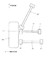
図1は、サスペンション装置を上方から見た状態を示す模式的平面図である。
図2は、サスペンション装置を車両前方側から見た状態を示す模式的前面図である。
Embodiments of a suspension device to which the present invention is applied will be described below.
The suspension device according to the embodiment is a dual link (parallel link) strut suspension used as a rear wheel suspension of an automobile such as a passenger car.
FIG. 1 is a schematic plan view showing the suspension device as viewed from above.
FIG. 2 is a schematic front view showing the suspension device as viewed from the front side of the vehicle.
サスペンション装置は、フロントラテラルアーム10、リアラテラルアーム20、トレーリングアーム30、ストラットアッシー40を備えている。
フロントラテラルアーム(トランスバースリンク)10及びリアラテラルアーム(トランスバースリンク)20は、後輪用のハブベアリングを収容する図示しないハウジングと図示しない車体又はサブフレーム等の車体側構造部材(以下「車体」と総称する)との間にわたして設けられ、上方からみたときにほぼ車幅方向に沿って延在するサスペンションアームである。これらはほぼ並行して車両の前後方向に離間して配置されている。また、フロントラテラルアーム10及びリアラテラルアーム20は、そのハウジング側、車体側との接続部が、それぞれ後輪車軸の車両前方側、後方側となるように、車両前後方向において車軸を挟んで配置されている。
フロントラテラルアーム10及びリアラテラルアーム20は、車両の静止時に車両の前方側から見たときに、車輪側(車幅方向外側)の端部が車体側(車幅方向内側)の端部よりも低くなるように下反角をつけて配置されている。
The suspension device includes a front
A front lateral arm (transverse link) 10 and a rear lateral arm (transverse link) 20 include a housing (not shown) that houses a hub bearing for a rear wheel, and a vehicle body side structural member (hereinafter referred to as “vehicle body” such as a vehicle body or a subframe (not shown)). And a suspension arm that extends substantially along the vehicle width direction when viewed from above. These are arranged substantially in parallel and spaced apart in the longitudinal direction of the vehicle. Further, the front
When the front
フロントラテラルアーム10は、車体側、ハウジング側の端部にそれぞれ車体側ブッシュ11、ハウジング側ブッシュ12を備えている。
また、リアラテラルアーム20も、車体側、ハウジング側の端部にそれぞれ車体側ブッシュ21、ハウジング側ブッシュ22を備えている。
The front
The rear
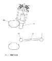
図3は、フロントラテラルアーム10の車体側ブッシュ11周辺部を車両前方側から見た模式的外観図である。
車体側ブッシュ11は、フロントラテラルアーム10の円筒部10aに圧入されて使用されるものであって、外筒110、内筒120、クッションラバー(ゴム部)130を備えている。
外筒110は、例えば金属等のクッションラバー130よりも硬度が高い硬質材料によって円筒状に形成され、フロントラテラルアーム10の円筒部10aに圧入され固定される部分である。
内筒120は、硬質材料によって形成され、外筒110の内径側に挿入される部材である。内筒120には、車体側ブッシュ11を車体側支持部に固定するボルトが挿入されるボルト孔121が形成されている。このボルト孔121は、外筒110に対してほぼ同心に配置される。
また、外筒110の内周面と対向する内筒120の外周面部には、外筒110側へ張り出して形成された張出部122が設けられている。張出部122は、ボルト孔121の中心軸から見て、ハウジング側ブッシュ12とは反対側の方向に設けられている。また、張出部122が外筒110の内周面と最も近接する突端部においては、その表面は平面又は緩い曲率をもった凸面として形成されている。
FIG. 3 is a schematic external view of the periphery of the vehicle
The vehicle
The
The
In addition, a protruding
クッションラバー130は、例えば防振機能を有するゴム系材料によって形成され、外筒110の内周面と内筒120の外周面との間に充填されている。外筒110及び内筒120は、このクッションラバー130と加硫接着によって接合されている。
ここで、クッションラバー130の車体側ブッシュ11の径方向における厚みは、上述した内筒120の張出部122が設けられた領域(フロントラテラルアーム10に引張荷重が作用した際に圧縮される領域)においては他の部分(フロントラテラルアーム10に圧縮荷重が作用した際に圧縮される領域等)よりも薄くなっている。
また、リアラテラルアーム20の車体側ブッシュ21も、上述したフロントラテラルアーム10の車体側ブッシュ11と同様の構成を備えるが、そのバネ特性は、以下説明する通りフロント側と異なるように材質、寸法等をチューニングされている。
The
Here, the thickness of the
Further, the vehicle
図4は、フロントラテラルアーム10及びリアラテラルアーム20の車体側ブッシュ11,21のバネ特性を示すグラフである。
図4(a)、図4(b)は、それぞれフロント側、リア側の特性を示している。縦軸は各ラテラルアームに作用する引張力及び圧縮力(荷重)を示しており、上側が引張力、下側が圧縮力をそれぞれ示している。横軸はブッシュの内筒と外筒との径方向の相対変位を示している。
FIG. 4 is a graph showing spring characteristics of the vehicle
FIG. 4A and FIG. 4B show the characteristics on the front side and the rear side, respectively. The vertical axis shows the tensile force and compressive force (load) acting on each lateral arm, with the upper side showing the tensile force and the lower side showing the compressive force. The horizontal axis indicates the relative displacement in the radial direction between the inner cylinder and the outer cylinder of the bush.
フロントラテラルアーム10及びリアラテラルアーム20には、例えば車両の静止時や直進走行時のように、旋回時の横力が作用していない場合であっても、タイヤの接地荷重に起因する引張力が作用している。このような引張力を、「初期引張力(初期引張荷重)」と称して説明する。
フロントラテラルアーム10及びリアラテラルアーム20の車体側ブッシュ11,21のバネ特性は、ともに各ラテラルアームに作用する引張力の増加に応じてバネ定数が増加する非線形特性を有し、特に、所定の変曲点近傍におけるバネ定数の変化率は、これ以外の領域でのバネ定数の変化率よりも大きくなっている。
The front
The spring characteristics of the vehicle
フロント側の車体側ブッシュ11は、フロントラテラルアーム10の引張力が初期引張力よりも小さい範囲に上述した変曲点Ifが設けられている。
リア側の車体側ブッシュ21は、リアラテラルアーム20の引張力が初期引張力よりも大きい範囲に上述した変曲点Irが設けられている。
The vehicle
The rear vehicle
ハウジング側ブッシュ12、及び、ハウジング側ブッシュ22には、単純円筒状に形成された外筒、内筒及びこれらの間に配置されたクッションラバーを備える一般的なゴムブッシュが適用される。
For the housing-
トレーリングアーム30は、車両の前後方向にほぼ沿って配置され、前端部を車体に接続され、後端部をハウジングの前端部に接続されたサスペンションアームである。
ストラットアッシー40は、コイルスプリング及びショックアブソーバをアセンブリ化したものであって、上端部は車体に固定され、下端部はハウジングの上端部に固定されている。
The trailing
The
図5は、実施例のサスペンション装置における後輪の接地点横力とトー角との相関を示すグラフである。
図5において、横軸は後輪が発生する接地点横力を示し、右側が車幅方向内向き(旋回外輪側)、左側が車幅方向外向き(旋回内輪側)を示している。縦軸は後輪のトー角を示し、上側がトーイン側、下側がトーアウト側を示している。
図5に示すように、横力がほぼゼロの状態から、旋回外輪側に増加すると、横力が小さい初期状態においては、後輪はまずトーアウト側にステアされ、その後横力の増大に応じてトーアウト角が減少に転じ、さらにトーイン側にステアされる。旋回外輪側においては、フロント側の車体側ブッシュ11の変形量がリア側の車体側ブッシュ21の変形量よりも大きいとトーイン傾向となり、小さいとトーアウト傾向となる。
これに対し、横力がほぼゼロの状態から、旋回内輪側に増加すると、横力が小さい初期状態においては、後輪はまずトーイン側にステアされ、その後横力の増大に応じてトーイン角が減少に転じ、さらにトーアウト側にステアされる。旋回内輪側においては、フロント側の車体側ブッシュ11の変形量がリア側の車体側ブッシュ21の変形量よりも大きいとトーアウト傾向となり、小さいとトーイン傾向となる。
FIG. 5 is a graph showing the correlation between the ground contact point lateral force of the rear wheel and the toe angle in the suspension device of the example.
In FIG. 5, the horizontal axis indicates the ground contact point lateral force generated by the rear wheel, the right side indicates inward in the vehicle width direction (turning outer wheel side), and the left side indicates in the vehicle width direction outward (turning inner wheel side). The vertical axis shows the toe angle of the rear wheel, the upper side shows the toe-in side, and the lower side shows the toe-out side.
As shown in FIG. 5, when the lateral force increases from the almost zero state to the turning outer wheel side, in the initial state where the lateral force is small, the rear wheel is first steered to the toe-out side, and then the lateral force increases. The toe-out angle starts to decrease and is steered to the toe-in side. On the turning outer wheel side, if the amount of deformation of the vehicle
On the other hand, if the lateral force increases from the almost zero state toward the turning inner wheel side, in the initial state where the lateral force is small, the rear wheel is steered first to the toe-in side, and then the toe-in angle is increased according to the increase in the lateral force. It starts to decrease and is steered to the toe-out side. On the turning inner wheel side, a toe-out tendency occurs when the deformation amount of the vehicle
次に、上述した実施例の効果を、以下説明する本発明の比較例のサスペンション装置と対比して説明する。
比較例のサスペンション装置は、実施例の車体側ブッシュ11,21に代えて、ハウジング側ブッシュ12,22と同様の一般的なブッシュを備えたものである。
図6は、実施例のサスペンション装置と比較例のサスペンション装置におけるステアリングホイール舵角、後輪の車軸軸力、車両のヨー角速度の履歴を示すグラフである。
図6(a)、図6(b)、図6(c)の横軸は全て時間を示し、そのスケールは各図共通に図示している。
図6(a)の縦軸は、ステアリングホイールの舵角を示している。
図6(b)の縦軸は、後輪の車軸軸力を示し、上側が旋回中心側への力を示している。
図6(c)の縦軸は、車両のヨー角速度を示している。
Next, the effects of the above-described embodiment will be described in comparison with a suspension device of a comparative example of the present invention described below.
The suspension device of the comparative example includes general bushes similar to the
FIG. 6 is a graph showing the history of the steering wheel rudder angle, the axle force of the rear wheel, and the yaw angular velocity of the vehicle in the suspension device of the example and the suspension device of the comparative example.
6 (a), 6 (b), and 6 (c) all indicate time, and the scale is shown in common in each figure.
The vertical axis | shaft of Fig.6 (a) has shown the steering angle of the steering wheel.
The vertical axis in FIG. 6B shows the axle force of the rear wheel, and the upper side shows the force toward the turning center.
The vertical axis in FIG. 6C shows the yaw angular velocity of the vehicle.
実施例においては、旋回初期に後輪が前輪の操舵方向と逆相方向にステアされることによって、図6(b)に示すように、後輪の車軸軸力が一時的に外向きに作用する。このような車軸軸力は、車両のヨーイング発生を促進することから、図6(c)に示すように、実施例ではコンプライアンスオーバーステアによって比較例よりもヨー角速度の立ち上がりが早くなっており、車両のヨー応答性を向上することができる。また、これによって、前輪の横滑り角が増大し、タイヤのセルフアライニングトルクが増え、ステアリングホイールの手応えを向上して運転者が得るフィーリングを向上することができる。
その後、定常旋回状態では実施例は後輪が前輪の操舵方向と同相方向にステアされることから、実施例ではコンプライアンスアンダーステアによって比較例よりもヨー角速度の発生が穏やかとなってヨーイングが早期に収束し、車両の安定性が向上する。
また、実施例によれば、例えばアクチュエータを用いた後輪操舵装置のような複雑なデバイスを設けることなく後輪を旋回初期には前輪と逆相方向、定常旋回では同相方向にステアすることができるから、車両の構造を簡素化し、重量やコストを低減することができる。
In the embodiment, when the rear wheel is steered in the opposite phase to the steering direction of the front wheel at the beginning of turning, the axle force of the rear wheel acts temporarily outward as shown in FIG. 6B. To do. Such an axle force promotes the occurrence of yawing of the vehicle. Therefore, as shown in FIG. 6C, in the embodiment, the rise of the yaw angular velocity is faster than that of the comparative example due to compliance oversteer. Yaw responsiveness can be improved. This also increases the side slip angle of the front wheels, increases the self-aligning torque of the tire, improves the response of the steering wheel, and improves the feeling obtained by the driver.
After that, in the steady turning state, in the example, the rear wheels are steered in the same phase as the steering direction of the front wheels, so in the example, the compliance understeer causes the yaw angular velocity to be generated more gently than the comparative example, and yawing converges earlier. In addition, the stability of the vehicle is improved.
Further, according to the embodiment, the rear wheel can be steered in the opposite phase direction to the front wheel at the beginning of turning and in the same phase direction during steady turning without providing a complicated device such as a rear wheel steering device using an actuator. Therefore, the structure of the vehicle can be simplified and the weight and cost can be reduced.
(変形例)
本発明は、以上説明した実施例に限定されることなく、種々の変形や変更が可能であって、それらも本発明の技術的範囲内である。
(1)本発明が適用されるサスペンション装置の形式は、実施例のようなマクファーソンストラット式サスペンションやデュアルリンクストラット式サスペンションに限らず、例えばダブルウィッシュボーン式やマルチリンク式等の他の形式のサスペンション装置にも適用することができる。
(2)サスペンションの弾性体ブッシュに所望の非線形特性を与える手段は、上述した各実施例に限定されず、適宜変更することができる。例えば、弾性体ブッシュにすぐりを形成したり、中間板(インターリーフ)等の硬質部材を埋設してもよい。また、これら複数の手段を組み合わせて用いてもよい。
(3)各実施例においては、変曲点を有する非線形特性の弾性体ブッシュをサスペンションアームと車体側との接続部に設けているが、これに限らず、このようなブッシュをハウジングやスピンドル等の車輪ハブ支持体との接続部に設けたり、車体側との両側に設けてもよい。
(Modification)
The present invention is not limited to the embodiments described above, and various modifications and changes are possible, and these are also within the technical scope of the present invention.
(1) The type of the suspension device to which the present invention is applied is not limited to the McPherson strut type suspension or the dual link strut type suspension as in the embodiment, but other types of suspensions such as a double wishbone type and a multilink type. It can also be applied to devices.
(2) Means for imparting desired nonlinear characteristics to the elastic bush of the suspension is not limited to the above-described embodiments, and can be changed as appropriate. For example, a curl may be formed on the elastic body bush, or a hard member such as an intermediate plate (interleaf) may be embedded. Moreover, you may use combining these several means.
(3) In each of the embodiments, an elastic bush having a non-linear characteristic having an inflection point is provided at a connection portion between the suspension arm and the vehicle body side. It may be provided at the connecting portion with the wheel hub support or on both sides of the vehicle body side.
10 フロントラテラルアーム
11 車体側ブッシュ
12 ハウジング側ブッシュ
20 リアラテラルアーム
21 車体側ブッシュ
22 ハウジング側ブッシュ
30 トレーリングアーム
40 ストラットアッシー
110 外筒
120 内筒
121 ボルト孔
122 張出部
130 クッションラバー
DESCRIPTION OF
Claims (4)
一方の端部を前記車輪ハブ支持体に揺動可能に接続され、他方の端部を車体側支持部に対して揺動可能に接続された前側サスペンションアームと、
一方の端部を前記車輪ハブ支持体の前記前側サスペンションアームとの接続部よりも後方側の部分に揺動可能に接続され、他方の端部を車体側支持部の前記前側サスペンションアームとの接続部よりも後方側の部分に揺動可能に接続された後側サスペンションアームと、
前記前側サスペンションアームと前記車体側支持部又は前記車輪ハブ支持体との接続部の少なくとも一方に設けられ、前記前側サスペンションアームに作用する引張力及び圧縮力に応じて変形する弾性体を有する前側弾性体ブッシュと、
前記後側サスペンションアームと前記車体側支持部又は前記車輪ハブ支持体との接続部の少なくとも一方に設けられ、前記後側サスペンションアームに作用する引張力及び圧縮力に応じて変形する弾性体を有する後側弾性体ブッシュと
を備えるサスペンション装置であって、
前記前側弾性体ブッシュの前記前側サスペンションアームの引張力及び圧縮力に対するバネ定数は、前記引張力が前記車輪の接地荷重に起因する初期引張力よりも小さい領域において、該引張力の増大に応じて増大する非線形特性を有し、
前記前側弾性体ブッシュの前記バネ定数の変曲点は、前記引張力が前記初期引張力よりも小さい範囲に設けられ、
前記後側弾性体ブッシュの前記後側サスペンションアームの引張力及び圧縮力に対するバネ定数は、前記引張力が前記車輪の接地荷重に起因する初期引張力よりも大きい領域において、該引張力の増大に応じて増大する非線形特性を有し、
前記後側弾性体ブッシュの前記バネ定数の変曲点は、前記引張力が前記初期引張力よりも大きい範囲に設けられ、
旋回内輪側及び旋回外輪側の前記後輪を横力が小さい状態では前輪と逆相方向にステアしかつ横力の増大に応じて前輪と同相方向にステアすること
を特徴とするサスペンション装置。 A wheel hub support for rotatably supporting the rear wheel of the vehicle ;
A front suspension arm having one end pivotably connected to the wheel hub support and the other end pivotably connected to the vehicle body support;
One end of the wheel hub support is swingably connected to a portion on the rear side of the connection with the front suspension arm, and the other end is connected to the front suspension arm of the vehicle body support. A rear suspension arm swingably connected to a portion on the rear side of the unit,
A front-side elasticity having an elastic body that is provided in at least one of the connection portions between the front-side suspension arm and the vehicle-body-side support portion or the wheel hub support body and deforms according to a tensile force and a compressive force acting on the front-side suspension arm. Body bush,
An elastic body is provided at at least one of the connecting portions between the rear suspension arm and the vehicle body side support portion or the wheel hub support body, and is deformed in accordance with a tensile force and a compressive force acting on the rear suspension arm. A suspension device comprising a rear elastic body bush,
The spring constant for the tensile force and the compressive force of the front suspension arm of the front elastic body bush depends on the increase in the tensile force in a region where the tensile force is smaller than the initial tensile force due to the ground contact load of the wheel. Has increasing nonlinear properties,
The inflection point of the spring constant of the front elastic body bush is provided in a range where the tensile force is smaller than the initial tensile force,
The spring constant for the tensile force and the compressive force of the rear suspension arm of the rear elastic body bush is that the tensile force increases in a region where the tensile force is larger than the initial tensile force due to the ground contact load of the wheel. have a nonlinear characteristic increases with,
The inflection point of the spring constant of the rear elastic body bush is provided in a range where the tensile force is larger than the initial tensile force,
A suspension device characterized in that the rear wheels on the turning inner wheel side and the turning outer wheel side are steered in a direction opposite to the front wheel in a state where the lateral force is small, and steered in the same phase as the front wheel in accordance with an increase in the lateral force .
前記前側サスペンションアームに作用する引張力が前記初期引張力よりも小さくかつ前記前側弾性体ブッシュのバネ定数が変化する変曲点よりも大きい範囲となる車輪接地点横力の範囲においては、該車輪接地点横力に対する前記前側弾性体ブッシュの横方向変形量の変化率は前記後側弾性体ブッシュの横方向変形量の変化率よりも小さく、
前記前側サスペンションアームに作用する引張力が前記前側弾性体ブッシュのバネ定数が変化する変曲点よりも小さく、又は、前記前側サスペンションアームに圧縮力が作用する範囲となる車輪接地点横力の範囲においては、該車輪接地点横力に対する前記前側弾性体ブッシュの横方向変形量の変化率は前記後側弾性体ブッシュの横方向変形量の変化率よりも大きいこと
を特徴とするサスペンション装置。 The suspension device according to claim 1,
In the wheel contact point lateral force range in which the tensile force acting on the front suspension arm is smaller than the initial tensile force and larger than the inflection point at which the spring constant of the front elastic body bush changes, the wheel The rate of change of the lateral deformation amount of the front elastic body bush with respect to the contact point lateral force is smaller than the rate of change of the lateral deformation amount of the rear elastic body bush,
The range of the wheel contact point lateral force in which the tensile force acting on the front suspension arm is smaller than the inflection point where the spring constant of the front elastic body bush changes or the compression force acts on the front suspension arm In the suspension device, the change rate of the lateral deformation amount of the front elastic body bush with respect to the wheel contact point lateral force is larger than the change rate of the lateral deformation amount of the rear elastic body bush.
前記後側サスペンションアームに作用する引張力が前記初期引張力よりも大きくかつ前記後側弾性体ブッシュのバネ定数が変化する変曲点よりも小さい範囲となる車輪接地点横力の範囲においては、該車輪接地点横力に対する前記後側弾性体ブッシュの横方向変形量の変化率は前記前側弾性体ブッシュの横方向変形量の変化率よりも大きく、
前記後側サスペンションアームに作用する引張力が前記後側弾性体ブッシュのバネ定数が変化する変曲点よりも大きい範囲となる車輪接地点横力の範囲においては、該車輪接地点横力に対する前記後側弾性体ブッシュの横方向変形量の変化率は前記前側弾性体ブッシュの横方向変形量の変化率よりも小さいこと
を特徴とするサスペンション装置。 In the suspension device according to claim 1 or 2,
In the wheel contact point lateral force range in which the tensile force acting on the rear suspension arm is larger than the initial tensile force and smaller than the inflection point at which the spring constant of the rear elastic body bush changes. The rate of change of the lateral deformation amount of the rear elastic body bush with respect to the wheel contact point lateral force is greater than the rate of change of the lateral deformation amount of the front elastic body bush ,
In the range of the wheel contact point lateral force in which the tensile force acting on the rear suspension arm is greater than the inflection point at which the spring constant of the rear elastic body bush changes, the wheel contact point lateral force is A suspension device, wherein a change rate of a lateral deformation amount of the rear elastic body bushing is smaller than a change rate of a lateral deformation amount of the front elastic body bushing.
前記前側弾性体ブッシュ及び前記後側弾性体ブッシュの前記弾性体は、前記前側サスペンションアーム及び前記後側サスペンションアームに引張力が作用した際に圧縮される部分の圧縮方向における厚みを、前記前側サスペンションアーム及び前記後側サスペンションアームに圧縮力が作用した際に圧縮される部分の圧縮方向における厚みよりも薄くしたこと
を特徴とするサスペンション装置。
In the suspension device according to any one of claims 1 to 3,
The elastic body of the front elastic body bush and the rear elastic body bush has a thickness in a compression direction of a portion compressed when a tensile force acts on the front suspension arm and the rear suspension arm, and the front suspension A suspension device characterized in that it is thinner than a thickness in a compression direction of a portion compressed when a compressive force is applied to the arm and the rear suspension arm.
Priority Applications (1)
| Application Number | Priority Date | Filing Date | Title |
|---|---|---|---|
| JP2007090592A JP5057438B2 (en) | 2007-03-30 | 2007-03-30 | Suspension device |
Applications Claiming Priority (1)
| Application Number | Priority Date | Filing Date | Title |
|---|---|---|---|
| JP2007090592A JP5057438B2 (en) | 2007-03-30 | 2007-03-30 | Suspension device |
Publications (2)
| Publication Number | Publication Date |
|---|---|
| JP2008247182A JP2008247182A (en) | 2008-10-16 |
| JP5057438B2 true JP5057438B2 (en) | 2012-10-24 |
Family
ID=39972647
Family Applications (1)
| Application Number | Title | Priority Date | Filing Date |
|---|---|---|---|
| JP2007090592A Expired - Fee Related JP5057438B2 (en) | 2007-03-30 | 2007-03-30 | Suspension device |
Country Status (1)
| Country | Link |
|---|---|
| JP (1) | JP5057438B2 (en) |
Families Citing this family (5)
| Publication number | Priority date | Publication date | Assignee | Title |
|---|---|---|---|---|
| JP5246296B2 (en) * | 2011-05-16 | 2013-07-24 | 日産自動車株式会社 | Suspension structure, bush structure, suspension characteristic adjustment method |
| JP5293770B2 (en) | 2011-05-16 | 2013-09-18 | 日産自動車株式会社 | Suspension structure, suspension link arrangement method |
| US8628101B2 (en) | 2011-05-16 | 2014-01-14 | Nissan Motor Co., Ltd. | Suspension structure, bush structure and suspension characteristic adjusting method |
| JP6148515B2 (en) * | 2013-03-28 | 2017-06-14 | 株式会社Subaru | Suspension device |
| DE102014104176A1 (en) * | 2013-03-28 | 2014-10-02 | Fuji Jukogyo Kabushiki Kaisha | suspension device |
Family Cites Families (6)
| Publication number | Priority date | Publication date | Assignee | Title |
|---|---|---|---|---|
| JPS60148708A (en) * | 1984-01-13 | 1985-08-06 | Mazda Motor Corp | Automobile's suspension |
| JPS61190707U (en) * | 1985-05-22 | 1986-11-27 | ||
| JPH085289B2 (en) * | 1986-05-19 | 1996-01-24 | マツダ株式会社 | Car suspension |
| JPH058623A (en) * | 1991-07-01 | 1993-01-19 | Mazda Motor Corp | Suspension device of vehicle |
| JP3796767B2 (en) * | 1995-05-26 | 2006-07-12 | 日産自動車株式会社 | Bushing and vehicle suspension mounting structure |
| JP3701958B2 (en) * | 2004-05-31 | 2005-10-05 | 本田技研工業株式会社 | Subframe mounting bush |
-
2007
- 2007-03-30 JP JP2007090592A patent/JP5057438B2/en not_active Expired - Fee Related
Also Published As
| Publication number | Publication date |
|---|---|
| JP2008247182A (en) | 2008-10-16 |
Similar Documents
| Publication | Publication Date | Title |
|---|---|---|
| JP5136453B2 (en) | Stabilizer link mounting structure | |
| US11433725B2 (en) | Bushing and vehicle suspension device | |
| JP4751743B2 (en) | Suspension bush and double joint type suspension mechanism using the same | |
| JP5057438B2 (en) | Suspension device | |
| CN117681605A (en) | Suspension with jounce bumper balanced for caster control | |
| US11473646B2 (en) | Bushing and vehicle suspension device | |
| JP5057436B2 (en) | Suspension device | |
| JP5057434B2 (en) | Suspension device | |
| JP2008249081A (en) | Bush and suspension device | |
| JP2008201307A (en) | Stabilizer device | |
| JP5057437B2 (en) | Suspension device | |
| JP7193964B2 (en) | stabilizer device | |
| JP4640847B2 (en) | Suspension device | |
| JP6139212B2 (en) | Suspension device | |
| JP2007106190A (en) | Ball joint and stabilizer device for vehicle | |
| KR101316500B1 (en) | Toe adjusting device for rear suspension system | |
| US20230150326A1 (en) | Suspension | |
| JP5374282B2 (en) | Suspension device | |
| JP2004306630A (en) | Supporting structure of trailing arm | |
| US11840121B2 (en) | Suspension | |
| JP6148515B2 (en) | Suspension device | |
| JP2010023599A (en) | Method for adjusting camber angle in double wishbone type suspension | |
| JP2010047041A (en) | Suspension bush | |
| JP2008201306A (en) | Stabilizer device | |
| JP6166084B2 (en) | Suspension device |
Legal Events
| Date | Code | Title | Description |
|---|---|---|---|
| A621 | Written request for application examination |
Free format text: JAPANESE INTERMEDIATE CODE: A621 Effective date: 20100225 |
|
| A977 | Report on retrieval |
Free format text: JAPANESE INTERMEDIATE CODE: A971007 Effective date: 20111028 |
|
| A131 | Notification of reasons for refusal |
Free format text: JAPANESE INTERMEDIATE CODE: A131 Effective date: 20111115 |
|
| A521 | Request for written amendment filed |
Free format text: JAPANESE INTERMEDIATE CODE: A523 Effective date: 20120113 |
|
| TRDD | Decision of grant or rejection written | ||
| A01 | Written decision to grant a patent or to grant a registration (utility model) |
Free format text: JAPANESE INTERMEDIATE CODE: A01 Effective date: 20120703 |
|
| A01 | Written decision to grant a patent or to grant a registration (utility model) |
Free format text: JAPANESE INTERMEDIATE CODE: A01 |
|
| A61 | First payment of annual fees (during grant procedure) |
Free format text: JAPANESE INTERMEDIATE CODE: A61 Effective date: 20120726 |
|
| FPAY | Renewal fee payment (event date is renewal date of database) |
Free format text: PAYMENT UNTIL: 20150810 Year of fee payment: 3 |
|
| R150 | Certificate of patent or registration of utility model |
Ref document number: 5057438 Country of ref document: JP Free format text: JAPANESE INTERMEDIATE CODE: R150 Free format text: JAPANESE INTERMEDIATE CODE: R150 |
|
| S531 | Written request for registration of change of domicile |
Free format text: JAPANESE INTERMEDIATE CODE: R313531 |
|
| R350 | Written notification of registration of transfer |
Free format text: JAPANESE INTERMEDIATE CODE: R350 |
|
| R250 | Receipt of annual fees |
Free format text: JAPANESE INTERMEDIATE CODE: R250 |
|
| R250 | Receipt of annual fees |
Free format text: JAPANESE INTERMEDIATE CODE: R250 |
|
| S533 | Written request for registration of change of name |
Free format text: JAPANESE INTERMEDIATE CODE: R313533 |
|
| R350 | Written notification of registration of transfer |
Free format text: JAPANESE INTERMEDIATE CODE: R350 |
|
| R250 | Receipt of annual fees |
Free format text: JAPANESE INTERMEDIATE CODE: R250 |
|
| R250 | Receipt of annual fees |
Free format text: JAPANESE INTERMEDIATE CODE: R250 |
|
| R250 | Receipt of annual fees |
Free format text: JAPANESE INTERMEDIATE CODE: R250 |
|
| R250 | Receipt of annual fees |
Free format text: JAPANESE INTERMEDIATE CODE: R250 |
|
| R250 | Receipt of annual fees |
Free format text: JAPANESE INTERMEDIATE CODE: R250 |
|
| LAPS | Cancellation because of no payment of annual fees |