EP2524154B1 - Manual transmission neutral switch diagnostic and movement prevention method and system for a vehicle - Google Patents
Manual transmission neutral switch diagnostic and movement prevention method and system for a vehicle Download PDFInfo
- Publication number
- EP2524154B1 EP2524154B1 EP11700586.8A EP11700586A EP2524154B1 EP 2524154 B1 EP2524154 B1 EP 2524154B1 EP 11700586 A EP11700586 A EP 11700586A EP 2524154 B1 EP2524154 B1 EP 2524154B1
- Authority
- EP
- European Patent Office
- Prior art keywords
- vehicle
- wheel speed
- processor
- speed sensor
- control system
- Prior art date
- Legal status (The legal status is an assumption and is not a legal conclusion. Google has not performed a legal analysis and makes no representation as to the accuracy of the status listed.)
- Not-in-force
Links
Images


Classifications
-
- B—PERFORMING OPERATIONS; TRANSPORTING
- B60—VEHICLES IN GENERAL
- B60W—CONJOINT CONTROL OF VEHICLE SUB-UNITS OF DIFFERENT TYPE OR DIFFERENT FUNCTION; CONTROL SYSTEMS SPECIALLY ADAPTED FOR HYBRID VEHICLES; ROAD VEHICLE DRIVE CONTROL SYSTEMS FOR PURPOSES NOT RELATED TO THE CONTROL OF A PARTICULAR SUB-UNIT
- B60W30/00—Purposes of road vehicle drive control systems not related to the control of a particular sub-unit, e.g. of systems using conjoint control of vehicle sub-units
- B60W30/18—Propelling the vehicle
- B60W30/18009—Propelling the vehicle related to particular drive situations
- B60W30/18054—Propelling the vehicle related to particular drive situations at stand still, e.g. engine in idling state
-
- B—PERFORMING OPERATIONS; TRANSPORTING
- B60—VEHICLES IN GENERAL
- B60W—CONJOINT CONTROL OF VEHICLE SUB-UNITS OF DIFFERENT TYPE OR DIFFERENT FUNCTION; CONTROL SYSTEMS SPECIALLY ADAPTED FOR HYBRID VEHICLES; ROAD VEHICLE DRIVE CONTROL SYSTEMS FOR PURPOSES NOT RELATED TO THE CONTROL OF A PARTICULAR SUB-UNIT
- B60W30/00—Purposes of road vehicle drive control systems not related to the control of a particular sub-unit, e.g. of systems using conjoint control of vehicle sub-units
- B60W30/18—Propelling the vehicle
- B60W30/18009—Propelling the vehicle related to particular drive situations
- B60W30/18027—Drive off, accelerating from standstill
-
- B—PERFORMING OPERATIONS; TRANSPORTING
- B60—VEHICLES IN GENERAL
- B60W—CONJOINT CONTROL OF VEHICLE SUB-UNITS OF DIFFERENT TYPE OR DIFFERENT FUNCTION; CONTROL SYSTEMS SPECIALLY ADAPTED FOR HYBRID VEHICLES; ROAD VEHICLE DRIVE CONTROL SYSTEMS FOR PURPOSES NOT RELATED TO THE CONTROL OF A PARTICULAR SUB-UNIT
- B60W30/00—Purposes of road vehicle drive control systems not related to the control of a particular sub-unit, e.g. of systems using conjoint control of vehicle sub-units
- B60W30/18—Propelling the vehicle
- B60W30/192—Mitigating problems related to power-up or power-down of the driveline, e.g. start-up of a cold engine
-
- F—MECHANICAL ENGINEERING; LIGHTING; HEATING; WEAPONS; BLASTING
- F16—ENGINEERING ELEMENTS AND UNITS; GENERAL MEASURES FOR PRODUCING AND MAINTAINING EFFECTIVE FUNCTIONING OF MACHINES OR INSTALLATIONS; THERMAL INSULATION IN GENERAL
- F16H—GEARING
- F16H61/00—Control functions within control units of change-speed- or reversing-gearings for conveying rotary motion ; Control of exclusively fluid gearing, friction gearing, gearings with endless flexible members or other particular types of gearing
- F16H61/12—Detecting malfunction or potential malfunction, e.g. fail safe ; Circumventing or fixing failures
-
- B—PERFORMING OPERATIONS; TRANSPORTING
- B60—VEHICLES IN GENERAL
- B60W—CONJOINT CONTROL OF VEHICLE SUB-UNITS OF DIFFERENT TYPE OR DIFFERENT FUNCTION; CONTROL SYSTEMS SPECIALLY ADAPTED FOR HYBRID VEHICLES; ROAD VEHICLE DRIVE CONTROL SYSTEMS FOR PURPOSES NOT RELATED TO THE CONTROL OF A PARTICULAR SUB-UNIT
- B60W10/00—Conjoint control of vehicle sub-units of different type or different function
- B60W10/04—Conjoint control of vehicle sub-units of different type or different function including control of propulsion units
- B60W10/06—Conjoint control of vehicle sub-units of different type or different function including control of propulsion units including control of combustion engines
-
- B—PERFORMING OPERATIONS; TRANSPORTING
- B60—VEHICLES IN GENERAL
- B60W—CONJOINT CONTROL OF VEHICLE SUB-UNITS OF DIFFERENT TYPE OR DIFFERENT FUNCTION; CONTROL SYSTEMS SPECIALLY ADAPTED FOR HYBRID VEHICLES; ROAD VEHICLE DRIVE CONTROL SYSTEMS FOR PURPOSES NOT RELATED TO THE CONTROL OF A PARTICULAR SUB-UNIT
- B60W50/00—Details of control systems for road vehicle drive control not related to the control of a particular sub-unit, e.g. process diagnostic or vehicle driver interfaces
- B60W50/02—Ensuring safety in case of control system failures, e.g. by diagnosing, circumventing or fixing failures
- B60W50/0205—Diagnosing or detecting failures; Failure detection models
- B60W2050/0215—Sensor drifts or sensor failures
-
- B—PERFORMING OPERATIONS; TRANSPORTING
- B60—VEHICLES IN GENERAL
- B60W—CONJOINT CONTROL OF VEHICLE SUB-UNITS OF DIFFERENT TYPE OR DIFFERENT FUNCTION; CONTROL SYSTEMS SPECIALLY ADAPTED FOR HYBRID VEHICLES; ROAD VEHICLE DRIVE CONTROL SYSTEMS FOR PURPOSES NOT RELATED TO THE CONTROL OF A PARTICULAR SUB-UNIT
- B60W2520/00—Input parameters relating to overall vehicle dynamics
- B60W2520/28—Wheel speed
-
- F—MECHANICAL ENGINEERING; LIGHTING; HEATING; WEAPONS; BLASTING
- F16—ENGINEERING ELEMENTS AND UNITS; GENERAL MEASURES FOR PRODUCING AND MAINTAINING EFFECTIVE FUNCTIONING OF MACHINES OR INSTALLATIONS; THERMAL INSULATION IN GENERAL
- F16H—GEARING
- F16H59/00—Control inputs to control units of change-speed- or reversing-gearings for conveying rotary motion
- F16H59/36—Inputs being a function of speed
- F16H59/44—Inputs being a function of speed dependent on machine speed, e.g. the vehicle speed
- F16H2059/446—Detecting vehicle stop, i.e. the vehicle is at stand still, e.g. for engaging parking lock
-
- F—MECHANICAL ENGINEERING; LIGHTING; HEATING; WEAPONS; BLASTING
- F16—ENGINEERING ELEMENTS AND UNITS; GENERAL MEASURES FOR PRODUCING AND MAINTAINING EFFECTIVE FUNCTIONING OF MACHINES OR INSTALLATIONS; THERMAL INSULATION IN GENERAL
- F16H—GEARING
- F16H59/00—Control inputs to control units of change-speed- or reversing-gearings for conveying rotary motion
- F16H59/68—Inputs being a function of gearing status
- F16H2059/6807—Status of gear-change operation, e.g. clutch fully engaged
-
- F—MECHANICAL ENGINEERING; LIGHTING; HEATING; WEAPONS; BLASTING
- F16—ENGINEERING ELEMENTS AND UNITS; GENERAL MEASURES FOR PRODUCING AND MAINTAINING EFFECTIVE FUNCTIONING OF MACHINES OR INSTALLATIONS; THERMAL INSULATION IN GENERAL
- F16H—GEARING
- F16H61/00—Control functions within control units of change-speed- or reversing-gearings for conveying rotary motion ; Control of exclusively fluid gearing, friction gearing, gearings with endless flexible members or other particular types of gearing
- F16H61/12—Detecting malfunction or potential malfunction, e.g. fail safe ; Circumventing or fixing failures
- F16H2061/1208—Detecting malfunction or potential malfunction, e.g. fail safe ; Circumventing or fixing failures with diagnostic check cycles; Monitoring of failures
-
- F—MECHANICAL ENGINEERING; LIGHTING; HEATING; WEAPONS; BLASTING
- F16—ENGINEERING ELEMENTS AND UNITS; GENERAL MEASURES FOR PRODUCING AND MAINTAINING EFFECTIVE FUNCTIONING OF MACHINES OR INSTALLATIONS; THERMAL INSULATION IN GENERAL
- F16H—GEARING
- F16H59/00—Control inputs to control units of change-speed- or reversing-gearings for conveying rotary motion
- F16H59/36—Inputs being a function of speed
-
- Y—GENERAL TAGGING OF NEW TECHNOLOGICAL DEVELOPMENTS; GENERAL TAGGING OF CROSS-SECTIONAL TECHNOLOGIES SPANNING OVER SEVERAL SECTIONS OF THE IPC; TECHNICAL SUBJECTS COVERED BY FORMER USPC CROSS-REFERENCE ART COLLECTIONS [XRACs] AND DIGESTS
- Y10—TECHNICAL SUBJECTS COVERED BY FORMER USPC
- Y10T—TECHNICAL SUBJECTS COVERED BY FORMER US CLASSIFICATION
- Y10T29/00—Metal working
- Y10T29/49—Method of mechanical manufacture
- Y10T29/49718—Repairing
Definitions
- the technology herein relates generally to using existing vehicular sensors to determine non-sensed vehicular characteristics. More particularly, the technology herein relates to using a vehicle's wheel speed sensor to determine whether the vehicle is in a false-neutral state and to prevent unintended vehicle movement.
- a manual transmission vehicle can generally be started by an operator by depressing the vehicle's clutch while using the vehicle's ignition system. Most manual transmission vehicles may also be started without depressing the clutch if the vehicle's transmission is in neutral. In neutral, the transmission's gears are already disengaged and no harm should result to the vehicle if the vehicle is started without depressing the vehicle's clutch.
- a failure in one or more vehicle systems could cause the vehicle's electronic control unit (ECU) to falsely identify the vehicle as being in neutral.
- ECU electronice control unit
- a switch failure or an electrical short could result in the vehicle's ECU to report that the vehicle is in neutral when indeed the vehicle is actually in gear.
- the vehicle's ECU would allow an operator to attempt to start the vehicle without depressing the clutch.
- damage could occur to the car or the car could uncontrollably attempt to move since the vehicle is already in gear.
- the technology described herein provides methods and systems for diagnosing whether a vehicle is in a false-neutral state and for preventing vehicle movement during start-up arising from a false-neutral indication.
- a vehicle processor monitors signals output from one or more wheel speed sensors to determine whether the vehicle is moving. If vehicle movement is sensed, the start-up process is terminated in order to avoid unintended vehicle movement.
- the technology provides a method and system for preventing unintended vehicle movement arising from a false-neutral indication even when the vehicle's clutch is not depressed during a start-up process.
- the technology described herein provides a method and system for diagnosing if a manual transmission vehicle is actually in a neutral state during the vehicle start-up process. Through the disclosed diagnosis system, unintended vehicle movement during the startup process is avoided. Other benefits and applications of the disclosed method and system are also contemplated herein, as will be obvious to those of ordinary skill in the art.
- the vehicle's electronic control unit may be modified to include instructions further limiting when the vehicle can be started.
- the instructions require input signals from vehicle sensors that are already incorporated in the vehicle and are used for other purposes. Therefore, no additional components are necessary in the disclosed solution.
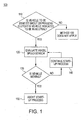
- Method 100 is executed if the operator attempts to start the vehicle, the vehicle is indicated as being in neutral by a gear shift sensor or other indicator and the operator does not depress the clutch (step 110). If these conditions are met, the ECU then evaluates an input signal from a wheel speed sensor (step 120).
- Wheel speed sensors are common in modem vehicles that include anti-lock braking systems (ABS). In an anti-lock braking system, the wheel speed sensors provide input relating to the rotational speed of a measured wheel, thus allowing the ABS to determine how to modify the vehicle's braking performance. In method 100, the wheel sensors also provide input regarding the rotational speed of a measured wheel.
- the ECU evaluates the received wheel speed signal and determines if the vehicle is moving or not by determining if the wheel speed is equal to zero (step 130). If the wheel speed is equal to zero (i.e., the vehicle is not moving) and the vehicle has been enabled to allow starting of the vehicle without depression of the clutch, then the ECU allows the vehicle to be started as long as the monitored wheel speed remains equal to zero (step 140). In other words, during the entirety of the vehicle start-up process, the ECU monitors the wheel speed of the vehicle and allows start-up to occur as long as the vehicle is not moving. If vehicle movement is detected (e.g., the monitored wheel speed is not equal to zero), the start-up process is aborted (step 150) and an error or problem is indicated to the driver.
- Method 100 performs two important functions relating to a vehicle's movement. Initially, method 100 ensures that the vehicle is not moving when start-up is initialized. Additionally, if the vehicle is in a false-neutral state at start-up, the start-up process will result in the engine engaging the vehicle's powertrain and the vehicle will begin to move. Thus, method 100 senses the movement of the vehicle and quickly shuts-down the start-up process before damage can occur.
- FIG. 2 illustrates an example timing diagram 200 resulting from an application of method 100.
- FIG. 2 illustrates the wheel speed over time of a vehicle in a false-neutral state.
- the vehicle is not moving.
- the output from the wheel sensors indicates that the vehicle wheel speed is zero.
- the vehicle is allowed to continue the start-up process.
- the vehicle begins to move forward (at time B).
- the vehicle's ECU senses the vehicle movement (step 140 in FIG. 1 ) and immediately shuts down the ignition process (at time C).
- the start-up process proceeds as normal until vehicle movement is detected. This means that the vehicle's engine actually does start in response to the vehicle's start-up process. At the moment that engine ignition occurs, the vehicle still is not moving and so the vehicle start-up process continues. However, as the engine begins to function, the vehicle's powertrain is engaged and the vehicle's wheels begin to move. Assuming that there is a short delay time between initial movement of the wheels and an indication by the vehicle's wheel sensors that the wheel is moving, the vehicle will move a short distance before the vehicle's ECU shuts down the start-up process.
- the engine of vehicle will be rotating at approximately 150 revolutions/minute (RPM).
- RPM revolutions/minute
- Experimental conditions indicate that engine shutdown could take an additional period of time (in one example, an additional 130 ms).
- the vehicle could move for a total of 330 ms before complete shutdown occurs.
- the wheels of the vehicle could have a wheel speed of up to 8 RPM (as illustrated in FIG. 2 ). Wheels rotating at a speed of 8 RPM for 330 ms will result in vehicle movement of approximately 4.2 inches. Therefore, while the method 100 does result in some movement of the vehicle before shutdown, the amount of vehicle movement is small and insignificant.
- method 100 also include a reduction in component cost for the vehicle. Because method 100 uses existing vehicle components and does not require any additional components (e.g., redundant neutral switches required by alternative solutions to the described problem), method 100 results in an overall cost reduction for the vehicle. Additionally, method 100 still allows a driver of the vehicle to start the vehicle in neutral without requiring depression of the vehicle's clutch, which some drivers prefer. Method 100 also results in a greatly reduced potential for serious safety issues arising from a neutral switch short circuit in the vehicle.
- Method 100 is of particular importance for a manual transmission engine with automatic on/off technology enabled.
- a vehicle operating with automatic on/off technology enabled may automatically turn off the vehicle's engine when the vehicle is not moving (e.g., has a vehicle speed of zero).
- the vehicle may automatically restart the engine.
- the vehicle may restart the engine.
- FIG. 3 reflects one such embodiment, illustrating a processor system 300 in a vehicle 10.
- the processor system 300 such as a computer system, generally comprises a central processing unit (CPU) 310, such as a microprocessor, a digital signal processor, or other programmable digital logic devices, which communicates with a sensor input 320 and an output device 325 over at least one bus 390.
- the processor system 300 includes a memory device 302, which stores instructions to be implemented by the CPU 310 such as those needed to implement method 100.
- the memory device 302 communicates with the CPU 310 over bus 390 typically through a memory controller.
- the memory device 302 communicates to the CPU 310 instructions that the CPU 310 is to regularly evaluate input samples from the sensor input 320 if the vehicle 10 is to be started without depression of the vehicle's clutch and if the vehicle is believed to be in neutral.
- the sensor input 320 is coupled to one or more wheel sensors 330 in the vehicle 10.
- the CPU 310 in accordance with method 100 evaluates the wheel speed input samples and if any vehicle movement is indicated, the CPU 310 outputs a signal through the output 325 that aborts the vehicle start-up process. Upon vehicle start-up termination, an alarm or other indication may be shown to the driver of the vehicle to indicate that a problem occurred.
- multiple CPUs 310 may be used in system 300, and the entire system 300 could be implemented as a system on a chip (SOC), through integrated circuits (ICs), or through other methods known in the art.
- SOC system on a chip
- ICs integrated circuits
Landscapes
- Engineering & Computer Science (AREA)
- Mechanical Engineering (AREA)
- Automation & Control Theory (AREA)
- Transportation (AREA)
- General Engineering & Computer Science (AREA)
- Control Of Transmission Device (AREA)
Description
- The technology herein relates generally to using existing vehicular sensors to determine non-sensed vehicular characteristics. More particularly, the technology herein relates to using a vehicle's wheel speed sensor to determine whether the vehicle is in a false-neutral state and to prevent unintended vehicle movement.
- A manual transmission vehicle can generally be started by an operator by depressing the vehicle's clutch while using the vehicle's ignition system. Most manual transmission vehicles may also be started without depressing the clutch if the vehicle's transmission is in neutral. In neutral, the transmission's gears are already disengaged and no harm should result to the vehicle if the vehicle is started without depressing the vehicle's clutch.
- However, a failure in one or more vehicle systems could cause the vehicle's electronic control unit (ECU) to falsely identify the vehicle as being in neutral. For example, a switch failure or an electrical short could result in the vehicle's ECU to report that the vehicle is in neutral when indeed the vehicle is actually in gear. In such a situation, the vehicle's ECU would allow an operator to attempt to start the vehicle without depressing the clutch. As a result, damage could occur to the car or the car could uncontrollably attempt to move since the vehicle is already in gear.
- In order to avoid this potential problem, vehicle manufacturers have either disabled the ability to start the vehicle without depressing the clutch or have added an additional switch to provided redundancy in the event of a switch failure. However, these solutions are not optimal as, on the one hand, the solution requires removal of a convenient operator feature of the vehicle, and on the other hand, the solution requires additional cost and complexity resulting from the need for additional components and control of those components.
- Therefore, an improved solution to the problem of ensuring that a vehicle is not started out of neutral when the vehicle's clutch is not depressed is desired.
- The closest
prior art DE 10 2005 015159 A1 discloses a method for recognizing the neutral position of a clutch and the ability to manipulate the clutch when errors occur. The reference is silent regarding the vehicle start-up process. - In various example embodiments, the technology described herein provides methods and systems for diagnosing whether a vehicle is in a false-neutral state and for preventing vehicle movement during start-up arising from a false-neutral indication. During a start-up process, a vehicle processor monitors signals output from one or more wheel speed sensors to determine whether the vehicle is moving. If vehicle movement is sensed, the start-up process is terminated in order to avoid unintended vehicle movement.
- In one example embodiment, the technology provides a method and system for preventing unintended vehicle movement arising from a false-neutral indication even when the vehicle's clutch is not depressed during a start-up process.
- There has thus been outlined, rather broadly, the features of the technology in order that the detailed description that follows may be better understood, and in order that the present contribution to the art may be better appreciated. There are additional features of the technology that will be described and which will form the subject matter of the claims. Additional aspects and advantages of the technology will be apparent from the following detailed description of an exemplary embodiment which is illustrated in the accompanying drawings. The technology is capable of other embodiments and of being practiced and earned out in various ways. Also, it is to be understood that the phraseology and terminology employed are for the purpose of description and should not be regarded as limiting.
- The technology is illustrated and described herein with reference to the various drawings, in which like reference numbers denote like method steps and/or system components, and in which:
-
FIG. 1 is a method of diagnosing a false-neutral state and preventing unintended vehicle movement, according to a disclosed embodiment; -
FIG. 2 is a timing diagram illustrating a method of preventing unintended vehicle movement arising from a false-neutral state, according to a disclosed embodiment; and -
FIG. 3 is a processor system, according to a disclosed embodiment. - Before describing the disclosed embodiments of the technology in detail, it is to be understood that the technology is not limited in its application to the details of the particular arrangement shown here since the technology is capable of other embodiments. Also, the terminology used herein is for the purpose of description and not of limitation.
- In various example embodiments, the technology described herein provides a method and system for diagnosing if a manual transmission vehicle is actually in a neutral state during the vehicle start-up process. Through the disclosed diagnosis system, unintended vehicle movement during the startup process is avoided. Other benefits and applications of the disclosed method and system are also contemplated herein, as will be obvious to those of ordinary skill in the art.
- In order to avoid unintentional or accidental starting of a manual transmission vehicle without depressing the vehicle's clutch, the vehicle's electronic control unit (ECU) may be modified to include instructions further limiting when the vehicle can be started. The instructions require input signals from vehicle sensors that are already incorporated in the vehicle and are used for other purposes. Therefore, no additional components are necessary in the disclosed solution.
- As illustrated in
FIG. 1 , when the ECU receives an indication that an operator is attempting to start the vehicle, the ECU executesmethod 100.Method 100 is executed if the operator attempts to start the vehicle, the vehicle is indicated as being in neutral by a gear shift sensor or other indicator and the operator does not depress the clutch (step 110). If these conditions are met, the ECU then evaluates an input signal from a wheel speed sensor (step 120). Wheel speed sensors are common in modem vehicles that include anti-lock braking systems (ABS). In an anti-lock braking system, the wheel speed sensors provide input relating to the rotational speed of a measured wheel, thus allowing the ABS to determine how to modify the vehicle's braking performance. Inmethod 100, the wheel sensors also provide input regarding the rotational speed of a measured wheel. The ECU evaluates the received wheel speed signal and determines if the vehicle is moving or not by determining if the wheel speed is equal to zero (step 130). If the wheel speed is equal to zero (i.e., the vehicle is not moving) and the vehicle has been enabled to allow starting of the vehicle without depression of the clutch, then the ECU allows the vehicle to be started as long as the monitored wheel speed remains equal to zero (step 140). In other words, during the entirety of the vehicle start-up process, the ECU monitors the wheel speed of the vehicle and allows start-up to occur as long as the vehicle is not moving. If vehicle movement is detected (e.g., the monitored wheel speed is not equal to zero), the start-up process is aborted (step 150) and an error or problem is indicated to the driver. -
Method 100 performs two important functions relating to a vehicle's movement. Initially,method 100 ensures that the vehicle is not moving when start-up is initialized. Additionally, if the vehicle is in a false-neutral state at start-up, the start-up process will result in the engine engaging the vehicle's powertrain and the vehicle will begin to move. Thus,method 100 senses the movement of the vehicle and quickly shuts-down the start-up process before damage can occur. -
FIG. 2 illustrates an example timing diagram 200 resulting from an application ofmethod 100.FIG. 2 illustrates the wheel speed over time of a vehicle in a false-neutral state. At time A when a start-up process begins, the vehicle is not moving. Thus, the output from the wheel sensors indicates that the vehicle wheel speed is zero. Assuming that the vehicle allows for start-up in neutral without the depression of the vehicle's clutch, the vehicle is allowed to continue the start-up process. However, because the vehicle is in a false-neutral state, once the start-up proceeds, the vehicle begins to move forward (at time B). The vehicle's ECU senses the vehicle movement (step 140 inFIG. 1 ) and immediately shuts down the ignition process (at time C). - In the example of
FIG. 2 , the start-up process proceeds as normal until vehicle movement is detected. This means that the vehicle's engine actually does start in response to the vehicle's start-up process. At the moment that engine ignition occurs, the vehicle still is not moving and so the vehicle start-up process continues. However, as the engine begins to function, the vehicle's powertrain is engaged and the vehicle's wheels begin to move. Assuming that there is a short delay time between initial movement of the wheels and an indication by the vehicle's wheel sensors that the wheel is moving, the vehicle will move a short distance before the vehicle's ECU shuts down the start-up process. For example, if the vehicle operates for 200 ms before the vehicle's wheel sensors indicate movement of the vehicle, then the engine of vehicle will be rotating at approximately 150 revolutions/minute (RPM). Experimental conditions indicate that engine shutdown could take an additional period of time (in one example, an additional 130 ms). Thus, in this example, the vehicle could move for a total of 330 ms before complete shutdown occurs. With an engine rotation of 150 RPM, the wheels of the vehicle could have a wheel speed of up to 8 RPM (as illustrated inFIG. 2 ). Wheels rotating at a speed of 8 RPM for 330 ms will result in vehicle movement of approximately 4.2 inches. Therefore, while themethod 100 does result in some movement of the vehicle before shutdown, the amount of vehicle movement is small and insignificant. - Advantages of using
method 100 also include a reduction in component cost for the vehicle. Becausemethod 100 uses existing vehicle components and does not require any additional components (e.g., redundant neutral switches required by alternative solutions to the described problem),method 100 results in an overall cost reduction for the vehicle. Additionally,method 100 still allows a driver of the vehicle to start the vehicle in neutral without requiring depression of the vehicle's clutch, which some drivers prefer.Method 100 also results in a greatly reduced potential for serious safety issues arising from a neutral switch short circuit in the vehicle. -
Method 100 is of particular importance for a manual transmission engine with automatic on/off technology enabled. For example, a vehicle operating with automatic on/off technology enabled may automatically turn off the vehicle's engine when the vehicle is not moving (e.g., has a vehicle speed of zero). Upon an appropriate input, however, the vehicle may automatically restart the engine. For example, in order to preserve the vehicle's battery life or to provide additional power for providing passenger comforts requiring energy (e.g., radio, air conditioning, etc.), the vehicle may restart the engine. In this scenario, it is imperative that thevehicle employ method 100 in order to protect against a false-neutral state. - While some aspects of the above disclosure necessarily relate to hardware in a vehicle, methods of applying the above-identified method may be implemented in either software or hardware.
FIG. 3 reflects one such embodiment, illustrating aprocessor system 300 in avehicle 10. Theprocessor system 300, such as a computer system, generally comprises a central processing unit (CPU) 310, such as a microprocessor, a digital signal processor, or other programmable digital logic devices, which communicates with asensor input 320 and anoutput device 325 over at least onebus 390. Theprocessor system 300 includes amemory device 302, which stores instructions to be implemented by theCPU 310 such as those needed to implementmethod 100. Thememory device 302 communicates with theCPU 310 overbus 390 typically through a memory controller. Thememory device 302 communicates to theCPU 310 instructions that theCPU 310 is to regularly evaluate input samples from thesensor input 320 if thevehicle 10 is to be started without depression of the vehicle's clutch and if the vehicle is believed to be in neutral. Thesensor input 320 is coupled to one ormore wheel sensors 330 in thevehicle 10. TheCPU 310 in accordance withmethod 100 evaluates the wheel speed input samples and if any vehicle movement is indicated, theCPU 310 outputs a signal through theoutput 325 that aborts the vehicle start-up process. Upon vehicle start-up termination, an alarm or other indication may be shown to the driver of the vehicle to indicate that a problem occurred. Of course,multiple CPUs 310 may be used insystem 300, and theentire system 300 could be implemented as a system on a chip (SOC), through integrated circuits (ICs), or through other methods known in the art.
Claims (14)
- A method of equipping a vehicle (10) to prevent unintended vehicle movement arising from a false-neutral indication for the vehicle, the method comprising:providing at least one wheel speed sensor (330) in the vehicle (10), the at least one wheel speed sensor (330) configured to output a plurality of wheel speed signals; and characterized bycoupling the at least one wheel speed sensor (330) with a processor (300) configured to process the plurality of wheel speed signals to determine whether the vehicle (10) is moving during a vehicle start-up process, the processor (300) further configured to output a termination signal if the vehicle (10) is determined to be moving during the vehicle start-up process; andcoupling the processor output (325) with a vehicle control system to shut-down the vehicle (10) upon receipt of the termination signal.
- The method of claim 1, further comprising providing a memory (302) for storing instructions to configure the processor..
- The method of claim 1, wherein the processor (300) is configured to determine whether the vehicle (10) is moving during the vehicle start-up process if the vehicle's clutch is not depressed and if the vehicle is indicated as being in a neutral state.
- The method of claim 1, wherein the vehicle control system is configured to shut-down the vehicle within a minimum amount of time required for the at least one wheel speed sensor (330) to detect movement, for the processor to receive at least one of the plurality of wheel speed signals, and for the vehicle control system to receive the termination signal.
- The method of claim 4, wherein the minimum amount of time is equal to or less than 330 ms.
- The method of claim 1, wherein the vehicle control system is configured to shut-down the vehicle (10) so as to minimize any vehicle movement resulting from the false-neutral indication.
- The method of claim 1, wherein the at least one wheel speed sensor (330) is provided as part of the vehicle's anti-lock braking system.
- A system to prevent unintended vehicle movement arising from a false-neutral indication for the vehicle (10), comprising;
at least one wheel speed sensor (330) in the vehicle (10) configured to output a plurality of wheel speed signals; and characterized by
a processor (300) coupled to the at least one wheel speed sensor (330) and configured to process the plurality of wheel speed signals to determine whether the vehicle (10) is moving during a vehicle start-up process, the processor (300) further configured to output a termination signal if it determines that the vehicles (10) moving during the vehicle start-up process; and
a vehicle control system coupled to the processor (300) and configured to shut-down the vehicle (10) upon receipt of the termination signal. - The system of claim 8, further comprising a memor (302) for storing instructions to configure the processor.
- The system of claim 8, wherein the processor (300) is configured to determine whether the vehicle (10) is moving during the vehicle start-up process if the vehicle's clutch is not depressed and if the vehicle is indicated as being in a neutral state.
- The system of claim 8, wherein the vehicle control system is configured to shut-down the vehicle within a minimum amount of time required for the at least one wheel speed sensor (330) to detect movement, for the processor to receive at least one of the plurality of wheel speed signals, and for the vehicle control system to receive the termination signal.
- The system of claim 11, wherein the minimum amount of time is equal to or less than 330 ms.
- The system of claim 8, wherein the vehicle control system is configured to shut-down the vehicle (10) so as to minimize any vehicle movement resulting from the false-neutral indication.
- The system of claim 8, wherein the at least one wheel speed sensor (330) is a part of the vehicle's anti-lock braking system.
Applications Claiming Priority (2)
| Application Number | Priority Date | Filing Date | Title |
|---|---|---|---|
| US12/685,165 US8386132B2 (en) | 2010-01-11 | 2010-01-11 | Manual transmission neutral switch diagnostic and movement prevention method and system |
| PCT/US2011/020439 WO2011085145A1 (en) | 2010-01-11 | 2011-01-07 | Manual transmission neutral switch diagnostic and movement prevention method and system for a vehicle |
Publications (2)
| Publication Number | Publication Date |
|---|---|
| EP2524154A1 EP2524154A1 (en) | 2012-11-21 |
| EP2524154B1 true EP2524154B1 (en) | 2016-11-23 |
Family
ID=43799573
Family Applications (1)
| Application Number | Title | Priority Date | Filing Date |
|---|---|---|---|
| EP11700586.8A Not-in-force EP2524154B1 (en) | 2010-01-11 | 2011-01-07 | Manual transmission neutral switch diagnostic and movement prevention method and system for a vehicle |
Country Status (4)
| Country | Link |
|---|---|
| US (1) | US8386132B2 (en) |
| EP (1) | EP2524154B1 (en) |
| CA (1) | CA2785102A1 (en) |
| WO (1) | WO2011085145A1 (en) |
Families Citing this family (6)
| Publication number | Priority date | Publication date | Assignee | Title |
|---|---|---|---|---|
| US20120303533A1 (en) | 2011-05-26 | 2012-11-29 | Michael Collins Pinkus | System and method for securing, distributing and enforcing for-hire vehicle operating parameters |
| US9037852B2 (en) * | 2011-09-02 | 2015-05-19 | Ivsc Ip Llc | System and method for independent control of for-hire vehicles |
| EP2781804B1 (en) * | 2011-11-18 | 2017-12-20 | JATCO Ltd | Device for controlling automatic transmission and method for controlling same |
| US20130253999A1 (en) | 2012-03-22 | 2013-09-26 | Frias Transportation Infrastructure Llc | Transaction and communication system and method for vendors and promoters |
| US10393083B2 (en) | 2017-05-25 | 2019-08-27 | Automotive Data Solutions, Inc. | System for remote starting of vehicle with manual transmission |
| JP7367397B2 (en) * | 2019-08-30 | 2023-10-24 | スズキ株式会社 | Engine starting control system |
Family Cites Families (8)
| Publication number | Priority date | Publication date | Assignee | Title |
|---|---|---|---|---|
| EP0324878A1 (en) * | 1988-01-20 | 1989-07-26 | Csepel Autogyár | Method and arrangement for gentle starting and fuel-saving parking of motor road vehicles equipped with an automatic hydromechanical transmission controlled electrohydraulically |
| DE10065023A1 (en) | 2000-12-23 | 2002-07-04 | Bosch Gmbh Robert | Automatic control system for transmission of motor vehicle uses computer to ensure that clutch is disengaged when engine starter is activated |
| US8746812B2 (en) * | 2004-10-08 | 2014-06-10 | Marcia Albright | Brake control unit |
| DE102005015159B4 (en) | 2005-04-02 | 2007-04-19 | Luk Lamellen Und Kupplungsbau Beteiligungs Kg | Prevent unwanted vehicle movement |
| DE102007013458A1 (en) | 2007-03-21 | 2007-12-06 | Daimlerchrysler Ag | Gear unit switching device for motor vehicle, has gearshift lever with two digital switches for detecting neutral-position of lever, where switches detect different gearshift level positions, which exceed allowable tolerance |
| JP4888440B2 (en) | 2008-06-03 | 2012-02-29 | トヨタ自動車株式会社 | Sensor abnormality diagnosis device |
| DE102008042256A1 (en) | 2008-09-22 | 2010-04-08 | Robert Bosch Gmbh | Method for diagnosing a functionality of a neutral-speed sensor |
| GB0822382D0 (en) | 2008-12-09 | 2009-01-14 | Ford Global Tech Llc | A method and apparatus for confirming the output from a sensor |
-
2010
- 2010-01-11 US US12/685,165 patent/US8386132B2/en active Active
-
2011
- 2011-01-07 CA CA2785102A patent/CA2785102A1/en not_active Abandoned
- 2011-01-07 WO PCT/US2011/020439 patent/WO2011085145A1/en not_active Ceased
- 2011-01-07 EP EP11700586.8A patent/EP2524154B1/en not_active Not-in-force
Also Published As
| Publication number | Publication date |
|---|---|
| US8386132B2 (en) | 2013-02-26 |
| US20110172884A1 (en) | 2011-07-14 |
| EP2524154A1 (en) | 2012-11-21 |
| WO2011085145A1 (en) | 2011-07-14 |
| CA2785102A1 (en) | 2011-07-14 |
Similar Documents
| Publication | Publication Date | Title |
|---|---|---|
| US7860636B2 (en) | Eco-run control device and engine restart method | |
| US10239531B2 (en) | Fault-tolerant automotive braking system | |
| US8386132B2 (en) | Manual transmission neutral switch diagnostic and movement prevention method and system | |
| JP5299375B2 (en) | Vehicle abnormality diagnosis device | |
| CN104442795A (en) | Method and device for monitoring a drive of a motor vehicle | |
| EP4023513B1 (en) | Vehicle start/stop control method and apparatus, vehicle, and electronic device | |
| CN106917866B (en) | Shift control method, device and vehicle for transmission | |
| CN110382923B (en) | Method of identifying missed engine stops and serviceability | |
| CN102485544A (en) | Torque sensor fault detection device and method | |
| US9393948B2 (en) | Vehicle start-up control mechanism | |
| US8457852B2 (en) | Device and method for preventing a motor vehicle engine from stopping in an automatic brake operation | |
| CN106043304B (en) | Method for preventing accidental acceleration of a motor vehicle | |
| CN118343147A (en) | Vehicle safety monitoring method, device, storage medium and vehicle | |
| CN107206981A (en) | Control unit and method for preventing unintentional vehicle movements | |
| KR20170070398A (en) | Engine control system of manual transmission vehicle for autonomous emergency braking | |
| CA2621042A1 (en) | Cruise control system having verification and/or notification features | |
| JP2024134937A (en) | Vehicle condition notification system and vehicle condition notification method | |
| US20100100273A1 (en) | Method and device for operating a motor vehicle | |
| CN110398684B (en) | Fault diagnosis method and system for automobile clutch switch and automobile | |
| KR20120079640A (en) | Fault diagnosis system for neutral switch and method thereof | |
| CN115626172A (en) | Motor safety monitoring system and method, vehicle and storage medium | |
| CN112810626B (en) | Vehicle control method, device and equipment | |
| JPH04240997A (en) | Control method for on-vehicle electronic device | |
| JP2014034912A (en) | Vehicle control device | |
| JP2021134708A (en) | Control device |
Legal Events
| Date | Code | Title | Description |
|---|---|---|---|
| PUAI | Public reference made under article 153(3) epc to a published international application that has entered the european phase |
Free format text: ORIGINAL CODE: 0009012 |
|
| 17P | Request for examination filed |
Effective date: 20120703 |
|
| AK | Designated contracting states |
Kind code of ref document: A1 Designated state(s): AL AT BE BG CH CY CZ DE DK EE ES FI FR GB GR HR HU IE IS IT LI LT LU LV MC MK MT NL NO PL PT RO RS SE SI SK SM TR |
|
| DAX | Request for extension of the european patent (deleted) | ||
| GRAP | Despatch of communication of intention to grant a patent |
Free format text: ORIGINAL CODE: EPIDOSNIGR1 |
|
| INTG | Intention to grant announced |
Effective date: 20160607 |
|
| GRAS | Grant fee paid |
Free format text: ORIGINAL CODE: EPIDOSNIGR3 |
|
| GRAA | (expected) grant |
Free format text: ORIGINAL CODE: 0009210 |
|
| RAP1 | Party data changed (applicant data changed or rights of an application transferred) |
Owner name: FCA US LLC |
|
| AK | Designated contracting states |
Kind code of ref document: B1 Designated state(s): AL AT BE BG CH CY CZ DE DK EE ES FI FR GB GR HR HU IE IS IT LI LT LU LV MC MK MT NL NO PL PT RO RS SE SI SK SM TR |
|
| REG | Reference to a national code |
Ref country code: GB Ref legal event code: FG4D |
|
| REG | Reference to a national code |
Ref country code: CH Ref legal event code: EP |
|
| REG | Reference to a national code |
Ref country code: IE Ref legal event code: FG4D |
|
| REG | Reference to a national code |
Ref country code: AT Ref legal event code: REF Ref document number: 848211 Country of ref document: AT Kind code of ref document: T Effective date: 20161215 |
|
| REG | Reference to a national code |
Ref country code: DE Ref legal event code: R096 Ref document number: 602011032654 Country of ref document: DE |
|
| REG | Reference to a national code |
Ref country code: FR Ref legal event code: PLFP Year of fee payment: 7 |
|
| PG25 | Lapsed in a contracting state [announced via postgrant information from national office to epo] |
Ref country code: LV Free format text: LAPSE BECAUSE OF FAILURE TO SUBMIT A TRANSLATION OF THE DESCRIPTION OR TO PAY THE FEE WITHIN THE PRESCRIBED TIME-LIMIT Effective date: 20161123 |
|
| REG | Reference to a national code |
Ref country code: LT Ref legal event code: MG4D |
|
| REG | Reference to a national code |
Ref country code: NL Ref legal event code: MP Effective date: 20161123 |
|
| REG | Reference to a national code |
Ref country code: AT Ref legal event code: MK05 Ref document number: 848211 Country of ref document: AT Kind code of ref document: T Effective date: 20161123 |
|
| PG25 | Lapsed in a contracting state [announced via postgrant information from national office to epo] |
Ref country code: GR Free format text: LAPSE BECAUSE OF FAILURE TO SUBMIT A TRANSLATION OF THE DESCRIPTION OR TO PAY THE FEE WITHIN THE PRESCRIBED TIME-LIMIT Effective date: 20170224 Ref country code: LT Free format text: LAPSE BECAUSE OF FAILURE TO SUBMIT A TRANSLATION OF THE DESCRIPTION OR TO PAY THE FEE WITHIN THE PRESCRIBED TIME-LIMIT Effective date: 20161123 Ref country code: SE Free format text: LAPSE BECAUSE OF FAILURE TO SUBMIT A TRANSLATION OF THE DESCRIPTION OR TO PAY THE FEE WITHIN THE PRESCRIBED TIME-LIMIT Effective date: 20161123 Ref country code: NL Free format text: LAPSE BECAUSE OF FAILURE TO SUBMIT A TRANSLATION OF THE DESCRIPTION OR TO PAY THE FEE WITHIN THE PRESCRIBED TIME-LIMIT Effective date: 20161123 Ref country code: NO Free format text: LAPSE BECAUSE OF FAILURE TO SUBMIT A TRANSLATION OF THE DESCRIPTION OR TO PAY THE FEE WITHIN THE PRESCRIBED TIME-LIMIT Effective date: 20170223 |
|
| PG25 | Lapsed in a contracting state [announced via postgrant information from national office to epo] |
Ref country code: AT Free format text: LAPSE BECAUSE OF FAILURE TO SUBMIT A TRANSLATION OF THE DESCRIPTION OR TO PAY THE FEE WITHIN THE PRESCRIBED TIME-LIMIT Effective date: 20161123 Ref country code: BE Free format text: LAPSE BECAUSE OF NON-PAYMENT OF DUE FEES Effective date: 20170131 Ref country code: PL Free format text: LAPSE BECAUSE OF FAILURE TO SUBMIT A TRANSLATION OF THE DESCRIPTION OR TO PAY THE FEE WITHIN THE PRESCRIBED TIME-LIMIT Effective date: 20161123 Ref country code: ES Free format text: LAPSE BECAUSE OF FAILURE TO SUBMIT A TRANSLATION OF THE DESCRIPTION OR TO PAY THE FEE WITHIN THE PRESCRIBED TIME-LIMIT Effective date: 20161123 Ref country code: RS Free format text: LAPSE BECAUSE OF FAILURE TO SUBMIT A TRANSLATION OF THE DESCRIPTION OR TO PAY THE FEE WITHIN THE PRESCRIBED TIME-LIMIT Effective date: 20161123 Ref country code: FI Free format text: LAPSE BECAUSE OF FAILURE TO SUBMIT A TRANSLATION OF THE DESCRIPTION OR TO PAY THE FEE WITHIN THE PRESCRIBED TIME-LIMIT Effective date: 20161123 Ref country code: PT Free format text: LAPSE BECAUSE OF FAILURE TO SUBMIT A TRANSLATION OF THE DESCRIPTION OR TO PAY THE FEE WITHIN THE PRESCRIBED TIME-LIMIT Effective date: 20170323 Ref country code: HR Free format text: LAPSE BECAUSE OF FAILURE TO SUBMIT A TRANSLATION OF THE DESCRIPTION OR TO PAY THE FEE WITHIN THE PRESCRIBED TIME-LIMIT Effective date: 20161123 |
|
| PG25 | Lapsed in a contracting state [announced via postgrant information from national office to epo] |
Ref country code: CZ Free format text: LAPSE BECAUSE OF FAILURE TO SUBMIT A TRANSLATION OF THE DESCRIPTION OR TO PAY THE FEE WITHIN THE PRESCRIBED TIME-LIMIT Effective date: 20161123 Ref country code: EE Free format text: LAPSE BECAUSE OF FAILURE TO SUBMIT A TRANSLATION OF THE DESCRIPTION OR TO PAY THE FEE WITHIN THE PRESCRIBED TIME-LIMIT Effective date: 20161123 Ref country code: SK Free format text: LAPSE BECAUSE OF FAILURE TO SUBMIT A TRANSLATION OF THE DESCRIPTION OR TO PAY THE FEE WITHIN THE PRESCRIBED TIME-LIMIT Effective date: 20161123 Ref country code: RO Free format text: LAPSE BECAUSE OF FAILURE TO SUBMIT A TRANSLATION OF THE DESCRIPTION OR TO PAY THE FEE WITHIN THE PRESCRIBED TIME-LIMIT Effective date: 20161123 Ref country code: DK Free format text: LAPSE BECAUSE OF FAILURE TO SUBMIT A TRANSLATION OF THE DESCRIPTION OR TO PAY THE FEE WITHIN THE PRESCRIBED TIME-LIMIT Effective date: 20161123 |
|
| REG | Reference to a national code |
Ref country code: DE Ref legal event code: R097 Ref document number: 602011032654 Country of ref document: DE |
|
| PG25 | Lapsed in a contracting state [announced via postgrant information from national office to epo] |
Ref country code: SM Free format text: LAPSE BECAUSE OF FAILURE TO SUBMIT A TRANSLATION OF THE DESCRIPTION OR TO PAY THE FEE WITHIN THE PRESCRIBED TIME-LIMIT Effective date: 20161123 Ref country code: BG Free format text: LAPSE BECAUSE OF FAILURE TO SUBMIT A TRANSLATION OF THE DESCRIPTION OR TO PAY THE FEE WITHIN THE PRESCRIBED TIME-LIMIT Effective date: 20170223 Ref country code: BE Free format text: LAPSE BECAUSE OF FAILURE TO SUBMIT A TRANSLATION OF THE DESCRIPTION OR TO PAY THE FEE WITHIN THE PRESCRIBED TIME-LIMIT Effective date: 20161123 |
|
| REG | Reference to a national code |
Ref country code: CH Ref legal event code: PL |
|
| PG25 | Lapsed in a contracting state [announced via postgrant information from national office to epo] |
Ref country code: MC Free format text: LAPSE BECAUSE OF FAILURE TO SUBMIT A TRANSLATION OF THE DESCRIPTION OR TO PAY THE FEE WITHIN THE PRESCRIBED TIME-LIMIT Effective date: 20161123 |
|
| PLBE | No opposition filed within time limit |
Free format text: ORIGINAL CODE: 0009261 |
|
| STAA | Information on the status of an ep patent application or granted ep patent |
Free format text: STATUS: NO OPPOSITION FILED WITHIN TIME LIMIT |
|
| PG25 | Lapsed in a contracting state [announced via postgrant information from national office to epo] |
Ref country code: LI Free format text: LAPSE BECAUSE OF NON-PAYMENT OF DUE FEES Effective date: 20170131 Ref country code: CH Free format text: LAPSE BECAUSE OF NON-PAYMENT OF DUE FEES Effective date: 20170131 |
|
| 26N | No opposition filed |
Effective date: 20170824 |
|
| REG | Reference to a national code |
Ref country code: IE Ref legal event code: MM4A |
|
| PG25 | Lapsed in a contracting state [announced via postgrant information from national office to epo] |
Ref country code: LU Free format text: LAPSE BECAUSE OF NON-PAYMENT OF DUE FEES Effective date: 20170107 Ref country code: SI Free format text: LAPSE BECAUSE OF FAILURE TO SUBMIT A TRANSLATION OF THE DESCRIPTION OR TO PAY THE FEE WITHIN THE PRESCRIBED TIME-LIMIT Effective date: 20161123 |
|
| REG | Reference to a national code |
Ref country code: FR Ref legal event code: PLFP Year of fee payment: 8 |
|
| PG25 | Lapsed in a contracting state [announced via postgrant information from national office to epo] |
Ref country code: IE Free format text: LAPSE BECAUSE OF NON-PAYMENT OF DUE FEES Effective date: 20170107 |
|
| PG25 | Lapsed in a contracting state [announced via postgrant information from national office to epo] |
Ref country code: MT Free format text: LAPSE BECAUSE OF NON-PAYMENT OF DUE FEES Effective date: 20170107 |
|
| PG25 | Lapsed in a contracting state [announced via postgrant information from national office to epo] |
Ref country code: HU Free format text: LAPSE BECAUSE OF FAILURE TO SUBMIT A TRANSLATION OF THE DESCRIPTION OR TO PAY THE FEE WITHIN THE PRESCRIBED TIME-LIMIT; INVALID AB INITIO Effective date: 20110107 |
|
| PG25 | Lapsed in a contracting state [announced via postgrant information from national office to epo] |
Ref country code: CY Free format text: LAPSE BECAUSE OF NON-PAYMENT OF DUE FEES Effective date: 20161123 |
|
| PG25 | Lapsed in a contracting state [announced via postgrant information from national office to epo] |
Ref country code: MK Free format text: LAPSE BECAUSE OF FAILURE TO SUBMIT A TRANSLATION OF THE DESCRIPTION OR TO PAY THE FEE WITHIN THE PRESCRIBED TIME-LIMIT Effective date: 20161123 |
|
| PG25 | Lapsed in a contracting state [announced via postgrant information from national office to epo] |
Ref country code: TR Free format text: LAPSE BECAUSE OF FAILURE TO SUBMIT A TRANSLATION OF THE DESCRIPTION OR TO PAY THE FEE WITHIN THE PRESCRIBED TIME-LIMIT Effective date: 20161123 |
|
| PG25 | Lapsed in a contracting state [announced via postgrant information from national office to epo] |
Ref country code: AL Free format text: LAPSE BECAUSE OF FAILURE TO SUBMIT A TRANSLATION OF THE DESCRIPTION OR TO PAY THE FEE WITHIN THE PRESCRIBED TIME-LIMIT Effective date: 20161123 Ref country code: IS Free format text: LAPSE BECAUSE OF FAILURE TO SUBMIT A TRANSLATION OF THE DESCRIPTION OR TO PAY THE FEE WITHIN THE PRESCRIBED TIME-LIMIT Effective date: 20170323 |
|
| PGFP | Annual fee paid to national office [announced via postgrant information from national office to epo] |
Ref country code: FR Payment date: 20210125 Year of fee payment: 11 Ref country code: IT Payment date: 20210122 Year of fee payment: 11 |
|
| PGFP | Annual fee paid to national office [announced via postgrant information from national office to epo] |
Ref country code: GB Payment date: 20210128 Year of fee payment: 11 Ref country code: DE Payment date: 20210127 Year of fee payment: 11 |
|
| REG | Reference to a national code |
Ref country code: DE Ref legal event code: R119 Ref document number: 602011032654 Country of ref document: DE |
|
| GBPC | Gb: european patent ceased through non-payment of renewal fee |
Effective date: 20220107 |
|
| PG25 | Lapsed in a contracting state [announced via postgrant information from national office to epo] |
Ref country code: GB Free format text: LAPSE BECAUSE OF NON-PAYMENT OF DUE FEES Effective date: 20220107 Ref country code: DE Free format text: LAPSE BECAUSE OF NON-PAYMENT OF DUE FEES Effective date: 20220802 |
|
| PG25 | Lapsed in a contracting state [announced via postgrant information from national office to epo] |
Ref country code: FR Free format text: LAPSE BECAUSE OF NON-PAYMENT OF DUE FEES Effective date: 20220131 |
|
| PG25 | Lapsed in a contracting state [announced via postgrant information from national office to epo] |
Ref country code: IT Free format text: LAPSE BECAUSE OF NON-PAYMENT OF DUE FEES Effective date: 20220107 |