EP2523061A1 - Überwachungssystem und Verfahren zur Überwachung von Maschinen damit - Google Patents
Überwachungssystem und Verfahren zur Überwachung von Maschinen damit Download PDFInfo
- Publication number
- EP2523061A1 EP2523061A1 EP12167703A EP12167703A EP2523061A1 EP 2523061 A1 EP2523061 A1 EP 2523061A1 EP 12167703 A EP12167703 A EP 12167703A EP 12167703 A EP12167703 A EP 12167703A EP 2523061 A1 EP2523061 A1 EP 2523061A1
- Authority
- EP
- European Patent Office
- Prior art keywords
- machine
- display assembly
- user
- data
- display
- Prior art date
- Legal status (The legal status is an assumption and is not a legal conclusion. Google has not performed a legal analysis and makes no representation as to the accuracy of the status listed.)
- Withdrawn
Links
Images


Classifications
-
- G—PHYSICS
- G07—CHECKING-DEVICES
- G07C—TIME OR ATTENDANCE REGISTERS; REGISTERING OR INDICATING THE WORKING OF MACHINES; GENERATING RANDOM NUMBERS; VOTING OR LOTTERY APPARATUS; ARRANGEMENTS, SYSTEMS OR APPARATUS FOR CHECKING NOT PROVIDED FOR ELSEWHERE
- G07C3/00—Registering or indicating the condition or the working of machines or other apparatus, other than vehicles
- G07C3/08—Registering or indicating the production of the machine either with or without registering working or idle time
-
- G—PHYSICS
- G05—CONTROLLING; REGULATING
- G05B—CONTROL OR REGULATING SYSTEMS IN GENERAL; FUNCTIONAL ELEMENTS OF SUCH SYSTEMS; MONITORING OR TESTING ARRANGEMENTS FOR SUCH SYSTEMS OR ELEMENTS
- G05B19/00—Programme-control systems
- G05B19/02—Programme-control systems electric
- G05B19/18—Numerical control [NC], i.e. automatically operating machines, in particular machine tools, e.g. in a manufacturing environment, so as to execute positioning, movement or co-ordinated operations by means of programme data in numerical form
- G05B19/406—Numerical control [NC], i.e. automatically operating machines, in particular machine tools, e.g. in a manufacturing environment, so as to execute positioning, movement or co-ordinated operations by means of programme data in numerical form characterised by monitoring or safety
- G05B19/4065—Monitoring tool breakage, life or condition
-
- G—PHYSICS
- G05—CONTROLLING; REGULATING
- G05B—CONTROL OR REGULATING SYSTEMS IN GENERAL; FUNCTIONAL ELEMENTS OF SUCH SYSTEMS; MONITORING OR TESTING ARRANGEMENTS FOR SUCH SYSTEMS OR ELEMENTS
- G05B23/00—Testing or monitoring of control systems or parts thereof
- G05B23/02—Electric testing or monitoring
- G05B23/0205—Electric testing or monitoring by means of a monitoring system capable of detecting and responding to faults
- G05B23/0259—Electric testing or monitoring by means of a monitoring system capable of detecting and responding to faults characterized by the response to fault detection
- G05B23/0267—Fault communication, e.g. human machine interface [HMI]
- G05B23/0272—Presentation of monitored results, e.g. selection of status reports to be displayed; Filtering information to the user
-
- G—PHYSICS
- G05—CONTROLLING; REGULATING
- G05B—CONTROL OR REGULATING SYSTEMS IN GENERAL; FUNCTIONAL ELEMENTS OF SUCH SYSTEMS; MONITORING OR TESTING ARRANGEMENTS FOR SUCH SYSTEMS OR ELEMENTS
- G05B2219/00—Program-control systems
- G05B2219/20—Pc systems
- G05B2219/26—Pc applications
- G05B2219/2619—Wind turbines
-
- G—PHYSICS
- G05—CONTROLLING; REGULATING
- G05B—CONTROL OR REGULATING SYSTEMS IN GENERAL; FUNCTIONAL ELEMENTS OF SUCH SYSTEMS; MONITORING OR TESTING ARRANGEMENTS FOR SUCH SYSTEMS OR ELEMENTS
- G05B2219/00—Program-control systems
- G05B2219/30—Nc systems
- G05B2219/32—Operator till task planning
- G05B2219/32014—Augmented reality assists operator in maintenance, repair, programming, assembly, use of head mounted display with 2-D 3-D display and voice feedback, voice and gesture command
-
- G—PHYSICS
- G05—CONTROLLING; REGULATING
- G05B—CONTROL OR REGULATING SYSTEMS IN GENERAL; FUNCTIONAL ELEMENTS OF SUCH SYSTEMS; MONITORING OR TESTING ARRANGEMENTS FOR SUCH SYSTEMS OR ELEMENTS
- G05B2219/00—Program-control systems
- G05B2219/30—Nc systems
- G05B2219/40—Robotics, robotics mapping to robotics vision
- G05B2219/40544—Detect proximity of object
-
- G—PHYSICS
- G05—CONTROLLING; REGULATING
- G05B—CONTROL OR REGULATING SYSTEMS IN GENERAL; FUNCTIONAL ELEMENTS OF SUCH SYSTEMS; MONITORING OR TESTING ARRANGEMENTS FOR SUCH SYSTEMS OR ELEMENTS
- G05B2223/00—Indexing scheme associated with group G05B23/00
- G05B2223/06—Remote monitoring
-
- Y—GENERAL TAGGING OF NEW TECHNOLOGICAL DEVELOPMENTS; GENERAL TAGGING OF CROSS-SECTIONAL TECHNOLOGIES SPANNING OVER SEVERAL SECTIONS OF THE IPC; TECHNICAL SUBJECTS COVERED BY FORMER USPC CROSS-REFERENCE ART COLLECTIONS [XRACs] AND DIGESTS
- Y02—TECHNOLOGIES OR APPLICATIONS FOR MITIGATION OR ADAPTATION AGAINST CLIMATE CHANGE
- Y02P—CLIMATE CHANGE MITIGATION TECHNOLOGIES IN THE PRODUCTION OR PROCESSING OF GOODS
- Y02P90/00—Enabling technologies with a potential contribution to greenhouse gas [GHG] emissions mitigation
- Y02P90/02—Total factory control, e.g. smart factories, flexible manufacturing systems [FMS] or integrated manufacturing systems [IMS]
Definitions
- the field of the invention relates generally to monitoring systems and, more particularly, to a monitoring system for use with systems and methods for use in monitoring machines within systems.
- one or more components may become damaged or worn over time.
- components such as bearings and gears, wear over time.
- Continued operation with a worn or damaged component may cause additional damage to other components and/or may lead to a premature failure of the component.
- At least some known machines may be monitored with a sensor and/or monitoring system.
- At least some known sensor systems position at least one sensor assembly in close proximity to the machine and/or component being monitored.
- Such sensor assemblies may perform, for example, proximity measurements of at least some of the components of the machine and/or the machine itself.
- a user may be unable to readily access data directly from the sensors.
- Such sensor systems have a central data base that may be accessible from a computing device, such as a personal computer ("PC"). There is little or no local display of the data at the machines and or sensor assemblies themselves. Even if there is a local display of the data at the machine and/or the sensor assembly, such display generally only includes real-time data and does not display historical data. Such sensor systems require the use of a PC to retrieve any data from each machine and/or sensor assembly.
- PC personal computer
- a monitoring system for use with a system.
- the monitoring system includes a data management system that includes a database configured to store data representative of at least one operating characteristic of at least one machine.
- a portable display assembly is coupled to the data management system and includes at least one sensor configured to detect the presence of the machine within a predefined distance from a portion of the display assembly.
- the display assembly also includes a communication interface that is coupled to the data management system and is configured to receive the data.
- the display assembly includes a display media that is coupled to the communication interface for presenting an output representative of the data to a user of the display assembly such that the user is enabled to view historical data of the machine and/or monitor the machine in real-time.
- a system in another embodiment, includes at least one machine and a monitoring system that is coupled to the machine.
- the monitoring system includes a data management system that includes a database configured to store data representative of at least one operating characteristic of the machine.
- a portable display assembly is coupled to the data management system and includes at least one sensor configured to detect the presence of the machine within a predefined distance from a portion of the display assembly.
- the display assembly also includes a communication interface that is coupled to the data management system and is configured to receive the data.
- the display assembly includes a display media that is coupled to the communication interface for presenting an output representative of the data to a user of the display assembly such that the user is enabled to view historical data of the machine and/or monitor the machine in real-time.
- a method for use in monitoring machines is provided.
- the presence of at least one machine from within a predefined distance is detected.
- Data representative of at least one operating characteristic of the machine is received from a database.
- an output representative of the data is presented, via a display media, to a user of a display assembly such that the user is enabled to view historical data of the machine and/or monitor the machine in real-time.
- the example systems and methods described herein provide a monitoring system that enables a user to monitor a machine and retrieve real-time and historical data for the machine without the use of a personal computer.
- the embodiments described herein provide a monitoring system that includes a data management system that includes a database configured to store data representative of at least one operating characteristic of at least one machine.
- a portable display assembly is coupled to the data management system and includes at least one sensor configured to detect the presence of the machine within a predefmed distance from a portion of the display assembly.
- the display assembly also includes a communication interface that is coupled to the data management system and is configured to receive the data.
- the display assembly includes a display media that is coupled to the communication interface for presenting an output representative of the data to a user of the display assembly such that the user is enabled to view historical data of the machine and/or monitor the machine in real-time.
- the user may retrieve data, including historical data, directly from a database, and the use of a personal computer to retrieve the data from the machine may be negated.
- Fig. 1 illustrates a system 100, such as but not limited to an industrial facility or a power generation system.
- system 100 includes at least one machine 102, such as, but not limited to a wind turbine, a hydroelectric generator, a steam turbine, a gas turbine, and/or a compressor.
- machine 102 rotates a drive shaft 104 coupled to a load 106, such as a generator.
- load 106 such as a generator.
- the term "couple" is not limited to a direct mechanical, communication, and/or an electrical connection between components, but may also include an indirect mechanical, communication, and/or electrical connection between multiple components.
- the present invention is not limited to power generation systems, and one of ordinary skill in the art will appreciate that the current invention may be used in connection with any system that may contain machines.
- drive shaft 104 is at least partially supported by one or more bearings (not shown) housed within machine 102 and/or within load 106.
- the bearings may be housed within a separate support structure 108, such as a gearbox, or any other structure that enables system 100 to function as described herein.
- system 100 includes a monitoring system 101 that includes at least one sensor assembly 110 that measures and/or monitors at least one operating condition of machine 102, drive shaft 104, load 106, and/or of any other component that enables system 100 to function as described herein.
- sensor assembly 110 is a proximity sensor assembly that is positioned in close proximity to machine 102 for use in measuring and/or monitoring a distance 120 between machine 102 and sensor assembly 110.
- sensor assembly 110 uses one or more microwave signals to measure a proximity, such as a static and/or vibration proximity, of machine 102 with respect to sensor assembly 110.
- sensor assembly 110 may be used to measure and/or monitor any other component of system 100, and/or may be any other sensor or transducer assembly that enables system 100 to function as described herein.
- sensor assembly 110 is positioned in any relative location within system 100.
- a communication module 122 is coupled to sensor assembly 110.
- communication module 122 may be coupled to machine 102.
- communication module 122 enables sensor assembly 110 to communicate with at least one other component of system 100 and/or monitoring system 101.
- monitoring system 101 also includes a data management system 123 that is coupled to sensor assembly 110 via communication module 122.
- data management system 123 includes a database 124 that stores data therein, such as at least one operating condition of machine 102.
- data management system 123 is coupled to a display assembly 128 via a network 134.
- Data management system 123 may be any device capable of accessing network 134 including, without limitation, a desktop computer, a laptop computer, or other web-based connectable equipment.
- data management system 123 communicates with display assembly 128 using a wireless communication means, such as radio frequency (RF), e.g., FM radio and/or digital audio broadcasting, an Institute of Electrical and Electronics Engineers (IEEE®) 802.11 standard (e.g., 802.11(g) or 802.11(n)), the Worldwide Interoperability for Microwave Access (WIMAX®) standard, a cellular phone technology (e.g., the Global Standard for Mobile communication (GSM)), a satellite communication link, and/or any other suitable communication means.
- RF radio frequency
- IEEE® 802.11 standard e.g., 802.11(g) or 802.11(n)
- WiX® Worldwide Interoperability for Microwave Access
- GSM Global Standard for Mobile communication
- GSM Global Standard for Mobile communication
- satellite communication link e.g., Global Standard for Mobile communication
- data management system 123 may communicate with display assembly 128 using a wired network connection (e.g., Ethernet or an optical fiber).
- a wired network connection e.g., Ethernet or an optical fiber.
- microwave refers to a signal or a component that receives and/or transmits signals having frequencies between about 300 Megahertz (MHz) and to about 300 Gigahertz (GHz).
- communication module 122 enables sensor assembly 110 to communicate with data management system 123. More specifically, in the example embodiment, communication module 122 enables sensor assembly 110 to transmit data representative of at least one operating characteristic of machine 102 detected by sensor assembly 110 to data management system 123, wherein the data may be stored in database 124. In the example embodiment, the data may include a static and/or a vibration proximity measurement of machine 102 with respect to sensor assembly 110.
- display assembly 128 enables a user to retrieve the data directly from database 124. More specifically, in the example embodiment, display assembly 128 receives data and presents an output representative of the data to the user such that the user is enabled to view historical data and/or monitor machine 102 in real-time. In the example embodiment, display assembly 128 is positioned against the body of the user such that display assembly 128 is movable with the user. For example, display assembly 128 may be worn by the user or held by the user. Alternatively, display assembly 128 may be positioned in any other location with respect to the user.
- sensor assembly 110 measures and/or monitors the proximity, such as the static and/or vibration proximity, and/or the relative position of machine 102 with respect to sensor assembly 110 and transmits data representative of at least one operating characteristic of machine 102 to data management system 123, wherein the data is stored in database 124. The data may be transmitted to display assembly 128, wherein the data is then presented to the user to enable the user to view historical data and/or monitor machine 102 in real-time.
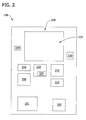
- Fig. 2 is a block diagram of display assembly 128 that may be used with system 100 (shown in Fig. 1 ).
- display assembly 128 is held or retained by a user such that display assembly 128 is positioned adjacent to the body of the user and enables display assembly 128 to be movable with the user.
- display assembly 128 is a handheld computing device, such as a smart phone.
- display assembly 128 may be any device that enables display assembly 128 to be positioned adjacent to the body of the user such that display assembly 128 is movable with the user, and that enables display assembly 128, monitoring system 101 (shown in Fig. 1 ), and/or system 100 to function as described herein.
- display assembly 128 includes a battery 201 that provides power to display assembly 128.
- battery 201 is a rechargeable lithium-ion battery 201.
- battery 201 may be any other lithium-based battery or any other type of battery that enables display assembly 128 and/or system 100 to function as described herein.
- display assembly 128 includes a communication interface 202 configured to receive at least one operating characteristic of machine 102 (shown in Fig. 1 ) from database 124 110 (shown in Fig. 1 ) within data management system 123 (shown in Fig. 1 ). More specifically, data management system 123 is coupled to communication interface 202 via network 134 (shown in Fig. 1 ).
- communication interface 202 is coupled to a short-range wireless communication channel (not shown), such as BLUETOOTH®. BLUETOOTH is a registered trademark of Bluetooth SIG, Inc. of Kirkland, Washington.
- communication interface 202 may be any other type of communication module that enables display assembly 128, system 101, and/or system 100 to function as described herein.
- display assembly 128 also includes a processor 210 that is coupled to communication interface 202 via a system bus (not shown). Processor 210 is also coupled to a memory device 214 via the system bus. Moreover, in the example embodiment, data assembly 128 includes an image capturing device 216 is coupled to processor 210 via the system bus and is configured to capture at least one image of machine 102 and/or system 100. In the example embodiment, device 216 is a camera. Alternatively, device 216 may be any other device that is configured to capture at least one image and that enables display assembly 128 and/or system 100 to function as described herein.
- executable instructions are stored in memory device 214.
- display assembly 128 is programmable to perform one or more operations described herein by programming processor 210.
- processor 210 may be programmed by encoding an operation as one or more executable instructions and providing the executable instructions in memory device 214.
- Processor 210 may include one or more processing units (e.g., in a multi-core configuration).
- processor 210 is programmed to generate at least one output based on the data that processor 210 receives from database 124. More specifically, in the example embodiment, processor 210 is programmed to generate a graphical and/or a textual representation of the data. Alternatively, processor 210 may be programmed to generate any other output that enables display assembly 128 and/or system 100 to function as described herein.
- processor refers generally to any programmable system including systems and microcontrollers, reduced instruction set circuits (RISC), application specific integrated circuits (ASIC), programmable logic circuits (PLC), and any other circuit or processor capable of executing the functions described herein.
- RISC reduced instruction set circuits
- ASIC application specific integrated circuits
- PLC programmable logic circuits
- processor 210 may include, but is not limited to, a general purpose central processing unit (CPU), a graphics processing unit (GPU), a microcontroller, a reduced instruction set computer (RISC) processor, an application specific integrated circuit (ASIC), a programmable logic circuit (PLC), and/or any other circuit or processor capable of executing the functions described herein.
- the methods described herein may be encoded as executable instructions embodied in a computer readable medium, including, without limitation, a storage device and/or a memory device. Such instructions, when executed by processor 210, cause processor 210 to perform at least a portion of the methods described herein.
- the above represent examples only, and thus are not intended to limit in any way the definition and/or meaning of the term processor.
- Memory device 214 enables information such as executable instructions and/or other data to be stored and retrieved.
- Memory device 214 may include one or more computer readable media, such as, without limitation, dynamic random access memory (DRAM), static random access memory (SRAM), a solid state disk, and/or a hard disk.
- Memory device 214 may be configured to store, without limitation, executable instructions, configuration data, geographic data (e.g., topography data and/or obstructions), utility network equipment data, and/or any other type of data.
- memory device 214 stores the data received from database 124 and stores the output generated by processor 210. Moreover, in the example embodiment, memory device 214 stores the image(s) captured by image capturing device 216. Memory device 214 is also configured to store other information related to system 100, such as the number of machines 102 and other components within system 100, and the locations of machines 102 and components within system 100. Moreover, in the example embodiment, memory device 214 may include random access memory (RAM), which can include non-volatile RAM (NVRAM), magnetic RAM (MRAM), ferroelectric RAM (FeRAM) and other forms of memory. Memory device 214 may also include read only memory (ROM), flash memory and/or Electrically Erasable Programmable Read Only Memory (EEPROM).
- RAM random access memory
- ROM read only memory
- EEPROM Electrically Erasable Programmable Read Only Memory
- Memory device 214 may also be, or include, a detachable or removable memory, including, but not limited to, a suitable cartridge, disk, CD ROM, DVD or USB memory.
- memory device 214 may be a database.
- database refers generally to any collection of data including hierarchical databases, relational databases, flat file databases, object-relational databases, object oriented databases, and any other structured collection of records or data that is stored in a computer system. The above represent examples only, and thus are not intended to limit in any way the definition and/or meaning of the term database.
- databases include, but are not limited to only including, Oracle® Database, MySQL, IBM® DB2, Microsoft® SQL Server, Sybase®, and PostgreSQL. However, any database may be used that enables the systems and methods described herein.
- Oracle is a registered trademark of Oracle Corporation, Redwood Shores, California
- IBM is a registered trademark of International Business Machines Corporation, Armonk, New York
- Microsoft is a registered trademark of Microsoft Corporation, Redmond, Washington
- Sybase is a registered trademark of Sybase, Dublin, California.
- a display media 218 and a display adaptor 220 are also coupled to processor 210 via the system bus.
- display media 218 includes a screen 224.
- display media 218 presents the output generated by processor 210 to the user via screen 224.
- display media 218 includes a visual display, such as a cathode ray tube (CRT), a liquid crystal display (LCD), an organic LED (OLED) display, and/or an "electronic ink" display.
- CTR cathode ray tube
- LCD liquid crystal display
- OLED organic LED
- the user is enabled to see the output on screen 224.
- display assembly 128 also includes a user interface 230 that is coupled to processor 210 via the system bus.
- User interface 230 receives any information suitable for use with the methods described herein. More specifically, in the example embodiment, the user can input the output the user would like displayed on display media 218.
- user interface 230 includes a keyboard 234.
- user may include, for example, a pointing device, a mouse, a stylus, a touch pad, a touch screen, a gyroscope, an accelerometer, a position detector.
- Display assembly 128 also includes at least one sensor 240 coupled to processor 210 via the system bus.
- sensor 240 is configured to detect the presence of machine 102 within a predefined distance 241 (shown in Fig. 1 ) from a portion of display assembly 128 such that the user is enabled to identify the location of machine 102 with respect to display assembly 128 and/or the user.
- sensor 240 is at least one of a global positioning system, a tilt sensor, and a compass.
- the user holding display assembly 128 moves adjacent to machine 102 and/or specifically, within distance 241.
- Sensor 240 detects the presence of machine 102 and transmits a signal representative of the detection to communication interface 202.
- the signal is transmitted to processor 210 and an output is generated and displayed via display media 218.
- the output enables the user to identify the location of machine 102 with respect to display assembly 128 and/or the user.
- data representative of at least one operating characteristic of machine 102 is transmitted from database 124 to communication interface 202 via network 134.
- Communication interface 202 transmits the data to processor 210 and to memory device 214 such that the data may be stored.
- Processor 210 generates at least one output based on the data received. More specifically, processor 210 generates an output that includes a graphical and/or textual representation of the data.
- Display media 218 then displays the output to the user via screen 224 such that the user is enabled to monitor machine 102.
- the user may retrieve historical data saved in memory device 214 and/or database 124 by requesting historical data via user interface 230.
- processor 210 When processor 210 receives such a request, processor 210 generates an output that includes a graphical and/or textual representation of the historical data that processor 210 receives from memory device 214 and/or database 124. The output of the historical data is transmitted to display media 218 for display to the user.
- the user may capture at least one image of machine 102 via image capturing device 216.
- the user may be enabled to identify machine 102 based on information related to system 100 stored in memory device, such as the number of machines 102 and other components within system 100, and the locations of machines 102 and other components within system 100.
- the image may also be presented to the user via display media 218.
- the output representative of the data received from database 124 may be superimposed upon the image.
- Fig. 3 illustrates an alternative display assembly 300 that may be used with system 100 (shown in Fig. 1 ) in place of display assembly 128 (shown in Figs. 1 and 2 ).
- display assembly 300 is worn by a user such that display assembly 300 is positioned adjacent to the body of the user and is movable with the user. More specifically, in the example embodiment, display assembly 300 is a pair of eyeglasses worn on the face of the user.
- display assembly 300 may be any device that enables display assembly 300 to be positioned adjacent to the body of the user such that display assembly 300 is movable with the user, and that enables display assembly 300, monitoring system 101, and system 100 to function as described herein.
- display assembly 300 includes a battery 301 that provides power to display assembly 300.
- battery 301 is a rechargeable lithium-ion battery 301.
- battery 301 may be any other lithium-based battery or any other type of battery that enables display assembly 300 to function as described herein.
- display assembly 300 includes a communication interface 302 configured to receive at least one operating characteristic of machine 102 (shown in Fig. 1 ) from database 124 (shown in Fig. 1 ) within data management system 123. More specifically, data management system 123 is coupled to communication interface 302 via network 134 (shown in Fig. 1 ). In the example embodiment, database 124 transmits the data to communication interface 302. Moreover, in the example embodiment, communication interface 302 is a wireless antenna. Alternatively, communication interface 302 may be any other type of communication module that enables display assembly 300 and/or system 100 to function as described herein.
- display assembly 300 also includes a processor 310 that is coupled to communication interface 302 via a system bus (not shown). Processor 310 is also coupled to a memory device 314 via the system bus. Moreover, in the example embodiment, data assembly 300 includes an image capturing device 316 is coupled to processor 310 via the system bus and is configured to capture at least one image of machine 102 and/or system 100. In the example embodiment, device 316 is an infrared camera. Alternatively, device 316 may be any other device configured to capture at least one image and that enables display assembly 300 and/or system 100 to function as described herein.
- executable instructions are stored in memory device 314.
- display assembly 300 is programmable to perform one or more operations described herein by programming processor 310.
- processor 310 may be programmed by encoding an operation as one or more executable instructions and providing the executable instructions in memory device 314.
- Processor 310 may include one or more processing units (e.g., in a multi-core configuration).
- processor 310 is programmed to generate at least one output based on the data that processor 310 receives from database 124. More specifically, in the example embodiment, processor 310 is programmed to generate a graphical and/or textual representation of the data.
- processor 310 may be programmed to generate any other output that enables display assembly 300 and/or system 100 to function as described herein.
- processor 310 may include, but is not limited to, a general purpose central processing unit (CPU), a graphics processing unit (GPU), a microcontroller, a reduced instruction set computer (RISC) processor, an application specific integrated circuit (ASIC), a programmable logic circuit (PLC), and/or any other circuit or processor capable of executing the functions described herein.
- the methods described herein may be encoded as executable instructions embodied in a computer readable medium, including, without limitation, a storage device and/or a memory device. Such instructions, when executed by processor 310, cause processor 310 to perform at least a portion of the methods described herein.
- the above represent examples only, and thus are not intended to limit in any way the definition and/or meaning of the term processor.
- Memory device 314 enables information such as executable instructions and/or other data to be stored and retrieved.
- Memory device 314 may include one or more computer readable media, such as, without limitation, dynamic random access memory (DRAM), static random access memory (SRAM), a solid state disk, and/or a hard disk.
- Memory device 314 may be configured to store, without limitation, executable instructions, configuration data, geographic data (e.g., topography data and/or obstructions), utility network equipment data, and/or any other type of data.
- memory device 314 stores the data received from database 124 and stores the output generated by processor 310. Moreover, in the example embodiment, memory device 314 stores the image(s) captured by image capturing device 316. Memory device 314 is also configured to store other information related to system 100, such as the number of machines 102 and other components within system 100, and the various locations of machines 102 and components within system 100. Moreover, in the example embodiment, memory device 314 may include random access memory (RAM), which can include non-volatile RAM (NVRAM), magnetic RAM (MRAM), ferroelectric RAM (FeRAM) and other forms of memory. Memory device 314 may also include read only memory (ROM), flash memory and/or Electrically Erasable Programmable Read Only Memory (EEPROM).
- RAM random access memory
- ROM read only memory
- EEPROM Electrically Erasable Programmable Read Only Memory
- Memory device 314 may also be, or include, a detachable or removable memory, including, but not limited to, a suitable cartridge, disk, CD ROM, DVD or USB memory.
- memory device 314 may be a database.
- database refers generally to any collection of data including hierarchical databases, relational databases, flat file databases, object-relational databases, object oriented databases, and any other structured collection of records or data that is stored in a computer system. The above represent examples only, and thus are not intended to limit in any way the definition and/or meaning of the term database.
- databases include, but are not limited to only including, Oracle® Database, MySQL, IBM® DB2, Microsoft® SQL Server, Sybase®, and PostgreSQL. However, any database may be used that enables the systems and methods described herein.
- Oracle is a registered trademark of Oracle Corporation, Redwood Shores, California
- IBM is a registered trademark of International Business Machines Corporation, Armonk, New York
- Microsoft is a registered trademark of Microsoft Corporation, Redmond, Washington
- Sybase is a registered trademark of Sybase, Dublin, California.
- a display media 318 and a display adaptor 320 are also coupled to processor 310 via the system bus.
- display media 318 includes at least one screen 323 within at least one lens 324. More specifically, in the example embodiment, display media 318 includes two lenses 324, wherein each lens 324 includes one screen 323.
- lenses 324 are polarizing lenses. Alternatively, lenses 324 may be any type of lens that enables display media 318 to function as described herein.
- display media 318 presents the output generated by processor 310 to the user via at least one lens 324.
- display media 318 includes a visual display, such as a cathode ray tube (CRT), a liquid crystal display (LCD), an organic LED (OLED) display, and/or an "electronic ink” display.
- a visual display such as a cathode ray tube (CRT), a liquid crystal display (LCD), an organic LED (OLED) display, and/or an "electronic ink” display.
- CTR cathode ray tube
- LCD liquid crystal display
- OLED organic LED
- the user is enabled to see the images on at least one of the lenses 324.
- display assembly 300 also includes a user interface 330 that is coupled to processor 310 via the system bus.
- User interface 330 receives any information suitable for use with the methods described herein. More specifically, in the example embodiment, the user can input the output the user would like displayed on display media 318. Further, in the example embodiment, user interface 330 includes a touch sensitive panel 334. Alternatively, user may include, for example, a keyboard, a pointing device, a mouse, a stylus, a touch pad, a touch screen, a gyroscope, an accelerometer, a position detector.
- Display assembly 300 also includes at least one sensor 340 coupled to processor 310 via the system bus.
- sensor 340 is configured to detect the presence of machine 102 within a distance 241 (shown in Fig. 1 ) from display assembly 300 such that the user is enabled to identify the location of machine 102 with respect to display assembly 300 and/or the user.
- sensor 340 is at least one of a global positioning system, a tilt sensor, and a compass.
- the user wearing display assembly 300 moves adjacent to machine 102 and/or, more specifically, within predefined distance 241.
- Sensor 340 detects the presence of machine 102 and sends a signal representative of the detection to communication interface 302. The signal is sent to processor 310 and an output is generated and presented via display media 318 such that the user is enabled to identify the location of machine 102 with respect to a portion of display assembly 300 and/or the user.
- data representative of at least one operating characteristic of machine 102 is transmitted from database 124 to communication interface 302.
- Communication interface 302 transmits the data to processor 310 and then to memory device 314 such that the data may be stored.
- Processor 310 generates at least one output based on the data received. More specifically, processor 310 generates an output that includes a graphical and/or textual representation of the data.
- Display media 318 then presents the output via at least one screen 323 within lens 324 to the user such that the user is enabled to monitor machine 102.
- the user may retrieve historical data saved in memory device 314 and/or database 124 by requesting historical data via user interface 330.
- processor 310 When processor 310 receives such a request, processor 310 generates an output that includes a graphical and/or textual representation of the historical data that processor 310 receives from memory device 314 and/or database 124. The output of the historical data is transmitted to display media 318 for display to the user.
- the user may capture at least one image of machine 102 via image capturing device 316.
- the user is enabled to identify machine 102 based on information related to system 100 stored in memory device 314, such as the number of machines 102 and other components within system 100, and the locations of machines 102 and components within system 100.
- the image may also be presented to the user via display media 318.
- the output representative of the data received from sensor assembly 110 may be superimposed upon the image.
- Fig. 4 is a flow chart that illustrates an example method 400 to monitor machines using a display assembly, such as display assembly 128 (shown in Figs. 1 and 2 ).
- Display assembly 128 is positioned 401 against the body of a user such that display assembly is movable with the user.
- the presence of at least one machine 102 (shown in Fig. 1 ) is detected 402 from within a predefined distance 241 (shown in Fig. 1 ) from display assembly 128.
- Method 400 also includes receiving 404 data representative of at least one operating characteristic of machine 102 from a database (shown in Fig. 1 ).
- a display media 218 (shown in Fig.
- FIG. 2 presents 406 an output representative of the data to the user of display assembly 128 such that the user is enabled to view historical data and/or monitor machine 102.
- at least one image of machine 102 is captured 408 to enable the user to identify machine 102 based on the image.
- the output may be superimposed 410 upon any captured image.
- the above-described embodiments of systems and methods enable a user to directly retrieve information related to at least one operating characteristic of at least one machine without the use of a personal computer. More specifically, the embodiments described herein provide a monitoring system that includes a data management system that includes a database configured to store data representative of at least one operating characteristic of at least one machine.
- a portable display assembly is coupled to the data management system and includes at least one sensor configured to detect the presence of the machine within a predefined distance from a portion of the display assembly.
- the display assembly also includes a communication interface that is coupled to the data management system and is configured to receive the data.
- the display assembly includes a display media that is coupled to the communication interface for presenting an output representative of the data to a user of the display assembly such that the user is enabled to view historical data of the machine and/or monitor the machine in real-time. Accordingly, the user is enabled to retrieve the data directly from a database and the use of a personal computer to retrieve the data from the machine may be negated.
- Technical features of the systems and methods described herein includes at least one of (a) detecting the presence of at least one machine from within a predefined distance; (b) receiving data representative of at least one operating characteristic of at least one machine from a database; and (c) presenting via a display media an output representative of data to a user of a display assembly such that the user is enabled to at least one of view historical data of at least one machine and monitor the at least one machine in real-time.
- Example embodiments of a system and a method for use in monitoring machines are described above in detail.
- the system and method are not limited to the specific embodiments described herein, but rather, components of the apparatus and/or steps of the method may be utilized independently and separately from other components and/or steps described herein.
- the system may also be used in combination with other systems and methods, and is not limited to practice with only the system as described herein. Rather, the example embodiment can be implemented and utilized in connection with many other applications.
Landscapes
- Engineering & Computer Science (AREA)
- Physics & Mathematics (AREA)
- General Physics & Mathematics (AREA)
- Human Computer Interaction (AREA)
- Automation & Control Theory (AREA)
- Manufacturing & Machinery (AREA)
- Testing And Monitoring For Control Systems (AREA)
- User Interface Of Digital Computer (AREA)
Applications Claiming Priority (1)
| Application Number | Priority Date | Filing Date | Title |
|---|---|---|---|
| US13/107,725 US8686871B2 (en) | 2011-05-13 | 2011-05-13 | Monitoring system and methods for monitoring machines with same |
Publications (1)
| Publication Number | Publication Date |
|---|---|
| EP2523061A1 true EP2523061A1 (de) | 2012-11-14 |
Family
ID=46396991
Family Applications (1)
| Application Number | Title | Priority Date | Filing Date |
|---|---|---|---|
| EP12167703A Withdrawn EP2523061A1 (de) | 2011-05-13 | 2012-05-11 | Überwachungssystem und Verfahren zur Überwachung von Maschinen damit |
Country Status (4)
| Country | Link |
|---|---|
| US (1) | US8686871B2 (de) |
| EP (1) | EP2523061A1 (de) |
| JP (1) | JP2012243314A (de) |
| CN (1) | CN102840877A (de) |
Cited By (3)
| Publication number | Priority date | Publication date | Assignee | Title |
|---|---|---|---|---|
| DE102015201290A1 (de) | 2015-01-26 | 2016-07-28 | Prüftechnik Dieter Busch AG | Positionieren zweier Körper mittels eines Ausrichtsystems mit einer Datenbrille |
| DE102015207134A1 (de) | 2015-04-20 | 2016-10-20 | Prüftechnik Dieter Busch AG | Verfahren zum Erfassen von Vibrationen einer Vorrichtung und Vibrationserfassungssystem |
| DE102015012077A1 (de) * | 2015-09-22 | 2017-03-23 | Prüftechnik Dieter Busch Aktiengesellschaft | Verfahren zum fluchtenden Ausrichten senkrechter Drehachsen drehbar gelagerter Körper und System zur Verwendung in einem solchen Verfahren |
Families Citing this family (18)
| Publication number | Priority date | Publication date | Assignee | Title |
|---|---|---|---|---|
| US9565275B2 (en) | 2012-02-09 | 2017-02-07 | Rockwell Automation Technologies, Inc. | Transformation of industrial data into useful cloud information |
| US9477936B2 (en) | 2012-02-09 | 2016-10-25 | Rockwell Automation Technologies, Inc. | Cloud-based operator interface for industrial automation |
| US20140121789A1 (en) * | 2012-10-30 | 2014-05-01 | Rockwell Automation Technologies, Inc. | Advisable state of controlled objects in factory automation systems |
| JP5751238B2 (ja) | 2012-11-05 | 2015-07-22 | トヨタ自動車株式会社 | フェンダ支持部構造 |
| US10026049B2 (en) | 2013-05-09 | 2018-07-17 | Rockwell Automation Technologies, Inc. | Risk assessment for industrial systems using big data |
| US9989958B2 (en) * | 2013-05-09 | 2018-06-05 | Rockwell Automation Technologies, Inc. | Using cloud-based data for virtualization of an industrial automation environment |
| US9709978B2 (en) * | 2013-05-09 | 2017-07-18 | Rockwell Automation Technologies, Inc. | Using cloud-based data for virtualization of an industrial automation environment with information overlays |
| US9703902B2 (en) | 2013-05-09 | 2017-07-11 | Rockwell Automation Technologies, Inc. | Using cloud-based data for industrial simulation |
| US9786197B2 (en) | 2013-05-09 | 2017-10-10 | Rockwell Automation Technologies, Inc. | Using cloud-based data to facilitate enhancing performance in connection with an industrial automation system |
| US9438648B2 (en) | 2013-05-09 | 2016-09-06 | Rockwell Automation Technologies, Inc. | Industrial data analytics in a cloud platform |
| US9696703B2 (en) | 2013-05-18 | 2017-07-04 | Fipak Research And Development Company | Method and apparatus for ensuring air quality in a building, including method and apparatus for controlling a working device using a handheld unit having scanning, networking, display and input capability |
| US9195616B2 (en) * | 2013-10-29 | 2015-11-24 | Nokia Technologies Oy | Apparatus and method for copying rules between devices |
| US11243505B2 (en) | 2015-03-16 | 2022-02-08 | Rockwell Automation Technologies, Inc. | Cloud-based analytics for industrial automation |
| US10496061B2 (en) | 2015-03-16 | 2019-12-03 | Rockwell Automation Technologies, Inc. | Modeling of an industrial automation environment in the cloud |
| US11042131B2 (en) | 2015-03-16 | 2021-06-22 | Rockwell Automation Technologies, Inc. | Backup of an industrial automation plant in the cloud |
| US11513477B2 (en) | 2015-03-16 | 2022-11-29 | Rockwell Automation Technologies, Inc. | Cloud-based industrial controller |
| CH711991B1 (de) * | 2015-12-22 | 2023-11-30 | Dosilab AG | Dosimetervorrichtung. |
| JP6874448B2 (ja) * | 2017-03-17 | 2021-05-19 | 株式会社デンソーウェーブ | 情報表示システム |
Citations (5)
| Publication number | Priority date | Publication date | Assignee | Title |
|---|---|---|---|---|
| EP1081659A1 (de) * | 1999-09-06 | 2001-03-07 | de Punt B.V. | Verfahren und Vorrichung zur Inspektion von Anlagen oder Objekten, die sich an verschiedenen Orten befinden |
| US20020191002A1 (en) * | 1999-11-09 | 2002-12-19 | Siemens Ag | System and method for object-oriented marking and associating information with selected technological components |
| US20030061159A1 (en) * | 2001-09-21 | 2003-03-27 | International Business Machines Corporation | Tool, network and method for asset data updating |
| US20050211777A1 (en) * | 2003-07-29 | 2005-09-29 | General Electric Company | Method and apparatus for controlling site-specific operations |
| WO2011054029A1 (en) * | 2009-11-06 | 2011-05-12 | Verified International Pty Ltd | Method and system for providing maintenance verification |
Family Cites Families (47)
| Publication number | Priority date | Publication date | Assignee | Title |
|---|---|---|---|---|
| US4743200A (en) | 1984-11-13 | 1988-05-10 | Cae Electronics, Ltd. | Fiber optic coupled helmet mounted display system |
| US4642463A (en) | 1985-01-11 | 1987-02-10 | Thoms William H | Intelligent radiation monitor |
| GB8519271D0 (en) | 1985-07-31 | 1987-10-21 | Gec Avionics | Night vision systems |
| US4786966A (en) | 1986-07-10 | 1988-11-22 | Varo, Inc. | Head mounted video display and remote camera system |
| US4884137A (en) | 1986-07-10 | 1989-11-28 | Varo, Inc. | Head mounted video display and remote camera system |
| US5045700A (en) | 1989-08-29 | 1991-09-03 | Crowson Robert H | Headgear-mounted indicator for ionizing radiation |
| US5276434A (en) | 1992-04-03 | 1994-01-04 | Brooks Elgin C | Carbon monoxide concentration indicator and alarm |
| US5151600A (en) | 1992-04-13 | 1992-09-29 | Reliant Laser Corporation | Noseshade for monitoring exposure to ultraviolet radiation |
| US5420828A (en) | 1992-06-25 | 1995-05-30 | Geiger; Michael B. | Viewing screen assembly |
| US5382986A (en) | 1992-11-04 | 1995-01-17 | Reliant Laser Corporation | Liquid-crystal sunglasses indicating overexposure to UV-radiation |
| US6023288A (en) | 1993-03-31 | 2000-02-08 | Cairns & Brother Inc. | Combination head-protective helmet and thermal imaging apparatus |
| FR2764076B1 (fr) | 1997-05-28 | 1999-08-20 | Delta Protection | Procede et dispositif de localisation d'une source de rayonnement dans un site contamine |
| WO1999036904A1 (en) | 1998-01-16 | 1999-07-22 | Thresholds Unlimited, Inc. | Head up display and vision system |
| US6815687B1 (en) | 1999-04-16 | 2004-11-09 | The Regents Of The University Of Michigan | Method and system for high-speed, 3D imaging of optically-invisible radiation |
| US20030210228A1 (en) | 2000-02-25 | 2003-11-13 | Ebersole John Franklin | Augmented reality situational awareness system and method |
| US7278734B2 (en) * | 2000-06-02 | 2007-10-09 | Oakley, Inc. | Wireless interactive headset |
| JP2002086531A (ja) * | 2000-09-12 | 2002-03-26 | Nissei Plastics Ind Co | 成形機の監視・管理・制御システム |
| US7200463B2 (en) * | 2000-10-05 | 2007-04-03 | Ppi Technologies, Llc | System of machine maintenance |
| US6765569B2 (en) | 2001-03-07 | 2004-07-20 | University Of Southern California | Augmented-reality tool employing scene-feature autocalibration during camera motion |
| DE10120775B4 (de) | 2001-04-24 | 2005-09-29 | Msa Auer Gmbh | Überwachungs- und Warnsystem für im Brand- und Katastropheneinsatz tätige Rettungskräfte |
| US7362229B2 (en) * | 2001-09-11 | 2008-04-22 | Zonar Compliance Systems, Llc | Ensuring the performance of mandated inspections combined with the collection of ancillary data |
| US20030179308A1 (en) | 2002-03-19 | 2003-09-25 | Lucia Zamorano | Augmented tracking using video, computed data and/or sensing technologies |
| US6995665B2 (en) | 2002-05-17 | 2006-02-07 | Fireeye Development Incorporated | System and method for identifying, monitoring and evaluating equipment, environmental and physiological conditions |
| US8085144B2 (en) | 2002-07-02 | 2011-12-27 | Mine Safety Appliances Company | Equipment and method for identifying, monitoring and evaluating equipment, environmental and physiological conditions |
| US6992580B2 (en) | 2002-07-25 | 2006-01-31 | Motorola, Inc. | Portable communication device and corresponding method of operation |
| US7228210B2 (en) * | 2002-10-01 | 2007-06-05 | Argo-Tech Corporation | Fuel pump monitoring system and associated method |
| TW542353U (en) | 2002-10-25 | 2003-07-11 | Yuan-Sung Weng | Wearing type timer with an environment status detection and notifying function |
| US7263379B1 (en) | 2002-12-23 | 2007-08-28 | Sti Licensing Corp. | Communications network for emergency services personnel |
| US7148484B2 (en) | 2003-01-24 | 2006-12-12 | The Regents Of The University Of California | Cellular telephone-based radiation sensor and wide-area detection network |
| US6845324B2 (en) | 2003-03-01 | 2005-01-18 | User-Centric Enterprises, Inc. | Rotating map and user-centric weather prediction |
| US7806525B2 (en) | 2003-10-09 | 2010-10-05 | Ipventure, Inc. | Eyeglasses having a camera |
| US7500746B1 (en) | 2004-04-15 | 2009-03-10 | Ip Venture, Inc. | Eyewear with radiation detection system |
| US20050230596A1 (en) | 2004-04-15 | 2005-10-20 | Howell Thomas A | Radiation monitoring system |
| WO2005045729A1 (de) | 2003-11-10 | 2005-05-19 | Siemens Aktiengesellschaft | System und verfahren zur durchführung und visualisierung von simulationen in einer erweiterten realität |
| JP2005163370A (ja) * | 2003-12-02 | 2005-06-23 | Hitachi Constr Mach Co Ltd | 建設機械の画像表示装置 |
| US6963282B1 (en) | 2003-12-05 | 2005-11-08 | Microsoft Corporation | Wireless self-describing buildings |
| KR100542370B1 (ko) | 2004-07-30 | 2006-01-11 | 한양대학교 산학협력단 | 보이지 않는 마커를 이용하는 비전기반 증강현실 시스템 |
| US20080146887A1 (en) * | 2004-11-30 | 2008-06-19 | Rao Raman K | Intelligent personal health management appliances for external and internal visualization of the human anatomy and for dental/personal hygiene |
| US20070132785A1 (en) | 2005-03-29 | 2007-06-14 | Ebersole John F Jr | Platform for immersive gaming |
| CN100474348C (zh) | 2005-09-29 | 2009-04-01 | 华为技术有限公司 | 一种气体检测告警方法及移动终端 |
| KR101309176B1 (ko) | 2006-01-18 | 2013-09-23 | 삼성전자주식회사 | 증강 현실 장치 및 방법 |
| US20080147325A1 (en) | 2006-12-18 | 2008-06-19 | Maassel Paul W | Method and system for providing augmented reality |
| US8316850B2 (en) * | 2008-09-30 | 2012-11-27 | Honeywell International Inc. | Breathing apparatus with sensor |
| DE102008030790A1 (de) | 2008-06-28 | 2009-12-31 | Dräger Safety AG & Co. KGaA | Schutzhelm mit Gasmessgerät |
| US8446273B2 (en) | 2008-08-14 | 2013-05-21 | Honeywell International Inc. | Environmental risk management system and method |
| US20100045928A1 (en) | 2008-08-25 | 2010-02-25 | Tri-Specs, Inc. | Fashion eyewear frame that houses circuitry to effect wireless audio communication while providing extraneous background noise cancellation capability |
| US20110213664A1 (en) | 2010-02-28 | 2011-09-01 | Osterhout Group, Inc. | Local advertising content on an interactive head-mounted eyepiece |
-
2011
- 2011-05-13 US US13/107,725 patent/US8686871B2/en active Active
-
2012
- 2012-05-10 JP JP2012108068A patent/JP2012243314A/ja active Pending
- 2012-05-11 EP EP12167703A patent/EP2523061A1/de not_active Withdrawn
- 2012-05-13 CN CN2012102824083A patent/CN102840877A/zh active Pending
Patent Citations (5)
| Publication number | Priority date | Publication date | Assignee | Title |
|---|---|---|---|---|
| EP1081659A1 (de) * | 1999-09-06 | 2001-03-07 | de Punt B.V. | Verfahren und Vorrichung zur Inspektion von Anlagen oder Objekten, die sich an verschiedenen Orten befinden |
| US20020191002A1 (en) * | 1999-11-09 | 2002-12-19 | Siemens Ag | System and method for object-oriented marking and associating information with selected technological components |
| US20030061159A1 (en) * | 2001-09-21 | 2003-03-27 | International Business Machines Corporation | Tool, network and method for asset data updating |
| US20050211777A1 (en) * | 2003-07-29 | 2005-09-29 | General Electric Company | Method and apparatus for controlling site-specific operations |
| WO2011054029A1 (en) * | 2009-11-06 | 2011-05-12 | Verified International Pty Ltd | Method and system for providing maintenance verification |
Cited By (5)
| Publication number | Priority date | Publication date | Assignee | Title |
|---|---|---|---|---|
| DE102015201290A1 (de) | 2015-01-26 | 2016-07-28 | Prüftechnik Dieter Busch AG | Positionieren zweier Körper mittels eines Ausrichtsystems mit einer Datenbrille |
| WO2016119769A1 (de) | 2015-01-26 | 2016-08-04 | Prüftechnik Dieter Busch AG | Positionieren zweier körper mittels eines ausrichtsystems mit einer datenbrille |
| DE102015207134A1 (de) | 2015-04-20 | 2016-10-20 | Prüftechnik Dieter Busch AG | Verfahren zum Erfassen von Vibrationen einer Vorrichtung und Vibrationserfassungssystem |
| WO2016169554A1 (de) | 2015-04-20 | 2016-10-27 | Prüftechnik Dieter Busch AG | Verfahren zum erfassen von vibrationen einer vorrichtung und vibrationserfassungssystem |
| DE102015012077A1 (de) * | 2015-09-22 | 2017-03-23 | Prüftechnik Dieter Busch Aktiengesellschaft | Verfahren zum fluchtenden Ausrichten senkrechter Drehachsen drehbar gelagerter Körper und System zur Verwendung in einem solchen Verfahren |
Also Published As
| Publication number | Publication date |
|---|---|
| US8686871B2 (en) | 2014-04-01 |
| CN102840877A (zh) | 2012-12-26 |
| JP2012243314A (ja) | 2012-12-10 |
| US20120286966A1 (en) | 2012-11-15 |
Similar Documents
| Publication | Publication Date | Title |
|---|---|---|
| US8686871B2 (en) | Monitoring system and methods for monitoring machines with same | |
| EP2515108A1 (de) | Verfahren und Systeme zur Verwendung bei der Überwachung gefährlicher Gase | |
| KR101984363B1 (ko) | 자산 모니터링을 위한 범용 무선 플랫폼용의 방법 및 시스템 | |
| US9443159B2 (en) | Target identification system target identification server and target identification terminal | |
| CN106534634A (zh) | 一种监控摄像头 | |
| CN104166780B (zh) | 用于记录和处理数据的移动装置和计算机实现方法 | |
| CN106068487A (zh) | 无按钮的显示器激活 | |
| CN103582856A (zh) | 使用加速计的歇止检测 | |
| CN103702029A (zh) | 拍摄时提示对焦的方法及装置 | |
| US20210181063A1 (en) | Tire sensor device | |
| US20130332370A1 (en) | Replaceable battery valuation system | |
| CN104541228A (zh) | 为设备状态提供支持 | |
| EP2515145A1 (de) | Verfahren und System zur Verwendung bei der Überwachung von Strahlung | |
| CN107076873A (zh) | 闪电监测系统、方法和装置 | |
| CN105509764A (zh) | 一种用于智能驾考的车载集成终端 | |
| KR20160027689A (ko) | 배터리 충전 관리 방법 및 이를 구현하는 전자 장치 | |
| JP5487987B2 (ja) | 判定装置、プログラム、判定方法及び判定システム | |
| CN104677329A (zh) | 基于摄像头的目标测距方法及装置 | |
| CN107947875B (zh) | 一种基站发出的电磁辐射的检测方法及装置 | |
| CN109102144B (zh) | 作业风险可能性等级的确定方法、装置及存储介质 | |
| CN203535537U (zh) | 加固型掌上电脑 | |
| CN104965825B (zh) | 一种数据处理的方法及终端 | |
| US20210312711A1 (en) | Augmented reality visualization of underground pipelines using geospatial databases and km markers | |
| US8769345B2 (en) | Computing device and methods of presenting data to identify faults within power systems | |
| CN108932264A (zh) | 导航问题的确定方法、装置及存储介质 |
Legal Events
| Date | Code | Title | Description |
|---|---|---|---|
| PUAI | Public reference made under article 153(3) epc to a published international application that has entered the european phase |
Free format text: ORIGINAL CODE: 0009012 |
|
| AK | Designated contracting states |
Kind code of ref document: A1 Designated state(s): AL AT BE BG CH CY CZ DE DK EE ES FI FR GB GR HR HU IE IS IT LI LT LU LV MC MK MT NL NO PL PT RO RS SE SI SK SM TR |
|
| AX | Request for extension of the european patent |
Extension state: BA ME |
|
| 17P | Request for examination filed |
Effective date: 20130514 |
|
| STAA | Information on the status of an ep patent application or granted ep patent |
Free format text: STATUS: THE APPLICATION IS DEEMED TO BE WITHDRAWN |
|
| 18D | Application deemed to be withdrawn |
Effective date: 20141202 |