EP2523047A1 - Toner transportation device, toner containing case, image forming apparatus, and control method of toner transportation device - Google Patents
Toner transportation device, toner containing case, image forming apparatus, and control method of toner transportation device Download PDFInfo
- Publication number
- EP2523047A1 EP2523047A1 EP12160661A EP12160661A EP2523047A1 EP 2523047 A1 EP2523047 A1 EP 2523047A1 EP 12160661 A EP12160661 A EP 12160661A EP 12160661 A EP12160661 A EP 12160661A EP 2523047 A1 EP2523047 A1 EP 2523047A1
- Authority
- EP
- European Patent Office
- Prior art keywords
- unit
- agitating
- toner
- driving
- control
- Prior art date
- Legal status (The legal status is an assumption and is not a legal conclusion. Google has not performed a legal analysis and makes no representation as to the accuracy of the status listed.)
- Granted
Links
Images




Classifications
-
- G—PHYSICS
- G03—PHOTOGRAPHY; CINEMATOGRAPHY; ANALOGOUS TECHNIQUES USING WAVES OTHER THAN OPTICAL WAVES; ELECTROGRAPHY; HOLOGRAPHY
- G03G—ELECTROGRAPHY; ELECTROPHOTOGRAPHY; MAGNETOGRAPHY
- G03G15/00—Apparatus for electrographic processes using a charge pattern
-
- G—PHYSICS
- G03—PHOTOGRAPHY; CINEMATOGRAPHY; ANALOGOUS TECHNIQUES USING WAVES OTHER THAN OPTICAL WAVES; ELECTROGRAPHY; HOLOGRAPHY
- G03G—ELECTROGRAPHY; ELECTROPHOTOGRAPHY; MAGNETOGRAPHY
- G03G15/00—Apparatus for electrographic processes using a charge pattern
- G03G15/06—Apparatus for electrographic processes using a charge pattern for developing
- G03G15/08—Apparatus for electrographic processes using a charge pattern for developing using a solid developer, e.g. powder developer
- G03G15/0822—Arrangements for preparing, mixing, supplying or dispensing developer
- G03G15/0877—Arrangements for metering and dispensing developer from a developer cartridge into the development unit
-
- G—PHYSICS
- G03—PHOTOGRAPHY; CINEMATOGRAPHY; ANALOGOUS TECHNIQUES USING WAVES OTHER THAN OPTICAL WAVES; ELECTROGRAPHY; HOLOGRAPHY
- G03G—ELECTROGRAPHY; ELECTROPHOTOGRAPHY; MAGNETOGRAPHY
- G03G15/00—Apparatus for electrographic processes using a charge pattern
- G03G15/06—Apparatus for electrographic processes using a charge pattern for developing
- G03G15/08—Apparatus for electrographic processes using a charge pattern for developing using a solid developer, e.g. powder developer
- G03G15/0822—Arrangements for preparing, mixing, supplying or dispensing developer
- G03G15/0865—Arrangements for supplying new developer
- G03G15/0875—Arrangements for supplying new developer cartridges having a box like shape
-
- G—PHYSICS
- G03—PHOTOGRAPHY; CINEMATOGRAPHY; ANALOGOUS TECHNIQUES USING WAVES OTHER THAN OPTICAL WAVES; ELECTROGRAPHY; HOLOGRAPHY
- G03G—ELECTROGRAPHY; ELECTROPHOTOGRAPHY; MAGNETOGRAPHY
- G03G21/00—Arrangements not provided for by groups G03G13/00 - G03G19/00, e.g. cleaning, elimination of residual charge
- G03G21/16—Mechanical means for facilitating the maintenance of the apparatus, e.g. modular arrangements
-
- G—PHYSICS
- G03—PHOTOGRAPHY; CINEMATOGRAPHY; ANALOGOUS TECHNIQUES USING WAVES OTHER THAN OPTICAL WAVES; ELECTROGRAPHY; HOLOGRAPHY
- G03G—ELECTROGRAPHY; ELECTROPHOTOGRAPHY; MAGNETOGRAPHY
- G03G2221/00—Processes not provided for by group G03G2215/00, e.g. cleaning or residual charge elimination
- G03G2221/16—Mechanical means for facilitating the maintenance of the apparatus, e.g. modular arrangements and complete machine concepts
- G03G2221/1651—Mechanical means for facilitating the maintenance of the apparatus, e.g. modular arrangements and complete machine concepts for connecting the different parts
- G03G2221/1657—Mechanical means for facilitating the maintenance of the apparatus, e.g. modular arrangements and complete machine concepts for connecting the different parts transmitting mechanical drive power
Definitions
- the present invention relates to a toner transportation device that supplies toner to a developing unit, a toner containing case that contains toner, an image forming apparatus equipped with the toner transportation device and the toner containing case, and a control method of a toner transportation device.
- toner is supplied from a developing unit to an electrostatic latent image formed on the surface of a photoconductor drum or the like to perform a developing process.
- Toner used in such a developing process is supplied to the developing unit from a toner containing case using a transportation unit while being agitated by an agitating unit.
- the toner containing case may be in an overload state immediately after the toner containing case is replaced or when an image forming operation has not been performed for a long time.
- the overload state of the toner containing case refers to a state in which toner has become clumped in the toner containing case because of the weight of the toner or other causes.
- image forming apparatuses that stop the driving unit, when it is detected that the toner containing case is in the overload state, and display a warning notice such as a notice that prompts a user, for example, to remove the toner container, shake the toner container well, and remount the toner container, or display an error notice such as a notice that prompts the user to contact a service engineer.
- a toner transportation device includes a toner containing case and a drive section.
- the toner containing case includes a case main body that contains toner, and an agitating unit rotatably provided in the case main body and agitates the toner.
- the drive section includes a driving unit that drives the agitating unit, a detection unit that detects a driving state of the driving unit, and a control unit that is able to transmit a drive instruction signal to the driving unit and is able to receive a detection signal regarding the driving state of the driving unit from the detection unit.
- the control unit determines whether or not the toner containing case is in an overload state in accordance with a reception state of the detection signal from the detection unit.
- the control unit performs retry control when the control unit determines that the toner containing case is in the overload state.
- the retry control is control that causes the driving unit to repeatedly rotate the agitating unit in forward and reverse rotation directions.
- a toner containing case includes a case main body that contains toner, and an agitating unit rotatably provided in the case main body and agitates the toner.
- the toner containing case is connected to a toner transportation device that includes a drive section.
- the drive section includes a driving unit that drives the agitating unit, a detection unit that detects a driving state of the driving unit, and control unit that is able to transmit a drive instruction signal to the driving unit and is able to receive a detection signal regarding the driving state of the driving unit from the detection unit.
- the control unit determines whether or not the toner containing case is in an overload state in accordance with a reception state of the detection signal from the detection unit.
- the control unit performs retry control when the control unit determines that the toner containing case is in the overload state.
- the retry control is control that causes the driving unit to repeatedly rotate the agitating unit in forward and reverse rotation directions.
- an image forming apparatus includes a toner containing case, a drive section, and a control unit.
- the toner containing case includes a case main body that contains toner, and an agitating unit rotatably provided in the case main body and agitates the toner.
- the drive section includes a driving unit that drives the agitating unit, and a detection unit that detects a driving state of the driving unit.
- the control unit is able to transmit a drive instruction signal to the driving unit and is able to receive a detection signal regarding the driving state of the driving unit from the detection unit.
- the control unit determines whether or not the toner containing case is in an overload state in accordance with a reception state of the detection signal from the detection unit.
- the control unit performs retry control when the control unit determines that the toner containing case is in the overload state.
- the retry control is control that causes the driving unit to repeatedly rotate the agitating unit in forward and reverse rotation directions.
- a control method of a toner transportation device is used for a toner transportation device that includes a toner containing case including an agitating unit that agitates toner, and a drive section including a driving unit that drives the agitating unit.
- the control method of a toner transportation device includes transmitting a drive instruction signal to the driving unit, detecting a driving state of the driving unit and determining whether or not the toner containing case is in an overload state, and performing retry control when it is determined that the toner containing case is in the overload state.
- the retry control is control that causes the driving unit to repeatedly rotate the agitating unit in forward and reverse rotation directions.
- a color printer 1 The general structure of a color printer 1 is initially described with reference to Fig. 1 .
- the color printer 1 serves as an image forming apparatus.
- Fig. 1 is a schematic diagram illustrating an outline of the structure of the color printer according to a first embodiment of the present invention.
- the color printer 1 includes a box-shaped printer main body 2.
- a sheet feed cassette 3 is provided in a lower portion of the printer main body 2. Sheets of transfer paper (not shown) are loaded in the sheet feed cassette 3.
- a delivery tray 4 is provided at an upper end of the printer main body 2.
- An intermediate transfer belt 5 is provided in an upper portion of the printer main body 2.
- the intermediate transfer belt 5, which serves as an image carrying body, is stretched around a plurality of rollers.
- a plurality of image forming units 6 are provided along a lower portion of the intermediate transfer belt 5.
- the image forming units 6 are provided for corresponding colors that include, for example, yellow (Y), magenta (M), cyan (C), and black (K).
- a photoconductor drum 7 is rotatably provided in each of the image forming units 6.
- a charger 8, a developing unit 11, a primary transfer unit 12, a cleaning device 13, and an eraser 14 are disposed around the photoconductor drum 7 in the order of processes of primary transfer.
- a pair of agitating rollers 15 is provided in a lower portion of each of the developing unit 11.
- a magnetic roller 16 is provided above each pair of the agitating rollers 15, and a developing roller 17 is provided above each magnetic roller 16.
- Toner transportation devices 18 are provided above the developing units 11. The details of the toner transportation devices 18 will be described later.
- a sheet feed unit 21 is provided at an upstream end
- a secondary transfer unit 22 is provided at one end (right end in Fig. 1 ) of the intermediate transfer belt 5 in a midstream
- a fixing unit 23 is provided in a downstream
- a sheet delivery port 24 is provided at a downstream end.
- a surface of one of the photoconductor drums 7 is initially charged by the corresponding charger 8.
- the photoconductor drum 7 is exposed to laser light (see arrow P in Fig. 1 ) emitted from the exposure unit 10 corresponding to the image data, thereby forming an electrostatic latent image on the surface of the photoconductor drum 7.
- the developing unit 11 develops the electrostatic latent image to a toner image of a corresponding one of the colors.
- This toner image undergoes primary transfer onto a surface of the intermediate transfer belt 5 using the primary transfer unit 12.
- the image forming units 6 sequentially performs the above-described operation to form a full-color toner image on the intermediate transfer belt 5. Toner and electrical charges remaining on the photoconductor drums 7 are removed by the cleaning device 13 and the eraser 14.
- a transfer sheet picked up by the sheet feed unit 21 from the sheet feed cassette 3 or a manual feed tray (not shown) is transported to the secondary transfer unit 22 at a timing adjusted with respect to a timing of the image forming operation.
- the full-color toner image on the intermediate transfer belt 5 undergoes secondary transfer onto the transfer sheet in the secondary transfer unit 22.
- the transfer sheet onto which the secondary transfer of the toner image has been performed is transported toward the downstream through the transportation path 20 and enters the fixing unit 23.
- the fixing unit 23 fixes the toner image onto the transfer sheet.
- the transfer sheet onto which the toner image has been fixed is delivered to the delivery tray 4 from the sheet delivery port 24.
- a left front side in Fig. 2 is hereafter referred to as a front surface side of the toner transportation device 18.
- Fig. 2 is a perspective view illustrating connection of the toner transportation device to the developing unit in the color printer according to the first embodiment of the present invention.
- Fig. 3 is a plan view of a toner container with a cover of the toner container removed in the color printer according to the first embodiment of the present invention.
- Fig. 4 is a rear view of a gear mechanism provided in the toner container in the color printer according to the first embodiment of the present invention.
- FIG. 5 is a perspective view illustrating an agitating paddle used as first and second agitating paddles in the color printer according to the first embodiment of the present invention.
- Fig. 6 is a perspective view of a container drive section in the color printer according to the first embodiment of the present invention seen from the front side.
- Fig. 7 is a perspective view of the container drive section in the color printer according to the first embodiment of the present invention seen from the rear side.
- Fig. 8 is a bottom view of the gear mechanism provided in the container drive section in the color printer according to the first embodiment of the present invention.
- each toner transportation device 18 includes a toner container 25 and a container drive section 26.
- the toner container 25, which serves as a toner containing case, is provided above the corresponding one of the developing units 11.
- the container drive section 26 is connected to one longitudinal end (rear end in the present embodiment) of the toner container 25.
- the toner container 25 contains toner.
- the toner container 25 is removably mounted in a toner container mounting unit (not shown) provided in the printer main body 2.
- the toner container 25 is replaceable when the toner container 25 has run out of toner.
- the toner container 25 includes a container main body 27 and a cover 28.
- the container main body 27, which serves as a case main body, has a box shape with an upper side open, and the cover 28 covers the upper side of the container main body 27.
- the container main body 27 has a bottom wall 29.
- a discharge port 30 is formed in a front portion of the bottom wall 29.
- the discharge port 30 is connected to an inner portion of the developing unit 11 through a pipe 31 (see Fig. 2 ) arranged therebetween in a position substantially vertical to the printer main body 2.
- the discharge port 30 is closed by a rotating shutter (not shown), which is connected to a lever (not shown). Mounting the toner container 25 in the printer main body 2 unlocks the lever. Then, an operation of the lever performed by a user causes the shutter to rotate, thereby opening the discharge port 30.
- the rotating shutter is used as described above in the present embodiment, a sliding shutter may be used in another embodiment. In this case, mounting the toner container 25 in the printer main body 2 causes the discharge port 30 to be opened.
- a transportation screw 32 which serves as a transportation unit, is rotatably mounted above the discharge port 30.
- the transportation screw 32 includes a rotation shaft 35, a spiral fin 36, and a transportation gear 37 (see Fig. 4 ). Longitudinal end portions of the rotation shaft 35 are rotatably supported by front and rear side walls 33 and 34 of the container main body 27.
- the spiral fin 36 is provided in an outer periphery of the rotation shaft 35 so as to be concentric with the rotation shaft 35.
- the transportation gear 37 is provided at one of the longitudinal ends (rear end in the present embodiment) of the rotation shaft 35.
- a first agitating paddle 38 and a second agitating paddle 40 are provided in the container main body 27.
- the first agitating paddle 38 which serves as a first agitating unit, is rotatably provided on one side above the transportation screw 32 (upper left side in the present embodiment).
- the second agitating paddle 40 which serves as a second agitating unit, is rotatably provided on another side above the transportation screw 32 (upper right side in the present embodiment).
- a counterclockwise direction seen from the rear side is referred to as a forward rotation direction of the first agitating paddle 38 (see arrow X in Fig. 4 )
- a clockwise direction seen from the rear side is referred to as a forward rotation direction of the second agitating paddle 40 (see arrow Y in Fig. 4 ).
- each of the agitating paddles 38 and 40 is rotatably supported in a direction parallel to the rotation shaft 35 of the transportation screw 32 and has a shape extending in the axial direction.
- each of the agitating paddles 38 and 40 has a rectangular frame plate-shaped supporting frame 41 provided in the axial direction. Front and rear end portions of each of the supporting frames 41 are rotatably supported by the front and rear side walls 33 and 34 of the container main body 27.
- the supporting frame 41 has a pair of securing plates 39 (securing members) provided in the axial direction. The pair of securing plates 39 oppose each other.
- a plurality of agitating members 42a and 42b are arranged in the axial direction of the supporting frame 41.
- the plurality of agitating members 42a and 42b are spaced apart by specified distances.
- Each of the agitating members 42a and 42b is formed to have a semi-circular arc shape and disposed perpendicular to the axial direction of the supporting frame 41.
- Each end of each of the agitating members 42a and 42b is secured to a corresponding one of the supporting frames 41.
- the agitating members 42a and 42b are secured to the supporting frame 41 in a staggered manner such that the longitudinal position of any one of agitating members 42a and 42b does not overlap the other agitating members 42a and 42b (see Fig. 3 ).
- the agitating members 42a are provided in a central portion in the axial direction of each supporting frame 41.
- the width of each agitating member 42a is substantially uniform.
- the agitating members 42b are provided on one side and the other side of each supporting frame 41 in the axial direction of the supporting frame 41.
- Each agitating member 42b has reverse-taper shapes so that, on a central side of the agitating member 42b in the axial direction of the supporting frame 41, a dimension of the agitating member 42b in the axial direction of the supporting frame 41 increases from a central portion toward each end portion of the agitating member 42b.
- An agitating film 49 is secured to an outer surface of one of the securing plates 39 in a range from the front to rear end portions.
- the agitating films 49 rotate together with the corresponding agitating paddles 38 and 40 so as to contact and move away from an inner wall surface of the container main body 27. That is, each of the agitating films 49 slidingly contacts the inner wall surface of the container main body 27 when the agitating film 49 is positioned on a lower side of the supporting frame 41 due to rotation of the corresponding agitating paddle 38 or 40.
- Each of the agitating films 49 moves away from the inner wall surface of the container main body 27 when the agitating film 49 is positioned on an upper side of the supporting frame 41 due to rotation of the corresponding agitating paddle 38 or 40.
- Rotational phases of the agitating paddles 38 and 40 are adjusted such that, at the start of use of the toner container 25 (immediately after replacement of the toner container 25), the agitating film 49 of each of the agitating paddles 38 and 40 contacts the inner wall surface of the container main body 27 (see Fig. 4 ). That is, rotational positions in which the agitating paddles 38 and 40 are mounted are adjusted such that the agitating films 49 are positioned on the lower side of the corresponding supporting frames 41 at the start of use of the toner container 25.
- the toner is easily broken up due to vibrations transmitted from the agitating films 49 to the container main body 27 when retry control is performed. The retry control will be described later.
- the rotational phases may be adjusted such that the agitating films 49 are brought into contact with the inner wall surface of the container main body 27 every time the agitating paddles 38 and 40 are stopped.
- a first agitating gear 43 is provided in the rear end portion of the supporting frame 41 of the first agitating paddle 38.
- a second agitating gear 44 is provided in the rear end portion of the supporting frame 41 of the second agitating paddle 40.
- a rear surface cover 45 is mounted on the rear side wall 34 of the container main body 27. In Fig. 4 , only part of the rear surface cover 45 is illustrated.
- a first idle gear 46 is provided near a lower central portion of the rear side wall 34.
- the first idle gear 46 is engaged with the transportation gear 37 and the first agitating gear 43.
- the gear ratio of the first idle gear 46 to the transportation gear 37 is set to 3:2.
- the first idle gear 46 has a container-side joint 47.
- a second idle gear 48 is engaged with the first idle gear 46 and the second agitating gear 44.
- the second idle gear 48 is formed to have a size and shape similar to those of the first idle gear 46.
- the rear side wall 34 of the container main body 27 has a pair of cylindrically shaped engaging cylinders 50 provided in the upper central portion and the lower left end portion.
- the cover 28 is secured to the container main body 27 using ultrasonic welding.
- the cover 28 has a rectangular-shaped protrusion 52 arranged on a rear wall 51 thereof.
- An integrated circuit (IC) tag 53 (a radio frequency identification (RFID) tag) is attached to the protrusion 52.
- RFID radio frequency identification
- the container drive section 26 is disposed in a rear portion of the printer main body 2.
- the container drive section 26 is removably mounted to the toner container 25.
- the container drive section 26 includes a frame member 54, a drive motor 55, an output shaft 56, and a detection unit 57.
- the frame member 54 is an outer frame of the container drive section 26.
- the drive motor 55 which serves as a driving unit, is secured to the frame member 54 on one side (left side in the present embodiment) of the frame member 54 in a substantially vertical position.
- the output shaft 56 disposed in the longitudinal direction is rotatably supported on the other side (right side in the present embodiment) of the frame member 54.
- the detection unit 57 is provided at a rear end of the output shaft 56.
- a substrate mounting unit 60 is provided at a position on a front surface 58 of the frame member 54 corresponding to the position of the protrusion 52 of the toner container 25.
- a substrate 61 (an RFID substrate) is mounted on this substrate mounting unit 60.
- Engaging protrusions 63 are provided at positions on the front surface 58 of the frame member 54 corresponding to the positions of the corresponding engaging cylinders 50 of the toner container 25.
- the engaging cylinders 50 are engaged with the corresponding engaging protrusions 63.
- An insertion hole 64 is formed in a horizontal direction in a lower central portion of the frame member 54.
- the drive motor 55 is a direct-current (DC) brush motor.
- any motor such as a DC brushless motor or a stepping motor instead of a DC brush motor may be used.
- the drive motor 55 has a motor shaft 65 extending downward, to which a worm 66 is secured.
- the worm 66 is engaged with a large diameter portion 68 of a worm gear 67 rotatably supported by the frame member 54.
- a small diameter portion 70 of the worm gear 67 is engaged with an output gear 71, which rotates together with the output shaft 56.
- the drive motor 55 rotates, the rotation of the drive motor 55 is transmitted to the output shaft 56 through the worm 66, the worm gear 67, and the output gear 71, thereby rotating the output shaft 56.
- the output shaft 56 is urged forward by a coil spring 69. A front portion of the output shaft 56 is inserted through the insertion hole 64.
- a drive section-side joint 72 is provided at a front end of the output shaft 56.
- the drive section-side joint 72 is provided at a position corresponding to the position of the container-side joint 47, which is provided in the first idle gear 46 of the toner container 25. Mounting of the toner container 25 in the printer main body 2 causes the container-side joint 47 to be engaged with the drive section-side joint 72, thereby allowing rotation of the output shaft 56 to be transmitted to the first idle gear 46 of the toner container 25.
- the rotation detection unit 57 includes a pulse plate 73 and a sensor 74.
- the pulse plate 73 is provided on the rear end of the output shaft 56 so as to be rotatable together with the output shaft 56.
- the sensor 74 is secured to the frame member 54 at a position above the pulse plate 73.
- the pulse plate 73 is integrated with the output gear 71 (see Fig. 8 ).
- a light shielding portion 75 is provided in an outer periphery of the pulse plate 73.
- the light shielding portion 75 has a rearwardly protruding flange-like shape.
- the light shielding portion 75 has 12 slits 76 equally spaced in a peripheral direction thereof.
- the sensor 74 is a photo interrupter sensor (a PI sensor) and includes a light emitter 77 and a light receiver 78.
- the light emitter 77 is disposed inside the light shielding portion 75 in a radial direction of the pulse plate 73.
- the light receiver 78 is disposed outside the light shielding portion 75 in the radial direction of the pulse plate 73.
- the light emitter 77 and the light receiver 78 oppose each other and are disposed on one side and the other side of the light shielding portion 75.
- a detection light path from the light emitter 77 to the light receiver 78 is formed and interrupted by the slits 76 and the light shielding portion 75.
- rotation of the pulse plate 73 can be detected.
- the pulse plate 73 rotates as the drive motor 55 and the transportation screw 32 rotate in an interlocked manner. Accordingly, rotation of the drive motor 55 and the transportation screw 32 can be detected by detecting rotation of the pulse plate 73.
- the sensor 74 detects 12 pulses during one rotation of the pulse plate 73.
- the gear ratio of the first idle gear 46, which is connected to the output shaft 56, to the transportation gear 37, which is provided to the transportation screw 32 is set to 3:2. Accordingly, while the transportation screw 32 performs one rotation, the output shaft 56 performs two thirds of a rotation, as a result of which the sensor 74 detects eight pulses.
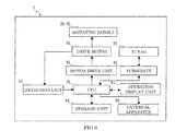
- Fig. 9 is a block diagram illustrating the configuration of the color printer according to the first embodiment of the present invention.
- the color printer 1 includes a central processing unit (CPU) 79, which serves as a control unit.
- the CPU 79 is connected to a storage unit 80, which includes storage devices such as a read-only memory (ROM) and a random access memory (RAM).
- the CPU 79 controls each part of the color printer 1 in accordance with a control program and control data stored in the storage unit 80.
- the control unit may be arranged in the container drive section 26.
- the CPU 79 is also connected to an operation display unit 81 provided in the printer main body 2.
- the operation display unit 81 includes operation keys such as, for example, a start key, a stop/clear key, a power key, a tenkey, and a touch screen. When the user operates one of the operation keys, a corresponding one of operational instructions is output to the CPU 79.
- the operation display unit 81 displays various information including, for example, error messages and the remaining amount of toner in accordance with signals output from the CPU 79.
- the CPU 79 is connected to the above-described rotation detection unit 57.
- a rotation detection signal of the drive motor 55 and the transportation screw 32 (simply referred to as “rotation detection signal” hereafter) detected by the rotation detection unit 57 is output from the rotation detection unit 57 to the CPU 79.
- the CPU 79 is connected to a motor drive unit 82.
- a current flows from the motor drive unit 82 to the drive motor 55 in accordance with a drive instruction signal from the CPU 79, thereby rotating the motor shaft 65 of the drive motor 55.
- the motor drive unit 82 may use, for example, an existing known motor drive circuit that includes a transistor and a resistor.
- the CPU 79 communicates with an external apparatus 84 (for example, a host computer for failure control) provided outside the color printer 1 via, for example, a personal handyphone system (PHS) communication or the like, so that the CPU 79 can notify the external apparatus 84 of an operational state of the color printer 1 and the like where necessary.
- an external apparatus 84 for example, a host computer for failure control
- PHS personal handyphone system
- the CPU 79 is connected to the substrate 61 (RFID substrate) provided in the container drive section 26 as described above.
- the IC tag 53 includes a non-volatile memory.
- This memory stores information about the toner container 25 including, for example, the number of rotations of the transportation screw 32, a type number, a date of manufacture, a serial number, usage history, a color of toner.
- the substrate 61 has a function of reading the information stored in the memory of the IC tag 53 and outputting the read information to the CPU 79 in accordance with a signal from the CPU 79.
- the CPU 79 performs a variety of determinations in accordance with the information about the toner container 25 having been read by the substrate 61.
- the CPU 79 causes the operation display unit 81 to display a determination result where necessary. For example, the CPU 79 determines whether or not the toner container 25 is a genuine part.
- the substrate 61 also has a function of writing various information to the IC tag 53.
- the substrate 61 writes to the IC tag 53 the number of times the rotation detection signal has been output from the rotation detection unit 57 to the CPU 79.
- the substrate 61 has a function of a reader/writer that reads from and writes to the IC tag 53.
- the information about the toner container 25 is erased from the CPU 79.
- the non-volatile memory of the IC tag 53 still holds the information about the toner container 25.
- the information about the toner container 25 held in the memory of the IC tag 53 is read by the substrate 61 and output to the CPU 79, thereby restoring the information about the toner container 25 to the CPU 79.
- the CPU 79 determines whether or not the toner needs to be supplied to the developing unit 11 from the toner container 25. This determination may be performed, for example, in accordance with the amount of toner consumption calculated by the CPU 79 based on the rotation detection signal received from the rotation detection unit 57. Alternatively, the determination may be performed in accordance with the toner consumption amount calculated by the CPU 79 based on a signal regarding the toner concentration or the amount of toner received from a toner sensor (not shown) provided in the developing unit 11. Alternatively, the determination may be performed in accordance with the toner consumption amount calculated by the CPU 79 based on the number of dots of developed images.
- the CPU 79 determines that the toner needs to be supplied to the developing unit 11 as a result of the above-described determination, the CPU 79 outputs a drive instruction signal to the motor drive unit 82 to cause a current to flow from the motor drive unit 82 to the drive motor 55, thereby rotating the motor shaft 65 of the drive motor 55.
- the rotation of the motor shaft 65 is transmitted to the output shaft 56 through the worm 66, the worm gear 67, and the output gear 71, thereby rotating the output shaft 56.
- the rotation of the output shaft 56 is transmitted to the first idle gear 46 through the drive section-side joint 72 and the container-side joint 47.
- the first idle gear 46 rotates in a first direction (clockwise in Fig. 4 ) as the drive motor 55 rotates.
- the transportation gear 37 which is engaged with the first idle gear 46, rotates in a second direction (counterclockwise in Fig. 4 ), thereby rotating the transportation screw 32 also in the second direction.
- the toner contained in the toner container 25 is transported from the discharge port 30 to the developing unit 11 through the pipe 31.
- the toner is supplied to the developing unit 11.
- the first agitating gear 43 which is engaged with the first idle gear 46, rotates in the second direction, thereby rotating the first agitating paddle 38 in the forward rotation direction (see arrow X in Fig. 4 ).
- the second idle gear 48 which is engaged with the first idle gear 46, rotates in the second direction. This causes the second agitating gear 44, which is engaged with the second idle gear 48, to rotate in the first direction, thereby rotating the second agitating paddle 40 in the forward rotation direction (see arrow Y in Fig. 4 ).
- the agitating paddles 38 and 40 rotate in their respective forward rotation directions, the toner contained in the toner container 25 is agitated while being transported in directions toward the transportation screw 32 (in directions indicated by dotted arrows Z).
- the agitating films 49 provided on the agitating paddles 38 and 40 slidingly contact the inner wall surface of the container main body 27 and agitate the toner while scraping off the toner adhering to the inner wall surface of the container main body 27.
- the rotational phases of the agitating paddles 38 and 40 are adjusted such that the agitating films 49 are brought into contact with the inner wall surface of the container main body 27 when the agitating paddles 38 and 40 are stopped (see Fig. 4 ).
- the rotational phases are adjusted, for example, as follows. That is, the CPU 79 calculates the phases of the agitating paddles 38 and 40 in accordance with the number of times the rotation detection signal has been output from the detection unit 57, and outputs a drive stop signal to the motor drive unit 82 at positions where the agitating films 49 contact the inner wall surface of the container main body 27.
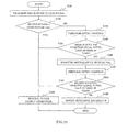
- FIG. 10 is a flowchart illustrating a control process in the color printer 1 according to the first embodiment of the present invention.
- the CPU 79 initially transmits a drive instruction signal (forward rotation direction) to the motor drive unit 82 (S101).
- the motor drive unit 82 Upon receiving the drive instruction signal (forward rotation direction) from the CPU 79, the motor drive unit 82 causes the current to flow in the drive motor 55.
- the motor shaft 65 of the drive motor 55 rotates due to the current, thereby rotating the output shaft 56 and the pulse plate 73.
- the pulse plate 73 rotates, a detection light path from the light emitter 77 to the light receiver 78 is formed and interrupted by the slits 76 and the light shielding portion 75.
- the rotation detection unit 57 transmits the rotation detection signal to the CPU 79.
- the CPU 79 receives the rotation detection signal within a specified time (for example, 200 ms) after the CPU 79 transmitted the drive instruction signal (forward rotation direction) to the motor drive unit 82 (S102), the CPU 79 determines that the toner container 25 is not in the overload state and transmits the drive instruction signal (forward rotation direction) to the motor drive unit 82 to perform a normal toner supply operation (S103).
- the CPU 79 initially transmits the drive stop signal to the motor drive unit 82 to cause the drive motor 55 to stop for a specified time (for example, 500 ms). Next, the CPU 79 transmits the drive instruction signal (reverse rotation direction) to the motor drive unit 82 to cause the drive motor 55 to rotate in the reverse rotation direction for a specified time (for example, 200 ms). After that, the CPU 79 transmits the drive stop signal to the motor drive unit 82 to cause the drive motor 55 to stop for the specified time (for example, 500 ms). Then, the CPU 79 transmits the drive instruction signal (forward rotation direction) to the motor drive unit 82 to cause the drive motor 55 to rotate in the forward rotation direction for the specified time (for example, 200 ms). After that, the CPU 79 transmits the drive stop signal to the motor drive unit 82 to cause the drive motor 55 to stop for the specified time (for example, 500 ms).
- the CPU 79 transmits the drive stop signal to the motor drive unit 82 to cause the drive motor 55 to stop for the
- the CPU 79 repeats the following cycle: transmission of the drive stop signal, transmission of the drive instruction signal (reverse rotation direction), transmission of the drive stop signal, transmission of the drive instruction signal (forward rotation direction), transmission of the drive stop signal, and transmission of the drive instruction signal (reverse rotation direction) in this order.
- the agitating paddles 38 and 40 connected to the drive motor 55 also repeat the following cycle: stop, reverse rotation, stop, forward rotation, stop, and reverse rotation in this order.
- the toner clumped in the toner container 25 is gradually broken up.
- the above-described retry operation of the agitating paddles 38 and 40 is performed within a specified upper limit number of times (for example, 20 times in each of the forward and reverse rotation directions).
- the upper limit number of times is determined for each type of the toner container 25 in accordance with, for example, the capacity of the toner container 25.
- the upper limit number of times is stored in the storage unit 80, the memory of the IC tag 53, or other storage unit.
- the CPU 79 monitors whether or not the rotation detection signal is received from the rotation detection unit 57 within the specified time (for example, 200 ms) every time the CPU 79 transmits the drive instruction signal (forward rotation direction) while causing the agitating paddles 38 and 40 to perform the retry operation.
- the CPU 79 receives the rotation detection signal within the specified time from transmission of the drive instruction signal within the above-described upper limit number of times (S105)
- the CPU 79 determines that the overload state of the toner container 25 has been cleared and ends the retry control.
- the CPU 79 transmits the drive instruction signal (forward rotation direction) to the motor drive unit 82 and performs the normal toner supply operation (S103).
- the CPU 79 determines that the toner container 25 is still in the overload state. In this case, the CPU 79 outputs the determination result to the operation display unit 81 to cause the operation display unit 81 to display a warning notice such as a notice that prompts the user to remove the toner container, shake the toner container well, and remount the toner container. At the same time, the CPU 79 transmits the drive stop signal to the motor drive unit 82 to cause the drive motor 55 to stop (S106).
- the warning notice of the operation display unit 81 is reset and the retry control is again performed (S107).
- the retry operation of the agitating paddles 38 and 40 is performed within a specified upper limit number of times (for example, 15 times in each of the forward and reverse rotation directions).
- the CPU 79 When the CPU 79 receives the rotation detection signal within the specified time from transmission of the drive instruction signal within the above-described upper limit number of times (S108), the CPU 79 determines that the overload state of the toner container 25 has been cleared and ends the retry control.
- the CPU 79 transmits the drive instruction signal (forward rotation direction) to the motor drive unit 82 and performs the normal toner supply operation (S103).
- the CPU 79 determines that the toner container 25 is still in the overload state. In this case, the CPU 79 transmits a signal to the external apparatus 84 via the PHS communication or the like to notify the external apparatus 84 of the overload state of the toner container 25 (S109).
- the retry control is performed so as to break up the clumped toner in the toner container 25, thereby allowing the overload state of the toner container 25 to be cleared.
- work to be performed by the user can be decreased and convenience of the user can be improved.
- rotation of the drive motor 55 is detected by the rotation detection unit 57.
- rotation detection unit 57 detects whether or not the drive motor 55 is rotating.
- the rotational phases of the agitating paddles 38 and 40 are adjusted such that the agitating film 49 of each of the agitating paddles 38 and 40 contacts the inner wall surface of the container main body 27 at the start of use of the toner container 25 and when the agitating paddles 38 and 40 are stopped. Accordingly, when the overload state of the toner container 25 occurs, the above-described retry control can be performed while causing the agitating films 49 to slidingly contact the inner wall surface of the container main body 27.
- vibrations occurring due to forward and reverse rotation of the agitating paddles 38 and 40 can be transmitted through the agitating films 49 to the inner wall surface of the container main body 27, thereby facilitating breaking up the toner adhering to the inner wall surface of the container main body 27.
- the agitating members 42b are provided on one side and the other side of each supporting frame 41 in the axial direction of the supporting frame 41.
- Each agitating member 42b has reverse-taper shapes so that, on a central side of the agitating member 42b in the axial direction of the supporting frame 41, a dimension of the agitating member 42b in the axial direction of the supporting frame 41 increases toward each of the securing plates 39. Accordingly, as the agitating paddles 38 and 40 rotate in the forward and reverse rotation directions in the retry control, forces are generated in directions in which the toner is collected from either side to the central portion in the axial direction of the supporting frame 41. With this structure, circulation of the toner is improved, thereby facilitating breaking up the toner clumped in the toner container 25.
- the rotation detection unit 57 has a structure as follows. That is, the light shielding portion 75 having a flange-like shape is provided in the outer periphery of the pulse plate 73, and the light emitter 77 and the light receiver 78 of the sensor 74 are disposed inside and outside the light shielding portion 75 in the radial direction of the pulse plate 73.
- an outer diameter area of the pulse plate 73 may serve as the light shielding portion 75, and the light emitter 77 and the light receiver 78 of the sensor 74 may be disposed on one side and the other side of the pulse plate 73 in the width direction of the pulse plate 73.
- the shape of the pulse plate 73 and arrangement of the sensor 74 may be modified where appropriate in accordance with the layout of a product and the like.
- the pulse plate 73 has 12 slits 76.
- eight slits 76 may be formed in the pulse plate 73.
- the number of slits 76 may be changed where appropriate in accordance with the speed reduction ratio of gears that connect the transportation screw 32 to the pulse plate 73, required detection accuracy, or the like.
- the pulse plate 73 is coaxial with the output shaft 56. In yet another embodiment, the pulse plate 73 may be coaxial with the transportation screw 32 or a different shaft. That is, the pulse plate 73 may be disposed at any position in a rotation transmission mechanism from the drive motor 55 to the transportation screw 32.
- the rotation detection unit 57 including the pulse plate 73 and the sensor 74 is used. In yet another embodiment, the rotation detection unit 57 may include the rotation detection unit 57 having another structure such as a magnetic rotary encoder, a mechanical rotary encoder, or the like.
- Fig. 12 is a block diagram illustrating the configuration of the color printer according to the second embodiment of the present invention.
- the rotation detection unit 57 including the pulse plate 73 and the sensor 74 serves as the detection unit.
- an overcurrent detection circuit 83 serves as the detection unit.
- the overcurrent detection circuit 83 is connected to the drive motor 55 and the CPU 79.
- the overcurrent detection circuit 83 transmits an overcurrent detection signal to the CPU 79 when the current flowing in the drive motor 55 (referred to as a "drive current” hereafter) exceeds (or is equal to) a threshold value (for example, 0.3 A or 0.9 A).
- the overcurrent detection circuit 83 may be structured by an existing known circuit that includes, for example, a resistor used to detect the drive current and a comparator that compares the current detected by the resistor to the threshold value.
- the above-described threshold value of the drive current is determined in accordance with the capacity of the toner container 25 or the like and stored in the storage unit 80, the memory of the IC tag 53, or other storage unit.
- Fig. 13 is a flowchart illustrating a control process in the color printer 1 according to the second embodiment of the present invention.
- the CPU 79 initially transmits a drive instruction signal (forward rotation direction) to the motor drive unit 82 (S201).
- the motor drive unit 82 Upon receiving the drive instruction signal (forward rotation direction) from the CPU 79, the motor drive unit 82 causes the current to flow in the drive motor 55.
- the overcurrent detection circuit 83 does not transmit the overcurrent detection signal to the CPU 79.
- the CPU 79 does not receive the overcurrent detection signal (S202).
- the CPU 79 determines that the drive motor 55 is not in the overload state and transmits the drive instruction signal (forward rotation direction) to the motor drive unit 82 and performs the normal toner supply operation (S203).
- the overcurrent detection circuit 83 transmits the overcurrent detection signal to the CPU 79.
- the CPU 79 receives the overcurrent detection signal (S202), determines that the toner container 25 is in the overload state, and performs the retry control similar to that performed in the above-described first embodiment (S204).
- the CPU 79 repeats the following cycle: transmission of the drive stop signal, transmission of the drive instruction signal (reverse rotation direction), transmission of the drive stop signal, transmission of the drive instruction signal (forward rotation direction), transmission of the drive stop signal, and transmission of the drive instruction signal (reverse rotation direction) in this order.
- the agitating paddles 38 and 40 connected to the drive motor 55 also repeats the following cycle: stop, reverse rotation, stop, forward rotation, stop, and reverse rotation in this order. With this operation, the toner clumped in the toner container 25 is gradually broken up.
- the CPU 79 monitors whether or not the overcurrent detection signal is transmitted from the overcurrent detection circuit 83 every time the CPU 79 transmits the drive instruction signal (forward rotation direction) while causing the agitating paddles 38 and 40 to perform the retry operation.
- the CPU 79 does not receive the overcurrent detection signal from the overcurrent detection circuit 83 within the upper limit number of times the retry control is performed (for example, 20 times in each of the forward and reverse rotation direction) (S205)
- the CPU 79 determines that the overload state of the toner container 25 has been cleared and ends the retry control.
- the CPU 79 transmits the drive instruction signal (forward rotation direction) to the motor drive unit 82 and performs the normal toner supply operation (S203).
- the CPU 79 determines that the toner container 25 is still in the overload state. In this case, the CPU 79 outputs the determination result to the operation display unit 81 to cause the operation display unit 81 to display a warning notice such as a notice that prompts the user to remove the toner container, shake the toner container well, and remount the toner container. At the same time, the CPU 79 transmits the drive stop signal to the motor drive unit 82 to cause the drive motor 55 to stop (S206).
- the warning notice of the operation display unit 81 is reset and the retry control is again performed (S207).
- the retry operation of the agitating paddles 38 and 40 is performed within a specified upper limit number of times (for example, 15 times in each of the forward and reverse rotation directions).
- the CPU 79 determines that the overload state of the toner container 25 has been cleared and ends the retry control.
- the CPU 79 transmits the drive instruction signal (forward rotation direction) to the motor drive unit 82 and performs the normal toner supply operation (S203).
- the CPU 79 determines that the toner container 25 is still in the overload state. In this case, the CPU 79 transmits a signal to the external apparatus 84 to notify the external apparatus 84 of the overload state of the toner container 25 (S209).
- the current flowing in the drive motor 55 is detected. According to this structure, whether or not the drive motor 55 is rotating can be detected without use of components such as the pulse plate 73 and the sensor 74. Thus, the structure of the device can be simplified.
- the overcurrent flowing in the drive motor 55 is detected by the overcurrent detection circuit 83.
- the overcurrent flowing in the output stage of the motor drive circuit as the motor drive unit 82 may be detected by the overcurrent detection circuit 83.
- the overcurrent detection circuit 83 compares the value of the drive current flowing in the drive motor 55 to the threshold value.
- the CPU 79 may compare the value of the drive current flowing in the drive motor 55 to the threshold value.
- the retry control when the overload state of the toner container 25 is cleared, the retry control is ended regardless of whether or not the retry control has been performed the specified upper limit number of times, and the normal toner supply operation is performed. In this case, an advantage of decreasing a standby time for the user can be obtained. In contrast, in yet another embodiment, the retry control may be performed until the specified upper limit number of times is reached. In this case, there is an advantage in that the overload state of the toner container 25 can be more reliably cleared.
- the transportation unit is structured by the transportation screw 32.
- the transportation unit may be structured by a roller-shaped member.
- the shutter that opens and closes the discharge port 30 may be provided with the transportation unit.
- the shutter is connected to the drive motor 55.
- the agitating units are structured by the agitating paddles 38 and 40.
- the agitating unit may be structured by a screw-shaped member in yet another embodiment.
- the toner container 25 is connected to the developing unit 11 through the toner pipe 31.
- the toner container 25 may be connected to the developing unit 11 through an intermediate hopper, or the toner container 25 may be directly removably attached to the developing unit 11.
- the present disclosure is applied to the tandem color printer 1.
- the present disclosure may be applicable to rotary color printers, monochrome printers, copying machines, digital multi-function peripherals, facsimile machines, and other image forming apparatuses.
Landscapes
- Physics & Mathematics (AREA)
- General Physics & Mathematics (AREA)
- Dry Development In Electrophotography (AREA)
- Control Or Security For Electrophotography (AREA)
Abstract
Description
- This application is based upon and claims the benefit of priority from the corresponding Japanese Patent application No.
2011-062009, filed March 22, 2011 - The present invention relates to a toner transportation device that supplies toner to a developing unit, a toner containing case that contains toner, an image forming apparatus equipped with the toner transportation device and the toner containing case, and a control method of a toner transportation device.
- Today, in electrophotographic image forming apparatuses, toner is supplied from a developing unit to an electrostatic latent image formed on the surface of a photoconductor drum or the like to perform a developing process. Toner used in such a developing process is supplied to the developing unit from a toner containing case using a transportation unit while being agitated by an agitating unit.
- In an image forming apparatus having such a structure, the toner containing case may be in an overload state immediately after the toner containing case is replaced or when an image forming operation has not been performed for a long time. Herein, the overload state of the toner containing case refers to a state in which toner has become clumped in the toner containing case because of the weight of the toner or other causes. When the toner is supplied from the toner containing case to the developing unit in such a state, an excessive load torque is applied to the agitating unit and a driving unit that drives a transportation unit. As a result, there is a possibility of the driving unit being damaged.
- In order to prevent such a situation from occurring, there are known image forming apparatuses that stop the driving unit, when it is detected that the toner containing case is in the overload state, and display a warning notice such as a notice that prompts a user, for example, to remove the toner container, shake the toner container well, and remount the toner container, or display an error notice such as a notice that prompts the user to contact a service engineer.
- However, when a warning notice as described above is displayed, an operation of clearing the overload state of the toner container will be performed by the user. This increases the amount of work performed by the user. When an error notice as described above is displayed, the user cannot use the image forming apparatus until the toner container is replaced by a service engineer. This decreases convenience. Accordingly, there is a need in the art to obviate the above drawbacks of the prior art.
- According to an aspect of the present invention, a toner transportation device includes a toner containing case and a drive section. The toner containing case includes a case main body that contains toner, and an agitating unit rotatably provided in the case main body and agitates the toner. The drive section includes a driving unit that drives the agitating unit, a detection unit that detects a driving state of the driving unit, and a control unit that is able to transmit a drive instruction signal to the driving unit and is able to receive a detection signal regarding the driving state of the driving unit from the detection unit. In the toner transportation device, the control unit determines whether or not the toner containing case is in an overload state in accordance with a reception state of the detection signal from the detection unit. The control unit performs retry control when the control unit determines that the toner containing case is in the overload state. The retry control is control that causes the driving unit to repeatedly rotate the agitating unit in forward and reverse rotation directions.
- According to another aspect of the present invention, a toner containing case includes a case main body that contains toner, and an agitating unit rotatably provided in the case main body and agitates the toner. The toner containing case is connected to a toner transportation device that includes a drive section. The drive section includes a driving unit that drives the agitating unit, a detection unit that detects a driving state of the driving unit, and control unit that is able to transmit a drive instruction signal to the driving unit and is able to receive a detection signal regarding the driving state of the driving unit from the detection unit. The control unit determines whether or not the toner containing case is in an overload state in accordance with a reception state of the detection signal from the detection unit. The control unit performs retry control when the control unit determines that the toner containing case is in the overload state. The retry control is control that causes the driving unit to repeatedly rotate the agitating unit in forward and reverse rotation directions.
- According to yet another aspect of the present invention, an image forming apparatus includes a toner containing case, a drive section, and a control unit. The toner containing case includes a case main body that contains toner, and an agitating unit rotatably provided in the case main body and agitates the toner. The drive section includes a driving unit that drives the agitating unit, and a detection unit that detects a driving state of the driving unit. The control unit is able to transmit a drive instruction signal to the driving unit and is able to receive a detection signal regarding the driving state of the driving unit from the detection unit. The control unit determines whether or not the toner containing case is in an overload state in accordance with a reception state of the detection signal from the detection unit. The control unit performs retry control when the control unit determines that the toner containing case is in the overload state. The retry control is control that causes the driving unit to repeatedly rotate the agitating unit in forward and reverse rotation directions.
- According to yet another aspect of the present invention, a control method of a toner transportation device is used for a toner transportation device that includes a toner containing case including an agitating unit that agitates toner, and a drive section including a driving unit that drives the agitating unit. The control method of a toner transportation device includes transmitting a drive instruction signal to the driving unit, detecting a driving state of the driving unit and determining whether or not the toner containing case is in an overload state, and performing retry control when it is determined that the toner containing case is in the overload state. The retry control is control that causes the driving unit to repeatedly rotate the agitating unit in forward and reverse rotation directions.
-
-
Fig. 1 is a schematic diagram illustrating an outline of the structure of a color printer according to a first embodiment of the present invention; -
Fig. 2 is a perspective view illustrating connection of a toner transportation device to a developing unit in the color printer according to the first embodiment of the present invention; -
Fig. 3 is a plan view of a toner container with a cover of the toner container removed in the color printer according to the first embodiment of the present invention; -
Fig. 4 is a rear view of a gear mechanism provided in the toner container in the color printer according to the first embodiment of the present invention; -
Fig. 5 is a perspective view illustrating an agitating paddle used as first and second agitating paddles in the color printer according to the first embodiment of the present invention; -
Fig. 6 is a perspective view of a container drive section in the color printer according to the first embodiment of the present invention seen from the front side; -
Fig. 7 is a perspective view of the container drive section in the color printer according to the first embodiment of the present invention seen from the rear side; -
Fig. 8 is a bottom view of the gear mechanism provided in the container drive section in the color printer according to the first embodiment of the present invention; -
Fig. 9 is a block diagram illustrating the configuration of the color printer according to the first embodiment of the present invention; -
Fig. 10 is a flowchart illustrating a control process in the color printer according to the first embodiment of the present invention; -
Fig. 11 is a perspective view of a rotation detection unit according to another embodiment of the present invention; -
Fig. 12 is a block diagram illustrating the configuration of the color printer according to a second embodiment of the present invention; and -
Fig. 13 is a flowchart illustrating a control process in the color printer according to the second embodiment of the present invention. - The general structure of a color printer 1 is initially described with reference to
Fig. 1 . The color printer 1 serves as an image forming apparatus.Fig. 1 is a schematic diagram illustrating an outline of the structure of the color printer according to a first embodiment of the present invention. - The color printer 1 includes a box-shaped printer
main body 2. Asheet feed cassette 3 is provided in a lower portion of the printermain body 2. Sheets of transfer paper (not shown) are loaded in thesheet feed cassette 3. A delivery tray 4 is provided at an upper end of the printermain body 2. - An
intermediate transfer belt 5 is provided in an upper portion of the printermain body 2. Theintermediate transfer belt 5, which serves as an image carrying body, is stretched around a plurality of rollers. Anexposure unit 10, which includes a laser scanning unit (LSU), is disposed below theintermediate transfer belt 5. A plurality of image forming units 6 are provided along a lower portion of theintermediate transfer belt 5. The image forming units 6 are provided for corresponding colors that include, for example, yellow (Y), magenta (M), cyan (C), and black (K). Aphotoconductor drum 7 is rotatably provided in each of the image forming units 6. Acharger 8, a developingunit 11, aprimary transfer unit 12, acleaning device 13, and aneraser 14 are disposed around thephotoconductor drum 7 in the order of processes of primary transfer. - A pair of agitating
rollers 15 is provided in a lower portion of each of the developingunit 11. Amagnetic roller 16 is provided above each pair of the agitatingrollers 15, and a developingroller 17 is provided above eachmagnetic roller 16.Toner transportation devices 18 are provided above the developingunits 11. The details of thetoner transportation devices 18 will be described later. - A
transportation path 20, through which a transfer sheet is transported, is formed on one side (right side inFig. 1 ) of the printermain body 2. Along thetransportation path 20, asheet feed unit 21 is provided at an upstream end, asecondary transfer unit 22 is provided at one end (right end inFig. 1 ) of theintermediate transfer belt 5 in a midstream, a fixingunit 23 is provided in a downstream, and asheet delivery port 24 is provided at a downstream end. - Next, an image forming operation of the color printer 1 having the above-described structure will be described.
- When power of the color printer 1 is turned on, a variety of parameters are initialized, and initial settings such as a temperature setting of the fixing
unit 23 are performed. When image data is input to the color printer 1 from a computer or the like connected to the color printer 1 and the color printer 1 is instructed to start printing, the image forming operation is performed as follows. - That is, a surface of one of the photoconductor drums 7 is initially charged by the corresponding
charger 8. After that, thephotoconductor drum 7 is exposed to laser light (see arrow P inFig. 1 ) emitted from theexposure unit 10 corresponding to the image data, thereby forming an electrostatic latent image on the surface of thephotoconductor drum 7. Next, the developingunit 11 develops the electrostatic latent image to a toner image of a corresponding one of the colors. This toner image undergoes primary transfer onto a surface of theintermediate transfer belt 5 using theprimary transfer unit 12. The image forming units 6 sequentially performs the above-described operation to form a full-color toner image on theintermediate transfer belt 5. Toner and electrical charges remaining on the photoconductor drums 7 are removed by thecleaning device 13 and theeraser 14. - A transfer sheet picked up by the
sheet feed unit 21 from thesheet feed cassette 3 or a manual feed tray (not shown) is transported to thesecondary transfer unit 22 at a timing adjusted with respect to a timing of the image forming operation. The full-color toner image on theintermediate transfer belt 5 undergoes secondary transfer onto the transfer sheet in thesecondary transfer unit 22. The transfer sheet onto which the secondary transfer of the toner image has been performed is transported toward the downstream through thetransportation path 20 and enters the fixingunit 23. The fixingunit 23 fixes the toner image onto the transfer sheet. The transfer sheet onto which the toner image has been fixed is delivered to the delivery tray 4 from thesheet delivery port 24. - Next, the structure of the
toner transportation device 18 will be described with reference toFigs. 2 to 8 . For convenience of explanation, a left front side inFig. 2 is hereafter referred to as a front surface side of thetoner transportation device 18.Fig. 2 is a perspective view illustrating connection of the toner transportation device to the developing unit in the color printer according to the first embodiment of the present invention.Fig. 3 is a plan view of a toner container with a cover of the toner container removed in the color printer according to the first embodiment of the present invention.Fig. 4 is a rear view of a gear mechanism provided in the toner container in the color printer according to the first embodiment of the present invention.Fig. 5 is a perspective view illustrating an agitating paddle used as first and second agitating paddles in the color printer according to the first embodiment of the present invention.Fig. 6 is a perspective view of a container drive section in the color printer according to the first embodiment of the present invention seen from the front side.Fig. 7 is a perspective view of the container drive section in the color printer according to the first embodiment of the present invention seen from the rear side.Fig. 8 is a bottom view of the gear mechanism provided in the container drive section in the color printer according to the first embodiment of the present invention. - As illustrated in
Fig. 2 , eachtoner transportation device 18 includes atoner container 25 and acontainer drive section 26. Thetoner container 25, which serves as a toner containing case, is provided above the corresponding one of the developingunits 11. Thecontainer drive section 26 is connected to one longitudinal end (rear end in the present embodiment) of thetoner container 25. - The
toner container 25 contains toner. Thetoner container 25 is removably mounted in a toner container mounting unit (not shown) provided in the printermain body 2. Thetoner container 25 is replaceable when thetoner container 25 has run out of toner. - The
toner container 25 includes a containermain body 27 and acover 28. The containermain body 27, which serves as a case main body, has a box shape with an upper side open, and thecover 28 covers the upper side of the containermain body 27. - As illustrated in
Fig. 3 , the containermain body 27 has abottom wall 29. Adischarge port 30 is formed in a front portion of thebottom wall 29. Thedischarge port 30 is connected to an inner portion of the developingunit 11 through a pipe 31 (seeFig. 2 ) arranged therebetween in a position substantially vertical to the printermain body 2. When thetoner container 25 is not mounted in the printermain body 2, thedischarge port 30 is closed by a rotating shutter (not shown), which is connected to a lever (not shown). Mounting thetoner container 25 in the printermain body 2 unlocks the lever. Then, an operation of the lever performed by a user causes the shutter to rotate, thereby opening thedischarge port 30. Although the rotating shutter is used as described above in the present embodiment, a sliding shutter may be used in another embodiment. In this case, mounting thetoner container 25 in the printermain body 2 causes thedischarge port 30 to be opened. - In the container
main body 27, atransportation screw 32, which serves as a transportation unit, is rotatably mounted above thedischarge port 30. Thetransportation screw 32 includes arotation shaft 35, aspiral fin 36, and a transportation gear 37 (seeFig. 4 ). Longitudinal end portions of therotation shaft 35 are rotatably supported by front andrear side walls main body 27. Thespiral fin 36 is provided in an outer periphery of therotation shaft 35 so as to be concentric with therotation shaft 35. Thetransportation gear 37 is provided at one of the longitudinal ends (rear end in the present embodiment) of therotation shaft 35. - A first agitating
paddle 38 and a second agitatingpaddle 40 are provided in the containermain body 27. The first agitatingpaddle 38, which serves as a first agitating unit, is rotatably provided on one side above the transportation screw 32 (upper left side in the present embodiment). The second agitatingpaddle 40, which serves as a second agitating unit, is rotatably provided on another side above the transportation screw 32 (upper right side in the present embodiment). In the present embodiment, a counterclockwise direction seen from the rear side is referred to as a forward rotation direction of the first agitating paddle 38 (see arrow X inFig. 4 ), and a clockwise direction seen from the rear side is referred to as a forward rotation direction of the second agitating paddle 40 (see arrow Y inFig. 4 ). - Each of the agitating paddles 38 and 40 is rotatably supported in a direction parallel to the
rotation shaft 35 of thetransportation screw 32 and has a shape extending in the axial direction. As most clearly illustrated inFig. 5 , each of the agitating paddles 38 and 40 has a rectangular frame plate-shaped supportingframe 41 provided in the axial direction. Front and rear end portions of each of the supportingframes 41 are rotatably supported by the front andrear side walls main body 27. The supportingframe 41 has a pair of securing plates 39 (securing members) provided in the axial direction. The pair of securingplates 39 oppose each other. - On each of the pair of securing
plates 39, a plurality of agitatingmembers frame 41. The plurality of agitatingmembers members frame 41. Each end of each of the agitatingmembers members frame 41 in a staggered manner such that the longitudinal position of any one of agitatingmembers members Fig. 3 ). The agitatingmembers 42a are provided in a central portion in the axial direction of each supportingframe 41. The width of each agitatingmember 42a is substantially uniform. The agitatingmembers 42b are provided on one side and the other side of each supportingframe 41 in the axial direction of the supportingframe 41. Each agitatingmember 42b has reverse-taper shapes so that, on a central side of the agitatingmember 42b in the axial direction of the supportingframe 41, a dimension of the agitatingmember 42b in the axial direction of the supportingframe 41 increases from a central portion toward each end portion of the agitatingmember 42b. - An agitating
film 49 is secured to an outer surface of one of the securingplates 39 in a range from the front to rear end portions. The agitatingfilms 49 rotate together with the corresponding agitatingpaddles main body 27. That is, each of the agitatingfilms 49 slidingly contacts the inner wall surface of the containermain body 27 when the agitatingfilm 49 is positioned on a lower side of the supportingframe 41 due to rotation of the corresponding agitatingpaddle films 49 moves away from the inner wall surface of the containermain body 27 when the agitatingfilm 49 is positioned on an upper side of the supportingframe 41 due to rotation of the corresponding agitatingpaddle - Rotational phases of the agitating paddles 38 and 40 are adjusted such that, at the start of use of the toner container 25 (immediately after replacement of the toner container 25), the agitating
film 49 of each of the agitating paddles 38 and 40 contacts the inner wall surface of the container main body 27 (seeFig. 4 ). That is, rotational positions in which the agitating paddles 38 and 40 are mounted are adjusted such that the agitatingfilms 49 are positioned on the lower side of the corresponding supportingframes 41 at the start of use of thetoner container 25. With the above-described structure, the toner is easily broken up due to vibrations transmitted from the agitatingfilms 49 to the containermain body 27 when retry control is performed. The retry control will be described later. The rotational phases may be adjusted such that the agitatingfilms 49 are brought into contact with the inner wall surface of the containermain body 27 every time the agitating paddles 38 and 40 are stopped. A first agitatinggear 43 is provided in the rear end portion of the supportingframe 41 of the first agitatingpaddle 38. A second agitatinggear 44 is provided in the rear end portion of the supportingframe 41 of the second agitatingpaddle 40. - As illustrated in
Fig. 4 , arear surface cover 45 is mounted on therear side wall 34 of the containermain body 27. InFig. 4 , only part of therear surface cover 45 is illustrated. Near a lower central portion of therear side wall 34, a firstidle gear 46 is provided. The firstidle gear 46 is engaged with thetransportation gear 37 and the first agitatinggear 43. In the present embodiment, the gear ratio of the firstidle gear 46 to thetransportation gear 37 is set to 3:2. The firstidle gear 46 has a container-side joint 47. A secondidle gear 48 is engaged with the firstidle gear 46 and the second agitatinggear 44. The secondidle gear 48 is formed to have a size and shape similar to those of the firstidle gear 46. Therear side wall 34 of the containermain body 27 has a pair of cylindrically shaped engagingcylinders 50 provided in the upper central portion and the lower left end portion. - The
cover 28 is secured to the containermain body 27 using ultrasonic welding. Thecover 28 has a rectangular-shapedprotrusion 52 arranged on arear wall 51 thereof. An integrated circuit (IC) tag 53 (a radio frequency identification (RFID) tag) is attached to theprotrusion 52. The details of theIC tag 53 will be described later. - The
container drive section 26 is disposed in a rear portion of the printermain body 2. Thecontainer drive section 26 is removably mounted to thetoner container 25. As illustrated inFigs. 6 and7 , thecontainer drive section 26 includes aframe member 54, adrive motor 55, anoutput shaft 56, and adetection unit 57. Theframe member 54 is an outer frame of thecontainer drive section 26. Thedrive motor 55, which serves as a driving unit, is secured to theframe member 54 on one side (left side in the present embodiment) of theframe member 54 in a substantially vertical position. Theoutput shaft 56 disposed in the longitudinal direction is rotatably supported on the other side (right side in the present embodiment) of theframe member 54. Thedetection unit 57 is provided at a rear end of theoutput shaft 56. - A
substrate mounting unit 60 is provided at a position on afront surface 58 of theframe member 54 corresponding to the position of theprotrusion 52 of thetoner container 25. A substrate 61 (an RFID substrate) is mounted on thissubstrate mounting unit 60. When thetoner container 25 is mounted in the printermain body 2, thesubstrate 61 opposes theIC tag 53. The details of thesubstrate 61 will be described later. Engagingprotrusions 63 are provided at positions on thefront surface 58 of theframe member 54 corresponding to the positions of the corresponding engagingcylinders 50 of thetoner container 25. When thetoner container 25 is mounted in the printermain body 2, the engagingcylinders 50 are engaged with the corresponding engagingprotrusions 63. Aninsertion hole 64 is formed in a horizontal direction in a lower central portion of theframe member 54. - The
drive motor 55 is a direct-current (DC) brush motor. In another embodiment, as thedrive motor 55, any motor such as a DC brushless motor or a stepping motor instead of a DC brush motor may be used. Thedrive motor 55 has amotor shaft 65 extending downward, to which aworm 66 is secured. As most clearly illustrated inFig. 8 , theworm 66 is engaged with alarge diameter portion 68 of aworm gear 67 rotatably supported by theframe member 54. Asmall diameter portion 70 of theworm gear 67 is engaged with anoutput gear 71, which rotates together with theoutput shaft 56. When thedrive motor 55 rotates, the rotation of thedrive motor 55 is transmitted to theoutput shaft 56 through theworm 66, theworm gear 67, and theoutput gear 71, thereby rotating theoutput shaft 56. - The
output shaft 56 is urged forward by acoil spring 69. A front portion of theoutput shaft 56 is inserted through theinsertion hole 64. A drive section-side joint 72 is provided at a front end of theoutput shaft 56. The drive section-side joint 72 is provided at a position corresponding to the position of the container-side joint 47, which is provided in the firstidle gear 46 of thetoner container 25. Mounting of thetoner container 25 in the printermain body 2 causes the container-side joint 47 to be engaged with the drive section-side joint 72, thereby allowing rotation of theoutput shaft 56 to be transmitted to the firstidle gear 46 of thetoner container 25. - As illustrated in
Fig. 7 , therotation detection unit 57 includes apulse plate 73 and asensor 74. Thepulse plate 73 is provided on the rear end of theoutput shaft 56 so as to be rotatable together with theoutput shaft 56. Thesensor 74 is secured to theframe member 54 at a position above thepulse plate 73. Thepulse plate 73 is integrated with the output gear 71 (seeFig. 8 ). Alight shielding portion 75 is provided in an outer periphery of thepulse plate 73. Thelight shielding portion 75 has a rearwardly protruding flange-like shape. Thelight shielding portion 75 has 12slits 76 equally spaced in a peripheral direction thereof. - The
sensor 74 is a photo interrupter sensor (a PI sensor) and includes alight emitter 77 and alight receiver 78. Thelight emitter 77 is disposed inside thelight shielding portion 75 in a radial direction of thepulse plate 73. Thelight receiver 78 is disposed outside thelight shielding portion 75 in the radial direction of thepulse plate 73. Thelight emitter 77 and thelight receiver 78 oppose each other and are disposed on one side and the other side of thelight shielding portion 75. When thepulse plate 73 rotates, a detection light path from thelight emitter 77 to thelight receiver 78 is formed and interrupted by theslits 76 and thelight shielding portion 75. By detecting formation and interruption, rotation of thepulse plate 73 can be detected. Thepulse plate 73 rotates as thedrive motor 55 and thetransportation screw 32 rotate in an interlocked manner. Accordingly, rotation of thedrive motor 55 and thetransportation screw 32 can be detected by detecting rotation of thepulse plate 73. - In the present embodiment, since the
pulse plate 73 has 12slits 76, thesensor 74 detects 12 pulses during one rotation of thepulse plate 73. As described above, the gear ratio of the firstidle gear 46, which is connected to theoutput shaft 56, to thetransportation gear 37, which is provided to thetransportation screw 32, is set to 3:2. Accordingly, while thetransportation screw 32 performs one rotation, theoutput shaft 56 performs two thirds of a rotation, as a result of which thesensor 74 detects eight pulses. - Next, a control system of the color printer 1 will be described with reference to
Fig. 9. Fig. 9 is a block diagram illustrating the configuration of the color printer according to the first embodiment of the present invention. - The color printer 1 includes a central processing unit (CPU) 79, which serves as a control unit. The
CPU 79 is connected to astorage unit 80, which includes storage devices such as a read-only memory (ROM) and a random access memory (RAM). TheCPU 79 controls each part of the color printer 1 in accordance with a control program and control data stored in thestorage unit 80. The control unit may be arranged in thecontainer drive section 26. - The
CPU 79 is also connected to anoperation display unit 81 provided in the printermain body 2. Theoperation display unit 81 includes operation keys such as, for example, a start key, a stop/clear key, a power key, a tenkey, and a touch screen. When the user operates one of the operation keys, a corresponding one of operational instructions is output to theCPU 79. Theoperation display unit 81 displays various information including, for example, error messages and the remaining amount of toner in accordance with signals output from theCPU 79. - The
CPU 79 is connected to the above-describedrotation detection unit 57. A rotation detection signal of thedrive motor 55 and the transportation screw 32 (simply referred to as "rotation detection signal" hereafter) detected by therotation detection unit 57 is output from therotation detection unit 57 to theCPU 79. - The
CPU 79 is connected to amotor drive unit 82. A current flows from themotor drive unit 82 to thedrive motor 55 in accordance with a drive instruction signal from theCPU 79, thereby rotating themotor shaft 65 of thedrive motor 55. Themotor drive unit 82 may use, for example, an existing known motor drive circuit that includes a transistor and a resistor. - The
CPU 79 communicates with an external apparatus 84 (for example, a host computer for failure control) provided outside the color printer 1 via, for example, a personal handyphone system (PHS) communication or the like, so that theCPU 79 can notify theexternal apparatus 84 of an operational state of the color printer 1 and the like where necessary. - The
CPU 79 is connected to the substrate 61 (RFID substrate) provided in thecontainer drive section 26 as described above. Thesubstrate 61 and the IC tag 53 (RFID tag), which opposes thesubstrate 61 and is bonded to thetoner container 25 as described above, perform wireless communication with each other as follows. - That is, the
IC tag 53 includes a non-volatile memory. This memory stores information about thetoner container 25 including, for example, the number of rotations of thetransportation screw 32, a type number, a date of manufacture, a serial number, usage history, a color of toner. Thesubstrate 61 has a function of reading the information stored in the memory of theIC tag 53 and outputting the read information to theCPU 79 in accordance with a signal from theCPU 79. TheCPU 79 performs a variety of determinations in accordance with the information about thetoner container 25 having been read by thesubstrate 61. TheCPU 79 causes theoperation display unit 81 to display a determination result where necessary. For example, theCPU 79 determines whether or not thetoner container 25 is a genuine part. Thesubstrate 61 also has a function of writing various information to theIC tag 53. For example, thesubstrate 61 writes to theIC tag 53 the number of times the rotation detection signal has been output from therotation detection unit 57 to theCPU 79. Thus, thesubstrate 61 has a function of a reader/writer that reads from and writes to theIC tag 53. - When a
particular toner container 25 is removed from the printermain body 2, the information about thetoner container 25 is erased from theCPU 79. However, the non-volatile memory of theIC tag 53 still holds the information about thetoner container 25. When theparticular toner container 25 is again mounted in the printermain body 2, the information about thetoner container 25 held in the memory of theIC tag 53 is read by thesubstrate 61 and output to theCPU 79, thereby restoring the information about thetoner container 25 to theCPU 79. - Next, an operation in which toner is supplied from one of the
toner transportation devices 18 to a corresponding one of the developingunits 11 in the above-described color printer 1 will be described. - When the image forming operation, as described above, is performed, and accordingly, toner in the developing
unit 11 is consumed, theCPU 79 determines whether or not the toner needs to be supplied to the developingunit 11 from thetoner container 25. This determination may be performed, for example, in accordance with the amount of toner consumption calculated by theCPU 79 based on the rotation detection signal received from therotation detection unit 57. Alternatively, the determination may be performed in accordance with the toner consumption amount calculated by theCPU 79 based on a signal regarding the toner concentration or the amount of toner received from a toner sensor (not shown) provided in the developingunit 11. Alternatively, the determination may be performed in accordance with the toner consumption amount calculated by theCPU 79 based on the number of dots of developed images. - When the
CPU 79 determines that the toner needs to be supplied to the developingunit 11 as a result of the above-described determination, theCPU 79 outputs a drive instruction signal to themotor drive unit 82 to cause a current to flow from themotor drive unit 82 to thedrive motor 55, thereby rotating themotor shaft 65 of thedrive motor 55. The rotation of themotor shaft 65 is transmitted to theoutput shaft 56 through theworm 66, theworm gear 67, and theoutput gear 71, thereby rotating theoutput shaft 56. The rotation of theoutput shaft 56 is transmitted to the firstidle gear 46 through the drive section-side joint 72 and the container-side joint 47. - By this matter, as illustrated in
Fig. 4 , the firstidle gear 46 rotates in a first direction (clockwise inFig. 4 ) as thedrive motor 55 rotates. As the firstidle gear 46 rotates, thetransportation gear 37, which is engaged with the firstidle gear 46, rotates in a second direction (counterclockwise inFig. 4 ), thereby rotating thetransportation screw 32 also in the second direction. As a result, the toner contained in thetoner container 25 is transported from thedischarge port 30 to the developingunit 11 through thepipe 31. Thus, the toner is supplied to the developingunit 11. - As the above-described first
idle gear 46 rotates, the first agitatinggear 43, which is engaged with the firstidle gear 46, rotates in the second direction, thereby rotating the first agitatingpaddle 38 in the forward rotation direction (see arrow X inFig. 4 ). At the same time, the secondidle gear 48, which is engaged with the firstidle gear 46, rotates in the second direction. This causes the second agitatinggear 44, which is engaged with the secondidle gear 48, to rotate in the first direction, thereby rotating the second agitatingpaddle 40 in the forward rotation direction (see arrow Y inFig. 4 ). As the agitating paddles 38 and 40 rotate in their respective forward rotation directions, the toner contained in thetoner container 25 is agitated while being transported in directions toward the transportation screw 32 (in directions indicated by dotted arrows Z). As the agitating paddles 38 and 40 rotate, the agitatingfilms 49 provided on the agitating paddles 38 and 40 slidingly contact the inner wall surface of the containermain body 27 and agitate the toner while scraping off the toner adhering to the inner wall surface of the containermain body 27. - The rotational phases of the agitating paddles 38 and 40 are adjusted such that the agitating
films 49 are brought into contact with the inner wall surface of the containermain body 27 when the agitating paddles 38 and 40 are stopped (seeFig. 4 ). The rotational phases are adjusted, for example, as follows. That is, theCPU 79 calculates the phases of the agitating paddles 38 and 40 in accordance with the number of times the rotation detection signal has been output from thedetection unit 57, and outputs a drive stop signal to themotor drive unit 82 at positions where the agitatingfilms 49 contact the inner wall surface of the containermain body 27. - Next, how the
CPU 79 performs the retry control when an overload state of thetoner container 25 occurs immediately after replacement of thetoner container 25 or when an image forming operation has not been performed for a long time will be described.Fig. 10 is a flowchart illustrating a control process in the color printer 1 according to the first embodiment of the present invention. - The
CPU 79 initially transmits a drive instruction signal (forward rotation direction) to the motor drive unit 82 (S101). Upon receiving the drive instruction signal (forward rotation direction) from theCPU 79, themotor drive unit 82 causes the current to flow in thedrive motor 55. When thetoner container 25 is not in the overload state, themotor shaft 65 of thedrive motor 55 rotates due to the current, thereby rotating theoutput shaft 56 and thepulse plate 73. As thepulse plate 73 rotates, a detection light path from thelight emitter 77 to thelight receiver 78 is formed and interrupted by theslits 76 and thelight shielding portion 75. When thesensor 74 of therotation detection unit 57 detects the formation and interruption of the detection light path, therotation detection unit 57 transmits the rotation detection signal to theCPU 79. When theCPU 79 receives the rotation detection signal within a specified time (for example, 200 ms) after theCPU 79 transmitted the drive instruction signal (forward rotation direction) to the motor drive unit 82 (S102), theCPU 79 determines that thetoner container 25 is not in the overload state and transmits the drive instruction signal (forward rotation direction) to themotor drive unit 82 to perform a normal toner supply operation (S103). - In contrast, when the
toner container 25 is in the overload state, an excessive load torque is applied to thedrive motor 55. In this case, themotor shaft 65 of thedrive motor 55 does not rotate even when the current flows from themotor drive unit 82 to thedrive motor 55. Accordingly, therotation detection unit 57 does not transmit the rotation detection signal to theCPU 79, and theCPU 79 does not receive the rotation detection signal of thedrive motor 55 within the specified time (S102). In this case, theCPU 79 determines that thetoner container 25 is in the overload state and performs the retry control as follows (S104). - The
CPU 79 initially transmits the drive stop signal to themotor drive unit 82 to cause thedrive motor 55 to stop for a specified time (for example, 500 ms). Next, theCPU 79 transmits the drive instruction signal (reverse rotation direction) to themotor drive unit 82 to cause thedrive motor 55 to rotate in the reverse rotation direction for a specified time (for example, 200 ms). After that, theCPU 79 transmits the drive stop signal to themotor drive unit 82 to cause thedrive motor 55 to stop for the specified time (for example, 500 ms). Then, theCPU 79 transmits the drive instruction signal (forward rotation direction) to themotor drive unit 82 to cause thedrive motor 55 to rotate in the forward rotation direction for the specified time (for example, 200 ms). After that, theCPU 79 transmits the drive stop signal to themotor drive unit 82 to cause thedrive motor 55 to stop for the specified time (for example, 500 ms). - As described above, the
CPU 79 repeats the following cycle: transmission of the drive stop signal, transmission of the drive instruction signal (reverse rotation direction), transmission of the drive stop signal, transmission of the drive instruction signal (forward rotation direction), transmission of the drive stop signal, and transmission of the drive instruction signal (reverse rotation direction) in this order. Accordingly, the agitating paddles 38 and 40 connected to thedrive motor 55 also repeat the following cycle: stop, reverse rotation, stop, forward rotation, stop, and reverse rotation in this order. With this operation, the toner clumped in thetoner container 25 is gradually broken up. The above-described retry operation of the agitating paddles 38 and 40 is performed within a specified upper limit number of times (for example, 20 times in each of the forward and reverse rotation directions). The upper limit number of times is determined for each type of thetoner container 25 in accordance with, for example, the capacity of thetoner container 25. The upper limit number of times is stored in thestorage unit 80, the memory of theIC tag 53, or other storage unit. - The
CPU 79 monitors whether or not the rotation detection signal is received from therotation detection unit 57 within the specified time (for example, 200 ms) every time theCPU 79 transmits the drive instruction signal (forward rotation direction) while causing the agitating paddles 38 and 40 to perform the retry operation. When theCPU 79 receives the rotation detection signal within the specified time from transmission of the drive instruction signal within the above-described upper limit number of times (S105), theCPU 79 determines that the overload state of thetoner container 25 has been cleared and ends the retry control. TheCPU 79 transmits the drive instruction signal (forward rotation direction) to themotor drive unit 82 and performs the normal toner supply operation (S103). - In contrast, when the
CPU 79 does not receive the rotation detection signal within the specified time from transmission of the drive instruction signal within the above-described upper limit number of times (S105), theCPU 79 determines that thetoner container 25 is still in the overload state. In this case, theCPU 79 outputs the determination result to theoperation display unit 81 to cause theoperation display unit 81 to display a warning notice such as a notice that prompts the user to remove the toner container, shake the toner container well, and remount the toner container. At the same time, theCPU 79 transmits the drive stop signal to themotor drive unit 82 to cause thedrive motor 55 to stop (S106). - When a container cover (not shown) provided in the printer
main body 2 is opened and closed or thetoner container 25 is replaced as a result of the above-described warning notice, the warning notice of theoperation display unit 81 is reset and the retry control is again performed (S107). At this time, the retry operation of the agitating paddles 38 and 40 is performed within a specified upper limit number of times (for example, 15 times in each of the forward and reverse rotation directions). - When the
CPU 79 receives the rotation detection signal within the specified time from transmission of the drive instruction signal within the above-described upper limit number of times (S108), theCPU 79 determines that the overload state of thetoner container 25 has been cleared and ends the retry control. TheCPU 79 transmits the drive instruction signal (forward rotation direction) to themotor drive unit 82 and performs the normal toner supply operation (S103). - In contrast, when the
CPU 79 does not receive the rotation detection signal within the specified time from transmission of the drive instruction signal within the above-described upper limit number of times (S108), theCPU 79 determines that thetoner container 25 is still in the overload state. In this case, theCPU 79 transmits a signal to theexternal apparatus 84 via the PHS communication or the like to notify theexternal apparatus 84 of the overload state of the toner container 25 (S109). - In the present embodiment, as described above, when the
CPU 79 determines that thetoner container 25 is in the overload state, the retry control is performed so as to break up the clumped toner in thetoner container 25, thereby allowing the overload state of thetoner container 25 to be cleared. In addition, by performing such an operation to clear the overload state of thetoner container 25 initially on the apparatus side, work to be performed by the user can be decreased and convenience of the user can be improved. - In the present embodiment, rotation of the
drive motor 55 is detected by therotation detection unit 57. Thus, compared to a case in which only the current flowing in thedrive motor 55 is detected, whether or not thedrive motor 55 is rotating can be more reliably detected. - In the present embodiment, the rotational phases of the agitating paddles 38 and 40 are adjusted such that the agitating
film 49 of each of the agitating paddles 38 and 40 contacts the inner wall surface of the containermain body 27 at the start of use of thetoner container 25 and when the agitating paddles 38 and 40 are stopped. Accordingly, when the overload state of thetoner container 25 occurs, the above-described retry control can be performed while causing the agitatingfilms 49 to slidingly contact the inner wall surface of the containermain body 27. Thus, vibrations occurring due to forward and reverse rotation of the agitating paddles 38 and 40 can be transmitted through the agitatingfilms 49 to the inner wall surface of the containermain body 27, thereby facilitating breaking up the toner adhering to the inner wall surface of the containermain body 27. - In the present embodiment, the agitating
members 42b are provided on one side and the other side of each supportingframe 41 in the axial direction of the supportingframe 41. Each agitatingmember 42b has reverse-taper shapes so that, on a central side of the agitatingmember 42b in the axial direction of the supportingframe 41, a dimension of the agitatingmember 42b in the axial direction of the supportingframe 41 increases toward each of the securingplates 39. Accordingly, as the agitating paddles 38 and 40 rotate in the forward and reverse rotation directions in the retry control, forces are generated in directions in which the toner is collected from either side to the central portion in the axial direction of the supportingframe 41. With this structure, circulation of the toner is improved, thereby facilitating breaking up the toner clumped in thetoner container 25. - In the present embodiment, the
rotation detection unit 57 has a structure as follows. That is, thelight shielding portion 75 having a flange-like shape is provided in the outer periphery of thepulse plate 73, and thelight emitter 77 and thelight receiver 78 of thesensor 74 are disposed inside and outside thelight shielding portion 75 in the radial direction of thepulse plate 73. In another embodiment, as illustrated inFig. 11 , an outer diameter area of thepulse plate 73 may serve as thelight shielding portion 75, and thelight emitter 77 and thelight receiver 78 of thesensor 74 may be disposed on one side and the other side of thepulse plate 73 in the width direction of thepulse plate 73. As described above, the shape of thepulse plate 73 and arrangement of thesensor 74 may be modified where appropriate in accordance with the layout of a product and the like. - In the present embodiment, the
pulse plate 73 has 12slits 76. In yet another embodiment, as illustrated inFig. 11 , eightslits 76 may be formed in thepulse plate 73. As described above, the number ofslits 76 may be changed where appropriate in accordance with the speed reduction ratio of gears that connect thetransportation screw 32 to thepulse plate 73, required detection accuracy, or the like. - In the present embodiment, the
pulse plate 73 is coaxial with theoutput shaft 56. In yet another embodiment, thepulse plate 73 may be coaxial with thetransportation screw 32 or a different shaft. That is, thepulse plate 73 may be disposed at any position in a rotation transmission mechanism from thedrive motor 55 to thetransportation screw 32. In the present embodiment, therotation detection unit 57 including thepulse plate 73 and thesensor 74 is used. In yet another embodiment, therotation detection unit 57 may include therotation detection unit 57 having another structure such as a magnetic rotary encoder, a mechanical rotary encoder, or the like. - Next, a second embodiment according to the present invention will be described below with reference to
Fig. 12. Fig. 12 is a block diagram illustrating the configuration of the color printer according to the second embodiment of the present invention. - In the above-described first embodiment, the
rotation detection unit 57 including thepulse plate 73 and thesensor 74 serves as the detection unit. In the second embodiment, as illustrated inFig. 12 , anovercurrent detection circuit 83 serves as the detection unit. Theovercurrent detection circuit 83 is connected to thedrive motor 55 and theCPU 79. Theovercurrent detection circuit 83 transmits an overcurrent detection signal to theCPU 79 when the current flowing in the drive motor 55 (referred to as a "drive current" hereafter) exceeds (or is equal to) a threshold value (for example, 0.3 A or 0.9 A). Theovercurrent detection circuit 83 may be structured by an existing known circuit that includes, for example, a resistor used to detect the drive current and a comparator that compares the current detected by the resistor to the threshold value. The above-described threshold value of the drive current is determined in accordance with the capacity of thetoner container 25 or the like and stored in thestorage unit 80, the memory of theIC tag 53, or other storage unit. - How the
CPU 79 performs the retry control when theovercurrent detection circuit 83 is used as the detection member as described above will be described below with reference mainly toFig. 13. Fig. 13 is a flowchart illustrating a control process in the color printer 1 according to the second embodiment of the present invention. - The
CPU 79 initially transmits a drive instruction signal (forward rotation direction) to the motor drive unit 82 (S201). Upon receiving the drive instruction signal (forward rotation direction) from theCPU 79, themotor drive unit 82 causes the current to flow in thedrive motor 55. When thetoner container 25 is not in the overload state, themotor shaft 65 of thedrive motor 55 normally rotates and the drive current is maintained to a normal value. Accordingly, theovercurrent detection circuit 83 does not transmit the overcurrent detection signal to theCPU 79. Thus, theCPU 79 does not receive the overcurrent detection signal (S202). TheCPU 79 determines that thedrive motor 55 is not in the overload state and transmits the drive instruction signal (forward rotation direction) to themotor drive unit 82 and performs the normal toner supply operation (S203). - In contrast, when the
toner container 25 is in the overload state, an excessive load torque is applied to thedrive motor 55. In this case, themotor shaft 65 of thedrive motor 55 does not rotate even when the current flows from themotor drive unit 82 to thedrive motor 55. Accordingly, the drive current equal to or greater than the threshold value flows in thedrive motor 55, and theovercurrent detection circuit 83 transmits the overcurrent detection signal to theCPU 79. As a result, theCPU 79 receives the overcurrent detection signal (S202), determines that thetoner container 25 is in the overload state, and performs the retry control similar to that performed in the above-described first embodiment (S204). That is, theCPU 79 repeats the following cycle: transmission of the drive stop signal, transmission of the drive instruction signal (reverse rotation direction), transmission of the drive stop signal, transmission of the drive instruction signal (forward rotation direction), transmission of the drive stop signal, and transmission of the drive instruction signal (reverse rotation direction) in this order. Accordingly, the agitating paddles 38 and 40 connected to thedrive motor 55 also repeats the following cycle: stop, reverse rotation, stop, forward rotation, stop, and reverse rotation in this order. With this operation, the toner clumped in thetoner container 25 is gradually broken up. - The
CPU 79 monitors whether or not the overcurrent detection signal is transmitted from theovercurrent detection circuit 83 every time theCPU 79 transmits the drive instruction signal (forward rotation direction) while causing the agitating paddles 38 and 40 to perform the retry operation. When theCPU 79 does not receive the overcurrent detection signal from theovercurrent detection circuit 83 within the upper limit number of times the retry control is performed (for example, 20 times in each of the forward and reverse rotation direction) (S205), theCPU 79 determines that the overload state of thetoner container 25 has been cleared and ends the retry control. TheCPU 79 transmits the drive instruction signal (forward rotation direction) to themotor drive unit 82 and performs the normal toner supply operation (S203). - In contrast, when the
CPU 79 receives the overcurrent detection signal within the above-described upper limit number of times (S205), theCPU 79 determines that thetoner container 25 is still in the overload state. In this case, theCPU 79 outputs the determination result to theoperation display unit 81 to cause theoperation display unit 81 to display a warning notice such as a notice that prompts the user to remove the toner container, shake the toner container well, and remount the toner container. At the same time, theCPU 79 transmits the drive stop signal to themotor drive unit 82 to cause thedrive motor 55 to stop (S206). - As a result of the above-described warning notice, if a container cover (not shown) provided in the printer
main body 2 is opened and closed, or thetoner container 25 is replaced, the warning notice of theoperation display unit 81 is reset and the retry control is again performed (S207). At this time, the retry operation of the agitating paddles 38 and 40 is performed within a specified upper limit number of times (for example, 15 times in each of the forward and reverse rotation directions). - When the
CPU 79 does not receive the overcurrent detection signal from theovercurrent detection circuit 83 within the above-described upper limit number of times (S208), theCPU 79 determines that the overload state of thetoner container 25 has been cleared and ends the retry control. TheCPU 79 transmits the drive instruction signal (forward rotation direction) to themotor drive unit 82 and performs the normal toner supply operation (S203). - In contrast, when the
CPU 79 receives the overcurrent detection signal within the above-described upper limit number of times (S208), theCPU 79 determines that thetoner container 25 is still in the overload state. In this case, theCPU 79 transmits a signal to theexternal apparatus 84 to notify theexternal apparatus 84 of the overload state of the toner container 25 (S209). - In the present embodiment, as described above, the current flowing in the
drive motor 55 is detected. According to this structure, whether or not thedrive motor 55 is rotating can be detected without use of components such as thepulse plate 73 and thesensor 74. Thus, the structure of the device can be simplified. - In the present embodiment, the overcurrent flowing in the
drive motor 55 is detected by theovercurrent detection circuit 83. In another embodiment, the overcurrent flowing in the output stage of the motor drive circuit as themotor drive unit 82 may be detected by theovercurrent detection circuit 83. In the present embodiment, theovercurrent detection circuit 83 compares the value of the drive current flowing in thedrive motor 55 to the threshold value. In yet another embodiment, theCPU 79 may compare the value of the drive current flowing in thedrive motor 55 to the threshold value. - In the first and second embodiments, when the overload state of the
toner container 25 is cleared, the retry control is ended regardless of whether or not the retry control has been performed the specified upper limit number of times, and the normal toner supply operation is performed. In this case, an advantage of decreasing a standby time for the user can be obtained. In contrast, in yet another embodiment, the retry control may be performed until the specified upper limit number of times is reached. In this case, there is an advantage in that the overload state of thetoner container 25 can be more reliably cleared. - In the present embodiment, the transportation unit is structured by the
transportation screw 32. In yet another embodiment, the transportation unit may be structured by a roller-shaped member. Or the shutter that opens and closes thedischarge port 30 may be provided with the transportation unit. In this case, the shutter is connected to thedrive motor 55. In the present embodiment, the agitating units are structured by the agitating paddles 38 and 40. The agitating unit may be structured by a screw-shaped member in yet another embodiment. - In the present embodiment, the
toner container 25 is connected to the developingunit 11 through thetoner pipe 31. In yet another embodiment, thetoner container 25 may be connected to the developingunit 11 through an intermediate hopper, or thetoner container 25 may be directly removably attached to the developingunit 11. - In the present embodiment, the present disclosure is applied to the tandem color printer 1. In other embodiments, the present disclosure may be applicable to rotary color printers, monochrome printers, copying machines, digital multi-function peripherals, facsimile machines, and other image forming apparatuses.
- Even though the present invention has been described in detail with reference to the above two embodiments it will be clear to the skilled person that features highlighted in one embodiment may likewise be implemented in the other embodiment.
Claims (15)
- A toner transportation device comprising:a toner containing case that includesa case main body that contains toner, andan agitating unit rotatably provided in the case main body and agitates the toner; anda drive section that includesa driving unit that drives the agitating unit,a detection unit that detects a driving state of the driving unit, anda control unit that is able to transmit a drive instruction signal to the driving unit and is able to receive a detection signal regarding the driving state of the driving unit from the detection unit,wherein the control unit determines whether or not the toner containing case is in an overload state in accordance with a reception state of the detection signal from the detection unit, and performs retry control when the control unit determines that the toner containing case is in the overload state, the retry control being control that causes the driving unit to repeatedly rotate the agitating unit in forward and reverse rotation directions.
- The toner transportation device according to Claim 1,
wherein the detection unit detects rotation of the driving unit, and/or
wherein, when the control unit does not receive a rotation detection signal from the detection unit within a specified time after the control unit transmitted the drive instruction signal to the driving unit, the control unit determines that the toner containing case is in the overload state. - The toner transportation device according to Claim 1,
wherein the detection unit detects a current flowing in the driving unit, and/or wherein, when the current flowing in the driving unit detected by the detection unit is equal to or greater than a specified threshold value, the control unit determines that the toner containing case is in the overload state. - The toner transportation device according to Claims 1, 2, or 3,
wherein the agitating unit is rotatably supported by the case main body and includes an agitating film provided in an axial direction of the agitating unit, and/or
wherein the agitating film is brought into contact with and moved away from an inner wall surface of the case main body as the agitating unit rotates. - The toner transportation device according to Claim 4,
wherein a rotational phase of the agitating unit is adjusted such that, when the agitating unit is stopped, the agitating unit is stopped in a state in which the agitating film contacts the inner wall surface of the case main body. - The toner transportation device according to any of Claims 1 to 5,
wherein the agitating unit includes
a supporting frame rotatably supported by the case main body and provided with a pair of securing members arranged in an axial direction of the supporting frame, the pair of securing members opposing each other, and
a plurality of agitating members spaced apart from each other by a specified distance in the axial direction of the supporting frame, each end of each agitating members being secured to a corresponding one of the pair of securing members,
wherein, out of the plurality of agitating members, each agitating members provided on one side and the other side in the axial direction has reverse-taper shapes so that, on a central side of the agitating member in the axial direction, a dimension of the agitating member in the axial direction increases toward each of the securing members. - A toner containing case that includes a case main body that contains toner, and an agitating unit rotatably provided in the case main body and agitates the toner,
wherein the toner containing case is connected to a toner transportation device that includes a drive section, the drive section including
a driving unit that drives the agitating unit,
a detection unit that detects a driving state of the driving unit, and
a control unit that is able to transmit a drive instruction signal to the driving unit and is able to receive a detection signal regarding the driving state of the driving unit from the detection unit,
wherein the control unit determines whether or not the toner containing case is in an overload state in accordance with a reception state of the detection signal from the detection unit, and performs retry control when the control unit determines that the toner containing case is in the overload state, the retry control being control that causes the driving unit to repeatedly rotate the agitating unit in forward and reverse rotation directions. - An image forming apparatus comprising:a toner containing case that includes
a case main body that contains toner, and
an agitating unit rotatably provided in the case main body and agitates the toner;a drive section that includes
a driving unit that drives the agitating unit, and
a detection unit that detects a driving state of the driving unit; anda control unit that is able to transmit a drive instruction signal to the driving unit and is able to receive a detection signal regarding the driving state of the driving unit from the detection unit,wherein the control unit determines whether or not the toner containing case is in an overload state in accordance with a reception state of the detection signal from the detection unit, and performs retry control when the control unit determines that the toner containing case is in the overload state, the retry control being control that causes the driving unit to repeatedly rotate the agitating unit in forward and reverse rotation directions. - The image forming apparatus according to Claim 8, further comprising:an operation display unit connected to the control unit,wherein the control unit causes the operation display unit to display a warning notice when the control unit determines that the toner containing case is in the overload state.
- The image forming apparatus according to Claim 9,
wherein the operation display unit displays the warning notice when the overload state continues for equal to or longer than a specified time. - The image forming apparatus according to Claim 8, 9 or 10,
wherein the driving state of the driving unit detected by the detection unit is rotation of the driving unit, and/or
wherein, when the control unit does not receive a rotation detection signal from the detection unit within a specified time after the control unit transmitted the drive instruction signal to the driving unit, the control unit determines that the toner containing case is in the overload state. - The image forming apparatus according to Claim 8, 9 or 10,
wherein the driving state of the driving unit detected by the detection unit is a current flowing in the driving unit, and/or
wherein, when the current flowing in the driving unit detected by the detection unit is equal to or greater than a specified threshold value, the control unit determines that the toner containing case is in the overload state. - The image forming apparatus according to Claim 8, 9 or 10,
wherein the agitating unit is rotatably supported by the case main body and includes an agitating film provided in an axial direction of the agitating unit, and/or
wherein the agitating film is brought into contact with and moved away from an inner wall surface of the case main body as the agitating unit rotates, preferably
wherein, a rotational phase of the agitating unit is adjusted such that, when the agitating unit is stopped, the agitating unit is stopped in a state in which the agitating film contacts the inner wall surface of the case main body. - The image forming apparatus according to Claim 8, 9 or 10,
wherein the agitating unit includes
a supporting frame rotatably supported by the case main body and provided with a pair of securing members arranged in an axial direction of the supporting frame, the pair of securing members opposing each other, and
a plurality of agitating members spaced apart from each other by a specified distance in the axial direction of the supporting frame, each end of each agitating members being secured to a corresponding one of the pair of securing members,
wherein, out of the plurality of agitating members, each agitating members provided on one side and the other side in the axial direction has reverse-taper shapes so that, on a central side of the agitating member in the axial direction, a dimension of the agitating member in the axial direction increases toward each of the securing members. - A control method used for a toner transportation device that includes a toner containing case including an agitating unit that agitates toner, and a drive section including a driving unit that drives the agitating unit, the method comprising:transmitting a drive instruction signal to the driving unit;detecting a driving state of the driving unit and determining whether or not the toner containing case is in an overload state; andperforming retry control when it is determined that the toner containing case is in the overload state, the retry control being control that causes the driving unit to repeatedly rotate the agitating unit in forward and reverse rotation directions, preferably further comprising:determining whether or not the overload state has been cleared while the retry control is being performed; andending the retry control when it is determined that the overload state has been cleared.
Applications Claiming Priority (1)
| Application Number | Priority Date | Filing Date | Title |
|---|---|---|---|
| JP2011062009A JP5156846B2 (en) | 2011-03-22 | 2011-03-22 | Toner transport device, toner storage container, image forming apparatus, and toner transport device control method |
Publications (2)
| Publication Number | Publication Date |
|---|---|
| EP2523047A1 true EP2523047A1 (en) | 2012-11-14 |
| EP2523047B1 EP2523047B1 (en) | 2013-12-04 |
Family
ID=45939142
Family Applications (1)
| Application Number | Title | Priority Date | Filing Date |
|---|---|---|---|
| EP12160661.0A Not-in-force EP2523047B1 (en) | 2011-03-22 | 2012-03-22 | Toner transportation device, toner containing case, image forming apparatus, and control method of toner transportation device |
Country Status (5)
| Country | Link |
|---|---|
| US (1) | US8676073B2 (en) |
| EP (1) | EP2523047B1 (en) |
| JP (1) | JP5156846B2 (en) |
| KR (1) | KR101363677B1 (en) |
| CN (1) | CN102692845B (en) |
Cited By (2)
| Publication number | Priority date | Publication date | Assignee | Title |
|---|---|---|---|---|
| EP3144733A1 (en) * | 2015-08-27 | 2017-03-22 | Kyocera Document Solutions Inc. | Toner case, and image forming apparatus including the same |
| CN114236992A (en) * | 2021-12-08 | 2022-03-25 | 广州众诺电子技术有限公司 | Powder box and printer |
Families Citing this family (22)
| Publication number | Priority date | Publication date | Assignee | Title |
|---|---|---|---|---|
| JP5393765B2 (en) * | 2011-12-19 | 2014-01-22 | 京セラドキュメントソリューションズ株式会社 | Developing device and image forming apparatus including the same |
| JP5589027B2 (en) * | 2012-05-25 | 2014-09-10 | 京セラドキュメントソリューションズ株式会社 | Developer transport device, developing device including the same, and image forming apparatus |
| JP6148628B2 (en) * | 2014-02-07 | 2017-06-14 | 株式会社沖データ | Developer container, image forming unit, and image forming apparatus |
| JP1536792S (en) * | 2015-03-31 | 2015-11-02 | ||
| JP1536790S (en) * | 2015-03-31 | 2015-11-02 | ||
| JP1536793S (en) * | 2015-03-31 | 2015-11-02 | ||
| JP1536791S (en) * | 2015-03-31 | 2015-11-02 | ||
| JP6576208B2 (en) | 2015-10-26 | 2019-09-18 | キヤノン株式会社 | Image forming apparatus |
| JP6330783B2 (en) * | 2015-10-29 | 2018-05-30 | 京セラドキュメントソリューションズ株式会社 | Image forming apparatus |
| JP2017173520A (en) * | 2016-03-23 | 2017-09-28 | 富士ゼロックス株式会社 | Developer conveying device and image forming apparatus |
| JP6601333B2 (en) * | 2016-07-05 | 2019-11-06 | 京セラドキュメントソリューションズ株式会社 | Image forming apparatus |
| JP6569633B2 (en) * | 2016-09-30 | 2019-09-04 | 京セラドキュメントソリューションズ株式会社 | Image forming apparatus |
| JP6638686B2 (en) * | 2017-03-31 | 2020-01-29 | 京セラドキュメントソリューションズ株式会社 | Transfer unit and image forming apparatus having the same |
| JP2019003137A (en) * | 2017-06-19 | 2019-01-10 | シャープ株式会社 | Image forming apparatus |
| JP2019082606A (en) * | 2017-10-31 | 2019-05-30 | エイチピー プリンティング コリア カンパニー リミテッド | Image forming apparatus |
| JP6972502B2 (en) * | 2018-01-10 | 2021-11-24 | 株式会社リコー | Image forming device |
| US11402768B2 (en) | 2018-11-13 | 2022-08-02 | Hewlett-Packard Development Company, L.P. | Print material agitators coupled to tabs |
| KR102541857B1 (en) | 2019-01-16 | 2023-06-09 | 휴렛-팩커드 디벨롭먼트 컴퍼니, 엘.피. | Developer cartridge with spring auger |
| US10719034B1 (en) * | 2019-03-20 | 2020-07-21 | Toshiba Tec Kabushiki Kaisha | Developing device and image forming apparatus |
| KR20210042766A (en) | 2019-10-10 | 2021-04-20 | 휴렛-팩커드 디벨롭먼트 컴퍼니, 엘.피. | Status determination and control of toner cartridge using sensor |
| JP7646297B2 (en) * | 2020-04-13 | 2025-03-17 | キヤノン株式会社 | Image forming device |
| CN119846922B (en) * | 2025-03-19 | 2025-06-03 | 珠海市颂洋科技有限公司 | Developing cartridge |
Citations (4)
| Publication number | Priority date | Publication date | Assignee | Title |
|---|---|---|---|---|
| JPS5767964A (en) * | 1980-10-15 | 1982-04-24 | Sanyo Electric Co Ltd | Magnetic brush development device |
| JPS60222877A (en) * | 1984-04-20 | 1985-11-07 | Matsushita Electric Ind Co Ltd | Toner replenishing device |
| US20100189455A1 (en) * | 2009-01-23 | 2010-07-29 | Samsung Electronics Co., Ltd. | Image forming apparatus and control method thereof |
| JP2011062009A (en) | 2009-09-11 | 2011-03-24 | Japan Climate Systems Corp | Actuator control device |
Family Cites Families (21)
| Publication number | Priority date | Publication date | Assignee | Title |
|---|---|---|---|---|
| JPH0990754A (en) * | 1995-09-25 | 1997-04-04 | Ricoh Co Ltd | Development device |
| JP2000293024A (en) * | 1999-04-06 | 2000-10-20 | Matsushita Graphic Communication Systems Inc | Toner cartridge and recording apparatus using the same |
| US6421517B1 (en) * | 2000-06-06 | 2002-07-16 | Sharp Kabushiki Kaisha | Toner supply device with rotatable agitating element |
| JP2002006695A (en) | 2000-06-26 | 2002-01-11 | Canon Inc | Image forming apparatus and image forming method |
| US6771919B2 (en) | 2001-07-18 | 2004-08-03 | Ricoh Company, Ltd. | Image forming apparatus with reduced variation of rotation speed of image carrier |
| JP2003029483A (en) * | 2001-07-18 | 2003-01-29 | Ricoh Co Ltd | Image forming device |
| JP2004021230A (en) * | 2002-06-20 | 2004-01-22 | Sharp Corp | Image forming device |
| JP2004354689A (en) * | 2003-05-29 | 2004-12-16 | Kyocera Mita Corp | Toner refiller and image forming apparatus |
| JP2004354887A (en) * | 2003-05-30 | 2004-12-16 | Ricoh Co Ltd | Driving device and image forming apparatus including the driving device |
| JP2005134792A (en) * | 2003-10-31 | 2005-05-26 | Ricoh Co Ltd | Driving device and image forming apparatus including the driving device |
| JP2005157215A (en) * | 2003-11-28 | 2005-06-16 | Kyocera Mita Corp | Control method and device for developing device of image forming apparatus |
| JP2005173362A (en) | 2003-12-12 | 2005-06-30 | Kyocera Mita Corp | Image forming apparatus |
| JP2005181444A (en) * | 2003-12-16 | 2005-07-07 | Murata Mach Ltd | Image forming apparatus |
| JP4322742B2 (en) * | 2004-06-22 | 2009-09-02 | シャープ株式会社 | Development device |
| JP4479693B2 (en) * | 2006-06-02 | 2010-06-09 | 富士ゼロックス株式会社 | Powder feeder, powder feeder manufacturing method, and powder feeder regeneration method |
| JP4987406B2 (en) * | 2006-09-28 | 2012-07-25 | 京セラドキュメントソリューションズ株式会社 | Image forming apparatus |
| JP2009036787A (en) * | 2007-07-31 | 2009-02-19 | Kyocera Mita Corp | Developing device and image forming apparatus with the same |
| JP2009223050A (en) * | 2008-03-17 | 2009-10-01 | Sharp Corp | Toner cartridge, developing apparatus, and image forming apparatus |
| KR101099498B1 (en) * | 2008-03-28 | 2011-12-28 | 삼성전자주식회사 | Developer and image forming apparatus having same |
| JP2010054988A (en) * | 2008-08-29 | 2010-03-11 | Kyocera Mita Corp | Developing device, image forming apparatus, and developing method |
| JP2010217550A (en) * | 2009-03-17 | 2010-09-30 | Kyocera Mita Corp | Stepping motor controller for agitating toner, image forming apparatus, stepping motor control method |
-
2011
- 2011-03-22 JP JP2011062009A patent/JP5156846B2/en active Active
-
2012
- 2012-03-06 KR KR1020120022613A patent/KR101363677B1/en not_active Expired - Fee Related
- 2012-03-22 CN CN201210083631.5A patent/CN102692845B/en not_active Expired - Fee Related
- 2012-03-22 EP EP12160661.0A patent/EP2523047B1/en not_active Not-in-force
- 2012-03-22 US US13/427,403 patent/US8676073B2/en not_active Expired - Fee Related
Patent Citations (4)
| Publication number | Priority date | Publication date | Assignee | Title |
|---|---|---|---|---|
| JPS5767964A (en) * | 1980-10-15 | 1982-04-24 | Sanyo Electric Co Ltd | Magnetic brush development device |
| JPS60222877A (en) * | 1984-04-20 | 1985-11-07 | Matsushita Electric Ind Co Ltd | Toner replenishing device |
| US20100189455A1 (en) * | 2009-01-23 | 2010-07-29 | Samsung Electronics Co., Ltd. | Image forming apparatus and control method thereof |
| JP2011062009A (en) | 2009-09-11 | 2011-03-24 | Japan Climate Systems Corp | Actuator control device |
Cited By (4)
| Publication number | Priority date | Publication date | Assignee | Title |
|---|---|---|---|---|
| EP3144733A1 (en) * | 2015-08-27 | 2017-03-22 | Kyocera Document Solutions Inc. | Toner case, and image forming apparatus including the same |
| US9760038B2 (en) | 2015-08-27 | 2017-09-12 | Kyocera Document Solutions Inc. | Toner case, and image forming apparatus including the same |
| CN114236992A (en) * | 2021-12-08 | 2022-03-25 | 广州众诺电子技术有限公司 | Powder box and printer |
| CN114236992B (en) * | 2021-12-08 | 2024-01-26 | 广州众诺电子技术有限公司 | Powder box and printer |
Also Published As
| Publication number | Publication date |
|---|---|
| US20120243913A1 (en) | 2012-09-27 |
| CN102692845B (en) | 2014-07-30 |
| JP5156846B2 (en) | 2013-03-06 |
| EP2523047B1 (en) | 2013-12-04 |
| US8676073B2 (en) | 2014-03-18 |
| JP2012198360A (en) | 2012-10-18 |
| CN102692845A (en) | 2012-09-26 |
| KR101363677B1 (en) | 2014-02-14 |
| KR20120107853A (en) | 2012-10-04 |
Similar Documents
| Publication | Publication Date | Title |
|---|---|---|
| EP2523047B1 (en) | Toner transportation device, toner containing case, image forming apparatus, and control method of toner transportation device | |
| US20120243887A1 (en) | Toner transportation device, toner case, image forming apparatus, and method of detecting remaining amount of toner | |
| JP5380918B2 (en) | Image forming apparatus, image forming apparatus control method, and image forming apparatus control program | |
| US11131958B2 (en) | Image forming apparatus incorporating toner holder dismountably mounted in body of the image forming apparatus | |
| JP5151261B2 (en) | Toner supply device and image forming apparatus | |
| JP2009265161A (en) | Waste toner collecting device, image forming apparatus and waste toner collecting container | |
| JP4816721B2 (en) | Waste powder recovery apparatus and image forming apparatus | |
| EP2503399A1 (en) | Toner case, image forming apparatus, and method of driving toner case | |
| JP2005084072A (en) | Image forming apparatus | |
| JP5588946B2 (en) | Toner supply device, toner container, and image forming apparatus | |
| JP2009151147A (en) | Image forming device | |
| JP5114580B2 (en) | Toner transport device, toner storage container, image forming apparatus, and toner storage container overload determination method | |
| US8725011B2 (en) | Toner transportation device, image forming apparatus, and method of detecting the amount of toner remaining | |
| JP2015143760A (en) | image forming apparatus | |
| US7627258B2 (en) | Image forming apparatus and image forming method using initial toner | |
| US20100310277A1 (en) | Toner cartridge and image forming apparatus | |
| JP5719463B2 (en) | Toner container and image forming apparatus | |
| JP6601333B2 (en) | Image forming apparatus | |
| JP4735799B2 (en) | Image forming apparatus and image forming system equipped with exchange unit | |
| JP2006201474A (en) | Developing device and image forming apparatus using the same | |
| US20120106986A1 (en) | Image forming apparatus, toner container used in the same, and method for determining suitability of toner container | |
| JP2007041463A (en) | Developing device | |
| JP6805994B2 (en) | Image forming device | |
| JP4820274B2 (en) | Image forming apparatus | |
| JP2007271689A (en) | Developing device and image forming apparatus provided with the same |
Legal Events
| Date | Code | Title | Description |
|---|---|---|---|
| PUAI | Public reference made under article 153(3) epc to a published international application that has entered the european phase |
Free format text: ORIGINAL CODE: 0009012 |
|
| AK | Designated contracting states |
Kind code of ref document: A1 Designated state(s): AL AT BE BG CH CY CZ DE DK EE ES FI FR GB GR HR HU IE IS IT LI LT LU LV MC MK MT NL NO PL PT RO RS SE SI SK SM TR |
|
| AX | Request for extension of the european patent |
Extension state: BA ME |
|
| GRAJ | Information related to disapproval of communication of intention to grant by the applicant or resumption of examination proceedings by the epo deleted |
Free format text: ORIGINAL CODE: EPIDOSDIGR1 |
|
| 17P | Request for examination filed |
Effective date: 20130430 |
|
| GRAP | Despatch of communication of intention to grant a patent |
Free format text: ORIGINAL CODE: EPIDOSNIGR1 |
|
| GRAJ | Information related to disapproval of communication of intention to grant by the applicant or resumption of examination proceedings by the epo deleted |
Free format text: ORIGINAL CODE: EPIDOSDIGR1 |
|
| RIC1 | Information provided on ipc code assigned before grant |
Ipc: G03G 15/08 20060101AFI20130517BHEP |
|
| GRAP | Despatch of communication of intention to grant a patent |
Free format text: ORIGINAL CODE: EPIDOSNIGR1 |
|
| INTG | Intention to grant announced |
Effective date: 20130614 |
|
| INTG | Intention to grant announced |
Effective date: 20130703 |
|
| GRAS | Grant fee paid |
Free format text: ORIGINAL CODE: EPIDOSNIGR3 |
|
| GRAA | (expected) grant |
Free format text: ORIGINAL CODE: 0009210 |
|
| AK | Designated contracting states |
Kind code of ref document: B1 Designated state(s): AL AT BE BG CH CY CZ DE DK EE ES FI FR GB GR HR HU IE IS IT LI LT LU LV MC MK MT NL NO PL PT RO RS SE SI SK SM TR |
|
| REG | Reference to a national code |
Ref country code: GB Ref legal event code: FG4D |
|
| REG | Reference to a national code |
Ref country code: CH Ref legal event code: EP |
|
| REG | Reference to a national code |
Ref country code: IE Ref legal event code: FG4D Ref country code: AT Ref legal event code: REF Ref document number: 643767 Country of ref document: AT Kind code of ref document: T Effective date: 20140115 |
|
| REG | Reference to a national code |
Ref country code: DE Ref legal event code: R096 Ref document number: 602012000594 Country of ref document: DE Effective date: 20140130 |
|
| REG | Reference to a national code |
Ref country code: NL Ref legal event code: VDEP Effective date: 20131204 |
|
| REG | Reference to a national code |
Ref country code: AT Ref legal event code: MK05 Ref document number: 643767 Country of ref document: AT Kind code of ref document: T Effective date: 20131204 |
|
| PG25 | Lapsed in a contracting state [announced via postgrant information from national office to epo] |
Ref country code: LT Free format text: LAPSE BECAUSE OF FAILURE TO SUBMIT A TRANSLATION OF THE DESCRIPTION OR TO PAY THE FEE WITHIN THE PRESCRIBED TIME-LIMIT Effective date: 20131204 Ref country code: SE Free format text: LAPSE BECAUSE OF FAILURE TO SUBMIT A TRANSLATION OF THE DESCRIPTION OR TO PAY THE FEE WITHIN THE PRESCRIBED TIME-LIMIT Effective date: 20131204 Ref country code: FI Free format text: LAPSE BECAUSE OF FAILURE TO SUBMIT A TRANSLATION OF THE DESCRIPTION OR TO PAY THE FEE WITHIN THE PRESCRIBED TIME-LIMIT Effective date: 20131204 Ref country code: NO Free format text: LAPSE BECAUSE OF FAILURE TO SUBMIT A TRANSLATION OF THE DESCRIPTION OR TO PAY THE FEE WITHIN THE PRESCRIBED TIME-LIMIT Effective date: 20140304 Ref country code: HR Free format text: LAPSE BECAUSE OF FAILURE TO SUBMIT A TRANSLATION OF THE DESCRIPTION OR TO PAY THE FEE WITHIN THE PRESCRIBED TIME-LIMIT Effective date: 20131204 Ref country code: NL Free format text: LAPSE BECAUSE OF FAILURE TO SUBMIT A TRANSLATION OF THE DESCRIPTION OR TO PAY THE FEE WITHIN THE PRESCRIBED TIME-LIMIT Effective date: 20131204 |
|
| REG | Reference to a national code |
Ref country code: LT Ref legal event code: MG4D |
|
| PG25 | Lapsed in a contracting state [announced via postgrant information from national office to epo] |
Ref country code: CY Free format text: LAPSE BECAUSE OF FAILURE TO SUBMIT A TRANSLATION OF THE DESCRIPTION OR TO PAY THE FEE WITHIN THE PRESCRIBED TIME-LIMIT Effective date: 20131204 Ref country code: LV Free format text: LAPSE BECAUSE OF FAILURE TO SUBMIT A TRANSLATION OF THE DESCRIPTION OR TO PAY THE FEE WITHIN THE PRESCRIBED TIME-LIMIT Effective date: 20131204 Ref country code: AT Free format text: LAPSE BECAUSE OF FAILURE TO SUBMIT A TRANSLATION OF THE DESCRIPTION OR TO PAY THE FEE WITHIN THE PRESCRIBED TIME-LIMIT Effective date: 20131204 Ref country code: RS Free format text: LAPSE BECAUSE OF FAILURE TO SUBMIT A TRANSLATION OF THE DESCRIPTION OR TO PAY THE FEE WITHIN THE PRESCRIBED TIME-LIMIT Effective date: 20131204 |
|
| PG25 | Lapsed in a contracting state [announced via postgrant information from national office to epo] |
Ref country code: BE Free format text: LAPSE BECAUSE OF FAILURE TO SUBMIT A TRANSLATION OF THE DESCRIPTION OR TO PAY THE FEE WITHIN THE PRESCRIBED TIME-LIMIT Effective date: 20131204 Ref country code: EE Free format text: LAPSE BECAUSE OF FAILURE TO SUBMIT A TRANSLATION OF THE DESCRIPTION OR TO PAY THE FEE WITHIN THE PRESCRIBED TIME-LIMIT Effective date: 20131204 Ref country code: IS Free format text: LAPSE BECAUSE OF FAILURE TO SUBMIT A TRANSLATION OF THE DESCRIPTION OR TO PAY THE FEE WITHIN THE PRESCRIBED TIME-LIMIT Effective date: 20140404 |
|
| PG25 | Lapsed in a contracting state [announced via postgrant information from national office to epo] |
Ref country code: PT Free format text: LAPSE BECAUSE OF FAILURE TO SUBMIT A TRANSLATION OF THE DESCRIPTION OR TO PAY THE FEE WITHIN THE PRESCRIBED TIME-LIMIT Effective date: 20140404 Ref country code: CZ Free format text: LAPSE BECAUSE OF FAILURE TO SUBMIT A TRANSLATION OF THE DESCRIPTION OR TO PAY THE FEE WITHIN THE PRESCRIBED TIME-LIMIT Effective date: 20131204 Ref country code: PL Free format text: LAPSE BECAUSE OF FAILURE TO SUBMIT A TRANSLATION OF THE DESCRIPTION OR TO PAY THE FEE WITHIN THE PRESCRIBED TIME-LIMIT Effective date: 20131204 Ref country code: SK Free format text: LAPSE BECAUSE OF FAILURE TO SUBMIT A TRANSLATION OF THE DESCRIPTION OR TO PAY THE FEE WITHIN THE PRESCRIBED TIME-LIMIT Effective date: 20131204 Ref country code: RO Free format text: LAPSE BECAUSE OF FAILURE TO SUBMIT A TRANSLATION OF THE DESCRIPTION OR TO PAY THE FEE WITHIN THE PRESCRIBED TIME-LIMIT Effective date: 20131204 Ref country code: ES Free format text: LAPSE BECAUSE OF FAILURE TO SUBMIT A TRANSLATION OF THE DESCRIPTION OR TO PAY THE FEE WITHIN THE PRESCRIBED TIME-LIMIT Effective date: 20131204 |
|
| REG | Reference to a national code |
Ref country code: DE Ref legal event code: R097 Ref document number: 602012000594 Country of ref document: DE |
|
| PLBE | No opposition filed within time limit |
Free format text: ORIGINAL CODE: 0009261 |
|
| STAA | Information on the status of an ep patent application or granted ep patent |
Free format text: STATUS: NO OPPOSITION FILED WITHIN TIME LIMIT |
|
| PG25 | Lapsed in a contracting state [announced via postgrant information from national office to epo] |
Ref country code: LU Free format text: LAPSE BECAUSE OF FAILURE TO SUBMIT A TRANSLATION OF THE DESCRIPTION OR TO PAY THE FEE WITHIN THE PRESCRIBED TIME-LIMIT Effective date: 20140322 Ref country code: DK Free format text: LAPSE BECAUSE OF FAILURE TO SUBMIT A TRANSLATION OF THE DESCRIPTION OR TO PAY THE FEE WITHIN THE PRESCRIBED TIME-LIMIT Effective date: 20131204 |
|
| 26N | No opposition filed |
Effective date: 20140905 |
|
| REG | Reference to a national code |
Ref country code: DE Ref legal event code: R097 Ref document number: 602012000594 Country of ref document: DE Effective date: 20140905 |
|
| REG | Reference to a national code |
Ref country code: IE Ref legal event code: MM4A |
|
| PG25 | Lapsed in a contracting state [announced via postgrant information from national office to epo] |
Ref country code: IE Free format text: LAPSE BECAUSE OF NON-PAYMENT OF DUE FEES Effective date: 20140322 |
|
| PG25 | Lapsed in a contracting state [announced via postgrant information from national office to epo] |
Ref country code: SI Free format text: LAPSE BECAUSE OF FAILURE TO SUBMIT A TRANSLATION OF THE DESCRIPTION OR TO PAY THE FEE WITHIN THE PRESCRIBED TIME-LIMIT Effective date: 20131204 |
|
| PG25 | Lapsed in a contracting state [announced via postgrant information from national office to epo] |
Ref country code: IT Free format text: LAPSE BECAUSE OF FAILURE TO SUBMIT A TRANSLATION OF THE DESCRIPTION OR TO PAY THE FEE WITHIN THE PRESCRIBED TIME-LIMIT Effective date: 20131204 |
|
| REG | Reference to a national code |
Ref country code: CH Ref legal event code: PL |
|
| PG25 | Lapsed in a contracting state [announced via postgrant information from national office to epo] |
Ref country code: CH Free format text: LAPSE BECAUSE OF NON-PAYMENT OF DUE FEES Effective date: 20150331 Ref country code: LI Free format text: LAPSE BECAUSE OF NON-PAYMENT OF DUE FEES Effective date: 20150331 |
|
| REG | Reference to a national code |
Ref country code: FR Ref legal event code: PLFP Year of fee payment: 5 |
|
| PG25 | Lapsed in a contracting state [announced via postgrant information from national office to epo] |
Ref country code: MT Free format text: LAPSE BECAUSE OF FAILURE TO SUBMIT A TRANSLATION OF THE DESCRIPTION OR TO PAY THE FEE WITHIN THE PRESCRIBED TIME-LIMIT Effective date: 20131204 |
|
| PG25 | Lapsed in a contracting state [announced via postgrant information from national office to epo] |
Ref country code: SM Free format text: LAPSE BECAUSE OF FAILURE TO SUBMIT A TRANSLATION OF THE DESCRIPTION OR TO PAY THE FEE WITHIN THE PRESCRIBED TIME-LIMIT Effective date: 20131204 |
|
| PG25 | Lapsed in a contracting state [announced via postgrant information from national office to epo] |
Ref country code: MC Free format text: LAPSE BECAUSE OF FAILURE TO SUBMIT A TRANSLATION OF THE DESCRIPTION OR TO PAY THE FEE WITHIN THE PRESCRIBED TIME-LIMIT Effective date: 20131204 |
|
| PG25 | Lapsed in a contracting state [announced via postgrant information from national office to epo] |
Ref country code: BG Free format text: LAPSE BECAUSE OF FAILURE TO SUBMIT A TRANSLATION OF THE DESCRIPTION OR TO PAY THE FEE WITHIN THE PRESCRIBED TIME-LIMIT Effective date: 20131204 Ref country code: GR Free format text: LAPSE BECAUSE OF FAILURE TO SUBMIT A TRANSLATION OF THE DESCRIPTION OR TO PAY THE FEE WITHIN THE PRESCRIBED TIME-LIMIT Effective date: 20140305 |
|
| PG25 | Lapsed in a contracting state [announced via postgrant information from national office to epo] |
Ref country code: TR Free format text: LAPSE BECAUSE OF FAILURE TO SUBMIT A TRANSLATION OF THE DESCRIPTION OR TO PAY THE FEE WITHIN THE PRESCRIBED TIME-LIMIT Effective date: 20131204 Ref country code: HU Free format text: LAPSE BECAUSE OF FAILURE TO SUBMIT A TRANSLATION OF THE DESCRIPTION OR TO PAY THE FEE WITHIN THE PRESCRIBED TIME-LIMIT; INVALID AB INITIO Effective date: 20120322 |
|
| REG | Reference to a national code |
Ref country code: FR Ref legal event code: PLFP Year of fee payment: 6 |
|
| REG | Reference to a national code |
Ref country code: FR Ref legal event code: PLFP Year of fee payment: 7 |
|
| PG25 | Lapsed in a contracting state [announced via postgrant information from national office to epo] |
Ref country code: MK Free format text: LAPSE BECAUSE OF FAILURE TO SUBMIT A TRANSLATION OF THE DESCRIPTION OR TO PAY THE FEE WITHIN THE PRESCRIBED TIME-LIMIT Effective date: 20131204 |
|
| PG25 | Lapsed in a contracting state [announced via postgrant information from national office to epo] |
Ref country code: AL Free format text: LAPSE BECAUSE OF FAILURE TO SUBMIT A TRANSLATION OF THE DESCRIPTION OR TO PAY THE FEE WITHIN THE PRESCRIBED TIME-LIMIT Effective date: 20131204 |
|
| REG | Reference to a national code |
Ref country code: DE Ref legal event code: R082 Ref document number: 602012000594 Country of ref document: DE Representative=s name: STRAUS, ALEXANDER, DIPL.-CHEM.UNIV. DR.PHIL., DE Ref country code: DE Ref legal event code: R082 Ref document number: 602012000594 Country of ref document: DE Representative=s name: 2K PATENT- UND RECHTSANWAELTE PARTNERSCHAFT MB, DE |
|
| P01 | Opt-out of the competence of the unified patent court (upc) registered |
Effective date: 20230420 |
|
| PGFP | Annual fee paid to national office [announced via postgrant information from national office to epo] |
Ref country code: DE Payment date: 20240220 Year of fee payment: 13 Ref country code: GB Payment date: 20240220 Year of fee payment: 13 |
|
| PGFP | Annual fee paid to national office [announced via postgrant information from national office to epo] |
Ref country code: FR Payment date: 20240220 Year of fee payment: 13 |
|
| REG | Reference to a national code |
Ref country code: DE Ref legal event code: R082 Ref document number: 602012000594 Country of ref document: DE Representative=s name: STRAUS, ALEXANDER, DIPL.-CHEM.UNIV. DR.PHIL., DE |
|
| REG | Reference to a national code |
Ref country code: DE Ref legal event code: R119 Ref document number: 602012000594 Country of ref document: DE |
|
| GBPC | Gb: european patent ceased through non-payment of renewal fee |
Effective date: 20250322 |
|
| PG25 | Lapsed in a contracting state [announced via postgrant information from national office to epo] |
Ref country code: DE Free format text: LAPSE BECAUSE OF NON-PAYMENT OF DUE FEES Effective date: 20251001 |
|
| PG25 | Lapsed in a contracting state [announced via postgrant information from national office to epo] |
Ref country code: GB Free format text: LAPSE BECAUSE OF NON-PAYMENT OF DUE FEES Effective date: 20250322 |
|
| PG25 | Lapsed in a contracting state [announced via postgrant information from national office to epo] |
Ref country code: FR Free format text: LAPSE BECAUSE OF NON-PAYMENT OF DUE FEES Effective date: 20250331 |