EP2522978B1 - Prüfstand für dynamische Prüfaufgaben an Verbrennungskraftmaschinen, sowie Verfahren zum Betreiben eines derartigen Prüfstandes - Google Patents
Prüfstand für dynamische Prüfaufgaben an Verbrennungskraftmaschinen, sowie Verfahren zum Betreiben eines derartigen Prüfstandes Download PDFInfo
- Publication number
- EP2522978B1 EP2522978B1 EP12163277.2A EP12163277A EP2522978B1 EP 2522978 B1 EP2522978 B1 EP 2522978B1 EP 12163277 A EP12163277 A EP 12163277A EP 2522978 B1 EP2522978 B1 EP 2522978B1
- Authority
- EP
- European Patent Office
- Prior art keywords
- control
- weighting
- internal combustion
- power
- control device
- Prior art date
- Legal status (The legal status is an assumption and is not a legal conclusion. Google has not performed a legal analysis and makes no representation as to the accuracy of the status listed.)
- Active
Links
- 238000002485 combustion reaction Methods 0.000 title claims description 19
- 238000000034 method Methods 0.000 title claims description 12
- 230000000694 effects Effects 0.000 description 4
- 230000000670 limiting effect Effects 0.000 description 3
- 230000006978 adaptation Effects 0.000 description 2
- 230000008878 coupling Effects 0.000 description 2
- 238000010168 coupling process Methods 0.000 description 2
- 238000005859 coupling reaction Methods 0.000 description 2
- 238000010586 diagram Methods 0.000 description 2
- 230000001105 regulatory effect Effects 0.000 description 2
- 239000013589 supplement Substances 0.000 description 2
- 230000005540 biological transmission Effects 0.000 description 1
- 238000005259 measurement Methods 0.000 description 1
Images

Classifications
-
- G—PHYSICS
- G01—MEASURING; TESTING
- G01M—TESTING STATIC OR DYNAMIC BALANCE OF MACHINES OR STRUCTURES; TESTING OF STRUCTURES OR APPARATUS, NOT OTHERWISE PROVIDED FOR
- G01M15/00—Testing of engines
- G01M15/04—Testing internal-combustion engines
- G01M15/042—Testing internal-combustion engines by monitoring a single specific parameter not covered by groups G01M15/06 - G01M15/12
- G01M15/044—Testing internal-combustion engines by monitoring a single specific parameter not covered by groups G01M15/06 - G01M15/12 by monitoring power, e.g. by operating the engine with one of the ignitions interrupted; by using acceleration tests
-
- G—PHYSICS
- G01—MEASURING; TESTING
- G01M—TESTING STATIC OR DYNAMIC BALANCE OF MACHINES OR STRUCTURES; TESTING OF STRUCTURES OR APPARATUS, NOT OTHERWISE PROVIDED FOR
- G01M15/00—Testing of engines
- G01M15/04—Testing internal-combustion engines
- G01M15/05—Testing internal-combustion engines by combined monitoring of two or more different engine parameters
Definitions
- the invention relates to a test bench for dynamic test tasks on internal combustion engines, with a preferably electrical drive and / or loading device, which is coupled to a control device for the adaptation and control of default values for a speed and a torque curve, and a method for operating a test bench with at least one drive and / or load unit for dynamic test tasks on internal combustion engines, in which default values for the course of at least two variables of the internal combustion engine, preferably a speed and a torque, are adjusted via a drive and / or load unit.
- a highly dynamic and modern control device of a dynamic engine test bench allows any given course of speed and torque to be followed almost perfectly ( DE 102 47 347 A1 ).
- the actuating power of the drive machines ie the internal combustion engine and the power brake
- the speed can be controlled.
- the speed can be the speed of the power brake or the speed of the internal combustion engine.
- the moment is either the torque of the internal combustion engine that is output on the crankshaft or the shaft torque or load torque. If courses of these quantities are specified which can no longer be adjusted due to the limited actuating power, then these courses must be modified in such a way that they can be realized on the test bench.
- the object of the present invention was therefore in the test bench and a method for its operation, in which an adaptation and control optimized by a speed and a torque curve for the respective test task certain default values are possible, so that they are displayed on the test bench in the best possible way.
- test bench is characterized according to the invention in that the control device can be adapted in the sense of adjusting the weighting from speed-controlled control to torque-controlled control.
- control device is advantageously connected to an operating element for adjusting the weighting.
- control element is implemented via a graphical user interface.
- control device can be adjusted in the sense of a stepless adjustment of the weighting.
- the method is characterized in that the control device distributes the available actuating power according to a predefinable and changeable weighting to the internal combustion engine and the drive and / or load unit.
- the power reserves of a work machine operating within its performance limits are used to support the other work machine in accordance with the predefinable and changeable weighting.
- both default values are changed in such a way that the control device divides the available actuating power according to the specified weighting.
- the manipulated variables required for an exact follow-up control of these modified profiles are also automatically calculated.
- an anti-wind-up structure in which the feedback of the difference between the value output by the controller and the permitted value is used to adjust the actuating power according to the predefinable and changeable weighting to the internal combustion engine and the To divide the drive and / or load unit.
- Fig. 1 two diagrams for an operating point change outside the performance limits of the test bench arrangement
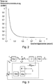
- Fig. 2 is a diagram for characterizing the controller performance
- Fig. 3 is a schematic representation of a control arrangement for a test bench with anti-wind-up structure.
- At least one load machine is provided on a test bench, usually an asynchronous machine fed by a frequency converter, which is coupled to the test object of the internal combustion engine via an elastic shaft.
- Input variables are the accelerator pedal on the drive side and the (positive or negative) load torque setpoint of the electrical machine on the load side. The combination of both resulting torques then sets the effective speed via the inertia and resistance.
- the engine is now to be operated on the test bench at the desired operating point, in most cases this operating point is expressed in a combination of speed and engine torque.
- the dynamics and accuracy of setting an operating point is particularly important.
- a measure of this dynamics and accuracy is the performance, which is defined as the reciprocal mean square deviation between the reference signal and the actually set value of the reference variable, which is also scaled to the standard performance.
- the standard performance is the reciprocal mean square deviation between the reference signal and the actually set value of the reference variable, which can be achieved with the test bench configuration used.
- the frequency distribution of the speed and torque references to be traced, the dynamic limits of the internal combustion engine, the limitations of the test bench hardware, i.e. especially the brake machine and the transmission shaft, as well as the exploitation of these limits, are decisive, for which the test bench control is particularly important responsible for. Since the specifications for the speed and torque curve can be freely selected, it is not always immediately clear whether they can also be implemented with the desired accuracy with the specific test setup. However, it is important that the machines are operated within the performance limits during the tests, otherwise the test may be misleading or it may appear that the test bench controller is not working properly.
- the weighting between the two variables can now be changed.
- the reserve of the performance brake is used to follow the specified speed as well as possible. This is at the expense of the actual torque curve, like the dash-dotted line in Fig. 1 shows.
- the reserve of the power brake can also be used to regulate the torque as best as possible, which is at the expense of the speed control, as the curve shown in dashed lines shows.
- the weighting is preferably infinitely adjustable, but could also take place in fixed, predetermined stages, for which the control device is equipped with an operating element for adjusting the weighting.
- This control element can of course also be implemented via a graphical user interface, for example shown as a slider, with which a stepless adjustment of the weighting from speed-controlled control to torque-controlled control is possible.
- a graphical user interface for example shown as a slider, with which a stepless adjustment of the weighting from speed-controlled control to torque-controlled control is possible.
- the manipulated variables required for an exact follow-up control of these modified courses are preferably also automatically calculated at the same time.
- the line shown shows the at best achievable controller performance for the in Fig. 1 shown change of working point.
- the performance limits of the test bench are preferably calculated automatically after an offline identification has been carried out.
- a feedback part ensures the necessary robustness and stability when regulating the test bench, this feedback part preferably being calculated automatically and coordinated with the weighting of the slider.
- this feedback part preferably being calculated automatically and coordinated with the weighting of the slider.
- This coupling can also be used intelligently in an "anti-wind-up” control.
- a possible “anti-wind-up” structure is in Fig. 3 shown schematically, with û the limited manipulated variable.
- An essential feature of this structure is the feedback of the difference between the value output by the controller and the permitted value. The exact execution of the part within the dashed frame is now essential for the behavior of the control loop in the case of manipulated variable restrictions.
- This part is designed in such a way that, if one input is restricted, the other is used to ensure the corresponding performance in the restricted case. It is therefore possible to support the other with an input that is not yet restricted.
- Non-limited manipulated variables are used to maintain the controller performance. This process can also be set continuously using a control knob or software-wise using a GUI. By restricting an input, it can happen that the performance is shifted from one controlled variable to another, which was not desirable in the original control loop without restrictions.
- the anti-windup structure should now make it possible to shift the reduced performance back to the original control variable in terms of weight in the limited case.
- the algorithm provided for this purpose is preferably calculated and set automatically after a brief identification.
- An automatically generated warning signal is particularly advantageous for the test bench operator if the operator specifies courses which cannot be implemented by the test bench configuration and thus may not be realistic.
- information can also be displayed as to which drive machine is operating within the limitation.
Landscapes
- Chemical & Material Sciences (AREA)
- Engineering & Computer Science (AREA)
- Combustion & Propulsion (AREA)
- Physics & Mathematics (AREA)
- General Physics & Mathematics (AREA)
- Testing Of Engines (AREA)
Description
- Die Erfindung betrifft einen Prüfstand für dynamische Prüfaufgaben an Verbrennungskraftmaschinen, mit einer vorzugsweise elektrischen Antriebs- und/oder Belastungseinrichtung, die mit einer Regeleinrichtung für die Anpassung und Regelung von Vorgabewerten für eine Drehzahl und einen Drehmomentverlauf gekoppelt ist, sowie ein Verfahren zum Betreiben eines Prüfstandes mit zumindest einer Antriebs- und/oder Belastungseinheit für dynamische Prüfaufgaben an Verbrennungskraftmaschinen, bei welchem Vorgabewerte für den Verlauf zumindest zweier Größen der Verbrennungsmaschine, vorzugsweise einer Drehzahl und eines Drehmoments, über eine Antriebs- und/oder Belastungseinheit eingeregelt werden.
- Eine hochdynamische und moderne Regeleinrichtung eines dynamischen Motorenprüfstandes erlaubt, dass einem beliebig vorgegebenen Verlauf von Drehzahl und Drehmoment nahezu perfekt gefolgt werden kann (
DE 102 47 347 A1 ). Dies ist aber immer nur dann möglich, wenn die Stellleistung der Antriebsmaschinen, d.h., der Brennkraftmaschine und der Leistungsbremse ausreichend ist. Diese ist aber jeweils begrenzt, was zu einer Eingrenzung der möglichen Verläufe führt. Da am Prüfstand zwei Antriebsmaschinen vorhanden sind, können zwei Ausgangsgrößen geregelt werden. Im der Regel sind das eine Drehzahl und ein Drehmoment. Bei der Drehzahl kann es sich um die Drehzahl der Leistungsbremse oder um die Drehzahl der Brennkraftmaschine handeln. Beim Moment ist entweder das Moment der Brennkraftmaschine, welches an der Kurbelwelle abgegeben wird, oder das Wellenmoment bzw. Belastungsmoment gemeint. Werden nun Verläufe dieser Größen vorgegeben, welche auf Grund der begrenzten Stellleistung nicht mehr eingeregelt werden können, dann müssen diese Verläufe so abgeändert werden, dass diese wiederum am Prüfstand realisiert werden können. - Durch Stellgrößenbegrenzung beim Prüfstand kann es bei der Feedbackregelung zu einem "Wind Up" Effekt kommen. Dieser Effekt lässt sich durch ein überhöhtes Überschwingen oder auch durch eine hohe Schwingneigung des geschlossenen Regelkreises erkennen und er führt zu einem Verlust der Reglerperformance. Aus diesem Grund werden Anti-Wind- Up Strukturen eingeführt welche diesen "Wind Up" Effekt unterbinden sollen. Diese Reglerergänzungen sind schon seit langem im Einsatz.
- Die Aufgabe der vorliegenden Erfindung waren daher in Prüfstand sowie ein Verfahren zu dessen Betrieb, bei welchen eine für die jeweilige Prüfaufgabe optimierte Anpassung und Regelung der durch eine Drehzahl und einen Drehmomentverlauf bestimmten Vorgabewerte möglich ist, sodass diese am Prüfstand bestmöglich dargestellt werden.
- Zur Lösung dieser Aufgabe ist der Prüfstand erfindungsgemäß dadurch gekennzeichnet, dass die Regeleinrichtung im Sinn einer Verstellung der Gewichtung von drehzahlgeführter Regelung auf drehmomentgeführter Regelung anpassbar ist.
- Vorteilhafterweise ist dazu die Regeleinrichtung mit einem Bedienelement zur Verstellung der Gewichtung verbunden.
- Gemäß einer bevorzugten Ausführungsform ist vorgesehen, dass das Bedienelement über eine graphische Benutzeroberfläche realisiert ist.
- Eine weitere Ausführungsform der Erfindung sieht vor, dass die Regeleinrichtung im Sinn einer stufenlosen Verstellung der Gewichtung anpassbar ist.
- Zur Lösung der eingangs gestellten Aufgabe ist das Verfahren dadurch gekennzeichnet, dass die Regeleinrichtung die verfügbare Stellleistung entsprechend einer vorgebbaren und veränderbaren Gewichtung auf die Verbrennungskraftmaschine und die Antriebs- und/oder Belastungseinheit aufteilt.
- Vorteilhafterweise ist dabei vorgesehen, dass bei einer die Leistungsreserven einer Arbeitsmaschine überschreitenden Regelungsanforderung die Leistungsreserven einer in ihren Leistungsgrenzen arbeitenden Arbeitsmaschine zur Unterstützung der anderen Arbeitsmaschine gemäß der vorgebbaren und veränderbaren Gewichtung eingesetzt wird.
- Gemäß einer bevorzugten Verfahrensvariante ist vorgesehen, dass das Erreichen der Leistungsgrenzen der Antriebsmaschinen überwacht und vor Überschreiten dieser Leistungsgrenzen die Vorgabewerte für zumindest eine der Größen derart abgeändert werden, dass beide Antriebsmaschinen innerhalb der Leistungsgrenzen bleiben.
- Natürlich kann auch auch vorgesehen sein, dass beide Vorgabewerte derart abgeändert werden, dass die Regeleinrichtung die verfügbare Stellleistung entsprechend der vorgegebenen Gewichtung aufteilt.
- Vorteilhafterweise werden dabei zusätzlich zur Anpassung der Sollverläufe auch gleichzeitig die dazu nötigen Stellgrößen für eine exakte Folgeregelung dieser abgeänderten Verläufe automatisch berechnet.
- Gemäß einer besonders vorteilhaften Variante der Erfindung ist weiters eine Anti-Wind-Up-Struktur, bei der die Rückführung der Differenz zwischen dem vom Regler ausgegebenen und dem erlaubten Wert verwendet wird, um die Stellleistung entsprechend der vorgebbare und veränderbare Gewichtung auf die Verbrennungskraftmaschine und die Antriebs- und/oder Belastungseinheit aufzuteilen.
- In der nachfolgenden Beschreibung soll die Erfindung unter Bezugnahme auf die beigefügten Abbildungen näher erläutert werden.
- Dabei zeigt die
Fig. 1 zwei Diagramme für einen Arbeitspunktwechsel außerhalb der Leistungsgrenzen der Prüfstandsanordnung,Fig. 2 ist ein Diagramm zur Charakterisierung der Reglerperformance, undFig. 3 ist eine schematische Darstellung einer Regelanordnung für einen Prüfstand mit Anti-Wind-Up-Struktur. - An einem Prüfstand ist zumindest eine Lastmaschine vorgesehen, meist eine durch einen Frequenzumrichter gespeiste Asynchronmaschine, welche mit dem Prüfling Verbrennungskraftmotor über eine elastische Welle gekoppelt ist. Eingangsgrößen sind antriebsseitig das Gaspedal und lastseitig das (positive oder negative) Lastmomentsollwert der elektrischen Maschine. Die Kombination beider daraus resultierenden Drehmomente stellt dann über die Trägheiten und Widerstände die effektive Drehzahl ein.
- Am Prüfstand soll nun der Motor im gewünschten Arbeitspunkt betrieben werden, wobei dieser Arbeitspunkt in den allermeisten Fällen in einer Kombination aus Drehzahl und Motormoment ausgedrückt wird. Besonders wichtig ist dabei die Dynamik und Genauigkeit der Einstellung eines Arbeitspunktes. Ein Maß für diese Dynamik und Genauigkeit ist die Performance, welche als die reziproke mittlere quadratische Abweichung zwischen dem Referenzsignal und dem tatsächlich eingestellten Wert der Bezugsgröße, welche außerdem auf die Normperformance skaliert ist, definiert ist. Die Normperformance ist dabei die reziproke mittlere quadratische Abweichung zwischen dem Referenzsignal und dem tatsächlich eingestellten Wert der Bezugsgröße, welche mit der verwendeten Prüfstandskonfiguration erreichbar ist.
- Für die Performance der Messung sind vor allem die Frequenzverteilung der nachzufahrenden Drehzahl- und Drehmomentreferenzen, die dynamischen Grenzen der Verbrennungskraftmaschine, die Beschränkungen der Prüfstandhardware, also vor allem der Bremsmaschine und der Übertragungswelle, sowie die Ausnützung dieser Grenzen, maßgeblich, wofür vor allem die Prüfstandsregelung verantwortlich ist. Da die Vorgaben für den Drehzahl- und Drehmomentverlauf frei gewählt werden können, ist es nicht immer unmittelbar klar, ob sie auch mit der gewünschten Genauigkeit mit dem konkreten Versuchsaufbau umsetzbar sind. Wichtig ist es aber, dass die Maschinen während der Versuche innerhalb der Performancegrenzen betrieben werden, andernfalls kann der Versuch irreführend sein, bzw. es kann den Anschein haben, dass die Prüfstandsregler nicht richtig funktionieren.
- Wenn ein Arbeitspunkt in möglichst kurzer Zeit, also unter Ausnützung der Performancegrenzen beider Maschinen geändert werden soll, gibt es im Wesentlichen zwei Extreme. Es kann der Drehzahlverlauf exakt nachgebildet werden, wofür beide Maschinen in die gleiche Richtung mit maximalem Moment (d.h. an den Performancegrenzen) antreiben müssen, wodurch das Drehmoment nicht mehr geregelt werden kann. Oder es kann der Drehmomentverlauf genau nachgebildet werden, und das jeweilige Drehmoment kann sehr schnell durch eine Verdrehung der Welle eingestellt werden, was durch die Entwicklung der Drehzahldifferenz bestimmt wird. Damit sie richtig bleibt, müssen deshalb die Drehzahlen auf beiden Maschinen koordiniert ansteigen, wobei hier der langsamere Motor beschränkend wirkt.
- In
Fig. 1 sind ein derartiger Arbeitspunktwechsel sowie die beiden Extremfälle dargestellt. Die durchgezogene Linie soll der gewünschte Verlauf sein, der allerdings nicht machbar ist, hauptsächlich weil der Motor zu langsam ist. Dadurch, dass der Motor in der Begrenzung ist, reduziert sich die Anzahl der Freiheitsgrade. Die schnellere Leistungsbremse, kann nun nicht beide Größen gleichzeitig ausregeln. - Mit einer Regeleinrichtung aber, die im Sinn einer Verstellung der Gewichtung von drehzahlgeführter Regelung auf drehmomentgeführter Regelung anpassbar ist, kann nun die Gewichtung zwischen beiden Größen geändert werden. Für eine drehzahlorientierte Regelung wird die Reserve der Leistungsbremse dazu verwendet, um der vorgegebenen Drehzahl so gut wie möglich zu folgen. Das geht dann zu Lasten des tatsächlichen Drehmomentverlaufs, wie die strich-punktierte Linie in
Fig. 1 zeigt. In gleicher Weise kann aber auch die Reserve der Leistungsbremse dazu genutzt werden, um das Drehmoment so gut wie möglich zu regeln, was auf Kosten der Drehzahlreglung geht, wie der strichliert dargestellte Verlauf zeigt. Vorzugsweise ist die Gewichtung stufenlos einstellbar, könnte aber auch in fix vorgegebenen Stufen erfolgen, wofür die Regeleinrichtung mit einem Bedienelement zur Verstellung der Gewichtung ausgestattet ist. Dieses Bedienelement kann selbstverständlich auch über eine graphische Benutzeroberfläche realisiert, beispielsweise als Schieberegler dargestellt, sein, mit dem eine stufenlose Verstellung der Gewichtung von drehzahlgeführter Regelung auf drehmomentgeführter Regelung möglich ist. Zusätzlich zur Anpassung der Sollverläufe werden vorzugsweise auch gleichzeitig die dazu nötigen Stellgrößen für eine exakte Folgeregelung dieser abgeänderten Verläufe automatisch berechnet. - Die in
Fig. 2 dargestellte Linie zeigt die bestenfalls erreichbare Reglerperformance für den inFig. 1 gezeigten Arbeitspunktwechsel. Je nach Stellung des Bedienelementes für die Verstellung der Gewichtung wird man einen Punkt auf der grauen Linie erreichen können, d.h. man hat entweder einen kleinen Drehmomentenfehler, einen kleinen Drehzahlfehler oder einen Mischwert. Vorzugsweise werden die Performancegrenzen des Prüfstandes nach der Durchführung einer offline Identifikation automatisch berechnet. - Ein Feedbackteil sorgt bei der Regelung des Prüfstandes für die notwendige Robustheit und Stabilität, wobei dieser Feedbackteil vorzugsweise automatisch berechnet wird und mit der Gewichtung des Schiebereglers abgestimmt ist. Durch die oben erläuterten Stellgrößenbegrenzung beim Prüfstand kann es bei der Feedbackregelung zu einem "Wind Up" Effekt kommen, der sich durch überhöhtes Überschwingen oder auch durch eine hohe Schwingneigung des geschlossenen Regelkreises auswirkt und zu einem Verlust der Reglerperformance führt. Daher gibt es als Reglerergänzungen sogenannte Anti-Wind- Up Strukturen. Interne Kopplungsterme der Eingänge, z.B. Gaspedal bei der Verbrennungskraftmaschine und das Vorgabemoment bei der Leistungsbremse, führen dazu, dass ein Eingang beide Ausgänge des Systems, d.h. sowohl beispielsweise die Drehzahl der Verbrennungskraftmaschine oder der Leistungsbremse und das Drehmoment der Verbrennungskraftmaschine an der Kurbelwelle oder das Wellenmoment (Belastungsmoment) beeinflusst.
- Diese Kopplung kann aber auch bei einer "Anti-Wind-Up" Regelung intelligent ausgenutzt werden. Eine mögliche "Anti-Wind-Up" Struktur ist in
Fig. 3 schematisch dargestellt, wobei mit û die begrenzte Stellgröße bezeichnet ist. Ein wesentliches Merkmal dieser Struktur ist die Rückführung der Differenz zwischen dem vom Regler ausgegebenen und dem erlaubten Wert. Die genaue Ausführung des Teils innerhalb des strichlierten Rahmens ist nun wesentlich für das Verhalten des Regelkreises im Falle von Stellgrößenbeschränkungen. - Dieser Teil ist derart gestaltet, dass im Falle einer Beschränkung eines Eingangs, der andere dazu verwendet wird, um die Performance auch im beschränkten Fall entsprechend zu gewährleisten. Es besteht also die Möglichkeit, mit einem noch nicht beschränkten Eingang den anderen zu unterstützen. Nicht begrenzte Stellgrößen werden also dazu verwendet die Reglerperformance aufrecht zu halten. Auch dieser Vorgang kann stufenlos über einen Stellknopf oder softwaremäßig über ein GUI eingestellt werden. Durch die Beschränkung eines Eingangs kann es passieren, dass die Performance von einer Regelgröße zu einer anderen verlagert wird, was im ursprünglichen Regelkreis ohne Beschränkungen nicht erwünscht gewesen ist. Die Anti-Windup-Struktur soll es nun ermöglichen die zwar reduzierte Performance im beschränkten Fall gewichtungsmäßig zurück zur ursprünglichen Regelgröße zu verlagern. Vorzugsweise wird der dafür vorgesehene Algorithmus nach einer kurzen Identifikation automatisch berechnet und eingestellt.
- Besonders vorteilhaft ist ein automatisch generiertes Warnsignal für den Prüfstandsoperator, wenn dieser Verläufe vorgibt, welche von der Prüfstandskonfiguration nicht umgesetzt werden können und somit möglicherweise nicht realistisch sind. Zusätzlich zum Warnsignal kann dabei auch eine Information angezeigt werden, welche Antriebsmaschine in der Begrenzung arbeitet.
Claims (10)
- Prüfstand für dynamische Prüfaufgaben an Verbrennungskraftmaschinen, mit einer vorzugsweise elektrischen Antriebs- und/oder Belastungseinrichtung, die mit einer Regeleinrichtung für die Anpassung und Regelung von Vorgabewerten für eine Drehzahl und einen Drehmomentverlauf gekoppelt ist, dadurch gekennzeichnet, dass die Regeleinrichtung im Sinn einer Verstellung der Gewichtung von drehzahlgeführter Regelung auf drehmomentgeführter Regelung anpassbar ist.
- Prüfstand nach Anspruch 1, dadurch gekennzeichnet, dass die Regeleinrichtung mit einem Bedienelement zur Verstellung der Gewichtung verbunden ist.
- Prüfstand nach Anspruch 2, dadurch gekennzeichnet, dass das Bedienelement über eine graphische Benutzeroberfläche realisiert ist.
- Prüfstand nach einem der Ansprüche 1 bis 3, dadurch gekennzeichnet, dass die Regeleinrichtung im Sinn einer stufenlosen Verstellung der Gewichtung anpassbar ist.
- Verfahren zum Betreiben eines Prüfstandes mit zumindest einer Antriebs- und/oder Belastungseinheit für dynamische Prüfaufgaben an Verbrennungskraftmaschinen, bei welchem Vorgabewerte für den Verlauf zumindest zweier Größen der Verbrennungsmaschine, vorzugsweise einer Drehzahl und eines Drehmoments, über eine Antriebs- und/oder Belastungseinheit eingeregelt werden, dadurch gekennzeichnet, dass die Regeleinrichtung die verfügbare Stellleistung entsprechend einer vorgebbaren und veränderbaren Gewichtung auf die Verbrennungskraftmaschine und die Antriebs- und/oder Belastungseinheit aufteilt.
- Verfahren nach Anspruch 5, dadurch gekennzeichnet, dass bei einer die Leistungsreserven einer Arbeitsmaschine überschreitenden Regelungsanforderung die Leistungsreserven einer in ihren Leistungsgrenzen arbeitenden Arbeitsmaschine zur Unterstützung der anderen Arbeitsmaschine gemäß der vorgebbaren und veränderbaren Gewichtung eingesetzt wird.
- Verfahren nach Anspruch 5 oder 6, dadurch gekennzeichnet, dass das Erreichen der Leistungsgrenzen der Antriebsmaschinen überwacht und vor Überschreiten dieser Leistungsgrenzen die Vorgabewerte für zumindest eine der Größen derart abgeändert werden, dass beide Antriebsmaschinen innerhalb der Leistungsgrenzen bleiben.
- Verfahren nach einem der Ansprüche 5 bis 7, dadurch gekennzeichnet, dass beide Vorgabewerte derart abgeändert werden, dass die Regeleinrichtung die verfügbare Stellleistung entsprechend der vorgegebenen Gewichtung aufteilt.
- Verfahren nach einem der Ansprüche 7 oder 8, dadurch gekennzeichnet, dass zusätzlich zur Anpassung der Sollverläufe auch gleichzeitig die dazu nötigen Stellgrößen für eine exakte Folgeregelung dieser abgeänderten Verläufe automatisch berechnet werden.
- Verfahren nach einem der Ansprüche 5 bis 9, dadurch gekennzeichnet, dass eine Anti-Wind-Up-Struktur vorgesehen ist, bei der die Rückführung der Differenz zwischen dem vom Regler ausgegebenen und dem erlaubten Wert verwendet wird, um die Stellleistung entsprechend der vorgebbare und veränderbare Gewichtung auf die Verbrennungskraftmaschine und die Antriebs- und/oder Belastungseinheit aufzuteilen.
Applications Claiming Priority (1)
| Application Number | Priority Date | Filing Date | Title |
|---|---|---|---|
| ATA644/2011A AT509381B1 (de) | 2011-05-09 | 2011-05-09 | Prüfstand für dynamische prüfaufgaben an verbrennungskraftmaschinen, sowie verfahren zum betreiben eines derartigen prüfstandes |
Publications (2)
| Publication Number | Publication Date |
|---|---|
| EP2522978A1 EP2522978A1 (de) | 2012-11-14 |
| EP2522978B1 true EP2522978B1 (de) | 2020-02-12 |
Family
ID=44352372
Family Applications (1)
| Application Number | Title | Priority Date | Filing Date |
|---|---|---|---|
| EP12163277.2A Active EP2522978B1 (de) | 2011-05-09 | 2012-04-05 | Prüfstand für dynamische Prüfaufgaben an Verbrennungskraftmaschinen, sowie Verfahren zum Betreiben eines derartigen Prüfstandes |
Country Status (5)
| Country | Link |
|---|---|
| US (1) | US8770019B2 (de) |
| EP (1) | EP2522978B1 (de) |
| JP (1) | JP5793104B2 (de) |
| CN (1) | CN102778359B (de) |
| AT (1) | AT509381B1 (de) |
Families Citing this family (7)
| Publication number | Priority date | Publication date | Assignee | Title |
|---|---|---|---|---|
| JP5708704B2 (ja) * | 2013-05-15 | 2015-04-30 | 株式会社明電舎 | エンジンベンチシステム |
| US9719454B2 (en) | 2014-11-12 | 2017-08-01 | General Electric Company | Human machine interface (HMI) guided mechanical fuel system adjustment |
| JP6044649B2 (ja) * | 2015-01-19 | 2016-12-14 | 株式会社明電舎 | ダイナモメータシステムの制御装置 |
| US10113936B2 (en) * | 2015-06-01 | 2018-10-30 | Rolls-Royce Corporation | Closed-loop engine testing system |
| AT517689B1 (de) * | 2015-11-11 | 2017-04-15 | Avl List Gmbh | Verfahren zum Erstellen eines Prüfversuchs |
| JP6497408B2 (ja) * | 2017-04-14 | 2019-04-10 | 株式会社明電舎 | 電気慣性制御装置 |
| AT522260B1 (de) * | 2019-03-11 | 2021-08-15 | Avl List Gmbh | Verfahren und Regelungseinrichtung zur Regelung einer Drehzahl |
Citations (3)
| Publication number | Priority date | Publication date | Assignee | Title |
|---|---|---|---|---|
| DE10247349A1 (de) * | 2001-10-11 | 2003-05-08 | Meidensha Tokio Tokyo Kk | Motorprüfsystem mit einem durch das mu-Synteheseverfahren entworfenen Drehzahlregler |
| DE10247347A1 (de) * | 2001-11-08 | 2003-05-28 | Meidensha Tokio Tokyo Kk | Motorprüfsystem mit einem durch das mu-Syntheseverfahren entworfenen Drehmomentregler |
| DE102005035408A1 (de) * | 2005-07-28 | 2007-02-01 | Robert Bosch Gmbh | Verfahren zur Ermittlung zylinderindividueller Drehkenngrößen einer Welle eines Verbrennungsmotors |
Family Cites Families (16)
| Publication number | Priority date | Publication date | Assignee | Title |
|---|---|---|---|---|
| JPS6051656B2 (ja) * | 1980-04-24 | 1985-11-15 | 三菱電機株式会社 | 動力計システムの制御装置 |
| JPS5766340A (en) * | 1980-10-13 | 1982-04-22 | Toyota Motor Corp | Operating device for running sikulation of actual car |
| JPH0612312B2 (ja) * | 1984-07-19 | 1994-02-16 | 株式会社明電舍 | 電気動力計の電気的慣性補償装置 |
| JP2623758B2 (ja) * | 1988-09-05 | 1997-06-25 | 株式会社明電舎 | ディーゼルエンジンのトルク制御装置 |
| JPH0454430A (ja) * | 1990-06-22 | 1992-02-21 | Kubota Corp | エンジンの自動試験運転装置 |
| JP3175353B2 (ja) * | 1992-11-26 | 2001-06-11 | 株式会社明電舎 | 制御系の切換制御装置 |
| JPH0674951U (ja) * | 1993-03-27 | 1994-10-21 | 株式会社堀場製作所 | エンジンダイナモメータ装置 |
| JP3772722B2 (ja) * | 2001-10-11 | 2006-05-10 | 株式会社明電舎 | エンジンベンチシステム |
| JP2003207418A (ja) * | 2002-01-09 | 2003-07-25 | Meidensha Corp | エンジンベンチシステムの始動方式 |
| JP2005292014A (ja) * | 2004-04-02 | 2005-10-20 | Meidensha Corp | エンジンダイナモメータの制御装置 |
| AT7889U3 (de) * | 2005-06-15 | 2006-12-15 | Avl List Gmbh | Verfahren zur prüfung eines dynamischen drehmomenterzeugers und vorrichtung zur ermittlung des dynamischen verhaltens einer verbindungswelle |
| JP4862758B2 (ja) * | 2007-06-20 | 2012-01-25 | 株式会社明電舎 | ダイナモメータの制御装置 |
| JP4766039B2 (ja) * | 2007-11-30 | 2011-09-07 | 株式会社明電舎 | エンジンベンチシステムの制御方式 |
| AT10182U3 (de) * | 2008-05-26 | 2009-05-15 | Avl List Gmbh | Verfahren zur überwachung von leistungsprüfständen, sowie leistungsprüfstand |
| JP5136247B2 (ja) * | 2008-07-10 | 2013-02-06 | 株式会社明電舎 | エンジンベンチシステムの動力計制御方式 |
| AT10301U3 (de) * | 2008-09-01 | 2009-09-15 | Avl List Gmbh | Verfahren und regelanordnung zur regelung einer regelstrecke mit sich wiederholendem arbeitszyklus |
-
2011
- 2011-05-09 AT ATA644/2011A patent/AT509381B1/de not_active IP Right Cessation
-
2012
- 2012-04-05 EP EP12163277.2A patent/EP2522978B1/de active Active
- 2012-04-23 JP JP2012097289A patent/JP5793104B2/ja not_active Expired - Fee Related
- 2012-05-04 US US13/464,519 patent/US8770019B2/en not_active Expired - Fee Related
- 2012-05-09 CN CN201210142602.1A patent/CN102778359B/zh not_active Expired - Fee Related
Patent Citations (3)
| Publication number | Priority date | Publication date | Assignee | Title |
|---|---|---|---|---|
| DE10247349A1 (de) * | 2001-10-11 | 2003-05-08 | Meidensha Tokio Tokyo Kk | Motorprüfsystem mit einem durch das mu-Synteheseverfahren entworfenen Drehzahlregler |
| DE10247347A1 (de) * | 2001-11-08 | 2003-05-28 | Meidensha Tokio Tokyo Kk | Motorprüfsystem mit einem durch das mu-Syntheseverfahren entworfenen Drehmomentregler |
| DE102005035408A1 (de) * | 2005-07-28 | 2007-02-01 | Robert Bosch Gmbh | Verfahren zur Ermittlung zylinderindividueller Drehkenngrößen einer Welle eines Verbrennungsmotors |
Also Published As
| Publication number | Publication date |
|---|---|
| CN102778359B (zh) | 2015-06-17 |
| AT509381A2 (de) | 2011-08-15 |
| CN102778359A (zh) | 2012-11-14 |
| JP2012237747A (ja) | 2012-12-06 |
| US8770019B2 (en) | 2014-07-08 |
| US20120285228A1 (en) | 2012-11-15 |
| JP5793104B2 (ja) | 2015-10-14 |
| EP2522978A1 (de) | 2012-11-14 |
| AT509381A3 (de) | 2011-11-15 |
| AT509381B1 (de) | 2012-04-15 |
Similar Documents
| Publication | Publication Date | Title |
|---|---|---|
| AT509381B1 (de) | Prüfstand für dynamische prüfaufgaben an verbrennungskraftmaschinen, sowie verfahren zum betreiben eines derartigen prüfstandes | |
| WO2014111177A1 (de) | Verfahren zur antriebsregelung sowie nach dem verfahren arbeitende regelungseinrichtung | |
| DE102015013283B4 (de) | Vorrichtung und Verfahren zum Steuern einer Werkzeugmaschine, um einen synchronisierten Betrieb einer Spindelachse und Vorschubachse zu steuern | |
| EP2913502A1 (de) | Verfahren zum Betrieb eines mit einem Generator gekoppelten Verbrennungsmotors und Vorrichtung zur Durchführung des Verfahrens | |
| DE112020003095T5 (de) | Parametereinstellungsverfahren | |
| DE102009038155B4 (de) | Servomotorsteuergerät | |
| DE112012001498B4 (de) | CVT-Steuerung unter Verwendung von zustandsraumbasierter Kennfeldermittlung | |
| DE102014226634B3 (de) | Verfahren zum Betreiben eines hydraulischen Antriebs, Recheneinheit, Computerprogramm und maschinenlesbares Speichermedium | |
| EP1916416B1 (de) | Verfahren zum Betreiben einer Windenergieanlage | |
| AT512550B1 (de) | Verfahren zur Dämpfung von Schwingungen | |
| EP2874547B1 (de) | Antriebssteuereinrichtung und -verfahren für ein chirurgisches motorensystem | |
| DE102017217278A1 (de) | Motorsteuerungs-vorrichtung, motorsteuerungs-verfahren und motorsteuerungs-programm | |
| DE102018000519B4 (de) | Vorrichtung und Verfahren zum Steuern einer Werkzeugmaschine, um einen synchronisierten Betrieb einer Spindelachse und Vorschubachse zu steuern | |
| EP4402371B1 (de) | Verfahren für einen hydraulischen antrieb, steuereinheit, computerprogramm, und maschinenlesbares speichermedium | |
| DE102009045183A1 (de) | Scheibenwischvorrichtung | |
| DE112011105322T5 (de) | Steuereinrichtung für eine Brennkraftmaschine mit Aufladegerät | |
| EP4081871B1 (de) | Steuerungsverfahren für ein teilelektronisches system | |
| EP4299904B1 (de) | Verfahren zur regelung von drehzahlvariablen fluidpumpen | |
| DE3609399C2 (de) | ||
| DE102022205233B4 (de) | Verfahren zum Betreiben eines Elektrohydraulikaggregats | |
| DE102022208574A1 (de) | Verfahren zum Betreiben eines hydraulischen Antriebs einer Maschine und hydraulischer Antrieb | |
| EP3223094A1 (de) | Steuereinrichtung für eine cnc-fräsmaschine | |
| EP3043467A1 (de) | Regelung einer Antriebsvorrichtung | |
| WO2020182895A1 (de) | Verfahren und regelungseinrichtung zur regelung einer drehzahl | |
| EP4552793A1 (de) | Haltesystem zur vorrübergehenden halterung eines werkstücks, verfahren zur anpassung einer halterungskraft bei einer halterungsanordnung, computerprogramm und vorrichtung zur datenverarbeitung |
Legal Events
| Date | Code | Title | Description |
|---|---|---|---|
| PUAI | Public reference made under article 153(3) epc to a published international application that has entered the european phase |
Free format text: ORIGINAL CODE: 0009012 |
|
| AK | Designated contracting states |
Kind code of ref document: A1 Designated state(s): AL AT BE BG CH CY CZ DE DK EE ES FI FR GB GR HR HU IE IS IT LI LT LU LV MC MK MT NL NO PL PT RO RS SE SI SK SM TR |
|
| AX | Request for extension of the european patent |
Extension state: BA ME |
|
| 17P | Request for examination filed |
Effective date: 20130507 |
|
| STAA | Information on the status of an ep patent application or granted ep patent |
Free format text: STATUS: EXAMINATION IS IN PROGRESS |
|
| 17Q | First examination report despatched |
Effective date: 20161114 |
|
| REG | Reference to a national code |
Ref country code: DE Ref legal event code: R079 Ref document number: 502012015753 Country of ref document: DE Free format text: PREVIOUS MAIN CLASS: G01M0015040000 Ipc: G01M0015050000 |
|
| RIC1 | Information provided on ipc code assigned before grant |
Ipc: G01M 15/05 20060101AFI20190809BHEP Ipc: G01M 15/04 20060101ALI20190809BHEP |
|
| GRAP | Despatch of communication of intention to grant a patent |
Free format text: ORIGINAL CODE: EPIDOSNIGR1 |
|
| STAA | Information on the status of an ep patent application or granted ep patent |
Free format text: STATUS: GRANT OF PATENT IS INTENDED |
|
| INTG | Intention to grant announced |
Effective date: 20190930 |
|
| GRAS | Grant fee paid |
Free format text: ORIGINAL CODE: EPIDOSNIGR3 |
|
| GRAA | (expected) grant |
Free format text: ORIGINAL CODE: 0009210 |
|
| STAA | Information on the status of an ep patent application or granted ep patent |
Free format text: STATUS: THE PATENT HAS BEEN GRANTED |
|
| AK | Designated contracting states |
Kind code of ref document: B1 Designated state(s): AL AT BE BG CH CY CZ DE DK EE ES FI FR GB GR HR HU IE IS IT LI LT LU LV MC MK MT NL NO PL PT RO RS SE SI SK SM TR |
|
| REG | Reference to a national code |
Ref country code: GB Ref legal event code: FG4D Free format text: NOT ENGLISH |
|
| REG | Reference to a national code |
Ref country code: CH Ref legal event code: EP |
|
| REG | Reference to a national code |
Ref country code: AT Ref legal event code: REF Ref document number: 1232767 Country of ref document: AT Kind code of ref document: T Effective date: 20200215 |
|
| REG | Reference to a national code |
Ref country code: DE Ref legal event code: R096 Ref document number: 502012015753 Country of ref document: DE |
|
| REG | Reference to a national code |
Ref country code: IE Ref legal event code: FG4D Free format text: LANGUAGE OF EP DOCUMENT: GERMAN |
|
| PG25 | Lapsed in a contracting state [announced via postgrant information from national office to epo] |
Ref country code: RS Free format text: LAPSE BECAUSE OF FAILURE TO SUBMIT A TRANSLATION OF THE DESCRIPTION OR TO PAY THE FEE WITHIN THE PRESCRIBED TIME-LIMIT Effective date: 20200212 Ref country code: FI Free format text: LAPSE BECAUSE OF FAILURE TO SUBMIT A TRANSLATION OF THE DESCRIPTION OR TO PAY THE FEE WITHIN THE PRESCRIBED TIME-LIMIT Effective date: 20200212 Ref country code: NO Free format text: LAPSE BECAUSE OF FAILURE TO SUBMIT A TRANSLATION OF THE DESCRIPTION OR TO PAY THE FEE WITHIN THE PRESCRIBED TIME-LIMIT Effective date: 20200512 |
|
| REG | Reference to a national code |
Ref country code: LT Ref legal event code: MG4D |
|
| REG | Reference to a national code |
Ref country code: NL Ref legal event code: MP Effective date: 20200212 |
|
| PG25 | Lapsed in a contracting state [announced via postgrant information from national office to epo] |
Ref country code: SE Free format text: LAPSE BECAUSE OF FAILURE TO SUBMIT A TRANSLATION OF THE DESCRIPTION OR TO PAY THE FEE WITHIN THE PRESCRIBED TIME-LIMIT Effective date: 20200212 Ref country code: LV Free format text: LAPSE BECAUSE OF FAILURE TO SUBMIT A TRANSLATION OF THE DESCRIPTION OR TO PAY THE FEE WITHIN THE PRESCRIBED TIME-LIMIT Effective date: 20200212 Ref country code: HR Free format text: LAPSE BECAUSE OF FAILURE TO SUBMIT A TRANSLATION OF THE DESCRIPTION OR TO PAY THE FEE WITHIN THE PRESCRIBED TIME-LIMIT Effective date: 20200212 Ref country code: IS Free format text: LAPSE BECAUSE OF FAILURE TO SUBMIT A TRANSLATION OF THE DESCRIPTION OR TO PAY THE FEE WITHIN THE PRESCRIBED TIME-LIMIT Effective date: 20200612 Ref country code: BG Free format text: LAPSE BECAUSE OF FAILURE TO SUBMIT A TRANSLATION OF THE DESCRIPTION OR TO PAY THE FEE WITHIN THE PRESCRIBED TIME-LIMIT Effective date: 20200512 Ref country code: GR Free format text: LAPSE BECAUSE OF FAILURE TO SUBMIT A TRANSLATION OF THE DESCRIPTION OR TO PAY THE FEE WITHIN THE PRESCRIBED TIME-LIMIT Effective date: 20200513 |
|
| PG25 | Lapsed in a contracting state [announced via postgrant information from national office to epo] |
Ref country code: NL Free format text: LAPSE BECAUSE OF FAILURE TO SUBMIT A TRANSLATION OF THE DESCRIPTION OR TO PAY THE FEE WITHIN THE PRESCRIBED TIME-LIMIT Effective date: 20200212 |
|
| PG25 | Lapsed in a contracting state [announced via postgrant information from national office to epo] |
Ref country code: SK Free format text: LAPSE BECAUSE OF FAILURE TO SUBMIT A TRANSLATION OF THE DESCRIPTION OR TO PAY THE FEE WITHIN THE PRESCRIBED TIME-LIMIT Effective date: 20200212 Ref country code: RO Free format text: LAPSE BECAUSE OF FAILURE TO SUBMIT A TRANSLATION OF THE DESCRIPTION OR TO PAY THE FEE WITHIN THE PRESCRIBED TIME-LIMIT Effective date: 20200212 Ref country code: CZ Free format text: LAPSE BECAUSE OF FAILURE TO SUBMIT A TRANSLATION OF THE DESCRIPTION OR TO PAY THE FEE WITHIN THE PRESCRIBED TIME-LIMIT Effective date: 20200212 Ref country code: SM Free format text: LAPSE BECAUSE OF FAILURE TO SUBMIT A TRANSLATION OF THE DESCRIPTION OR TO PAY THE FEE WITHIN THE PRESCRIBED TIME-LIMIT Effective date: 20200212 Ref country code: EE Free format text: LAPSE BECAUSE OF FAILURE TO SUBMIT A TRANSLATION OF THE DESCRIPTION OR TO PAY THE FEE WITHIN THE PRESCRIBED TIME-LIMIT Effective date: 20200212 Ref country code: PT Free format text: LAPSE BECAUSE OF FAILURE TO SUBMIT A TRANSLATION OF THE DESCRIPTION OR TO PAY THE FEE WITHIN THE PRESCRIBED TIME-LIMIT Effective date: 20200705 Ref country code: DK Free format text: LAPSE BECAUSE OF FAILURE TO SUBMIT A TRANSLATION OF THE DESCRIPTION OR TO PAY THE FEE WITHIN THE PRESCRIBED TIME-LIMIT Effective date: 20200212 Ref country code: ES Free format text: LAPSE BECAUSE OF FAILURE TO SUBMIT A TRANSLATION OF THE DESCRIPTION OR TO PAY THE FEE WITHIN THE PRESCRIBED TIME-LIMIT Effective date: 20200212 Ref country code: LT Free format text: LAPSE BECAUSE OF FAILURE TO SUBMIT A TRANSLATION OF THE DESCRIPTION OR TO PAY THE FEE WITHIN THE PRESCRIBED TIME-LIMIT Effective date: 20200212 |
|
| REG | Reference to a national code |
Ref country code: DE Ref legal event code: R097 Ref document number: 502012015753 Country of ref document: DE |
|
| PG25 | Lapsed in a contracting state [announced via postgrant information from national office to epo] |
Ref country code: MC Free format text: LAPSE BECAUSE OF FAILURE TO SUBMIT A TRANSLATION OF THE DESCRIPTION OR TO PAY THE FEE WITHIN THE PRESCRIBED TIME-LIMIT Effective date: 20200212 |
|
| REG | Reference to a national code |
Ref country code: CH Ref legal event code: PL |
|
| PLBE | No opposition filed within time limit |
Free format text: ORIGINAL CODE: 0009261 |
|
| STAA | Information on the status of an ep patent application or granted ep patent |
Free format text: STATUS: NO OPPOSITION FILED WITHIN TIME LIMIT |
|
| 26N | No opposition filed |
Effective date: 20201113 |
|
| PG25 | Lapsed in a contracting state [announced via postgrant information from national office to epo] |
Ref country code: CH Free format text: LAPSE BECAUSE OF NON-PAYMENT OF DUE FEES Effective date: 20200430 Ref country code: LU Free format text: LAPSE BECAUSE OF NON-PAYMENT OF DUE FEES Effective date: 20200405 Ref country code: LI Free format text: LAPSE BECAUSE OF NON-PAYMENT OF DUE FEES Effective date: 20200430 |
|
| REG | Reference to a national code |
Ref country code: BE Ref legal event code: MM Effective date: 20200430 |
|
| PG25 | Lapsed in a contracting state [announced via postgrant information from national office to epo] |
Ref country code: PL Free format text: LAPSE BECAUSE OF FAILURE TO SUBMIT A TRANSLATION OF THE DESCRIPTION OR TO PAY THE FEE WITHIN THE PRESCRIBED TIME-LIMIT Effective date: 20200212 Ref country code: SI Free format text: LAPSE BECAUSE OF FAILURE TO SUBMIT A TRANSLATION OF THE DESCRIPTION OR TO PAY THE FEE WITHIN THE PRESCRIBED TIME-LIMIT Effective date: 20200212 Ref country code: BE Free format text: LAPSE BECAUSE OF NON-PAYMENT OF DUE FEES Effective date: 20200430 |
|
| PG25 | Lapsed in a contracting state [announced via postgrant information from national office to epo] |
Ref country code: IE Free format text: LAPSE BECAUSE OF NON-PAYMENT OF DUE FEES Effective date: 20200405 |
|
| PGFP | Annual fee paid to national office [announced via postgrant information from national office to epo] |
Ref country code: FR Payment date: 20210421 Year of fee payment: 10 Ref country code: IT Payment date: 20210430 Year of fee payment: 10 Ref country code: DE Payment date: 20210421 Year of fee payment: 10 |
|
| PGFP | Annual fee paid to national office [announced via postgrant information from national office to epo] |
Ref country code: GB Payment date: 20210415 Year of fee payment: 10 Ref country code: AT Payment date: 20210420 Year of fee payment: 10 |
|
| PG25 | Lapsed in a contracting state [announced via postgrant information from national office to epo] |
Ref country code: TR Free format text: LAPSE BECAUSE OF FAILURE TO SUBMIT A TRANSLATION OF THE DESCRIPTION OR TO PAY THE FEE WITHIN THE PRESCRIBED TIME-LIMIT Effective date: 20200212 Ref country code: MT Free format text: LAPSE BECAUSE OF FAILURE TO SUBMIT A TRANSLATION OF THE DESCRIPTION OR TO PAY THE FEE WITHIN THE PRESCRIBED TIME-LIMIT Effective date: 20200212 Ref country code: CY Free format text: LAPSE BECAUSE OF FAILURE TO SUBMIT A TRANSLATION OF THE DESCRIPTION OR TO PAY THE FEE WITHIN THE PRESCRIBED TIME-LIMIT Effective date: 20200212 |
|
| PG25 | Lapsed in a contracting state [announced via postgrant information from national office to epo] |
Ref country code: MK Free format text: LAPSE BECAUSE OF FAILURE TO SUBMIT A TRANSLATION OF THE DESCRIPTION OR TO PAY THE FEE WITHIN THE PRESCRIBED TIME-LIMIT Effective date: 20200212 Ref country code: AL Free format text: LAPSE BECAUSE OF FAILURE TO SUBMIT A TRANSLATION OF THE DESCRIPTION OR TO PAY THE FEE WITHIN THE PRESCRIBED TIME-LIMIT Effective date: 20200212 |
|
| REG | Reference to a national code |
Ref country code: DE Ref legal event code: R119 Ref document number: 502012015753 Country of ref document: DE |
|
| REG | Reference to a national code |
Ref country code: AT Ref legal event code: MM01 Ref document number: 1232767 Country of ref document: AT Kind code of ref document: T Effective date: 20220405 |
|
| GBPC | Gb: european patent ceased through non-payment of renewal fee |
Effective date: 20220405 |
|
| PG25 | Lapsed in a contracting state [announced via postgrant information from national office to epo] |
Ref country code: GB Free format text: LAPSE BECAUSE OF NON-PAYMENT OF DUE FEES Effective date: 20220405 Ref country code: FR Free format text: LAPSE BECAUSE OF NON-PAYMENT OF DUE FEES Effective date: 20220430 Ref country code: DE Free format text: LAPSE BECAUSE OF NON-PAYMENT OF DUE FEES Effective date: 20221103 Ref country code: AT Free format text: LAPSE BECAUSE OF NON-PAYMENT OF DUE FEES Effective date: 20220405 |
|
| PG25 | Lapsed in a contracting state [announced via postgrant information from national office to epo] |
Ref country code: IT Free format text: LAPSE BECAUSE OF NON-PAYMENT OF DUE FEES Effective date: 20220405 |