EP2522442A1 - Flexure member manufacturing method and flexture member manufacturing device - Google Patents
Flexure member manufacturing method and flexture member manufacturing device Download PDFInfo
- Publication number
- EP2522442A1 EP2522442A1 EP11731814A EP11731814A EP2522442A1 EP 2522442 A1 EP2522442 A1 EP 2522442A1 EP 11731814 A EP11731814 A EP 11731814A EP 11731814 A EP11731814 A EP 11731814A EP 2522442 A1 EP2522442 A1 EP 2522442A1
- Authority
- EP
- European Patent Office
- Prior art keywords
- metal material
- steel tube
- induction heating
- heating coil
- sec
- Prior art date
- Legal status (The legal status is an assumption and is not a legal conclusion. Google has not performed a legal analysis and makes no representation as to the accuracy of the status listed.)
- Granted
Links
Images



Classifications
-
- C—CHEMISTRY; METALLURGY
- C21—METALLURGY OF IRON
- C21D—MODIFYING THE PHYSICAL STRUCTURE OF FERROUS METALS; GENERAL DEVICES FOR HEAT TREATMENT OF FERROUS OR NON-FERROUS METALS OR ALLOYS; MAKING METAL MALLEABLE, e.g. BY DECARBURISATION OR TEMPERING
- C21D9/00—Heat treatment, e.g. annealing, hardening, quenching or tempering, adapted for particular articles; Furnaces therefor
- C21D9/08—Heat treatment, e.g. annealing, hardening, quenching or tempering, adapted for particular articles; Furnaces therefor for tubular bodies or pipes
-
- B—PERFORMING OPERATIONS; TRANSPORTING
- B21—MECHANICAL METAL-WORKING WITHOUT ESSENTIALLY REMOVING MATERIAL; PUNCHING METAL
- B21D—WORKING OR PROCESSING OF SHEET METAL OR METAL TUBES, RODS OR PROFILES WITHOUT ESSENTIALLY REMOVING MATERIAL; PUNCHING METAL
- B21D7/00—Bending rods, profiles, or tubes
- B21D7/12—Bending rods, profiles, or tubes with program control
-
- B—PERFORMING OPERATIONS; TRANSPORTING
- B21—MECHANICAL METAL-WORKING WITHOUT ESSENTIALLY REMOVING MATERIAL; PUNCHING METAL
- B21D—WORKING OR PROCESSING OF SHEET METAL OR METAL TUBES, RODS OR PROFILES WITHOUT ESSENTIALLY REMOVING MATERIAL; PUNCHING METAL
- B21D7/00—Bending rods, profiles, or tubes
- B21D7/16—Auxiliary equipment, e.g. for heating or cooling of bends
-
- C—CHEMISTRY; METALLURGY
- C21—METALLURGY OF IRON
- C21D—MODIFYING THE PHYSICAL STRUCTURE OF FERROUS METALS; GENERAL DEVICES FOR HEAT TREATMENT OF FERROUS OR NON-FERROUS METALS OR ALLOYS; MAKING METAL MALLEABLE, e.g. BY DECARBURISATION OR TEMPERING
- C21D1/00—General methods or devices for heat treatment, e.g. annealing, hardening, quenching or tempering
- C21D1/34—Methods of heating
- C21D1/42—Induction heating
-
- C—CHEMISTRY; METALLURGY
- C21—METALLURGY OF IRON
- C21D—MODIFYING THE PHYSICAL STRUCTURE OF FERROUS METALS; GENERAL DEVICES FOR HEAT TREATMENT OF FERROUS OR NON-FERROUS METALS OR ALLOYS; MAKING METAL MALLEABLE, e.g. BY DECARBURISATION OR TEMPERING
- C21D11/00—Process control or regulation for heat treatments
-
- C—CHEMISTRY; METALLURGY
- C21—METALLURGY OF IRON
- C21D—MODIFYING THE PHYSICAL STRUCTURE OF FERROUS METALS; GENERAL DEVICES FOR HEAT TREATMENT OF FERROUS OR NON-FERROUS METALS OR ALLOYS; MAKING METAL MALLEABLE, e.g. BY DECARBURISATION OR TEMPERING
- C21D9/00—Heat treatment, e.g. annealing, hardening, quenching or tempering, adapted for particular articles; Furnaces therefor
- C21D9/52—Heat treatment, e.g. annealing, hardening, quenching or tempering, adapted for particular articles; Furnaces therefor for wires; for strips ; for rods of unlimited length
- C21D9/54—Furnaces for treating strips or wire
- C21D9/56—Continuous furnaces for strip or wire
- C21D9/60—Continuous furnaces for strip or wire with induction heating
-
- Y—GENERAL TAGGING OF NEW TECHNOLOGICAL DEVELOPMENTS; GENERAL TAGGING OF CROSS-SECTIONAL TECHNOLOGIES SPANNING OVER SEVERAL SECTIONS OF THE IPC; TECHNICAL SUBJECTS COVERED BY FORMER USPC CROSS-REFERENCE ART COLLECTIONS [XRACs] AND DIGESTS
- Y02—TECHNOLOGIES OR APPLICATIONS FOR MITIGATION OR ADAPTATION AGAINST CLIMATE CHANGE
- Y02P—CLIMATE CHANGE MITIGATION TECHNOLOGIES IN THE PRODUCTION OR PROCESSING OF GOODS
- Y02P10/00—Technologies related to metal processing
- Y02P10/25—Process efficiency
Definitions
- This invention relates to a method and apparatus for manufacturing a bent member.
- Strength members, reinforcing members, and structural members made of metal are used in automobiles and various types of machinery. A high strength, a low weight, and a small size are demanded of these members.
- these members have been manufactured by welding of press worked steel parts, punching of thick steel plates, or forging of aluminum alloys. Decreases in the weight and size of bent members achieved by these manufacturing methods have reached a limit.
- Patent Document 1 the present applicant disclosed a manufacturing apparatus for a bent member.
- FIG 12 is an explanatory view schematically showing that manufacturing apparatus 0.
- the manufacturing apparatus 0 manufactures a bent member 8 by bending a metal tube 1 (in the following explanation, an example will be given of the case in which the metal tube is a steel tube) which is supported by a support mechanism 2 so as to be able to move in its axial direction, the bending being performed on the downstream side of the support mechanism 2 while feeding the steel tube 1 from the upstream side to the downstream side with a feed mechanism 3.
- an induction heating coil 5 rapidly carries out induction heating of the steel tube 1 being fed in the axial direction to a temperature range (to at least the Ac 3 point) at which the steel tube 1 can be locally quench-hardened.
- a water cooling mechanism 6 rapidly cools the steel tube 1 immediately downstream of the induction heating coil 5.
- a high temperature portion 1a which moves in the axial direction of the steel tube 1 is locally formed in the steel tube.
- the resistance to deformation of the high temperature portion 1a is markedly lower than the resistance to deformation of other portions.
- a movable roller die 4 has at least one roll pair 4a.
- the roll pair 4a supports the steel tube 1 while feeding it.
- the movable roller die 4 moves two-dimensionally or three-dimensionally while supporting the steel tube 1, thereby applying a bending moment to the high temperature portion 1a of the steel tube.
- the manufacturing apparatus 0 manufactures a bent member 8 having a desired shape and a high strength (such as a tensile strength of at least 780 MPa) by bending the steel tube 1 with a high operating efficiency by simple steps using relatively inexpensive components 2 - 6.
- a high strength such as a tensile strength of at least 780 MPa
- the manufacturing apparatus 0 In order for the manufacturing apparatus 0 to manufacture a bent member 8 having excellent dimensional accuracy, it is extremely important to form the high temperature portion 1a in a region which is narrow in the axial direction of the steel tube 1 and which is uniform in the circumferential direction of the steel tube 1.
- the present invention is based on the new finding that in a manufacturing apparatus 0, in order to stably form a high temperature portion 1a in a narrow region in the axial direction and uniformly in the circumferential direction of a steel tube 1, (a) when the steel tube 1 has a wall thickness of at most 2.0 mm, it is effective to make the feed speed V of the steel tube 1 a value of 5 - 150 mm/sec and to use an induction heating coil having one winding as the induction heating coil 5 and to supply the induction heating coil 5 with an alternating current with a current frequency of 5 - 100 kHz, and (b) when the wall thickness of the steel tube 1 is greater than 2.0 mm and at most 3.0 mm, it is effective to use an induction heating coil having two windings as the induction heating coil 5, and to adjust the current frequency f (kHz) of the induction heating coil 5 and the feed speed V (mm/sec) of the steel tube 1 so as to satisfy the relationships given by Equation (1): f ⁇ 3000/V and Equ
- the present invention is a method of manufacturing a bent member intermittently or continuously having in its lengthwise direction a bent portion which is bent three-dimensionally by supporting an elongated hollow metal material having a closed transverse cross-sectional shape at a first position while feeding it in its lengthwise direction, forming a high temperature portion which moves in the axial direction of the metal material by performing induction heating of the metal material with an induction heating coil at a second position located downstream of the first position in the feed direction of the metal material and cooling the heated metal material at a third position located downstream of the second position in the feed direction of the metal material, and applying a bending moment to the high temperature portion by three-dimensionally varying the position of a gripping mechanism which grips the metal material in a region downstream of the third position in the feed direction of the metal material, characterized in that when the metal material has a wall thickness of at most 2.0 mm, the feed speed of the metal material is made 5 - 150 mm/sec, an induction heating coil having 1 winding is used as the induction heating coil,
- the present invention is a manufacturing apparatus for a bent member having a feed mechanism for feeding an elongated, hollow metal material having a closed transverse cross-sectional shape in its lengthwise direction, a support mechanism for supporting the metal material being fed at a first position, a heating mechanism for performing induction heating of the metal material being fed at a second position located downstream of the first position in the feed direction of the metal material, a cooling mechanism for cooling the metal material at a third position located downstream of the second position in the feed direction of the metal material thereby locally forming in the metal material a high temperature portion which moves in the axial direction of the metal material, and a gripping mechanism for applying a bending moment to the high temperature portion by moving three-dimensionally while gripping the metal material being fed in a region located downstream of the third position in the feed direction of the metal material, characterized in that when the metal material has a wall thickness of at most 2.0 mm, the feed mechanism feeds the metal material at a speed V of 5 - 150 mm/sec, the heating mechanism has an
- a bent member may be manufactured under either of the above conditions.
- Figure 1 is an explanatory view schematically showing in simplified form the structure of an example of a manufacturing apparatus 10 according to the present invention.
- the manufacturing apparatus 10 has a feed mechanism 11, a support mechanism 13, a heating mechanism 14, a cooling mechanism 16, and a gripping mechanism 15. These components will be explained in sequence.
- the feed mechanism 11 feeds a metal material 1 in its lengthwise direction.
- the metal material 1 is an elongated hollow member having a closed cross-sectional shape.
- the metal material 1 is a steel tube.
- the present invention is not limited to the case in which the metal material is a steel tube 1.
- a hollow metal material having a transverse cross-sectional shape of a rectangle, an ellipse, an oblong shape, a polygon, or a combination of a polygon and a circle, or a combination of a polygon and an ellipse can be used in the same manner as a steel tube 1.
- An example of the feed mechanism 11 is a feed mechanism using an electric servo cylinder.
- the feed mechanism 11 is not restricted to a specific type.
- Known feed mechanisms such as a feed mechanism using a ball screw or a feed mechanism using a timing belt or a chain can be used equally well as the feed mechanism 11.
- the steel tube 1 is movably supported by a chuck 12 and is fed by the feed mechanism 11 at a predetermined feed speed V (mm/sec) in its axial direction (lengthwise direction).
- the chuck 12 supports the steel tube 1 in order to feed the steel tube 1.
- the chuck 12 may be omitted.
- the support mechanism 13 movably supports the steel tube 1 which is being fed in its axial direction by the feed mechanism 11 at a first position A.
- the support mechanism 13 is a fixed guide.
- the support mechanism 13 is not limited to a specific type of support mechanism.
- One or more pairs of opposing non-driven rolls may be used as the support mechanism 13.
- a known support mechanism can be used equally well as the support mechanism 13.
- the steel tube 1 passes the installation position A of the support mechanism 13 and is fed in its axial direction.
- the support mechanism 13 may be replaced by the chuck 12.
- the heating mechanism 14 performs induction heating of the steel tube 1 being fed.
- the heating mechanism 14 is disposed at a second position B located downstream of the first position A in the feed direction of the steel tube 1.
- the feed mechanism 11 feeds the steel tube 1 with a feed speed V of 5 - 150 mm/sec.
- the heating mechanism 14 has an induction heating coil 14a with 1 winding, and the induction heating coil 14a is supplied with an alternating current having a current frequency of 5 - 100 kHz.
- the heating mechanism 14 has an induction heating coil 14a with 2 windings.
- the feed mechanism 11 and the heating mechanism 14 adjust the feed speed V (mm/sec) of the steel tube 1 by the feed mechanism 11 and the current frequency f (kHz) of the alternating current supplied to the induction heating coil 14a so as to satisfy the relationships:
- An induction heating coil having 1 winding is not limited to an induction heating coil in which the coil body completely surrounds the periphery of the steel tube 1.
- An induction heating coil have 1 winding includes an induction heating coil having a coil body which surrounds most of the steel tube 1 but does not surround a portion of the outer periphery of the steel tube 1.
- an induction heating coil having a coil body which surrounds at least 70% of the outer periphery of the steel tube 1 falls within the scope of "an induction heating coil having 1 winding”.
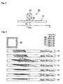
- Figure 2 is an explanatory view showing a model 30 for numerical analysis. As shown in Figure 2 , the numerical analysis model 30 has cylindrical two coordinates.
- the shape of the high temperature portion 31a formed when the wall thickness of the steel tube 31, the current frequency f of the current supplied to the induction heating coil 32, and the feed speed V of the steel tube 31 were varied was investigated by magnetic field analysis and heat transfer analysis.
- the induction heating coil 32 was constituted by a copper tube having a square transverse cross-sectional shape measuring 15 mm on a side, numerical analysis was carried out under the following conditions:
- the position for the start of cooling of the heated steel tube 31 was 10 mm downstream of the projected position 33 of the end of the induction heating coil 32.
- Figure 3 shows the results of numerical analysis of the temperature distribution of the steel tube 31 for the case in which the wall thickness of the steel tube 31 was 3 mm and the current frequency f was 25 kHz.
- Figure 3 shows the dependence of the high temperature portion of the steel tube 31 on the feed speed.
- the line at the upper portion of the steel tube 31 indicates the outer surface of the steel tube 31 and the line at the lower portion of the steel tube 31 indicates the inner surface of the steel tube 31.
- the resistance to deformation of a steel material greatly decreases in a temperature range of 800° C and above. Therefore, in this numerical analysis, the heated region was made one in which the temperature increased to at least 800° C. All calculations were carried out under conditions such that the maximum temperature of the outer surface of the steel tube 31 was 1000° C.
- the uniformity of temperature in the plate thickness direction is important, and particularly it is necessary to control the width of the region in which the temperature is at 800° C or above (referred to below as the effective heated width).
- the effective heated width (the region shown by A in Figure 3 ) becomes narrow.
- the effective heated width A becomes nearly 0. If the effective heated width A is 0, it becomes impossible to perform bending with good accuracy.
- the feed speed V of the steel tube 31 becomes 100 mm/sec or higher, the inner surface of the steel tube 31 can no longer be heated to at least 800° C and it becomes impossible to carry out bending.
- the feed speed V of the steel tube 31 is made at least 5 mm/sec to at most 150 mm/sec.
- Figure 5 is an explanatory view showing the results of analysis when current with a current frequency f of 25 kHz was supplied to an induction heating coil having 2 windings 31-1 and 31-2 and the feed speed V of the steel tube 31 was varied.
- Figure 6 is an explanatory view showing the results of analysis when the current frequency f of the current supplied to the induction heating coils having 2 windings 31-1 and 31-2 was varied and the steel tube 31 was fed at a speed of 100 mm/sec.
- the dash symbols (-) in Table 1 indicates that the effective heated width A is zero or higher with a wall thickness of at most 3 mm, namely, it indicates that a steel tube with a wall thickness of at most 3 mm can be subjected to bending.
- the numbers in Table 1 indicate the critical working thickness (mm); namely, the effective heat width A becomes zero when the wall thickness exceeds this value.
- the induction heating coil 32 is typically made of a copper alloy.
- the current which can be passed through the induction heating coil 32 depends upon the cross-sectional area of the induction heating coil 32 and the cooling method, but it is normally a maximum of 10,000 A. As shown in Table 1, in order to increase the feed speed V of the steel tube 31, it is necessary to lower the current frequency f. If the current frequency f is lowered, the current in the induction heating coil 32 increases.
- Table 2 shows the current (A) which needs to be supplied to an induction heating coil 32 having 1 winding in order to perform heating to 1000° C when a steel tube 31 has a wall thickness of 3 mm.
- the induction heating coil In order to solve this problem, it is effective for the induction heating coil to have 2 windings. By increasing the number of windings from 1 to 2, it is possible to decrease the current per winding, but the heated width in the axial direction of the steel tube 31 increases.
- Table 3 shows the results of numerical analysis of the current (A) necessary for heating a steel tube 31 to 1000° C when the induction heating coil has 2 winding and the wall thickness of the steel tube 31 is 3 mm.
- Table 4 shows the results of analysis of the region in which the effective heated width A is higher than zero when the induction heating coil has 2 windings.
- the symbols and numbers in Table 4 are the same as in Table 1.
- the heated width is greater than with 1 winding, so the conditions in which the effective heated width A can be guaranteed are expanded.
- Figure 5 shows the effective heated width A (mm) when the induction heating coil has one winding
- Figure 6 shows the effective heated width A (mm) when the induction heating coil has 2 windings.
- Table 5 V (mm/sec) f(kHz) 5 10 25 50 75 100 5 16.54 15.12 15.83 17.74 18.38 19.08 10 17.10 15.65 16.15 18.29 19.35 20.12 50 20.33 19.04 19.64 21.46 22.47 23.10 75 21.47 19.21 19.32 21.02 22.17 22.71 100 21.47 19.29 19.51 20.48 21.56 22.28 125 21.91 19.90 19.83 20.47 21.25 21.93 150 22.51 20.96 20.13 20.39 21.16 21.68
- the effective heated width A becomes at most 25 mm under all conditions with 1 winding, but as shown by the region surrounded by the dashed line in Table 6, when there are 2 windings, depending upon the conditions, the effective heated width A sometimes exceeds 30 mm.
- the effective heated width A is preferably as narrow as possible.
- the effective heated width A (mm) is preferably at most around 30 mm.
- using an induction heating coil 32 having 1 winding can decrease the effective heated width A (mm), whereby the dimensional accuracy of a bent member can be guaranteed.
- the feed speed V is preferably at most 150 mm/sec and the current frequency f is preferably from 25 kHz to 100 kHz.
- the wall thickness is greater than 2.0 mm and at most 3.0 mm, it is preferable to use an induction heating coil of 2 windings 32-1 and 32-2. In this case as well, it is preferable for the effective heated width A to be at most 30 mm in order to guarantee the dimensional accuracy of the bent member.
- Table 6 The relationship shown in Table 6 is illustrated by a graph in Figure 7 .
- the hollow circles in the graph of Figure 7 show the case in which the effective heated width A is at most 30 mm, and the solid squares show the case when the effective heated width A exceeds 30 mm.
- the effective width A can be made at most 30 mm if the current frequency f (kHz) and the feed speed V (mm) satisfy the relationship given by the approximate formula f ⁇ 3000V.
- the region in which the current can pass through the coil when an induction heating coil of 2 windings 32-1 and 32-2 is used is the region given by the approximate formula f ⁇ 0.08 V.
- Figure 9 is a graph showing the region in Figure 7 where the effective heated width A is at most around 30 mm in combination with the region in Figure 8 where the current can pass.
- the region in which the effective heated width A cannot be guaranteed regardless of how the current frequency f and the feed speed V are adjusted is shown by portion LP marked with a lattice (f ⁇ 25 kHz and V ⁇ 125 mm/sec).
- the steel tube 1 is fed by the feed mechanism 11 at a feed speed V of 5 - 150 mm/sec, and induction heating of the steel tube 1 is carried out using an induction heating coil 14a having 1 winding as the heating mechanism 14 and by supplying the induction heating coil 14a of 1 winding with an alternating current having a current frequency f of 5 - 100 kHz.
- an induction heating coil 14a having 2 windings is used as the heating mechanism 14, and the feed mechanism 11 and the heating mechanism 14 are preferably adjusted so that the feed speed V (mm/sec) of the steel tube 1 by the feed mechanism 11 and the current frequency f (kHz) of the alternating current supplied to the induction heating coil 14a satisfy the relationships f ⁇ 3000/V and f ⁇ 0.08 V, under the conditions 5 kHz ⁇ f ⁇ 100 kHz and 5 mm/sec ⁇ V ⁇ 150 mm/sec.
- the heated width A of the steel tube 1 slightly increases, but such a heating coil can be applied even when the wall thickness of the steel tube 1 is at most 2.0 mm.
- heating the steel tube 1 with at least one additional heating mechanism disposed on the upstream side of heating mechanism 14, it is possible to heat the steel tube 1 two or more times or to non-uniformly heat a portion of the steel tube 1 in the circumferential direction.
- the cooling mechanism 16 is disposed at a third position C on the downstream side of the second position B in the feed direction of the steel tube 1.
- the cooling mechanism 16 cools the heated steel tube 1.
- a high temperature portion 1a which moves in the axial direction of the steel tube 1 is locally formed.
- the high temperature portion 1a has a resistance to deformation which is much lower than that of other portions.
- the cooling mechanism 16 can be any mechanism which can cool the steel tube 1 at a desired cooling speed, and it is not limited to a specific type of cooling mechanism.
- an example of the cooling mechanism is a water cooling mechanism which cools the steel tube 1 by spraying cooling water at a predetermined position on the outer peripheral surface of the steel tube 1.
- cooling water is sprayed so as to be sloped toward the feed direction of the steel tube 1.
- the gripping mechanism 15 is disposed in a region D downstream of the third position C in the feed direction of the steel tube 1.
- the gripping mechanism 15 moves three-dimensionally in a direction including at least the feed direction of the steel tube 1 within a workspace including a space on the upstream side of the third position C in the feed direction of the steel tube 1.
- the gripping mechanism 15 imparts a bending moment to the high temperature portion 1a formed in the steel tube 1.
- a chuck mechanism is used as the gripping mechanism 15.
- the gripping mechanism 15 which can move three-dimensionally can of course move two-dimensionally.
- the gripping mechanism 15 By moving the gripping mechanism 15 two-dimensionally, it is possible to carry out bending in which the bending direction varies two-dimensionally and to manufacture a bent member having a bending direction which varies two-dimensionally such as is the case with S-shaped bending.
- the workspace means a three-dimensional space defined by Equations (3), (4), and (5).
- x ⁇ 0 , and y 0 or y ⁇ 0.5 ⁇ D , and 0 ⁇ ⁇ ⁇ 360 ⁇ ° x 2 + y - R min 2 ⁇ R min 2 x 2 + y + R min 2 ⁇ R min 2 - 0.5 ⁇ D - R min 2 + 0.5 ⁇ D + R min 2
- D means the smallest outer dimension (mm) of the bent member
- R min means the smallest radius of curvature (mm) of the bent member
- x, y, and ⁇ are cylindrical coordinates having the second position as an origin, wherein a positive value for x is in the instantaneous feed direction of the bent member, y is in the direction perpendicular to x in a horizontal plane, and ⁇ is the angle in the circumferential direction.
- the gripping mechanism 15 bends the steel tube 1 by moving three-dimensionally within the workspace, whereby a bent member having bent portions intermittently or continuously in its lengthwise direction is manufactured.
- the workspace is a subjective space, so objects such as various mechanisms can be present in the workspace.
- the gripping mechanism 15 includes a body 17 with a pillar-like outer shape and a moving mechanism 20.
- the body 17 is constituted by a hollow member.
- the hollow member has an inner peripheral surface having a shape fitting the outer peripheral surface of the steel tube 1.
- the body 17 grips the steel tube 1 by contacting the outer surface of the end of the steel tube 1.
- the body 17 may be constituted by a tubular member having an outer peripheral surface with a shape fitting the inner peripheral surface of the steel tube 1. In this case, the body 17 grips the steel tube 1 by being inserted into the end of the steel tube 1.
- the moving mechanism 20 is constituted by a first base 18 and a second base 19.
- the body 17 is mounted on the first base 18, and the first base 18 can move in a direction perpendicular to the feed direction of the steel tube at the first position A (in the vertical direction in Figure 1 ).
- the second base 19 is disposed so as to be able to move the first base 18 in the feed direction.
- Movement of the first base 18 and the second base 19 is individually carried out by a ball screw and a drive motor.
- the body 17 can be moved two-dimensionally in a horizontal plane by the moving mechanism 20.
- Reference number 22 in Figure 1 indicates an x axis tilt motor
- reference number 23 indicates an x axis shift motor
- reference number 24 indicates a y axis tilt motor
- reference number 25 indicates a y axis shift motor
- reference number 26 indicates a z axis tilt motor
- reference number 27 indicates an x axis shift motor.
- the body 17 may be supported by an articulated robot having joints which can rotate around at least one axis.
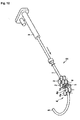
- Figure 10 is an explanatory view schematically showing the structure of a manufacturing apparatus 10-1 using an articulated robot 21
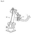
- Figure 11 is an explanatory view showing the articulated robot 21.
- the articulated robot 21 can easily support the body 17 so as to be able to move three-dimensionally in a direction including at least the feed direction of the steel tube 1.
- an elongated steel tube 1 is supported at the first position A by the support mechanism 13 and is fed in its lengthwise direction by the feed mechanism 11.
- the feed mechanism 11 feeds the steel tube 1 with a feed speed V of 5 - 150 mm/sec, and by supplying an alternating current with a current frequency V of 5 - 100 kHz to the induction heating coil 14a of 1 winding which constitutes the heating mechanism 14 disposed at the second position B, the steel tube is subjected to induction heating.
- the steel tube 1 undergoes induction heating by controlling the feed speed V (mm/sec) of the steel tube 1 by the feed mechanism 11 and the current frequency f (kHz) of the alternating current supplied to the induction heating coil 14a of 2 winding which constitutes the heating mechanism 14 so as to satisfy the relationships f ⁇ 3000/V and f ⁇ 0.08 V.
- a high temperature portion 1a is formed in the steel tube 1 by cooling the steel tube 1 by the cooling mechanism 16 at the third position C.
- region D the position of the gripping mechanism 15 which grips the steel tube 1 is varied three-dimensionally in a direction including at least the feed direction of the steel tube 1 within the workspace to impart a bending moment to the high temperature portion 1a of the steel tube 1.
- a bent member can be continuously manufactured by disposing the manufacturing apparatus 10 on the exit side of a manufacturing apparatus for seam welded steel tube.
- a continuous manufacturing apparatus may comprise an uncoiler for continuously paying out a steel strip, a forming apparatus for forming the paid out steel strip into a tube having a predetermined cross-sectional shape, a welding apparatus for welding the abutting side edges of the steel strip to form a continuous tube, a post-treatment apparatus which cuts off the weld bead and if necessary performs post-annealing or sizing, and a manufacturing apparatus 10 disposed on the exit side of the post-treatment apparatus.
- a bent member can also be continuously manufactured using a continuous manufacturing apparatus comprising a roll forming line constituted by an uncoiler for continuously paying out a steel strip and a forming apparatus for forming the paid-out steel strip into a desired cross-sectional shape, and a manufacturing apparatus 10 disposed on the exit side of the forming apparatus.
- the manufacturing apparatus 10 can stably form a high temperature portion 1a which is uniform in the circumferential direction of a steel tube 1 in a narrow region in the axial direction of the steel tube 1. As a result, it can efficiently and inexpensively manufacture a bent member having a high strength and excellent shape retention, having a predetermined hardness distribution and a desired dimensional accuracy, and having at least two portions in the lengthwise direction with different radii of curvature from each other instead of a constant radius of curvature in the lengthwise direction.
- the manufacturing apparatus 10-1 grips a steel tube 1 with a gripping mechanism 15 which is supported by an articulated robot or the like and carries out bending of a steel tube 1. Therefore, a bent portion can be provided with a large bending angle, the surface can keep good condition because surface flaws can be suppressed, dimensional accuracy can be guaranteed, and a bent member can be manufactured with excellent operating efficiency.
Landscapes
- Chemical & Material Sciences (AREA)
- Engineering & Computer Science (AREA)
- Mechanical Engineering (AREA)
- Physics & Mathematics (AREA)
- Thermal Sciences (AREA)
- Crystallography & Structural Chemistry (AREA)
- Materials Engineering (AREA)
- Metallurgy (AREA)
- Organic Chemistry (AREA)
- Bending Of Plates, Rods, And Pipes (AREA)
- Heat Treatment Of Articles (AREA)
- General Induction Heating (AREA)
Abstract
1 at a first position while feeding it, performing induction heating of the steel tube at a second position B with an induction heating coil 14, cooling the steel tube 1 at a third position C to form a high temperature portion 1a which moves in the axial direction of the steel tube 1, and three-dimensionally varying the position of a gripping mechanism 15 for the steel tube 1 in a region D to apply a bending moment to the high temperature portion 1a. When the wall thickness of the steel tube 1 is at most 2.0 mm, the feed speed V of the steel tube 1 is made 5 - 150 mm/sec, and an alternating current at 5 - 100 kHz is supplied to an induction heating coil 14 having 1 winding. When the wall thickness of the steel tube 1 is greater than 2.0 mm and at most 3.0 mm, an induction heating coil 14 having 2 windings is used, and the current frequency f (kHz) of the alternating current supplied to the induction heating coil 14 and the feed speed V (mm/sec) of the steel tube 1 are adjusted so as to satisfy f < 3000/V and f ≥ 0.08 V, wherein 5 kHz ≤ f ≤ 100 kHz, and 5 mm/sec ≤ V ≤ 150 mm/sec.
Description
- This invention relates to a method and apparatus for manufacturing a bent member.
- Strength members, reinforcing members, and structural members made of metal are used in automobiles and various types of machinery. A high strength, a low weight, and a small size are demanded of these members. In the past, these members have been manufactured by welding of press worked steel parts, punching of thick steel plates, or forging of aluminum alloys. Decreases in the weight and size of bent members achieved by these manufacturing methods have reached a limit. In Patent Document 1, the present applicant disclosed a manufacturing apparatus for a bent member.
-
Figure 12 is an explanatory view schematically showing that manufacturingapparatus 0. Themanufacturing apparatus 0 manufactures abent member 8 by bending a metal tube 1 (in the following explanation, an example will be given of the case in which the metal tube is a steel tube) which is supported by a support mechanism 2 so as to be able to move in its axial direction, the bending being performed on the downstream side of the support mechanism 2 while feeding the steel tube 1 from the upstream side to the downstream side with a feed mechanism 3. - On the downstream side of the support mechanism 2, an
induction heating coil 5 rapidly carries out induction heating of the steel tube 1 being fed in the axial direction to a temperature range (to at least the Ac3 point) at which the steel tube 1 can be locally quench-hardened. A water cooling mechanism 6 rapidly cools the steel tube 1 immediately downstream of theinduction heating coil 5. As a result, ahigh temperature portion 1a which moves in the axial direction of the steel tube 1 is locally formed in the steel tube. The resistance to deformation of thehigh temperature portion 1a is markedly lower than the resistance to deformation of other portions. - A movable roller die 4 has at least one
roll pair 4a. Theroll pair 4a supports the steel tube 1 while feeding it. In a region downstream of the water cooling mechanism 6, the movable roller die 4 moves two-dimensionally or three-dimensionally while supporting the steel tube 1, thereby applying a bending moment to thehigh temperature portion 1a of the steel tube. - In this manner, the
manufacturing apparatus 0 manufactures abent member 8 having a desired shape and a high strength (such as a tensile strength of at least 780 MPa) by bending the steel tube 1 with a high operating efficiency by simple steps using relatively inexpensive components 2 - 6. -
- Patent Document 1:
WO 2006/093006 - In order for the
manufacturing apparatus 0 to manufacture abent member 8 having excellent dimensional accuracy, it is extremely important to form thehigh temperature portion 1a in a region which is narrow in the axial direction of the steel tube 1 and which is uniform in the circumferential direction of the steel tube 1. - There is generally great variation in the region where the
high temperature portion 1a is formed depending upon the feed speed of the steel tube 1, the wall thickness of the steel tube 1, and the frequency of the current supplied to the induction heating coil 5 (referred to in this description as the current frequency). If these conditions are not suitable, ahigh temperature portion 1a cannot be formed in a desired condition, and the dimensional accuracy of thebent member 8 decreases. - The present invention is based on the new finding that in a
manufacturing apparatus 0, in order to stably form ahigh temperature portion 1a in a narrow region in the axial direction and uniformly in the circumferential direction of a steel tube 1, (a) when the steel tube 1 has a wall thickness of at most 2.0 mm, it is effective to make the feed speed V of thesteel tube 1 a value of 5 - 150 mm/sec and to use an induction heating coil having one winding as theinduction heating coil 5 and to supply theinduction heating coil 5 with an alternating current with a current frequency of 5 - 100 kHz, and (b) when the wall thickness of the steel tube 1 is greater than 2.0 mm and at most 3.0 mm, it is effective to use an induction heating coil having two windings as theinduction heating coil 5, and to adjust the current frequency f (kHz) of theinduction heating coil 5 and the feed speed V (mm/sec) of the steel tube 1 so as to satisfy the relationships given by Equation (1): f < 3000/V and Equation (2): f ≥ 0.08 V. - The present invention is a method of manufacturing a bent member intermittently or continuously having in its lengthwise direction a bent portion which is bent three-dimensionally by supporting an elongated hollow metal material having a closed transverse cross-sectional shape at a first position while feeding it in its lengthwise direction, forming a high temperature portion which moves in the axial direction of the metal material by performing induction heating of the metal material with an induction heating coil at a second position located downstream of the first position in the feed direction of the metal material and cooling the heated metal material at a third position located downstream of the second position in the feed direction of the metal material, and applying a bending moment to the high temperature portion by three-dimensionally varying the position of a gripping mechanism which grips the metal material in a region downstream of the third position in the feed direction of the metal material, characterized in that when the metal material has a wall thickness of at most 2.0 mm, the feed speed of the metal material is made 5 - 150 mm/sec, an induction heating coil having 1 winding is used as the induction heating coil, and an alternating current having a current frequency of 5 - 100 kHz is supplied to the induction heating coil, and/or when the wall thickness of the metal material is greater than 2.0 mm and at most 3.0 mm, an induction heating coil having 2 windings is used as the induction heating coil, and the current frequency f (kHz) and the feed speed V (mm/sec) of the metal material are adjusted so as to satisfy Equation (1): f < 3000/V and Equation (2): f ≥ 0.08 V, wherein 5 kHz ≤ f ≤ 100 kHz and 5 mm/sec < V < 150 mm/sec.
- From another standpoint, the present invention is a manufacturing apparatus for a bent member having a feed mechanism for feeding an elongated, hollow metal material having a closed transverse cross-sectional shape in its lengthwise direction, a support mechanism for supporting the metal material being fed at a first position, a heating mechanism for performing induction heating of the metal material being fed at a second position located downstream of the first position in the feed direction of the metal material, a cooling mechanism for cooling the metal material at a third position located downstream of the second position in the feed direction of the metal material thereby locally forming in the metal material a high temperature portion which moves in the axial direction of the metal material, and a gripping mechanism for applying a bending moment to the high temperature portion by moving three-dimensionally while gripping the metal material being fed in a region located downstream of the third position in the feed direction of the metal material, characterized in that when the metal material has a wall thickness of at most 2.0 mm, the feed mechanism feeds the metal material at a speed V of 5 - 150 mm/sec, the heating mechanism has an induction heating coil with 1 winding, and the induction heating coil is supplied with alternating current having a current frequency of 5 - 100 kHz, and/or when the wall thickness of the metal material is greater than 2.0 mm and at most 3.0 mm, the heating mechanism is an induction heating coil with 2 windings and the feed mechanism and the heating mechanism adjust the feed speed V (mm/sec) of the metal material by the feed mechanism and the current frequency f (kHz) of the induction heating coil so as to satisfy the relationships f < 3000/V and f ≥ 0.08 V, wherein 5 kHz ≤ f ≤ 100 kHz and 5 mm/sec < V < 150 mm/sec.
- In the present invention, depending on the wall thickness of the metal material which is either at most 2.0 mm or greater than 2.0 mm and at most 3.0 mm, namely, by taking into consideration the wall thickness of the metal material, a bent member may be manufactured under either of the above conditions.
- In the present invention, it is preferable to satisfy at least one of the following features (A) to (E):
- (A) the bent member has at least two bent portions in its lengthwise direction with different radii of curvature.
- (B) the metal material has a transverse cross-sectional shape which is circular, rectangular, elliptical, oblong, polygonal, a combination of a polygon and a circle, or a combination of a polygon and an ellipse,
- (C) the gripping mechanism grips the metal material by being inserted into a leading end of the metal material or by contacting the outer surface of a leading end of the metal material,
- (D) the metal material being fed is hardened in at least one location in its circumferential direction by being locally heated at the second position to a temperature at which quench hardening is possible and by being cooled at the third position, and
- (E) the bent member has an intermittent or a continuous hardened portion in the lengthwise direction and/or in the circumferential direction in a cross section crossing the lengthwise direction.
- According to the present invention, it is possible to stably form a high temperature portion in a narrow region in the axial direction of a metal material and uniformly in the circumferential direction of the metal material using the manufacturing apparatus of Patent Document 1, so it becomes possible to manufacture a bent member with high dimensional accuracy.
-
-
Figure 1 is an explanatory view schematically showing in simplified form an example of the structure of a manufacturing apparatus according to the present invention. -
Figure 2 is an explanatory view showing a model of a shape obtained by numerical analysis. -
Figure 3 is an explanatory view showing the results of numerical analysis of the temperature distribution in a steel tube for the case in which the wall thickness of the steel tube is 3 mm and the current frequency f supplied to an induction heating coil is 25 kHz. -
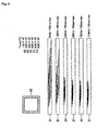
Figure 4 is an explanatory view showing the change in the heated region when the current frequency f was varied (the wall thickness of the steel tube was 3 mm, and the feed speed f was 100 mm/sec). -
Figure 5 is an explanatory view showing the results of numerical analysis for the case in which current with a current frequency of 25 kHz is supplied to a 2-winding induction heating coil and the feed speed V of a steel tube is varied. -
Figure 6 is an explanatory view showing the results of numerical analysis for the case in which the current frequency f of current supplied to a 2-winding induction heating coil is varied and a steel tube is fed with a feed speed V of 100 mm/sec. -
Figure 7 is a graph showing the relationship between the feed speed V, the current frequency f, and the heating width when using a 2-winding induction heating coil. -
Figure 8 is a graph showing the relationship between the feed speed V, the current frequency f, and the maximum possible current when using a 2-winding induction heating coil. -
Figure 9 is a graph showing the range for an appropriate feed speed V and an appropriate current frequency f when using a 2-winding induction heating coil. -
Figure 10 is an explanatory view schematically showing the structure of a manufacturing apparatus using an articulated robot. -
Figure 11 is an explanatory view showing an articulated robot. -
Figure 12 is an explanatory view schematically showing a manufacturing apparatus disclosed in Patent Document 1. -
- 0
- manufacturing apparatus
- 1
- metal material
- 1a
- high temperature portion
- 2
- support mechanism
- 3
- feed mechanism
- 4
- movable roller die
- 4a
- roll pair
- 5
- induction heating coil
- 6
- water cooling mechanism
- 10, 10-1
- manufacturing apparatus
- 11
- feed mechanism
- 12
- chuck
- 13
- support mechanism
- 14
- heating mechanism
- 14a
- induction heating coil
- 15
- gripping mechanism
- 16
- cooling mechanism
- 17
- body
- 18
- first base
- 19
- second base
- 20
- moving mechanism
- 22
- x axis tilt motor
- 23
- x axis shift motor
- 24
- y axis tilt motor
- 25
- y axis shift motor
- 26
- z axis tilt motor
- 27
- x axis shift motor
- 30
- model for numerical analysis
- 31
- steel tube
- 31 a
- high temperature portion
- 32, 32-1, 32-2
- induction heating coil
-
Figure 1 is an explanatory view schematically showing in simplified form the structure of an example of amanufacturing apparatus 10 according to the present invention. - As shown in this figure, the
manufacturing apparatus 10 has afeed mechanism 11, asupport mechanism 13, aheating mechanism 14, acooling mechanism 16, and agripping mechanism 15. These components will be explained in sequence. - The
feed mechanism 11 feeds a metal material 1 in its lengthwise direction. The metal material 1 is an elongated hollow member having a closed cross-sectional shape. In the following explanation, an example will be given of the case in which the metal material 1 is a steel tube. The present invention is not limited to the case in which the metal material is a steel tube 1. For example, a hollow metal material having a transverse cross-sectional shape of a rectangle, an ellipse, an oblong shape, a polygon, or a combination of a polygon and a circle, or a combination of a polygon and an ellipse can be used in the same manner as a steel tube 1. - An example of the
feed mechanism 11 is a feed mechanism using an electric servo cylinder. Thefeed mechanism 11 is not restricted to a specific type. Known feed mechanisms such as a feed mechanism using a ball screw or a feed mechanism using a timing belt or a chain can be used equally well as thefeed mechanism 11. - The steel tube 1 is movably supported by a
chuck 12 and is fed by thefeed mechanism 11 at a predetermined feed speed V (mm/sec) in its axial direction (lengthwise direction). Thechuck 12 supports the steel tube 1 in order to feed the steel tube 1. Thechuck 12 may be omitted. - The
support mechanism 13 movably supports the steel tube 1 which is being fed in its axial direction by thefeed mechanism 11 at a first position A. - An example of the
support mechanism 13 is a fixed guide. Thesupport mechanism 13 is not limited to a specific type of support mechanism. One or more pairs of opposing non-driven rolls may be used as thesupport mechanism 13. A known support mechanism can be used equally well as thesupport mechanism 13. - The steel tube 1 passes the installation position A of the
support mechanism 13 and is fed in its axial direction. Thesupport mechanism 13 may be replaced by thechuck 12. - The
heating mechanism 14 performs induction heating of the steel tube 1 being fed. Theheating mechanism 14 is disposed at a second position B located downstream of the first position A in the feed direction of the steel tube 1. - In the
manufacturing apparatus 10, when the wall thickness of the steel tube 1 is at most 2.0 mm, thefeed mechanism 11 feeds the steel tube 1 with a feed speed V of 5 - 150 mm/sec. Theheating mechanism 14 has aninduction heating coil 14a with 1 winding, and theinduction heating coil 14a is supplied with an alternating current having a current frequency of 5 - 100 kHz. - In the
manufacturing apparatus 10, when the wall thickness of the steel tube 1 is greater than 2.0 mm and at most 3.0 mm, theheating mechanism 14 has aninduction heating coil 14a with 2 windings. Thefeed mechanism 11 and theheating mechanism 14 adjust the feed speed V (mm/sec) of the steel tube 1 by thefeed mechanism 11 and the current frequency f (kHz) of the alternating current supplied to theinduction heating coil 14a so as to satisfy the relationships: - f < 3000/V and f ≤ 0.08 V
wherein 5 kHz ≤ f ≤ 100 kHz and 5 mm/sec ≤ V ≤ 150 mm/sec. - "An induction heating coil having 1 winding" is not limited to an induction heating coil in which the coil body completely surrounds the periphery of the steel tube 1. "An induction heating coil have 1 winding" includes an induction heating coil having a coil body which surrounds most of the steel tube 1 but does not surround a portion of the outer periphery of the steel tube 1. Specifically, an induction heating coil having a coil body which surrounds at least 70% of the outer periphery of the steel tube 1 falls within the scope of "an induction heating coil having 1 winding".
- The reason for defining the feed speed and current frequency as above will be explained while referring to the results of numerical analysis conducted by the present inventors.
-
Figure 2 is an explanatory view showing amodel 30 for numerical analysis. As shown inFigure 2 , thenumerical analysis model 30 has cylindrical two coordinates. - In this numerical analysis, the shape of the
high temperature portion 31a formed when the wall thickness of thesteel tube 31, the current frequency f of the current supplied to theinduction heating coil 32, and the feed speed V of thesteel tube 31 were varied was investigated by magnetic field analysis and heat transfer analysis. - Assuming that the
induction heating coil 32 was constituted by a copper tube having a square transverse cross-sectional shape measuring 15 mm on a side, numerical analysis was carried out under the following conditions: - diameter of steel tube 31: 38.1 mm
- distance d between the
induction heating coil 32 and the steel tube 31: 3 mm - current frequency f: 5, 10, 25, 50, 75, or 100 kHz (6 levels)
- wall thickness of steel tube 31: 1.0, 2.0, or 3.0 mm (3 levels)
- feed speed V of steel tube 31: 5, 10, 50, 75, 100, 125, or 150 mm/sec (7 levels).
- The position for the start of cooling of the
heated steel tube 31 was 10 mm downstream of the projectedposition 33 of the end of theinduction heating coil 32. -
Figure 3 shows the results of numerical analysis of the temperature distribution of thesteel tube 31 for the case in which the wall thickness of thesteel tube 31 was 3 mm and the current frequency f was 25 kHz.Figure 3 shows the dependence of the high temperature portion of thesteel tube 31 on the feed speed. InFigure 3 and below-describedFigures 4 - 6 , the line at the upper portion of thesteel tube 31 indicates the outer surface of thesteel tube 31 and the line at the lower portion of thesteel tube 31 indicates the inner surface of thesteel tube 31. - In general, the resistance to deformation of a steel material greatly decreases in a temperature range of 800° C and above. Therefore, in this numerical analysis, the heated region was made one in which the temperature increased to at least 800° C. All calculations were carried out under conditions such that the maximum temperature of the outer surface of the
steel tube 31 was 1000° C. - As shown in
Figure 3 , as the feed speed V increased from 5 to 10, 50, 75, 100, 125, and 150 mm/sec, the difference in temperature between the outer surface and the inner surface of the steel tube 1 increased. This is because the outer surface of thesteel tube 31 is directly heated by induction heating, while the inner surface of thesteel tube 31 is heated only by conduction from the outer surface. Therefore, the higher the feed speed V of thesteel tube 31, the smaller is the time for which the inner surface of thesteel tube 31 is heated. - As shown in
Figure 3 , when the feed speed V of thesteel tube 31 is 5 or 10 mm/sec, there is almost no temperature difference between the inner surface and the outer surface of thesteel tube 31, and bending can be carried out without any problems. When performing bending of a steel material, the uniformity of temperature in the plate thickness direction (the uniformity of the temperature distribution) is important, and particularly it is necessary to control the width of the region in which the temperature is at 800° C or above (referred to below as the effective heated width). - When the feed speed V of the
steel tube 31 becomes 50 mm/sec, the effective heated width (the region shown by A inFigure 3 ) becomes narrow. When the feed speed V of thesteel tube 31 reaches 75 mm, the effective heated width A becomes nearly 0. If the effective heated width A is 0, it becomes impossible to perform bending with good accuracy. When the feed speed V of thesteel tube 31 becomes 100 mm/sec or higher, the inner surface of thesteel tube 31 can no longer be heated to at least 800° C and it becomes impossible to carry out bending. - In this manner, the higher the feed speed V of the
steel tube 31 or the larger the wall thickness of thesteel tube 31, the more the effective heated width of thesteel tube 31 decreases, and it becomes more difficult to carry out bending. Based on the above results, the feed speed V of thesteel tube 31 is made at least 5 mm/sec to at most 150 mm/sec. - It is not easy to vary the current frequency f of an induction heating mechanism, so it is necessary to select a suitable current frequency f when designing the induction heating mechanism.
-
Figure 4 is an explanatory view showing the changes in the heated region when the current frequency f was varied (wall thickness ofsteel tube 31 = 3 mm, feed speed V = 100 mm/sec). - The lower the current frequency f, the deeper is the electromagnetic skin depth heated by induction heating. Therefore, when the feed speed V of the
steel tube 31 is constant, the lower the current frequency f, the more of the inner surface of thesteel tube 31 can be heated to 800° C or above. However, in the present invention, the lower the current frequency f, the larger is the effective heated width A by induction heating, so the dimensional accuracy of the bent member decreases. -
Figure 5 is an explanatory view showing the results of analysis when current with a current frequency f of 25 kHz was supplied to an induction heating coil having 2 windings 31-1 and 31-2 and the feed speed V of thesteel tube 31 was varied.Figure 6 is an explanatory view showing the results of analysis when the current frequency f of the current supplied to the induction heating coils having 2 windings 31-1 and 31-2 was varied and thesteel tube 31 was fed at a speed of 100 mm/sec. - From a comparison of the results shown in
Figures 5 and6 and the results shown inFigures 3 and4 , it can be seen that as the number of windings of the induction heating coil increases, the position of the start of heating of thesteel tube 31 moves towards the upstream side. Therefore, although the effective heated width A increases in the axial direction of thesteel tube 31, it is possible to perform heating up to the inner surface of thesteel tube 31. - As a result of carrying out a large number of analyses which varied the number of windings of the
induction heating coil 32, the current frequency f, and the feed speed V of thesteel tube 31 as shown inFigures 3 - 6 , the present inventors determined the relationship between the feed speed V, the current frequency f, and the wall thickness such that the effective heat width A does not become zero. Table 1 shows the relationship between the current frequency f, the feed speed V, and the wall thickness of a steel tube which can be bent when using an induction heating coil having 1 winding.
- The dash symbols (-) in Table 1 indicates that the effective heated width A is zero or higher with a wall thickness of at most 3 mm, namely, it indicates that a steel tube with a wall thickness of at most 3 mm can be subjected to bending. The numbers in Table 1 indicate the critical working thickness (mm); namely, the effective heat width A becomes zero when the wall thickness exceeds this value. Thus, if the maximum wall thickness of a
steel tube 31 for use withmanufacturing apparatus 0 is made 3 mm, the conditions in the region surrounded by the dashed line in Table 1 are the conditions under which bending is possible. - The
induction heating coil 32 is typically made of a copper alloy. The current which can be passed through theinduction heating coil 32 depends upon the cross-sectional area of theinduction heating coil 32 and the cooling method, but it is normally a maximum of 10,000 A. As shown in Table 1, in order to increase the feed speed V of thesteel tube 31, it is necessary to lower the current frequency f. If the current frequency f is lowered, the current in theinduction heating coil 32 increases. - Table 2 shows the current (A) which needs to be supplied to an
induction heating coil 32 having 1 winding in order to perform heating to 1000° C when asteel tube 31 has a wall thickness of 3 mm.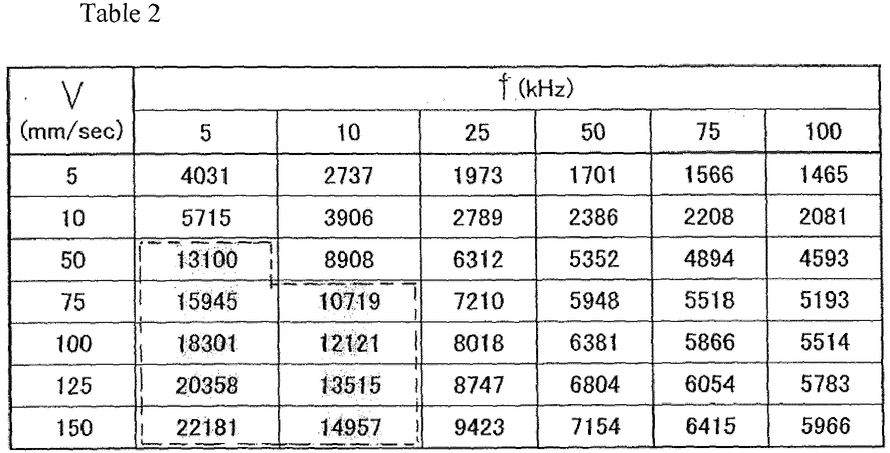
- As shown by the region surrounded by the dashed line in Table 2, when the current frequency f is low and the feed speed V of the
steel tube 31 is high, the current exceeds 10,000 A, so it is impossible from a practical standpoint to carry out induction heating. - As shown in Table 1, in order to make the feed speed V of the
steel tube 31 at least 100 mm/sec, it is necessary to make the current frequency f at most 10 kHz. However, with aninduction heating coil 32 having 1 winding, the current ends up exceeding 10,000 A. - In order to solve this problem, it is effective for the induction heating coil to have 2 windings. By increasing the number of windings from 1 to 2, it is possible to decrease the current per winding, but the heated width in the axial direction of the
steel tube 31 increases. - From Tables 1 and 2, it can be seen that when the induction heating coil has 1 winding, conditions in which the feed speed V is at most 150 mm/sec and the current frequency f is 25 - 75 kHz are suitable for heating a
steel tube 31 having a wall thickness of 2.0 mm. - Table 3 shows the results of numerical analysis of the current (A) necessary for heating a
steel tube 31 to 1000° C when the induction heating coil has 2 winding and the wall thickness of thesteel tube 31 is 3 mm.
- As shown in Table 3, when the induction heating coil has 2 windings, even if the current frequency f is 10 kHz, it is possible to carry out bending with a feed speed V of 100 mm/sec. The conditions in the region surrounded by the dashed line in Table 3 show the conditions for which the current exceeds 10,000 A and in which it is impossible from a practical standpoint to carry out induction heating.
- Table 4 shows the results of analysis of the region in which the effective heated width A is higher than zero when the induction heating coil has 2 windings. The symbols and numbers in Table 4 are the same as in Table 1.

- As shown by the region surrounded by the dashed line in Table 4, when the induction heating coil has 2 windings, the heated width is greater than with 1 winding, so the conditions in which the effective heated width A can be guaranteed are expanded.
-
Figure 5 shows the effective heated width A (mm) when the induction heating coil has one winding, andFigure 6 shows the effective heated width A (mm) when the induction heating coil has 2 windings.Table 5 V (mm/sec) f(kHz) 5 10 25 50 75 100 5 16.54 15.12 15.83 17.74 18.38 19.08 10 17.10 15.65 16.15 18.29 19.35 20.12 50 20.33 19.04 19.64 21.46 22.47 23.10 75 21.47 19.21 19.32 21.02 22.17 22.71 100 21.47 19.29 19.51 20.48 21.56 22.28 125 21.91 19.90 19.83 20.47 21.25 21.93 150 22.51 20.96 20.13 20.39 21.16 21.68 
- As shown in Table 5, the effective heated width A becomes at most 25 mm under all conditions with 1 winding, but as shown by the region surrounded by the dashed line in Table 6, when there are 2 windings, depending upon the conditions, the effective heated width A sometimes exceeds 30 mm.
- In order to guarantee the working accuracy of the
manufacturing apparatus 0, the effective heated width A is preferably as narrow as possible. The effective heated width A (mm) is preferably at most around 30 mm. When the wall thickness of thesteel tube 31 is at most 2.0 mm, using aninduction heating coil 32 having 1 winding can decrease the effective heated width A (mm), whereby the dimensional accuracy of a bent member can be guaranteed. From Table 1 and Table 2, it can be seen that in that situation, the feed speed V is preferably at most 150 mm/sec and the current frequency f is preferably from 25 kHz to 100 kHz. - When the wall thickness is greater than 2.0 mm and at most 3.0 mm, it is preferable to use an induction heating coil of 2 windings 32-1 and 32-2. In this case as well, it is preferable for the effective heated width A to be at most 30 mm in order to guarantee the dimensional accuracy of the bent member.
- The relationship shown in Table 6 is illustrated by a graph in
Figure 7 . The hollow circles in the graph ofFigure 7 show the case in which the effective heated width A is at most 30 mm, and the solid squares show the case when the effective heated width A exceeds 30 mm. - As shown by the graph in
Figure 7 , the effective width A can be made at most 30 mm if the current frequency f (kHz) and the feed speed V (mm) satisfy the relationship given by the approximate formula f < 3000V. - From the graph shown in
Figure 7 , it can be seen that a current frequency of at most 25 kHz is preferred when using an induction heating coil of 2 windings 32-1 and 32-2. However, when the current frequency f is low, it is necessary to take into consideration the current which can pass through the coil as shown in Table 3. - This relationship is shown by a graph in
Figure 8 . The hollow circles in the graph ofFigure 8 show a current value which can pass through the coil, and the solid squares show a current value which cannot pass through the coil. - From the graph of
Figure 8 , the region in which the current can pass through the coil when an induction heating coil of 2 windings 32-1 and 32-2 is used is the region given by the approximate formula f ≥ 0.08 V. -
Figure 9 is a graph showing the region inFigure 7 where the effective heated width A is at most around 30 mm in combination with the region inFigure 8 where the current can pass. In the graph ofFigure 9 , the region in which the effective heated width A cannot be guaranteed regardless of how the current frequency f and the feed speed V are adjusted is shown by portion LP marked with a lattice (f ≥ 25 kHz and V ≥ 125 mm/sec). - For the above-mentioned reasons, when the wall thickness of the steel tube 1 is at most 2.0 mm, the steel tube 1 is fed by the
feed mechanism 11 at a feed speed V of 5 - 150 mm/sec, and induction heating of the steel tube 1 is carried out using aninduction heating coil 14a having 1 winding as theheating mechanism 14 and by supplying theinduction heating coil 14a of 1 winding with an alternating current having a current frequency f of 5 - 100 kHz. - When the wall thickness of the steel tube 1 is greater than 2.0 mm and at most 3.0 mm, an
induction heating coil 14a having 2 windings is used as theheating mechanism 14, and thefeed mechanism 11 and theheating mechanism 14 are preferably adjusted so that the feed speed V (mm/sec) of the steel tube 1 by thefeed mechanism 11 and the current frequency f (kHz) of the alternating current supplied to theinduction heating coil 14a satisfy the relationships f < 3000/V and f ≥ 0.08 V, under theconditions 5 kHz ≤ f ≤ 100 kHz and 5 mm/sec ≤ V ≤ 150 mm/sec. - As stated above, when the steel tube 1 is heated using an
induction heating coil 14a with 2 windings, the heated width A of the steel tube 1 slightly increases, but such a heating coil can be applied even when the wall thickness of the steel tube 1 is at most 2.0 mm. - By varying the distance between the steel tube 1 and the
induction heating coil 14a in a direction which is parallel to the direction perpendicular to the axial direction of the steel tube 1, it is possible to non-uniformly heat at least a portion of the steel tube 1 in the circumferential direction. - Furthermore, by heating the steel tube 1 with at least one additional heating mechanism disposed on the upstream side of
heating mechanism 14, it is possible to heat the steel tube 1 two or more times or to non-uniformly heat a portion of the steel tube 1 in the circumferential direction. - The
cooling mechanism 16 is disposed at a third position C on the downstream side of the second position B in the feed direction of the steel tube 1. Thecooling mechanism 16 cools the heated steel tube 1. By cooling the steel tube 1 with thecooling mechanism 16, ahigh temperature portion 1a which moves in the axial direction of the steel tube 1 is locally formed. Thehigh temperature portion 1a has a resistance to deformation which is much lower than that of other portions. - The
cooling mechanism 16 can be any mechanism which can cool the steel tube 1 at a desired cooling speed, and it is not limited to a specific type of cooling mechanism. In general, an example of the cooling mechanism is a water cooling mechanism which cools the steel tube 1 by spraying cooling water at a predetermined position on the outer peripheral surface of the steel tube 1. - As shown in
Figure 1 , cooling water is sprayed so as to be sloped toward the feed direction of the steel tube 1. By varying the distance of thecooling mechanism 16 with respect to the steel tube 1 in a direction which is parallel to the direction perpendicular to the axial direction of the steel tube 1, the length of thehigh temperature portion 1a in the axial direction can be adjusted. - The gripping
mechanism 15 is disposed in a region D downstream of the third position C in the feed direction of the steel tube 1. The grippingmechanism 15 moves three-dimensionally in a direction including at least the feed direction of the steel tube 1 within a workspace including a space on the upstream side of the third position C in the feed direction of the steel tube 1. As a result, the grippingmechanism 15 imparts a bending moment to thehigh temperature portion 1a formed in the steel tube 1. In general a chuck mechanism is used as the grippingmechanism 15. - In the present invention, the gripping
mechanism 15 which can move three-dimensionally can of course move two-dimensionally. By moving thegripping mechanism 15 two-dimensionally, it is possible to carry out bending in which the bending direction varies two-dimensionally and to manufacture a bent member having a bending direction which varies two-dimensionally such as is the case with S-shaped bending. - The workspace means a three-dimensional space defined by Equations (3), (4), and (5).


- In Equations (3) - (5), D means the smallest outer dimension (mm) of the bent member, Rmin means the smallest radius of curvature (mm) of the bent member, and x, y, and θ are cylindrical coordinates having the second position as an origin, wherein a positive value for x is in the instantaneous feed direction of the bent member, y is in the direction perpendicular to x in a horizontal plane, and θ is the angle in the circumferential direction.
- The gripping
mechanism 15 bends the steel tube 1 by moving three-dimensionally within the workspace, whereby a bent member having bent portions intermittently or continuously in its lengthwise direction is manufactured. - The workspace is a subjective space, so objects such as various mechanisms can be present in the workspace.
- The gripping
mechanism 15 includes abody 17 with a pillar-like outer shape and a movingmechanism 20. - The
body 17 is constituted by a hollow member. The hollow member has an inner peripheral surface having a shape fitting the outer peripheral surface of the steel tube 1. Thebody 17 grips the steel tube 1 by contacting the outer surface of the end of the steel tube 1. - In contrast to the example shown in
Figure 1 , thebody 17 may be constituted by a tubular member having an outer peripheral surface with a shape fitting the inner peripheral surface of the steel tube 1. In this case, thebody 17 grips the steel tube 1 by being inserted into the end of the steel tube 1. - The moving
mechanism 20 is constituted by a first base 18 and a second base 19. Thebody 17 is mounted on the first base 18, and the first base 18 can move in a direction perpendicular to the feed direction of the steel tube at the first position A (in the vertical direction inFigure 1 ). The second base 19 is disposed so as to be able to move the first base 18 in the feed direction. - Movement of the first base 18 and the second base 19 is individually carried out by a ball screw and a drive motor. The
body 17 can be moved two-dimensionally in a horizontal plane by the movingmechanism 20.Reference number 22 inFigure 1 indicates an x axis tilt motor,reference number 23 indicates an x axis shift motor,reference number 24 indicates a y axis tilt motor,reference number 25 indicates a y axis shift motor,reference number 26 indicates a z axis tilt motor, andreference number 27 indicates an x axis shift motor. - Instead of the moving
mechanism 20 shown inFigure 1 , thebody 17 may be supported by an articulated robot having joints which can rotate around at least one axis. -
Figure 10 is an explanatory view schematically showing the structure of a manufacturing apparatus 10-1 using an articulatedrobot 21, andFigure 11 is an explanatory view showing the articulatedrobot 21. - The articulated
robot 21 can easily support thebody 17 so as to be able to move three-dimensionally in a direction including at least the feed direction of the steel tube 1. - Next, the state when manufacturing a bent member by this
manufacturing apparatus 10 will be explained. - First, an elongated steel tube 1 is supported at the first position A by the
support mechanism 13 and is fed in its lengthwise direction by thefeed mechanism 11. - Next, when the wall thickness of the steel tube 1 is at most 2.0 mm, the
feed mechanism 11 feeds the steel tube 1 with a feed speed V of 5 - 150 mm/sec, and by supplying an alternating current with a current frequency V of 5 - 100 kHz to theinduction heating coil 14a of 1 winding which constitutes theheating mechanism 14 disposed at the second position B, the steel tube is subjected to induction heating. - When the wall thickness of the steel tube 1 is greater than 2.0 mm and at most 3.0 mm, the steel tube 1 undergoes induction heating by controlling the feed speed V (mm/sec) of the steel tube 1 by the
feed mechanism 11 and the current frequency f (kHz) of the alternating current supplied to theinduction heating coil 14a of 2 winding which constitutes theheating mechanism 14 so as to satisfy the relationships f < 3000/V and f ≥ 0.08 V. - Next, a
high temperature portion 1a is formed in the steel tube 1 by cooling the steel tube 1 by thecooling mechanism 16 at the third position C. - Then, in region D, the position of the
gripping mechanism 15 which grips the steel tube 1 is varied three-dimensionally in a direction including at least the feed direction of the steel tube 1 within the workspace to impart a bending moment to thehigh temperature portion 1a of the steel tube 1. - These processes are carried out over the entire length of the steel tube 1 in accordance with the target shape of the bent member. As a result, a bent member having a bent portion which is three-dimensionally bent intermittently or continuously in the lengthwise direction is continuously manufactured.
- By locally heating the steel tube 1 at the second position B to a temperature range in which quench hardening is possible (to at least the Ac3 point) and rapidly cooling it at a predetermined cooling speed at the third position C, it is possible to harden at least a portion of the steel tube 1. As a result, a bent member intermittently or continuously having a hardened portion at least in the lengthwise direction and/or in the circumferential direction in a cross section crossing the lengthwise direction is manufactured.
- A bent member can be continuously manufactured by disposing the
manufacturing apparatus 10 on the exit side of a manufacturing apparatus for seam welded steel tube. Specifically, a continuous manufacturing apparatus may comprise an uncoiler for continuously paying out a steel strip, a forming apparatus for forming the paid out steel strip into a tube having a predetermined cross-sectional shape, a welding apparatus for welding the abutting side edges of the steel strip to form a continuous tube, a post-treatment apparatus which cuts off the weld bead and if necessary performs post-annealing or sizing, and amanufacturing apparatus 10 disposed on the exit side of the post-treatment apparatus. - A bent member can also be continuously manufactured using a continuous manufacturing apparatus comprising a roll forming line constituted by an uncoiler for continuously paying out a steel strip and a forming apparatus for forming the paid-out steel strip into a desired cross-sectional shape, and a
manufacturing apparatus 10 disposed on the exit side of the forming apparatus. - The
manufacturing apparatus 10 can stably form ahigh temperature portion 1a which is uniform in the circumferential direction of a steel tube 1 in a narrow region in the axial direction of the steel tube 1. As a result, it can efficiently and inexpensively manufacture a bent member having a high strength and excellent shape retention, having a predetermined hardness distribution and a desired dimensional accuracy, and having at least two portions in the lengthwise direction with different radii of curvature from each other instead of a constant radius of curvature in the lengthwise direction. - The manufacturing apparatus 10-1 grips a steel tube 1 with a
gripping mechanism 15 which is supported by an articulated robot or the like and carries out bending of a steel tube 1. Therefore, a bent portion can be provided with a large bending angle, the surface can keep good condition because surface flaws can be suppressed, dimensional accuracy can be guaranteed, and a bent member can be manufactured with excellent operating efficiency.
Claims (8)
- A method of manufacturing a bent member having a bent portion which is bent three-dimensionally intermittently or continuously in its lengthwise direction comprising
supporting a hollow elongated metal material having a closed transverse cross-sectional shape at a first position while feeding it in its lengthwise direction,
forming a high temperature portion which moves in the axial direction of the metal material by performing induction heating of the metal material at a second position located downstream of the first position in the feed direction of the metal material using an induction heating coil and cooling the metal material at a third position located downstream of the second position in the feed direction of the metal material, and
three-dimensionally varying the position of a gripping mechanism which grips the metal material in a region downstream of the third position in the feed direction of the metal material to apply a bending moment to the high temperature portion,
characterized in that
when the wall thickness of the metal material is at most 2.0 mm, the feed speed of the metal material is made 5 - 150 mm/sec, an induction heating coil having 1 winding is used as the induction heating coil, and an alternating current at 5 - 100 kHz is applied to the induction heating coil, and/or
when the wall thickness of the metal material is greater than 2.0 mm and at most 3.0 mm, an induction heating coil having 2 windings is used as the induction heating coil, and the frequency (kHz) of the alternating current supplied to the induction heating coil and the feed speed (mm/sec) of the metal material are adjusted so as to satisfy the relationships given by the following Equations (1) and (2):

wherein, f is the frequency, V is the feed speed, 5 kHz ≤ f ≤ 100 kHz, and 5 mm/sec ≤ V ≤ 150 mm/sec. - A method of manufacturing a bent member as set forth in claim 1 wherein the bent member has at least two portions in its lengthwise direction which are different in bending radius from each other.
- A method of manufacturing a bent member as set forth in claim 1 or claim 2 wherein the metal material has a transverse cross-sectional shape which is circular, rectangular, elliptical, oblong, polygonal, a combination of a polygon and a circle, or a combination of a polygon and an ellipse.
- A method of manufacturing a bent member as set forth in any one of claims 1 - 3 wherein the gripping mechanism grips the metal material by being inserted into an end of the metal material.
- A method of manufacturing a bent member as set forth in any one of claims 1 - 3 wherein the gripping mechanism grips the metal material by contacting the outer surface of an end of the metal material.
- A method of manufacturing a bent member as set forth in any one of claims 1 - 5 wherein the metal material is hardened in at least a portion of its lengthwise direction by being locally heated at the second position to a temperature at which quench hardening is possible and being cooled at the third position.
- A method of manufacturing a bent member as set forth in any one of claims 1 - 6 wherein the bent member intermittently or continuously has a hardened portion in its lengthwise direction and/or in the circumferential direction in a cross section which crosses the lengthwise direction.
- A manufacturing apparatus for a bent member comprising
a feed mechanism for feeding an elongated hollow metal material having a closed transverse cross-sectional shape in its lengthwise direction,
a support mechanism for supporting the metal material being fed at a first position,
a heating mechanism for induction heating of the metal material being fed at a second position located downstream of the first position in the feed direction of the metal material,
a cooling mechanism for cooling the heated portion of the metal material at a third position located downstream of the second position in the feed direction of the metal material to locally form in the metal material a high temperature portion which moves in the axial direction of the metal material, and
a gripping mechanism which moves three-dimensionally while gripping the metal material being fed in a region downstream of the third position in the feed direction of the metal material to apply a bending moment to the high temperature portion,
characterized in that
when the wall thickness of the metal material is at most 2.0 mm, the feed mechanism feeds the metal material at 5 - 150 mm/sec, the heating mechanism has an induction heating coil with 1 winding, and the induction heating coil is supplied with an alternating current at 5 - 100 kHz, and/or
when the wall thickness of the metal material is greater than 2.0 mm and at most 3.0 mm, the heating mechanism has an induction heating coil with 2 windings, and the feed mechanism and the heating mechanism adjust the feed speed (mm/sec) of the metal material by the feed mechanism and the frequency (kHz) of the alternating current supplied to the induction heating coil so as to satisfy the relationships give by the following Equation (1) and Equation (2):

wherein f is the frequency, V is the feed speed, 5 kHz ≤ f ≤ 100 kHz, and 5 mm/sec ≤ V ≤ 150 mm/sec.
Applications Claiming Priority (2)
| Application Number | Priority Date | Filing Date | Title |
|---|---|---|---|
| JP2010001383 | 2010-01-06 | ||
| PCT/JP2011/050091 WO2011083816A1 (en) | 2010-01-06 | 2011-01-06 | Flexure member manufacturing method and flexture member manufacturing device |
Publications (3)
| Publication Number | Publication Date |
|---|---|
| EP2522442A1 true EP2522442A1 (en) | 2012-11-14 |
| EP2522442A4 EP2522442A4 (en) | 2018-03-21 |
| EP2522442B1 EP2522442B1 (en) | 2020-10-28 |
Family
ID=44305553
Family Applications (1)
| Application Number | Title | Priority Date | Filing Date |
|---|---|---|---|
| EP11731814.7A Active EP2522442B1 (en) | 2010-01-06 | 2011-01-06 | Flexure member manufacturing method and flexture member manufacturing device |
Country Status (12)
| Country | Link |
|---|---|
| US (1) | US8567225B2 (en) |
| EP (1) | EP2522442B1 (en) |
| JP (1) | JP5472324B2 (en) |
| KR (1) | KR101414346B1 (en) |
| CN (1) | CN102791395B (en) |
| AU (1) | AU2011204164B2 (en) |
| BR (1) | BR112012016810A8 (en) |
| CA (1) | CA2786458C (en) |
| EA (1) | EA020748B1 (en) |
| MX (1) | MX2012007910A (en) |
| WO (1) | WO2011083816A1 (en) |
| ZA (1) | ZA201205733B (en) |
Cited By (1)
| Publication number | Priority date | Publication date | Assignee | Title |
|---|---|---|---|---|
| EP2900036A4 (en) * | 2012-09-21 | 2016-06-01 | Nippon Steel & Sumitomo Metal Corp | HIGH FREQUENCY INDUCTION HEATING DEVICE AND PROCESSING DEVICE |
Families Citing this family (19)
| Publication number | Priority date | Publication date | Assignee | Title |
|---|---|---|---|---|
| BR112012000950B1 (en) | 2009-07-14 | 2020-01-07 | Sumitomo Pipe & Tube Co., Ltd. | METHOD AND APPARATUS FOR MAKING A CURVED MEMBER |
| DE102013001898A1 (en) * | 2013-02-05 | 2014-08-07 | Thermprotec Gmbh | Method for improving the temperature distribution in the inductive or conductive hardening of shaped pipes and rods, in particular but not exclusively for use as suspension stabilizers in automobiles |
| CN103706691B (en) * | 2013-12-29 | 2015-08-19 | 哈尔滨工业大学 | Electronic universal tester is utilized to carry out sheet metal bending forming method |
| WO2015144103A1 (en) * | 2014-03-25 | 2015-10-01 | Technische Universität Dortmund | Method and apparatus for the incremental production of bent wires, tubes, profiles or similar from rod-like metallic materials |
| DE112015004072T5 (en) | 2014-09-04 | 2017-05-11 | Temper Ip, Llc | Forming process with magnetic fields |
| AT516371B1 (en) * | 2014-12-02 | 2016-05-15 | Stonawski Rudolf | Device for bending a profile workpiece |
| US9955802B2 (en) | 2015-04-08 | 2018-05-01 | Fasteners For Retail, Inc. | Divider with selectively securable track assembly |
| DE102015106570B4 (en) * | 2015-04-28 | 2016-12-15 | AWS Schäfer Technologie GmbH | Method for induction bending forming of a pressure-resistant pipe with a large wall thickness and a large diameter |
| CN105170739B (en) * | 2015-08-10 | 2017-03-08 | 石家庄国祥运输设备有限公司 | The continuous elbow processing device of three dimensions |
| WO2017061445A1 (en) * | 2015-10-05 | 2017-04-13 | 新日鐵住金株式会社 | Method and device for manufacturing hardened steel, steel for hardening, and hardened steel |
| ES2663508B1 (en) * | 2017-03-31 | 2019-02-25 | La Farga Yourcoppersolutions S A | System and procedure to control the recrystallization of a metal tubular piece |
| JP6992680B2 (en) * | 2018-06-04 | 2022-01-13 | 日本製鉄株式会社 | 3D hot bending quenching device and quenching method |
| CN109834780A (en) * | 2019-04-01 | 2019-06-04 | 钛马迪家居江苏有限公司 | A kind of furniture element bender of achievable step-less adjustment |
| CN112387817B (en) * | 2020-10-27 | 2024-12-13 | 江苏正基电梯部件有限公司 | An escalator inner and outer cover arc forming device that is easy to maintain |
| JP7673410B2 (en) | 2021-01-13 | 2025-05-09 | トヨタ自動車株式会社 | Molding method |
| CN113441580B (en) * | 2021-08-31 | 2021-11-16 | 南通驰连机械有限公司 | Intelligent automatic numerical control pipe bending machine |
| DE102021127807A1 (en) | 2021-10-26 | 2023-04-27 | Bayerische Motoren Werke Aktiengesellschaft | Process for the area-wise forming of slender workpieces, workpiece and device |
| CN115971303A (en) * | 2022-12-26 | 2023-04-18 | 安徽远信重工有限公司 | An elbow pushing machine and its control method |
| CN118681968B (en) * | 2024-07-02 | 2025-09-30 | 南京航空航天大学 | A three-dimensional free-form forming device and method based on induction heating and quenching |
Family Cites Families (25)
| Publication number | Priority date | Publication date | Assignee | Title |
|---|---|---|---|---|
| US1891338A (en) * | 1931-02-09 | 1932-12-20 | Lester W Snell | Method of and means for bending tubes |
| JPS5938048B2 (en) * | 1975-09-18 | 1984-09-13 | 第一高周波工業 (株) | Continuous bending method and device for long materials |
| DE2555326C3 (en) * | 1975-12-05 | 1978-10-19 | Mannesmann Ag, 4000 Duesseldorf | Device for bending large pipes |
| NL165667C (en) * | 1976-09-03 | 1981-05-15 | Cojafex | METHOD AND APPARATUS FOR CONTINUOUSLY BENDING OF LONG-LIKE OBJECTS SUCH AS TUBES. |
| JPS5561326A (en) * | 1978-10-30 | 1980-05-09 | Dai Ichi High Frequency Co Ltd | Bending method for austenitic stainless cast steel pipe by high frequency induction heating |
| JPS6076232A (en) * | 1983-10-03 | 1985-04-30 | Toyota Motor Corp | Manufacture of high strength hollow stabilizer |
| DE3427639A1 (en) * | 1984-07-26 | 1986-02-06 | Cojafex B.V., Rotterdam | METHOD AND DEVICE FOR BENDING LONG-TERM WORKPIECES, IN PARTICULAR PIPES |
| JP3195082B2 (en) * | 1992-12-17 | 2001-08-06 | マツダ株式会社 | Metal member bending machine |
| JPH10314852A (en) * | 1997-05-14 | 1998-12-02 | Honda Motor Co Ltd | Terminal gripping device for work in tension bending machine |
| JP3814420B2 (en) * | 1998-09-25 | 2006-08-30 | 第一高周波工業株式会社 | Metal tube bending machine |
| US7024897B2 (en) * | 1999-09-24 | 2006-04-11 | Hot Metal Gas Forming Intellectual Property, Inc. | Method of forming a tubular blank into a structural component and die therefor |
| CA2320563C (en) * | 1999-09-24 | 2008-02-19 | Honda Giken Kogyo Kabushiki Kaisha | Method of generating control data for bending and torsion apparatuses |
| JP3400767B2 (en) * | 2000-02-28 | 2003-04-28 | 徹 佐藤 | Steel pipe bending apparatus and method |
| JP2001355047A (en) * | 2000-06-14 | 2001-12-25 | Kawasaki Steel Corp | High carbon steel pipe excellent in cold workability and induction hardening and method for producing the same |
| JP2002187730A (en) * | 2000-12-21 | 2002-07-05 | Matsushita Electric Ind Co Ltd | Pipe bending method and pipe bending apparatus |
| FR2845397B1 (en) * | 2002-10-02 | 2005-07-29 | Allevard Rejna Autosuspensions | INDUCTION TEMPERATURE INSTALLATION, IN PARTICULAR FOR THE MANUFACTURE OF SUSPENSION ELEMENTS |
| WO2005058625A1 (en) * | 2003-12-17 | 2005-06-30 | Sumitomo Metal Industries Ltd. | Metal tube for reinforcing vehicle body and member for reinforcing vehicle body using the same |
| ITRM20050048A1 (en) * | 2005-02-04 | 2006-08-05 | Cml Int Spa | BENDING MACHINE WITH A REDUCED BEND BENDING ARM. |
| JP4934283B2 (en) * | 2005-03-02 | 2012-05-16 | 住友金属工業株式会社 | Body reinforcement members |
| EP1857195B8 (en) * | 2005-03-03 | 2014-07-30 | Nippon Steel & Sumitomo Metal Corporation | Method for bending metal material and bent product |
| CN101678425A (en) * | 2007-04-04 | 2010-03-24 | 住友金属工业株式会社 | Method and apparatus for manufacturing bent product, and continuous manufacturing apparatus |
| JP5288749B2 (en) * | 2007-08-28 | 2013-09-11 | 第一高周波工業株式会社 | Metal tube bending apparatus and method |
| CN100464888C (en) * | 2007-12-26 | 2009-03-04 | 连式雄 | A process and device for pushing elbows by medium frequency induction heating |
| JP2009233731A (en) * | 2008-03-28 | 2009-10-15 | Tokyo Metropolitan Univ | Apparatus for and method of refining crystalline grain of metal pipe |
| JP2009291820A (en) * | 2008-06-06 | 2009-12-17 | Mazda Motor Corp | Hot bending method of metal tube, and its apparatus |
-
2011
- 2011-01-06 EP EP11731814.7A patent/EP2522442B1/en active Active
- 2011-01-06 MX MX2012007910A patent/MX2012007910A/en active IP Right Grant
- 2011-01-06 CA CA2786458A patent/CA2786458C/en not_active Expired - Fee Related
- 2011-01-06 JP JP2011549017A patent/JP5472324B2/en active Active
- 2011-01-06 AU AU2011204164A patent/AU2011204164B2/en not_active Ceased
- 2011-01-06 WO PCT/JP2011/050091 patent/WO2011083816A1/en not_active Ceased
- 2011-01-06 BR BR112012016810A patent/BR112012016810A8/en not_active Application Discontinuation
- 2011-01-06 KR KR1020127019764A patent/KR101414346B1/en not_active Expired - Fee Related
- 2011-01-06 CN CN201180012759.6A patent/CN102791395B/en active Active
- 2011-01-06 EA EA201290609A patent/EA020748B1/en not_active IP Right Cessation
-
2012
- 2012-07-06 US US13/542,840 patent/US8567225B2/en active Active
- 2012-07-30 ZA ZA2012/05733A patent/ZA201205733B/en unknown
Non-Patent Citations (1)
| Title |
|---|
| See references of WO2011083816A1 * |
Cited By (1)
| Publication number | Priority date | Publication date | Assignee | Title |
|---|---|---|---|---|
| EP2900036A4 (en) * | 2012-09-21 | 2016-06-01 | Nippon Steel & Sumitomo Metal Corp | HIGH FREQUENCY INDUCTION HEATING DEVICE AND PROCESSING DEVICE |
Also Published As
| Publication number | Publication date |
|---|---|
| WO2011083816A1 (en) | 2011-07-14 |
| KR20120099143A (en) | 2012-09-06 |
| MX2012007910A (en) | 2012-12-17 |
| EA020748B1 (en) | 2015-01-30 |
| CA2786458C (en) | 2014-09-23 |
| EA201290609A1 (en) | 2013-01-30 |
| CN102791395A (en) | 2012-11-21 |
| CA2786458A1 (en) | 2011-07-14 |
| AU2011204164B2 (en) | 2014-01-30 |
| JP5472324B2 (en) | 2014-04-16 |
| AU2011204164A1 (en) | 2012-08-02 |
| US8567225B2 (en) | 2013-10-29 |
| BR112012016810A2 (en) | 2016-04-19 |
| CN102791395B (en) | 2015-04-22 |
| BR112012016810A8 (en) | 2017-10-03 |
| EP2522442B1 (en) | 2020-10-28 |
| JPWO2011083816A1 (en) | 2013-05-13 |
| EP2522442A4 (en) | 2018-03-21 |
| US20130000375A1 (en) | 2013-01-03 |
| ZA201205733B (en) | 2013-04-24 |
| KR101414346B1 (en) | 2014-07-02 |
Similar Documents
| Publication | Publication Date | Title |
|---|---|---|
| EP2522442B1 (en) | Flexure member manufacturing method and flexture member manufacturing device | |
| US10406581B2 (en) | Method for manufacturing a worked member using an induction heating coil | |
| EP2368650B1 (en) | Method and device for manufacturing bent product | |
| AU2008235842B2 (en) | Method of manufacturing a bent product and an apparatus and a continuous line for manufacturing the same | |
| WO2025215859A1 (en) | Method for producing hollow bent component and device for producing hollow bent component |
Legal Events
| Date | Code | Title | Description |
|---|---|---|---|
| PUAI | Public reference made under article 153(3) epc to a published international application that has entered the european phase |
Free format text: ORIGINAL CODE: 0009012 |
|
| 17P | Request for examination filed |
Effective date: 20120802 |
|
| AK | Designated contracting states |
Kind code of ref document: A1 Designated state(s): AL AT BE BG CH CY CZ DE DK EE ES FI FR GB GR HR HU IE IS IT LI LT LU LV MC MK MT NL NO PL PT RO RS SE SI SK SM TR |
|
| RAP1 | Party data changed (applicant data changed or rights of an application transferred) |
Owner name: NIPPON STEEL & SUMITOMO METAL CORPORATION |
|
| DAX | Request for extension of the european patent (deleted) | ||
| RIC1 | Information provided on ipc code assigned before grant |
Ipc: B21D 7/16 20060101AFI20170922BHEP Ipc: C21D 9/08 20060101ALI20170922BHEP Ipc: B21D 7/12 20060101ALI20170922BHEP Ipc: C21D 1/42 20060101ALI20170922BHEP |
|
| RA4 | Supplementary search report drawn up and despatched (corrected) |
Effective date: 20180215 |
|
| RIC1 | Information provided on ipc code assigned before grant |
Ipc: B21D 7/16 20060101AFI20180210BHEP Ipc: B21D 7/12 20060101ALI20180210BHEP Ipc: C21D 9/08 20060101ALI20180210BHEP Ipc: C21D 1/42 20060101ALI20180210BHEP |
|
| STAA | Information on the status of an ep patent application or granted ep patent |
Free format text: STATUS: EXAMINATION IS IN PROGRESS |
|
| 17Q | First examination report despatched |
Effective date: 20190228 |
|
| RAP1 | Party data changed (applicant data changed or rights of an application transferred) |
Owner name: NIPPON STEEL CORPORATION |
|
| GRAP | Despatch of communication of intention to grant a patent |
Free format text: ORIGINAL CODE: EPIDOSNIGR1 |
|
| STAA | Information on the status of an ep patent application or granted ep patent |
Free format text: STATUS: GRANT OF PATENT IS INTENDED |
|
| RIC1 | Information provided on ipc code assigned before grant |
Ipc: B21D 7/16 20060101AFI20200617BHEP Ipc: C21D 9/60 20060101ALI20200617BHEP Ipc: C21D 11/00 20060101ALI20200617BHEP Ipc: C21D 1/42 20060101ALI20200617BHEP Ipc: C21D 9/08 20060101ALI20200617BHEP Ipc: B21D 7/12 20060101ALI20200617BHEP |
|
| INTG | Intention to grant announced |
Effective date: 20200721 |
|
| GRAS | Grant fee paid |
Free format text: ORIGINAL CODE: EPIDOSNIGR3 |
|
| GRAA | (expected) grant |
Free format text: ORIGINAL CODE: 0009210 |
|
| STAA | Information on the status of an ep patent application or granted ep patent |
Free format text: STATUS: THE PATENT HAS BEEN GRANTED |
|
| AK | Designated contracting states |
Kind code of ref document: B1 Designated state(s): AL AT BE BG CH CY CZ DE DK EE ES FI FR GB GR HR HU IE IS IT LI LT LU LV MC MK MT NL NO PL PT RO RS SE SI SK SM TR |
|
| REG | Reference to a national code |
Ref country code: GB Ref legal event code: FG4D |
|
| REG | Reference to a national code |
Ref country code: CH Ref legal event code: EP |
|
| REG | Reference to a national code |
Ref country code: AT Ref legal event code: REF Ref document number: 1327691 Country of ref document: AT Kind code of ref document: T Effective date: 20201115 |
|
| REG | Reference to a national code |
Ref country code: DE Ref legal event code: R096 Ref document number: 602011069086 Country of ref document: DE |
|
| REG | Reference to a national code |
Ref country code: IE Ref legal event code: FG4D |
|
| REG | Reference to a national code |
Ref country code: AT Ref legal event code: MK05 Ref document number: 1327691 Country of ref document: AT Kind code of ref document: T Effective date: 20201028 |
|
| REG | Reference to a national code |
Ref country code: NL Ref legal event code: MP Effective date: 20201028 |
|
| PG25 | Lapsed in a contracting state [announced via postgrant information from national office to epo] |
Ref country code: GR Free format text: LAPSE BECAUSE OF FAILURE TO SUBMIT A TRANSLATION OF THE DESCRIPTION OR TO PAY THE FEE WITHIN THE PRESCRIBED TIME-LIMIT Effective date: 20210129 Ref country code: RS Free format text: LAPSE BECAUSE OF FAILURE TO SUBMIT A TRANSLATION OF THE DESCRIPTION OR TO PAY THE FEE WITHIN THE PRESCRIBED TIME-LIMIT Effective date: 20201028 Ref country code: FI Free format text: LAPSE BECAUSE OF FAILURE TO SUBMIT A TRANSLATION OF THE DESCRIPTION OR TO PAY THE FEE WITHIN THE PRESCRIBED TIME-LIMIT Effective date: 20201028 Ref country code: NL Free format text: LAPSE BECAUSE OF FAILURE TO SUBMIT A TRANSLATION OF THE DESCRIPTION OR TO PAY THE FEE WITHIN THE PRESCRIBED TIME-LIMIT Effective date: 20201028 Ref country code: PT Free format text: LAPSE BECAUSE OF FAILURE TO SUBMIT A TRANSLATION OF THE DESCRIPTION OR TO PAY THE FEE WITHIN THE PRESCRIBED TIME-LIMIT Effective date: 20210301 Ref country code: NO Free format text: LAPSE BECAUSE OF FAILURE TO SUBMIT A TRANSLATION OF THE DESCRIPTION OR TO PAY THE FEE WITHIN THE PRESCRIBED TIME-LIMIT Effective date: 20210128 |
|
| REG | Reference to a national code |
Ref country code: LT Ref legal event code: MG4D |
|
| PG25 | Lapsed in a contracting state [announced via postgrant information from national office to epo] |
Ref country code: LV Free format text: LAPSE BECAUSE OF FAILURE TO SUBMIT A TRANSLATION OF THE DESCRIPTION OR TO PAY THE FEE WITHIN THE PRESCRIBED TIME-LIMIT Effective date: 20201028 Ref country code: PL Free format text: LAPSE BECAUSE OF FAILURE TO SUBMIT A TRANSLATION OF THE DESCRIPTION OR TO PAY THE FEE WITHIN THE PRESCRIBED TIME-LIMIT Effective date: 20201028 Ref country code: SE Free format text: LAPSE BECAUSE OF FAILURE TO SUBMIT A TRANSLATION OF THE DESCRIPTION OR TO PAY THE FEE WITHIN THE PRESCRIBED TIME-LIMIT Effective date: 20201028 Ref country code: BG Free format text: LAPSE BECAUSE OF FAILURE TO SUBMIT A TRANSLATION OF THE DESCRIPTION OR TO PAY THE FEE WITHIN THE PRESCRIBED TIME-LIMIT Effective date: 20210128 Ref country code: AT Free format text: LAPSE BECAUSE OF FAILURE TO SUBMIT A TRANSLATION OF THE DESCRIPTION OR TO PAY THE FEE WITHIN THE PRESCRIBED TIME-LIMIT Effective date: 20201028 Ref country code: ES Free format text: LAPSE BECAUSE OF FAILURE TO SUBMIT A TRANSLATION OF THE DESCRIPTION OR TO PAY THE FEE WITHIN THE PRESCRIBED TIME-LIMIT Effective date: 20201028 Ref country code: IS Free format text: LAPSE BECAUSE OF FAILURE TO SUBMIT A TRANSLATION OF THE DESCRIPTION OR TO PAY THE FEE WITHIN THE PRESCRIBED TIME-LIMIT Effective date: 20210228 |
|
| PG25 | Lapsed in a contracting state [announced via postgrant information from national office to epo] |
Ref country code: HR Free format text: LAPSE BECAUSE OF FAILURE TO SUBMIT A TRANSLATION OF THE DESCRIPTION OR TO PAY THE FEE WITHIN THE PRESCRIBED TIME-LIMIT Effective date: 20201028 |
|
| REG | Reference to a national code |
Ref country code: DE Ref legal event code: R097 Ref document number: 602011069086 Country of ref document: DE |
|
| PG25 | Lapsed in a contracting state [announced via postgrant information from national office to epo] |
Ref country code: RO Free format text: LAPSE BECAUSE OF FAILURE TO SUBMIT A TRANSLATION OF THE DESCRIPTION OR TO PAY THE FEE WITHIN THE PRESCRIBED TIME-LIMIT Effective date: 20201028 Ref country code: SK Free format text: LAPSE BECAUSE OF FAILURE TO SUBMIT A TRANSLATION OF THE DESCRIPTION OR TO PAY THE FEE WITHIN THE PRESCRIBED TIME-LIMIT Effective date: 20201028 Ref country code: LT Free format text: LAPSE BECAUSE OF FAILURE TO SUBMIT A TRANSLATION OF THE DESCRIPTION OR TO PAY THE FEE WITHIN THE PRESCRIBED TIME-LIMIT Effective date: 20201028 Ref country code: CZ Free format text: LAPSE BECAUSE OF FAILURE TO SUBMIT A TRANSLATION OF THE DESCRIPTION OR TO PAY THE FEE WITHIN THE PRESCRIBED TIME-LIMIT Effective date: 20201028 Ref country code: EE Free format text: LAPSE BECAUSE OF FAILURE TO SUBMIT A TRANSLATION OF THE DESCRIPTION OR TO PAY THE FEE WITHIN THE PRESCRIBED TIME-LIMIT Effective date: 20201028 Ref country code: SM Free format text: LAPSE BECAUSE OF FAILURE TO SUBMIT A TRANSLATION OF THE DESCRIPTION OR TO PAY THE FEE WITHIN THE PRESCRIBED TIME-LIMIT Effective date: 20201028 |
|
| PG25 | Lapsed in a contracting state [announced via postgrant information from national office to epo] |
Ref country code: DK Free format text: LAPSE BECAUSE OF FAILURE TO SUBMIT A TRANSLATION OF THE DESCRIPTION OR TO PAY THE FEE WITHIN THE PRESCRIBED TIME-LIMIT Effective date: 20201028 Ref country code: MC Free format text: LAPSE BECAUSE OF FAILURE TO SUBMIT A TRANSLATION OF THE DESCRIPTION OR TO PAY THE FEE WITHIN THE PRESCRIBED TIME-LIMIT Effective date: 20201028 |
|
| REG | Reference to a national code |
Ref country code: CH Ref legal event code: PL |
|
| PLBE | No opposition filed within time limit |
Free format text: ORIGINAL CODE: 0009261 |
|
| STAA | Information on the status of an ep patent application or granted ep patent |
Free format text: STATUS: NO OPPOSITION FILED WITHIN TIME LIMIT |
|
| GBPC | Gb: european patent ceased through non-payment of renewal fee |
Effective date: 20210128 |
|
| PG25 | Lapsed in a contracting state [announced via postgrant information from national office to epo] |
Ref country code: LU Free format text: LAPSE BECAUSE OF NON-PAYMENT OF DUE FEES Effective date: 20210106 |
|
| 26N | No opposition filed |
Effective date: 20210729 |
|
| REG | Reference to a national code |
Ref country code: BE Ref legal event code: MM Effective date: 20210131 |
|
| PG25 | Lapsed in a contracting state [announced via postgrant information from national office to epo] |
Ref country code: IT Free format text: LAPSE BECAUSE OF FAILURE TO SUBMIT A TRANSLATION OF THE DESCRIPTION OR TO PAY THE FEE WITHIN THE PRESCRIBED TIME-LIMIT Effective date: 20201028 Ref country code: AL Free format text: LAPSE BECAUSE OF FAILURE TO SUBMIT A TRANSLATION OF THE DESCRIPTION OR TO PAY THE FEE WITHIN THE PRESCRIBED TIME-LIMIT Effective date: 20201028 |
|
| PG25 | Lapsed in a contracting state [announced via postgrant information from national office to epo] |
Ref country code: LI Free format text: LAPSE BECAUSE OF NON-PAYMENT OF DUE FEES Effective date: 20210131 Ref country code: SI Free format text: LAPSE BECAUSE OF FAILURE TO SUBMIT A TRANSLATION OF THE DESCRIPTION OR TO PAY THE FEE WITHIN THE PRESCRIBED TIME-LIMIT Effective date: 20201028 Ref country code: CH Free format text: LAPSE BECAUSE OF NON-PAYMENT OF DUE FEES Effective date: 20210131 Ref country code: GB Free format text: LAPSE BECAUSE OF NON-PAYMENT OF DUE FEES Effective date: 20210128 |
|
| PG25 | Lapsed in a contracting state [announced via postgrant information from national office to epo] |
Ref country code: IE Free format text: LAPSE BECAUSE OF NON-PAYMENT OF DUE FEES Effective date: 20210106 |
|
| PG25 | Lapsed in a contracting state [announced via postgrant information from national office to epo] |
Ref country code: IS Free format text: LAPSE BECAUSE OF FAILURE TO SUBMIT A TRANSLATION OF THE DESCRIPTION OR TO PAY THE FEE WITHIN THE PRESCRIBED TIME-LIMIT Effective date: 20210228 |
|
| PG25 | Lapsed in a contracting state [announced via postgrant information from national office to epo] |
Ref country code: BE Free format text: LAPSE BECAUSE OF NON-PAYMENT OF DUE FEES Effective date: 20210131 |
|
| PG25 | Lapsed in a contracting state [announced via postgrant information from national office to epo] |
Ref country code: HU Free format text: LAPSE BECAUSE OF FAILURE TO SUBMIT A TRANSLATION OF THE DESCRIPTION OR TO PAY THE FEE WITHIN THE PRESCRIBED TIME-LIMIT; INVALID AB INITIO Effective date: 20110106 Ref country code: CY Free format text: LAPSE BECAUSE OF FAILURE TO SUBMIT A TRANSLATION OF THE DESCRIPTION OR TO PAY THE FEE WITHIN THE PRESCRIBED TIME-LIMIT Effective date: 20201028 |
|
| PG25 | Lapsed in a contracting state [announced via postgrant information from national office to epo] |
Ref country code: MK Free format text: LAPSE BECAUSE OF FAILURE TO SUBMIT A TRANSLATION OF THE DESCRIPTION OR TO PAY THE FEE WITHIN THE PRESCRIBED TIME-LIMIT Effective date: 20201028 |
|
| PG25 | Lapsed in a contracting state [announced via postgrant information from national office to epo] |
Ref country code: MT Free format text: LAPSE BECAUSE OF FAILURE TO SUBMIT A TRANSLATION OF THE DESCRIPTION OR TO PAY THE FEE WITHIN THE PRESCRIBED TIME-LIMIT Effective date: 20201028 |
|
| PGFP | Annual fee paid to national office [announced via postgrant information from national office to epo] |
Ref country code: FR Payment date: 20241209 Year of fee payment: 15 |
|
| PGFP | Annual fee paid to national office [announced via postgrant information from national office to epo] |
Ref country code: DE Payment date: 20241203 Year of fee payment: 15 |
|
| PGFP | Annual fee paid to national office [announced via postgrant information from national office to epo] |
Ref country code: TR Payment date: 20260105 Year of fee payment: 16 |