EP2522433A1 - Mehrfachdüsenkörper mit Beleuchtung - Google Patents
Mehrfachdüsenkörper mit Beleuchtung Download PDFInfo
- Publication number
- EP2522433A1 EP2522433A1 EP12401077A EP12401077A EP2522433A1 EP 2522433 A1 EP2522433 A1 EP 2522433A1 EP 12401077 A EP12401077 A EP 12401077A EP 12401077 A EP12401077 A EP 12401077A EP 2522433 A1 EP2522433 A1 EP 2522433A1
- Authority
- EP
- European Patent Office
- Prior art keywords
- nozzle body
- light sources
- housing
- dispensing
- dispensing nozzles
- Prior art date
- Legal status (The legal status is an assumption and is not a legal conclusion. Google has not performed a legal analysis and makes no representation as to the accuracy of the status listed.)
- Granted
Links
Images


Classifications
-
- A—HUMAN NECESSITIES
- A01—AGRICULTURE; FORESTRY; ANIMAL HUSBANDRY; HUNTING; TRAPPING; FISHING
- A01M—CATCHING, TRAPPING OR SCARING OF ANIMALS; APPARATUS FOR THE DESTRUCTION OF NOXIOUS ANIMALS OR NOXIOUS PLANTS
- A01M7/00—Special adaptations or arrangements of liquid-spraying apparatus for purposes covered by this subclass
- A01M7/005—Special arrangements or adaptations of the spraying or distributing parts, e.g. adaptations or mounting of the spray booms, mounting of the nozzles, protection shields
- A01M7/006—Mounting of the nozzles
-
- A—HUMAN NECESSITIES
- A01—AGRICULTURE; FORESTRY; ANIMAL HUSBANDRY; HUNTING; TRAPPING; FISHING
- A01M—CATCHING, TRAPPING OR SCARING OF ANIMALS; APPARATUS FOR THE DESTRUCTION OF NOXIOUS ANIMALS OR NOXIOUS PLANTS
- A01M7/00—Special adaptations or arrangements of liquid-spraying apparatus for purposes covered by this subclass
- A01M7/005—Special arrangements or adaptations of the spraying or distributing parts, e.g. adaptations or mounting of the spray booms, mounting of the nozzles, protection shields
-
- B—PERFORMING OPERATIONS; TRANSPORTING
- B05—SPRAYING OR ATOMISING IN GENERAL; APPLYING FLUENT MATERIALS TO SURFACES, IN GENERAL
- B05B—SPRAYING APPARATUS; ATOMISING APPARATUS; NOZZLES
- B05B1/00—Nozzles, spray heads or other outlets, with or without auxiliary devices such as valves, heating means
- B05B1/02—Nozzles, spray heads or other outlets, with or without auxiliary devices such as valves, heating means designed to produce a jet, spray, or other discharge of particular shape or nature, e.g. in single drops, or having an outlet of particular shape
- B05B1/04—Nozzles, spray heads or other outlets, with or without auxiliary devices such as valves, heating means designed to produce a jet, spray, or other discharge of particular shape or nature, e.g. in single drops, or having an outlet of particular shape in flat form, e.g. fan-like, sheet-like
-
- B—PERFORMING OPERATIONS; TRANSPORTING
- B05—SPRAYING OR ATOMISING IN GENERAL; APPLYING FLUENT MATERIALS TO SURFACES, IN GENERAL
- B05B—SPRAYING APPARATUS; ATOMISING APPARATUS; NOZZLES
- B05B1/00—Nozzles, spray heads or other outlets, with or without auxiliary devices such as valves, heating means
- B05B1/14—Nozzles, spray heads or other outlets, with or without auxiliary devices such as valves, heating means with multiple outlet openings; with strainers in or outside the outlet opening
- B05B1/16—Nozzles, spray heads or other outlets, with or without auxiliary devices such as valves, heating means with multiple outlet openings; with strainers in or outside the outlet opening having selectively- effective outlets
-
- F—MECHANICAL ENGINEERING; LIGHTING; HEATING; WEAPONS; BLASTING
- F21—LIGHTING
- F21V—FUNCTIONAL FEATURES OR DETAILS OF LIGHTING DEVICES OR SYSTEMS THEREOF; STRUCTURAL COMBINATIONS OF LIGHTING DEVICES WITH OTHER ARTICLES, NOT OTHERWISE PROVIDED FOR
- F21V33/00—Structural combinations of lighting devices with other articles, not otherwise provided for
- F21V33/0004—Personal or domestic articles
- F21V33/004—Sanitary equipment, e.g. mirrors, showers, toilet seats or paper dispensers
-
- F—MECHANICAL ENGINEERING; LIGHTING; HEATING; WEAPONS; BLASTING
- F21—LIGHTING
- F21W—INDEXING SCHEME ASSOCIATED WITH SUBCLASSES F21K, F21L, F21S and F21V, RELATING TO USES OR APPLICATIONS OF LIGHTING DEVICES OR SYSTEMS
- F21W2121/00—Use or application of lighting devices or systems for decorative purposes, not provided for in codes F21W2102/00 – F21W2107/00
- F21W2121/02—Use or application of lighting devices or systems for decorative purposes, not provided for in codes F21W2102/00 – F21W2107/00 for fountains
-
- F—MECHANICAL ENGINEERING; LIGHTING; HEATING; WEAPONS; BLASTING
- F21—LIGHTING
- F21Y—INDEXING SCHEME ASSOCIATED WITH SUBCLASSES F21K, F21L, F21S and F21V, RELATING TO THE FORM OR THE KIND OF THE LIGHT SOURCES OR OF THE COLOUR OF THE LIGHT EMITTED
- F21Y2115/00—Light-generating elements of semiconductor light sources
- F21Y2115/10—Light-emitting diodes [LED]
Definitions
- the invention relates to a multi-nozzle body according to the preamble of claim 1.
- Such a multi-nozzle body is for example by the EP 1 661 627 B1 known.
- EP 1 661 627 B1 known.
- different dispensing nozzles of the multi-nozzle body can be activated or deactivated.
- Such multi-nozzle bodies are used inter alia on field sprayers.
- Field sprayers are used in agriculture for spreading pesticides. They have a distributor rod extending transversely to the direction of travel. Such distribution rods currently reach working widths of up to 42m. Distributed nozzles are arranged at a distance from one another at these distributor rods. In order to be able to work economically, the spraying work must also be carried out in the dark with the field sprayer. Only then is enough application time available. This is due to the fact that during the day, especially in sunshine over the midday hours no pesticides can be applied meaningful, because then it comes to damage to the leaves and the plants themselves. The drops of liquid then act like optical lenses, resulting in burns on the plants.
- the characterizing part of claim 1 Due to the arrangement of light sources, preferred because of their low energy consumption LEDs, the ejected from the nozzles of the multi-nozzle body fluid fan is visible even in the dark.
- the central arrangement of the light sources on the multi-nozzle bodies can be achieved with a very small number of light sources, a good visualization of Sprühf kauers.
- the receiving device of the light sources is at least approximately in the middle of the housing of the motor adjusting elements of the multi-nozzle body.
- This embodiment of the recording device is particularly advantageous because the prerequisite is created in a very simple manner to make the energy supply of the light sources via the power supply of the motor adjustment elements feasible. As a result, no additional supply lines must be laid.
- the ejected fluid compartments can also be made visible to the field sprayer driver in the dark in a simple and secure manner, with the at least approximately central arrangement of the light sources providing more uniform illumination of the fluid compartments ejected from the individual nozzles of the multiple nozzle body any other arrangement could do it.
- Light sources are used on individual multi-nozzle bodies and / or replaced.
- An advantageous embodiment of the power supply can be achieved in that connecting elements are arranged in the receiving device.
- Particularly advantageous is the configuration of the connecting elements as mating plug contacts, so that the light sources in a simple form in the housing of the adjusting elements of the multi-nozzle body can be used or, for example, for maintenance or replacement, removable.
- a closure element which can be used when not using the light sources in the receiving device, in the receiving device.
- the light sources are replaceable in a simple manner by closure elements, wherein the closure elements are used in an analogous manner in the housing of the adjusting and removable again.
- An advantage of this embodiment is the prevention of the ingress of dirt or other interfering bodies into the receiving device while not using the light sources in the receiving device.
- This embodiment is also advantageous since the same multi-nozzle body can be offered for sale without further modification in versions with and without light sources. So can be made later in a simple and inexpensive way retrofitting.
- each nozzle of the multi-nozzle body is associated with one or more light sources.
- each nozzle of the multi-nozzle body is associated with one or more light sources.
- the individual nozzles of a multi-nozzle body are operable at different times. Therefore, in an advantageous embodiment of the invention, the light sources associated with the individual nozzles are put into operation at least approximately simultaneously with the respective nozzles. In this way, both the utility and the energy consumption of the light sources are reduced.
- the multi-nozzle body has the multi-nozzle body housing 1.
- the housing 2 of the motor adjusting elements of the multi-nozzle body In the upper region of the multi-nozzle body housing 1 is a part 3 of the liquid line to which the multi-nozzle body is connected, arranged.
- this liquid line which is arranged for example on a distributor linkage of an agricultural field sprayer is the respective multi-nozzle body supply the protagonist65de liquid.
- the liquid line 3 is connected to the arranged in the multi-nozzle body housing 1, not shown supply line.
- the supply line terminates in a distributor chamber (not shown) arranged in the multi-nozzle body housing 1. From this distributor space lead, according to the embodiment, four connecting lines, not shown, to the four connecting pieces 4 of the dispensing nozzles 5, one of which in Fig. 1 not to be seen and two of which are in Fig. 2 can not be seen, which are arranged centrally in at least approximately uniform manner around the multi-nozzle body housing 1 around.
- connection lines are to be shut off in the area of the distribution room by means of shut-off elements (not shown). About this shut-off the connection lines with the supply line can be selectively connected and / or against her shut off.
- the shut-off elements are connected via a switchable, not shown, motor adjusting element, which is designed as an electric motor, which is located in the housing 2 of the motor adjusting elements, actuated and thus to bring into the respective shut-off or flow position.
- the designed as an electric motor, motor adjusting element, which is arranged in the housing 2 is connected via unillustrated connection lines with a power supply and a control device, which may be formed, for example, as an on-board computer.
- the light sources 6 embodied as LEDs are arranged at least approximately centrally on the underside of the housing 2 of the motorized adjusting elements in a light housing 7 in the receiving device 8 designed as a recess in the housing 2. From there, they form light cones, which in each case illuminate the spray fans 9 of the associated nozzle 5 of the multi-nozzle body, such that the associated light sources 6 are put into operation when means are applied via the respective nozzle. That is, an associated light source 6 is then brought to light, when the respective nozzle is connected via the connecting line to the feed line and thus over the nozzle means are applied.
- connecting elements designed as electrical plug contacts 10 with which the energy supply of the light sources 6 takes place via the power supply of the motorized adjusting elements.
- a closure element 11 can be arranged in the receptacle 8 designed as a recess in the housing 2. As a result, the penetration of dirt and other foreign bodies into the receiving device 8 in particular can be prevented.
Landscapes
- Life Sciences & Earth Sciences (AREA)
- Engineering & Computer Science (AREA)
- Insects & Arthropods (AREA)
- Pest Control & Pesticides (AREA)
- Wood Science & Technology (AREA)
- Zoology (AREA)
- Environmental Sciences (AREA)
- Health & Medical Sciences (AREA)
- Epidemiology (AREA)
- Public Health (AREA)
- General Engineering & Computer Science (AREA)
- Catching Or Destruction (AREA)
- Details Or Accessories Of Spraying Plant Or Apparatus (AREA)
Abstract
Description
- Die Erfindung betrifft einen Mehrfachdüsenkörper gemäß des Oberbegriffes des Patentanspruches 1.
- Ein derartiger Mehrfachdüsenkörper ist beispielsweise durch die
EP 1 661 627 B1 bekannt. Über Verstellelemente lassen sich dabei verschiedene Ausbringdüsen des Mehrfachdüsenkörpers aktivieren oder deaktivieren. Derartige Mehrfachdüsenkörper werden unter anderem an Feldspritzen verwendet. - Feldspritzen werden in der Landwirtschaft zum Ausbringen von Pflanzenschutzmitteln eingesetzt. Sie weisen ein sich quer zur Fahrtrichtung erstreckendes Verteilergestänge auf. Derartige Verteilergestänge erreichen derzeit Arbeitsbreiten bis zu 42m. An diesen Verteilergestängen sind beabstandet zueinander Verteilerdüsen angeordnet. Um wirtschaftlich arbeiten zu können, müssen mit der Feldspritze die Ausbringarbeiten auch bei Dunkelheit durchgeführt werden. Nur so ist genügend Ausbringzeit vorhanden. Dies ist darauf zurückzuführen, dass während des Tages, insbesondere bei Sonnenschein über die Mittagsstunden keine Pflanzenschutzmittel sinnvoll ausgebracht werden können, weil es dann zu Beschädigungen an den Blättern und den Pflanzen selber kommt. Die Flüssigkeitstropfen wirken dann wie optische Linsen, so dass es zu Verbrennungen an den Pflanzen kommt.
- Für Feldspritzen mit Verteilerdüsen, die als Einzeldüsen ausgebildet sind, wurde dieses Problem gemäß
EP 1 961 300 A3 bereits dadurch gelöst, dass zumindest einigen der Verteilerdüsen eine den von den Verteilerdüsen ausgestoßenen Flüssigkeitsfächer beleuchtende Lichtquelle zugeordnet ist. Der Erfindung liegt die Aufgabe zugrunde, eine vorteilhafte Anordnung von Lichtquellen zur Beleuchtung von Sprühfächern, die von Ausbringdüsen von Mehrfachdüsenkörpern erzeugt werden, vorzuschlagen. - Diese Aufgabe wird erfindungsgemäß durch das Kennzeichen des Patentanspruches 1 gelöst. Durch die Anordnung von Lichtquellen, wegen ihres vorteilhaft geringen Energieverbrauchs bevorzugt LEDs, wird der von den Düsen des Mehrfachdüsenkörpers ausgestoßene Flüssigkeitsfächer auch bei Dunkelheit sichtbar. Durch die zentrale Anordnung der Lichtquellen an den Mehrfachdüsenkörpern lässt sich mit einer sehr geringen Anzahl von Lichtquellen eine gute Sichtbarmachung des Sprühfächers erreichen. Die Aufnahmevorrichtung der Lichtquellen befindet sich dabei zumindest annähernd in der Mitte des Gehäuses der motorischen Verstellelemente des Mehrfachdüsenkörpers. Diese Ausgestaltung der Aufnahmevorrichtung ist besonders vorteilhaft, da so die Voraussetzung geschaffen ist, in sehr einfacher Weise die Energieversorgung der Lichtquellen über die Energieversorgung der motorischen Verstellelemente umsetzbar zu machen. Dadurch müssen keine zusätzlichen Versorgungsleitungen gelegt werden.
- Durch erfindungsgemäße Anordnung der Lichtquellen sind die ausgestoßenen Flüssigkeitsfächer auch bei Dunkelheit in einfacher und sicherer Weise für den Fahrer der Feldspritze sichtbar zu machen, wobei die zumindest annähernd mittige Anordnung der Lichtquellen für eine gleichmäßigere Ausleuchtung der von den einzelnen Düsen des Mehrfachdüsenkörpers ausgestoßenen Flüssigkeitsfächer sorgt als eine beliebige andere Anordnung es tun könnte. Weiterhin können darüber hinaus in besonders einfacher Weise Lichtquellen an einzelnen Mehrfachdüsenkörpern eingesetzt und/oder ausgetauscht werden.
- Eine vorteilhafte Ausgestaltung der Energieversorgung lässt sich dadurch erreichen, dass in der Aufnahmevorrichtung Verbindungselemente angeordnet sind. Besonders vorteilhaft ist die Ausgestaltung der Verbindungselemente als passende Steckkontakte, so dass die Lichtquellen in einfacher Form in das Gehäuse der Verstellelemente des Mehrfachdüsenkörpers einsetzbar oder, beispielsweise zur Wartung oder zum Ersetzen, herausnehmbar sind.
- In einer vorteilhaften Ausgestaltung der Erfindung ist ein Verschlusselement vorgesehen, das bei Nichtverwendung der Lichtquellen in der Aufnahmevorrichtung, in die Aufnahmevorrichtung einsetzbar ist. Die Lichtquellen sind dabei in einfacher Weise durch Verschlusselemente ersetzbar, wobei die Verschlusselemente in analoger Weise in das Gehäuse der Verstellelemente einsetzbar und wieder herausnehmbar sind. Ein Vorteil dieser Ausgestaltung ist die Verhinderung des Eindringens von Schmutz oder anderen Störkörpern in die Aufnahmevorrichtung bei Nichtverwendung der Lichtquellen in der Aufnahmevorrichtung. Vorteilhaft ist diese Ausgestaltung auch, da dieselben Mehrfachdüsenkörper ohne weitere Modifikation in Ausführungen mit und in Ausführungen ohne Lichtquellen für den Verkauf angeboten werden können. So kann später in einfacher und kostengünstiger Weise eine Nachrüstung vorgenommen werden.
- In einer besonders vorteilhaften Ausführung der Erfindung sind jeder Düse des Mehrfachdüsenkörpers eine oder mehrere Lichtquellen zugeordnet. So kann eine besonders gute Ausleuchtung des von der jeweiligen Düse ausgestoßenen Flüssigkeitsfächers sichergestellt werden. Hier bei können die einzelnen Lichtquellen individuell auf einen Spritzfächer entsprechend optimiert ausgerichtet sein.
- Weiterhin ist eine derartige Ausführung vorteilhaft, da auf diese Weise über geeignete Sensoranordnungen separat das von jedem einzelnen Sprühfächer reflektierte Licht in einfacherer Weise detektiert und dadurch die Sensoren beispielsweise als automatische funktionskontrollierende Elemente verwendbar sind.
- Die einzelnen Düsen eines Mehrfachdüsenkörpers sind zu verschiedenen Zeiten in Betrieb nehmbar. Daher werden in einer vorteilhaften Ausführung der Erfindung die den einzelnen Düsen zugeordneten Lichtquellen mindestens annähernd zeitgleich zu den betreffenden Düsen in Betrieb genommen. Auf diese Weise werden sowohl Gebrauchserscheinungen als auch der Energiebedarf der Lichtquellen reduziert.
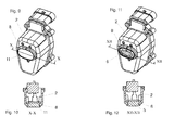
- Weitere Einzelheiten der Erfindung sind der Beispielsbeschreibung und den Zeichnungen zu entnehmen. Hierbei zeigen
- Fig. 1
- den Mehrfachdüsenkörper in perspektivischer Ansicht mit angedeutetem Spritzfächer aus einer Düse,
- Fig. 2
- den Mehrfachdüsenkörper in perspektivischer Ansicht,
- Fig. 3
- das Gehäuse der motorischen Verstellelemente in perspektivischer Ansicht,
- Fig. 4
- das Gehäuse der motorischen Verstellelemente in seitlicher Ansicht,
- Fig. 5
- das Gehäuse der motorischen Verstellelemente in der Ansicht V - V gemäß
Fig. 4 , - Fig. 6
- das Verschlusselement in vergrößerter Darstellung,
- Fig. 7
- die als LEDs ausgebildeten Lichtquellen in Vorderansicht und in vergrößerter Darstellung,
- Fig. 8
- die als LEDs ausgebildeten Lichtquellen in Rückansicht und in vergrößerter Darstellung,
- Fig. 9
- das Gehäuse der motorischen Verstellelemente in perspektivischer Ansicht mit Verschlusselement,
- Fig. 10
- das Gehäuse der motorischen Verstellelemente in Ansicht X - X aus
Fig. 9 , - Fig. 11
- das Gehäuse der motorischen Verstellelemente in perspektivischer Ansicht mit als LEDs ausgebildeten Lichtquellen und
- Fig. 12
- das Gehäuse der motorischen Verstelllemente in Ansicht XII - XII aus
Fig. 11 . - Der Mehrfachdüsenkörper weist das Mehrfachdüsenkörpergehäuse 1 auf. Im unteren Bereich des Gehäuses befindet sich das Gehäuse 2 der motorischen Verstellelemente des Mehrfachdüsenkörpers. Im oberen Bereich des Mehrfachdüsenkörpergehäuses 1 ist ein Teil 3 der Flüssigkeitsleitung, an welcher der Mehrfachdüsenkörper anschließbar ist, angeordnet. Über diese Flüssigkeitsleitung, die beispielsweise an einem Verteilergestänge einer landwirtschaftlichen Feldspritze angeordnet ist, ist dem jeweiligen Mehrfachdüsenkörper die auszubringende Flüssigkeit zuzuführen.
- Die Flüssigkeitsleitung 3 ist mit der in dem Mehrfachdüsenkörpergehäuse 1 angeordneten, nicht dargestellten Zuleitung verbunden. Die Zuleitung mündet in einem in dem Mehrfachdüsenkörpergehäuse 1 angeordneten, nicht dargestellten Verteilerraum aus. Von diesem Verteilerraum führen, gemäß des Ausführungsbeispieles, vier nicht dargestellte Verbindungsleitungen zu den vier Anschlussstücken 4 der Ausbringdüsen 5, von denen eines in
Fig. 1 nicht zu sehen ist und von denen zwei inFig. 2 nicht zu sehen sind, die mittig in zumindest annähernd gleichmäßiger Weise um das Mehrfachdüsenkörpergehäuse 1 herum angeordnet sind. - Die Verbindungsleitungen sind im Bereich des Verteilerraumes mittels nicht dargestellter Absperrelemente abzusperren. Über diese Absperrelemente sind die Verbindungsleitungen mit der Zuleitung wahlweise verbindbar und/oder ihr gegenüber absperrbar. Die Absperrelemente sind über ein schaltbares, nicht dargestellte motorische Verstellelement, welches als Elektromotor ausgebildet ist, der sich im Gehäuse 2 der motorischen Verstellelemente befindet, betätigbar und somit in die jeweilige Absperr- oder Durchflussposition zu bringen.
- Das als Elektromotor ausgebildete, motorische Verstellelement, welches in dem Gehäuse 2 angeordnet ist, ist über nicht dargestellte Verbindungsleitungen mit einer Stromversorgung und einer Steuerungseinrichtung, welche beispielsweise als Bordcomputer ausgebildet sein kann, verbunden.
- Die als LEDs ausgebildeten Lichtquellen 6 sind zumindest annähernd mittig an der Unterseite des Gehäuses 2 der motorischen Verstellelemente in einem Lichtgehäuse 7 in der als Aussparung in dem Gehäuse 2 ausgebildeten Aufnahmevorrichtung 8 angeordnet. Von dort aus bilden sie Lichtkegel aus, die jeweils den Sprühfächer 9 der zugeordneten Düse 5 des Mehrfachdüsenkörpers beleuchten, derart, dass die zugeordneten Lichtquellen 6 in Betrieb genommen werden, wenn über die jeweilige Düse Mittel ausgebracht werden. Das heißt, eine zugeordnete Lichtquelle 6 wird dann zum Leuchten gebracht, wenn die betreffende Düse über die Verbindungsleitung mit der Zuleitung verbunden ist und über somit über die Düse Mittel ausgebracht werden.
- An der Rückseite des Lichtgehäuses 7 der drei als LEDs ausgebildeten Lichtquellen 6 befinden sich als elektrische Steckkontakte 10 ausgebildete Verbindungselemente, mit denen die Energieversorgung der Lichtquellen 6 über die Energieversorgung der motorischen Verstellelemente erfolgt.
- Anstatt der in einem Lichtgehäuse 7 befindlichen als LEDs ausgebildeten Lichtquellen 6, kann ein Verschlusselement 11 in die als Aussparung in dem Gehäuse 2 ausgebildeten Aufnahmevorrichtung 8 angeordnet werden. Dadurch lässt sich das Eindringen von insbesondere Schmutz und anderen Fremdkörpern in die Aufnahmevorrichtung 8 verhindern.
Claims (7)
- Mehrfachdüsenkörper mit mehreren Ausbringdüsen (5) zur Anordnung an der Flüssigkeitsleitung (3) einer landwirtschaftlichen Feldspritze mit einem Gehäuse (1), an dem die Ausbringdüsen (5) angeordnet und in welchem Verstellelemente zum Aktivieren und Deaktivieren der Ausbringdüsen (5) angeordnet sind, dadurch gekennzeichnet, dass zumindest einigen der Ausbringdüsen (5) eine den von der Ausbringdüse (5) ausgestoßenen Flüssigkeitsfächer (9) beleuchtende Lichtquelle (6) zugeordnet ist, wobei die Lichtquellen (6) zumindest annähernd mittig zwischen den Ausbringdüsen (5) in dem Gehäuse (2) der Verstellelemente angeordnet sind.
- Mehrfachdüsenkörper nach Anspruch 1, dadurch gekennzeichnet, dass elektrische Verbindungselemente zur Energieversorgung der Lichtquellen (6) vorgesehen sind.
- Mehrfachdüsenkörper nach Anspruch 2, dadurch gekennzeichnet, dass die Energieversorgung der Lichtquellen (6) mit der Versorgungsleitung der Verstellelemente verbindbar ist.
- Mehrfachdüsenkörper nach Anspruch 2, dadurch gekennzeichnet, dass die Lichtquellen (6) herausnehmbar und durch ein Verschlusselement (11) austauschbar sind.
- Mehrfachdüsenkörper nach Anspruch 1, dadurch gekennzeichnet, dass jeder Düse (5) des Mehrfachdüsenkörpers eine oder mehrere Lichtquellen (6) zugeordnet sind.
- Mehrfachdüsenkörper nach Anspruch 5, dadurch gekennzeichnet, dass die zugeordneten Lichtquellen (6) in Betrieb nehmbar sind, wenn über die Düse (5) Mittel ausgebracht werden.
- Mehrfachdüsenkörper nach zumindest einem der vorstehenden Ansprüche, wobei die Ausbringdüsen (5) in zumindest annähernd regelmäßiger Weise um das Gehäuse (1) verteilt angeordnet sind, dadurch gekennzeichnet, dass die Lichtquelle (6) in zumindest annähernd gleichen Abständen zu den Ausbringdüsen (5) angeordnet ist.
Priority Applications (1)
| Application Number | Priority Date | Filing Date | Title |
|---|---|---|---|
| PL12401077T PL2522433T3 (pl) | 2011-05-10 | 2012-05-04 | Korpus wielodyszowy z oświetleniem |
Applications Claiming Priority (1)
| Application Number | Priority Date | Filing Date | Title |
|---|---|---|---|
| DE102011050234A DE102011050234A1 (de) | 2011-05-10 | 2011-05-10 | Mehrfachdüsenkörper |
Publications (2)
| Publication Number | Publication Date |
|---|---|
| EP2522433A1 true EP2522433A1 (de) | 2012-11-14 |
| EP2522433B1 EP2522433B1 (de) | 2018-10-03 |
Family
ID=46146798
Family Applications (1)
| Application Number | Title | Priority Date | Filing Date |
|---|---|---|---|
| EP12401077.8A Active EP2522433B1 (de) | 2011-05-10 | 2012-05-04 | Mehrfachdüsenkörper mit Beleuchtung |
Country Status (4)
| Country | Link |
|---|---|
| EP (1) | EP2522433B1 (de) |
| DE (1) | DE102011050234A1 (de) |
| DK (1) | DK2522433T3 (de) |
| PL (1) | PL2522433T3 (de) |
Cited By (5)
| Publication number | Priority date | Publication date | Assignee | Title |
|---|---|---|---|---|
| USD766399S1 (en) | 2014-10-03 | 2016-09-13 | Deere & Company | Hybrid spray nozzle turret |
| US9884330B2 (en) | 2014-06-20 | 2018-02-06 | Deere & Company | Broadband spray nozzle systems and methods |
| US10189031B2 (en) | 2014-06-20 | 2019-01-29 | Deere & Company | Hybrid flow nozzle and control system |
| US10773271B2 (en) | 2014-06-20 | 2020-09-15 | Deere & Company | Time varying control of the operation of spray systems |
| US12115546B2 (en) | 2014-06-20 | 2024-10-15 | Deere & Company | Hybrid flow nozzle system |
Families Citing this family (2)
| Publication number | Priority date | Publication date | Assignee | Title |
|---|---|---|---|---|
| DE102016124119A1 (de) * | 2016-12-13 | 2018-06-14 | Amazonen-Werke H. Dreyer Gmbh & Co. Kg | Feldspritze |
| EP4231821B1 (de) * | 2020-10-26 | 2026-04-08 | Precision Planting LLC | Sichtsystem |
Citations (3)
| Publication number | Priority date | Publication date | Assignee | Title |
|---|---|---|---|---|
| EP1961300A2 (de) | 2007-02-22 | 2008-08-27 | Amazonen-Werke H. Dreyer GmbH & Co. KG | Spritzeinrichtung |
| EP1661627B1 (de) | 2004-11-25 | 2009-05-13 | John Deere Fabriek Horst B.V. | Düsenvorrichtung |
| DE202009004872U1 (de) * | 2009-06-02 | 2009-08-20 | Herbert Dammann Gmbh | Spritzgerät |
-
2011
- 2011-05-10 DE DE102011050234A patent/DE102011050234A1/de not_active Withdrawn
-
2012
- 2012-05-04 EP EP12401077.8A patent/EP2522433B1/de active Active
- 2012-05-04 PL PL12401077T patent/PL2522433T3/pl unknown
- 2012-05-04 DK DK12401077.8T patent/DK2522433T3/en active
Patent Citations (3)
| Publication number | Priority date | Publication date | Assignee | Title |
|---|---|---|---|---|
| EP1661627B1 (de) | 2004-11-25 | 2009-05-13 | John Deere Fabriek Horst B.V. | Düsenvorrichtung |
| EP1961300A2 (de) | 2007-02-22 | 2008-08-27 | Amazonen-Werke H. Dreyer GmbH & Co. KG | Spritzeinrichtung |
| DE202009004872U1 (de) * | 2009-06-02 | 2009-08-20 | Herbert Dammann Gmbh | Spritzgerät |
Cited By (7)
| Publication number | Priority date | Publication date | Assignee | Title |
|---|---|---|---|---|
| US9884330B2 (en) | 2014-06-20 | 2018-02-06 | Deere & Company | Broadband spray nozzle systems and methods |
| US10189031B2 (en) | 2014-06-20 | 2019-01-29 | Deere & Company | Hybrid flow nozzle and control system |
| US10730065B2 (en) | 2014-06-20 | 2020-08-04 | Deere & Company | Hybrid flow nozzle system |
| US10773271B2 (en) | 2014-06-20 | 2020-09-15 | Deere & Company | Time varying control of the operation of spray systems |
| US10994297B2 (en) | 2014-06-20 | 2021-05-04 | Deere & Company | Hybrid spray apparatus |
| US12115546B2 (en) | 2014-06-20 | 2024-10-15 | Deere & Company | Hybrid flow nozzle system |
| USD766399S1 (en) | 2014-10-03 | 2016-09-13 | Deere & Company | Hybrid spray nozzle turret |
Also Published As
| Publication number | Publication date |
|---|---|
| DK2522433T3 (en) | 2019-01-21 |
| PL2522433T3 (pl) | 2019-03-29 |
| EP2522433B1 (de) | 2018-10-03 |
| DE102011050234A1 (de) | 2012-11-15 |
Similar Documents
| Publication | Publication Date | Title |
|---|---|---|
| EP2522433B1 (de) | Mehrfachdüsenkörper mit Beleuchtung | |
| EP1961300B1 (de) | Feldspritze | |
| EP2522432A1 (de) | Mehrfachdüsenkörper mit Beleuchtung | |
| DE2901493A1 (de) | Landmaschine | |
| DE102009031066A1 (de) | Verteiler für pneumatische Drillmaschine | |
| DE102012101013B4 (de) | Pflanzenschutzspritze | |
| EP2567617B1 (de) | Landwirtschaftliche Feldspritze mit Mehrfachdüsenkörpern | |
| DE202009004872U1 (de) | Spritzgerät | |
| EP2567607B1 (de) | Bedienungseinrichtung für landwirtschaftliche Verteilmaschinen | |
| EP2570027A2 (de) | Mehrfachdüsenkörper für eine landwirtschaftliche Feldspritze | |
| EP2705750B1 (de) | Schleppschlauchverband | |
| EP3078249B1 (de) | Verteilmaschine, insbesondere für die landwirtschaft | |
| DE102013101449A1 (de) | Zentrifugalstreuer | |
| EP1166615A1 (de) | Reinigungseinrichtung und Mähwerk | |
| DE102013101448A1 (de) | Verteilmaschine, insbesondere für die Landwirtschaft | |
| DE4130817C2 (de) | Fahrbare Gülle-Ausbringvorrichtung | |
| EP0223224B1 (de) | Landwirtschaftliche Feldspritze | |
| EP3485728B1 (de) | Landwirtschaftliche verteilmaschine | |
| DE4441472A1 (de) | Feldspritze | |
| DE102023209350A1 (de) | Ventilbaugruppe für eine Pflanzenbehandlungsvorrichtung | |
| DE102017110564A1 (de) | Mehrfachdüsenkörper | |
| DE102012108327A1 (de) | Drehpflug | |
| DE102023105531A1 (de) | Landwirtschaftliche Spritzeinrichtung | |
| DE102017110565A1 (de) | Mehrfachdüsenkörper | |
| DE1967465U (de) | Geraet zur behandlung von pflanzen mittels durch eine abtastvorrichtung ausgeloester strahlen. |
Legal Events
| Date | Code | Title | Description |
|---|---|---|---|
| PUAI | Public reference made under article 153(3) epc to a published international application that has entered the european phase |
Free format text: ORIGINAL CODE: 0009012 |
|
| AK | Designated contracting states |
Kind code of ref document: A1 Designated state(s): AL AT BE BG CH CY CZ DE DK EE ES FI FR GB GR HR HU IE IS IT LI LT LU LV MC MK MT NL NO PL PT RO RS SE SI SK SM TR |
|
| AX | Request for extension of the european patent |
Extension state: BA ME |
|
| 17P | Request for examination filed |
Effective date: 20130326 |
|
| STAA | Information on the status of an ep patent application or granted ep patent |
Free format text: STATUS: EXAMINATION IS IN PROGRESS |
|
| 17Q | First examination report despatched |
Effective date: 20171102 |
|
| REG | Reference to a national code |
Ref country code: DE Ref legal event code: R079 Ref document number: 502012013537 Country of ref document: DE Free format text: PREVIOUS MAIN CLASS: B05B0001160000 Ipc: A01M0007000000 |
|
| GRAP | Despatch of communication of intention to grant a patent |
Free format text: ORIGINAL CODE: EPIDOSNIGR1 |
|
| STAA | Information on the status of an ep patent application or granted ep patent |
Free format text: STATUS: GRANT OF PATENT IS INTENDED |
|
| RIC1 | Information provided on ipc code assigned before grant |
Ipc: F21W 121/02 20060101ALN20180504BHEP Ipc: F21Y 115/10 20160101ALN20180504BHEP Ipc: F21V 33/00 20060101ALI20180504BHEP Ipc: A01M 7/00 20060101AFI20180504BHEP Ipc: B05B 1/16 20060101ALI20180504BHEP Ipc: B05B 1/04 20060101ALI20180504BHEP Ipc: B05B 15/00 20060101ALI20180504BHEP Ipc: B05B 1/20 20060101ALI20180504BHEP |
|
| INTG | Intention to grant announced |
Effective date: 20180530 |
|
| GRAS | Grant fee paid |
Free format text: ORIGINAL CODE: EPIDOSNIGR3 |
|
| GRAA | (expected) grant |
Free format text: ORIGINAL CODE: 0009210 |
|
| STAA | Information on the status of an ep patent application or granted ep patent |
Free format text: STATUS: THE PATENT HAS BEEN GRANTED |
|
| AK | Designated contracting states |
Kind code of ref document: B1 Designated state(s): AL AT BE BG CH CY CZ DE DK EE ES FI FR GB GR HR HU IE IS IT LI LT LU LV MC MK MT NL NO PL PT RO RS SE SI SK SM TR |
|
| REG | Reference to a national code |
Ref country code: GB Ref legal event code: FG4D Free format text: NOT ENGLISH |
|
| REG | Reference to a national code |
Ref country code: CH Ref legal event code: EP Ref country code: AT Ref legal event code: REF Ref document number: 1047626 Country of ref document: AT Kind code of ref document: T Effective date: 20181015 |
|
| REG | Reference to a national code |
Ref country code: IE Ref legal event code: FG4D Free format text: LANGUAGE OF EP DOCUMENT: GERMAN Ref country code: DE Ref legal event code: R096 Ref document number: 502012013537 Country of ref document: DE |
|
| REG | Reference to a national code |
Ref country code: NL Ref legal event code: FP |
|
| REG | Reference to a national code |
Ref country code: DK Ref legal event code: T3 Effective date: 20190109 |
|
| REG | Reference to a national code |
Ref country code: LT Ref legal event code: MG4D |
|
| PG25 | Lapsed in a contracting state [announced via postgrant information from national office to epo] |
Ref country code: IS Free format text: LAPSE BECAUSE OF FAILURE TO SUBMIT A TRANSLATION OF THE DESCRIPTION OR TO PAY THE FEE WITHIN THE PRESCRIBED TIME-LIMIT Effective date: 20190203 Ref country code: FI Free format text: LAPSE BECAUSE OF FAILURE TO SUBMIT A TRANSLATION OF THE DESCRIPTION OR TO PAY THE FEE WITHIN THE PRESCRIBED TIME-LIMIT Effective date: 20181003 Ref country code: LV Free format text: LAPSE BECAUSE OF FAILURE TO SUBMIT A TRANSLATION OF THE DESCRIPTION OR TO PAY THE FEE WITHIN THE PRESCRIBED TIME-LIMIT Effective date: 20181003 Ref country code: LT Free format text: LAPSE BECAUSE OF FAILURE TO SUBMIT A TRANSLATION OF THE DESCRIPTION OR TO PAY THE FEE WITHIN THE PRESCRIBED TIME-LIMIT Effective date: 20181003 Ref country code: NO Free format text: LAPSE BECAUSE OF FAILURE TO SUBMIT A TRANSLATION OF THE DESCRIPTION OR TO PAY THE FEE WITHIN THE PRESCRIBED TIME-LIMIT Effective date: 20190103 Ref country code: HR Free format text: LAPSE BECAUSE OF FAILURE TO SUBMIT A TRANSLATION OF THE DESCRIPTION OR TO PAY THE FEE WITHIN THE PRESCRIBED TIME-LIMIT Effective date: 20181003 Ref country code: CZ Free format text: LAPSE BECAUSE OF FAILURE TO SUBMIT A TRANSLATION OF THE DESCRIPTION OR TO PAY THE FEE WITHIN THE PRESCRIBED TIME-LIMIT Effective date: 20181003 Ref country code: BG Free format text: LAPSE BECAUSE OF FAILURE TO SUBMIT A TRANSLATION OF THE DESCRIPTION OR TO PAY THE FEE WITHIN THE PRESCRIBED TIME-LIMIT Effective date: 20190103 Ref country code: ES Free format text: LAPSE BECAUSE OF FAILURE TO SUBMIT A TRANSLATION OF THE DESCRIPTION OR TO PAY THE FEE WITHIN THE PRESCRIBED TIME-LIMIT Effective date: 20181003 |
|
| PG25 | Lapsed in a contracting state [announced via postgrant information from national office to epo] |
Ref country code: PT Free format text: LAPSE BECAUSE OF FAILURE TO SUBMIT A TRANSLATION OF THE DESCRIPTION OR TO PAY THE FEE WITHIN THE PRESCRIBED TIME-LIMIT Effective date: 20190203 Ref country code: AL Free format text: LAPSE BECAUSE OF FAILURE TO SUBMIT A TRANSLATION OF THE DESCRIPTION OR TO PAY THE FEE WITHIN THE PRESCRIBED TIME-LIMIT Effective date: 20181003 Ref country code: SE Free format text: LAPSE BECAUSE OF FAILURE TO SUBMIT A TRANSLATION OF THE DESCRIPTION OR TO PAY THE FEE WITHIN THE PRESCRIBED TIME-LIMIT Effective date: 20181003 Ref country code: GR Free format text: LAPSE BECAUSE OF FAILURE TO SUBMIT A TRANSLATION OF THE DESCRIPTION OR TO PAY THE FEE WITHIN THE PRESCRIBED TIME-LIMIT Effective date: 20190104 Ref country code: RS Free format text: LAPSE BECAUSE OF FAILURE TO SUBMIT A TRANSLATION OF THE DESCRIPTION OR TO PAY THE FEE WITHIN THE PRESCRIBED TIME-LIMIT Effective date: 20181003 |
|
| REG | Reference to a national code |
Ref country code: DE Ref legal event code: R097 Ref document number: 502012013537 Country of ref document: DE |
|
| PLBE | No opposition filed within time limit |
Free format text: ORIGINAL CODE: 0009261 |
|
| STAA | Information on the status of an ep patent application or granted ep patent |
Free format text: STATUS: NO OPPOSITION FILED WITHIN TIME LIMIT |
|
| PG25 | Lapsed in a contracting state [announced via postgrant information from national office to epo] |
Ref country code: SM Free format text: LAPSE BECAUSE OF FAILURE TO SUBMIT A TRANSLATION OF THE DESCRIPTION OR TO PAY THE FEE WITHIN THE PRESCRIBED TIME-LIMIT Effective date: 20181003 Ref country code: EE Free format text: LAPSE BECAUSE OF FAILURE TO SUBMIT A TRANSLATION OF THE DESCRIPTION OR TO PAY THE FEE WITHIN THE PRESCRIBED TIME-LIMIT Effective date: 20181003 Ref country code: RO Free format text: LAPSE BECAUSE OF FAILURE TO SUBMIT A TRANSLATION OF THE DESCRIPTION OR TO PAY THE FEE WITHIN THE PRESCRIBED TIME-LIMIT Effective date: 20181003 Ref country code: SK Free format text: LAPSE BECAUSE OF FAILURE TO SUBMIT A TRANSLATION OF THE DESCRIPTION OR TO PAY THE FEE WITHIN THE PRESCRIBED TIME-LIMIT Effective date: 20181003 |
|
| 26N | No opposition filed |
Effective date: 20190704 |
|
| PG25 | Lapsed in a contracting state [announced via postgrant information from national office to epo] |
Ref country code: SI Free format text: LAPSE BECAUSE OF FAILURE TO SUBMIT A TRANSLATION OF THE DESCRIPTION OR TO PAY THE FEE WITHIN THE PRESCRIBED TIME-LIMIT Effective date: 20181003 |
|
| REG | Reference to a national code |
Ref country code: CH Ref legal event code: PL |
|
| GBPC | Gb: european patent ceased through non-payment of renewal fee |
Effective date: 20190504 |
|
| PG25 | Lapsed in a contracting state [announced via postgrant information from national office to epo] |
Ref country code: CH Free format text: LAPSE BECAUSE OF NON-PAYMENT OF DUE FEES Effective date: 20190531 Ref country code: LI Free format text: LAPSE BECAUSE OF NON-PAYMENT OF DUE FEES Effective date: 20190531 Ref country code: MC Free format text: LAPSE BECAUSE OF FAILURE TO SUBMIT A TRANSLATION OF THE DESCRIPTION OR TO PAY THE FEE WITHIN THE PRESCRIBED TIME-LIMIT Effective date: 20181003 |
|
| REG | Reference to a national code |
Ref country code: BE Ref legal event code: MM Effective date: 20190531 |
|
| PG25 | Lapsed in a contracting state [announced via postgrant information from national office to epo] |
Ref country code: LU Free format text: LAPSE BECAUSE OF NON-PAYMENT OF DUE FEES Effective date: 20190504 |
|
| PG25 | Lapsed in a contracting state [announced via postgrant information from national office to epo] |
Ref country code: TR Free format text: LAPSE BECAUSE OF FAILURE TO SUBMIT A TRANSLATION OF THE DESCRIPTION OR TO PAY THE FEE WITHIN THE PRESCRIBED TIME-LIMIT Effective date: 20181003 |
|
| PG25 | Lapsed in a contracting state [announced via postgrant information from national office to epo] |
Ref country code: IE Free format text: LAPSE BECAUSE OF NON-PAYMENT OF DUE FEES Effective date: 20190504 Ref country code: GB Free format text: LAPSE BECAUSE OF NON-PAYMENT OF DUE FEES Effective date: 20190504 |
|
| PG25 | Lapsed in a contracting state [announced via postgrant information from national office to epo] |
Ref country code: BE Free format text: LAPSE BECAUSE OF NON-PAYMENT OF DUE FEES Effective date: 20190531 |
|
| REG | Reference to a national code |
Ref country code: AT Ref legal event code: MM01 Ref document number: 1047626 Country of ref document: AT Kind code of ref document: T Effective date: 20190504 |
|
| PG25 | Lapsed in a contracting state [announced via postgrant information from national office to epo] |
Ref country code: AT Free format text: LAPSE BECAUSE OF NON-PAYMENT OF DUE FEES Effective date: 20190504 |
|
| REG | Reference to a national code |
Ref country code: DE Ref legal event code: R081 Ref document number: 502012013537 Country of ref document: DE Owner name: AMAZONEN-WERKE H. DREYER SE & CO. KG, DE Free format text: FORMER OWNER: AMAZONEN-WERKE H. DREYER GMBH & CO. KG, 49205 HASBERGEN, DE |
|
| PG25 | Lapsed in a contracting state [announced via postgrant information from national office to epo] |
Ref country code: CY Free format text: LAPSE BECAUSE OF FAILURE TO SUBMIT A TRANSLATION OF THE DESCRIPTION OR TO PAY THE FEE WITHIN THE PRESCRIBED TIME-LIMIT Effective date: 20181003 |
|
| PG25 | Lapsed in a contracting state [announced via postgrant information from national office to epo] |
Ref country code: HU Free format text: LAPSE BECAUSE OF FAILURE TO SUBMIT A TRANSLATION OF THE DESCRIPTION OR TO PAY THE FEE WITHIN THE PRESCRIBED TIME-LIMIT; INVALID AB INITIO Effective date: 20120504 Ref country code: MT Free format text: LAPSE BECAUSE OF FAILURE TO SUBMIT A TRANSLATION OF THE DESCRIPTION OR TO PAY THE FEE WITHIN THE PRESCRIBED TIME-LIMIT Effective date: 20181003 |
|
| PG25 | Lapsed in a contracting state [announced via postgrant information from national office to epo] |
Ref country code: MK Free format text: LAPSE BECAUSE OF FAILURE TO SUBMIT A TRANSLATION OF THE DESCRIPTION OR TO PAY THE FEE WITHIN THE PRESCRIBED TIME-LIMIT Effective date: 20181003 |
|
| P01 | Opt-out of the competence of the unified patent court (upc) registered |
Effective date: 20230523 |
|
| PGFP | Annual fee paid to national office [announced via postgrant information from national office to epo] |
Ref country code: DE Payment date: 20250311 Year of fee payment: 14 |
|
| PGFP | Annual fee paid to national office [announced via postgrant information from national office to epo] |
Ref country code: DK Payment date: 20250516 Year of fee payment: 14 |
|
| PGFP | Annual fee paid to national office [announced via postgrant information from national office to epo] |
Ref country code: IT Payment date: 20250422 Year of fee payment: 14 |
|
| PGFP | Annual fee paid to national office [announced via postgrant information from national office to epo] |
Ref country code: NL Payment date: 20260317 Year of fee payment: 15 |
|
| PGFP | Annual fee paid to national office [announced via postgrant information from national office to epo] |
Ref country code: FR Payment date: 20260309 Year of fee payment: 15 |
|
| PGFP | Annual fee paid to national office [announced via postgrant information from national office to epo] |
Ref country code: PL Payment date: 20260313 Year of fee payment: 15 |