EP2522306B1 - Stentimplantatklappe zur Verhinderung von Querschnittslähmung - Google Patents
Stentimplantatklappe zur Verhinderung von Querschnittslähmung Download PDFInfo
- Publication number
- EP2522306B1 EP2522306B1 EP20120275060 EP12275060A EP2522306B1 EP 2522306 B1 EP2522306 B1 EP 2522306B1 EP 20120275060 EP20120275060 EP 20120275060 EP 12275060 A EP12275060 A EP 12275060A EP 2522306 B1 EP2522306 B1 EP 2522306B1
- Authority
- EP
- European Patent Office
- Prior art keywords
- stent graft
- edge
- proximal
- stent
- valve
- Prior art date
- Legal status (The legal status is an assumption and is not a legal conclusion. Google has not performed a legal analysis and makes no representation as to the accuracy of the status listed.)
- Active
Links
Images






Classifications
-
- A—HUMAN NECESSITIES
- A61—MEDICAL OR VETERINARY SCIENCE; HYGIENE
- A61F—FILTERS IMPLANTABLE INTO BLOOD VESSELS; PROSTHESES; DEVICES PROVIDING PATENCY TO, OR PREVENTING COLLAPSING OF, TUBULAR STRUCTURES OF THE BODY, e.g. STENTS; ORTHOPAEDIC, NURSING OR CONTRACEPTIVE DEVICES; FOMENTATION; TREATMENT OR PROTECTION OF EYES OR EARS; BANDAGES, DRESSINGS OR ABSORBENT PADS; FIRST-AID KITS
- A61F2/00—Filters implantable into blood vessels; Prostheses, i.e. artificial substitutes or replacements for parts of the body; Appliances for connecting them with the body; Devices providing patency to, or preventing collapsing of, tubular structures of the body, e.g. stents
- A61F2/02—Prostheses implantable into the body
- A61F2/04—Hollow or tubular parts of organs, e.g. bladders, tracheae, bronchi or bile ducts
- A61F2/06—Blood vessels
- A61F2/07—Stent-grafts
-
- A—HUMAN NECESSITIES
- A61—MEDICAL OR VETERINARY SCIENCE; HYGIENE
- A61F—FILTERS IMPLANTABLE INTO BLOOD VESSELS; PROSTHESES; DEVICES PROVIDING PATENCY TO, OR PREVENTING COLLAPSING OF, TUBULAR STRUCTURES OF THE BODY, e.g. STENTS; ORTHOPAEDIC, NURSING OR CONTRACEPTIVE DEVICES; FOMENTATION; TREATMENT OR PROTECTION OF EYES OR EARS; BANDAGES, DRESSINGS OR ABSORBENT PADS; FIRST-AID KITS
- A61F2/00—Filters implantable into blood vessels; Prostheses, i.e. artificial substitutes or replacements for parts of the body; Appliances for connecting them with the body; Devices providing patency to, or preventing collapsing of, tubular structures of the body, e.g. stents
- A61F2/82—Devices providing patency to, or preventing collapsing of, tubular structures of the body, e.g. stents
- A61F2/86—Stents in a form characterised by the wire-like elements; Stents in the form characterised by a net-like or mesh-like structure
- A61F2/89—Stents in a form characterised by the wire-like elements; Stents in the form characterised by a net-like or mesh-like structure the wire-like elements comprising two or more adjacent rings flexibly connected by separate members
-
- A—HUMAN NECESSITIES
- A61—MEDICAL OR VETERINARY SCIENCE; HYGIENE
- A61F—FILTERS IMPLANTABLE INTO BLOOD VESSELS; PROSTHESES; DEVICES PROVIDING PATENCY TO, OR PREVENTING COLLAPSING OF, TUBULAR STRUCTURES OF THE BODY, e.g. STENTS; ORTHOPAEDIC, NURSING OR CONTRACEPTIVE DEVICES; FOMENTATION; TREATMENT OR PROTECTION OF EYES OR EARS; BANDAGES, DRESSINGS OR ABSORBENT PADS; FIRST-AID KITS
- A61F2/00—Filters implantable into blood vessels; Prostheses, i.e. artificial substitutes or replacements for parts of the body; Appliances for connecting them with the body; Devices providing patency to, or preventing collapsing of, tubular structures of the body, e.g. stents
- A61F2/95—Instruments specially adapted for placement or removal of stents or stent-grafts
- A61F2/954—Instruments specially adapted for placement or removal of stents or stent-grafts for placing stents or stent-grafts in a bifurcation
-
- A—HUMAN NECESSITIES
- A61—MEDICAL OR VETERINARY SCIENCE; HYGIENE
- A61F—FILTERS IMPLANTABLE INTO BLOOD VESSELS; PROSTHESES; DEVICES PROVIDING PATENCY TO, OR PREVENTING COLLAPSING OF, TUBULAR STRUCTURES OF THE BODY, e.g. STENTS; ORTHOPAEDIC, NURSING OR CONTRACEPTIVE DEVICES; FOMENTATION; TREATMENT OR PROTECTION OF EYES OR EARS; BANDAGES, DRESSINGS OR ABSORBENT PADS; FIRST-AID KITS
- A61F2/00—Filters implantable into blood vessels; Prostheses, i.e. artificial substitutes or replacements for parts of the body; Appliances for connecting them with the body; Devices providing patency to, or preventing collapsing of, tubular structures of the body, e.g. stents
- A61F2/95—Instruments specially adapted for placement or removal of stents or stent-grafts
- A61F2/958—Inflatable balloons for placing stents or stent-grafts
-
- A—HUMAN NECESSITIES
- A61—MEDICAL OR VETERINARY SCIENCE; HYGIENE
- A61F—FILTERS IMPLANTABLE INTO BLOOD VESSELS; PROSTHESES; DEVICES PROVIDING PATENCY TO, OR PREVENTING COLLAPSING OF, TUBULAR STRUCTURES OF THE BODY, e.g. STENTS; ORTHOPAEDIC, NURSING OR CONTRACEPTIVE DEVICES; FOMENTATION; TREATMENT OR PROTECTION OF EYES OR EARS; BANDAGES, DRESSINGS OR ABSORBENT PADS; FIRST-AID KITS
- A61F2/00—Filters implantable into blood vessels; Prostheses, i.e. artificial substitutes or replacements for parts of the body; Appliances for connecting them with the body; Devices providing patency to, or preventing collapsing of, tubular structures of the body, e.g. stents
- A61F2/02—Prostheses implantable into the body
- A61F2/04—Hollow or tubular parts of organs, e.g. bladders, tracheae, bronchi or bile ducts
- A61F2/06—Blood vessels
- A61F2002/061—Blood vessels provided with means for allowing access to secondary lumens
-
- A—HUMAN NECESSITIES
- A61—MEDICAL OR VETERINARY SCIENCE; HYGIENE
- A61F—FILTERS IMPLANTABLE INTO BLOOD VESSELS; PROSTHESES; DEVICES PROVIDING PATENCY TO, OR PREVENTING COLLAPSING OF, TUBULAR STRUCTURES OF THE BODY, e.g. STENTS; ORTHOPAEDIC, NURSING OR CONTRACEPTIVE DEVICES; FOMENTATION; TREATMENT OR PROTECTION OF EYES OR EARS; BANDAGES, DRESSINGS OR ABSORBENT PADS; FIRST-AID KITS
- A61F2/00—Filters implantable into blood vessels; Prostheses, i.e. artificial substitutes or replacements for parts of the body; Appliances for connecting them with the body; Devices providing patency to, or preventing collapsing of, tubular structures of the body, e.g. stents
- A61F2/02—Prostheses implantable into the body
- A61F2/04—Hollow or tubular parts of organs, e.g. bladders, tracheae, bronchi or bile ducts
- A61F2/06—Blood vessels
- A61F2/07—Stent-grafts
- A61F2002/075—Stent-grafts the stent being loosely attached to the graft material, e.g. by stitching
-
- A—HUMAN NECESSITIES
- A61—MEDICAL OR VETERINARY SCIENCE; HYGIENE
- A61F—FILTERS IMPLANTABLE INTO BLOOD VESSELS; PROSTHESES; DEVICES PROVIDING PATENCY TO, OR PREVENTING COLLAPSING OF, TUBULAR STRUCTURES OF THE BODY, e.g. STENTS; ORTHOPAEDIC, NURSING OR CONTRACEPTIVE DEVICES; FOMENTATION; TREATMENT OR PROTECTION OF EYES OR EARS; BANDAGES, DRESSINGS OR ABSORBENT PADS; FIRST-AID KITS
- A61F2230/00—Geometry of prostheses classified in groups A61F2/00 - A61F2/26 or A61F2/82 or A61F9/00 or A61F11/00 or subgroups thereof
- A61F2230/0002—Two-dimensional shapes, e.g. cross-sections
- A61F2230/0017—Angular shapes
- A61F2230/0019—Angular shapes rectangular
-
- A—HUMAN NECESSITIES
- A61—MEDICAL OR VETERINARY SCIENCE; HYGIENE
- A61F—FILTERS IMPLANTABLE INTO BLOOD VESSELS; PROSTHESES; DEVICES PROVIDING PATENCY TO, OR PREVENTING COLLAPSING OF, TUBULAR STRUCTURES OF THE BODY, e.g. STENTS; ORTHOPAEDIC, NURSING OR CONTRACEPTIVE DEVICES; FOMENTATION; TREATMENT OR PROTECTION OF EYES OR EARS; BANDAGES, DRESSINGS OR ABSORBENT PADS; FIRST-AID KITS
- A61F2250/00—Special features of prostheses classified in groups A61F2/00 - A61F2/26 or A61F2/82 or A61F9/00 or A61F11/00 or subgroups thereof
- A61F2250/0014—Special features of prostheses classified in groups A61F2/00 - A61F2/26 or A61F2/82 or A61F9/00 or A61F11/00 or subgroups thereof having different values of a given property or geometrical feature, e.g. mechanical property or material property, at different locations within the same prosthesis
- A61F2250/0037—Special features of prostheses classified in groups A61F2/00 - A61F2/26 or A61F2/82 or A61F9/00 or A61F11/00 or subgroups thereof having different values of a given property or geometrical feature, e.g. mechanical property or material property, at different locations within the same prosthesis differing in height or in length
-
- A—HUMAN NECESSITIES
- A61—MEDICAL OR VETERINARY SCIENCE; HYGIENE
- A61F—FILTERS IMPLANTABLE INTO BLOOD VESSELS; PROSTHESES; DEVICES PROVIDING PATENCY TO, OR PREVENTING COLLAPSING OF, TUBULAR STRUCTURES OF THE BODY, e.g. STENTS; ORTHOPAEDIC, NURSING OR CONTRACEPTIVE DEVICES; FOMENTATION; TREATMENT OR PROTECTION OF EYES OR EARS; BANDAGES, DRESSINGS OR ABSORBENT PADS; FIRST-AID KITS
- A61F2250/00—Special features of prostheses classified in groups A61F2/00 - A61F2/26 or A61F2/82 or A61F9/00 or A61F11/00 or subgroups thereof
- A61F2250/0014—Special features of prostheses classified in groups A61F2/00 - A61F2/26 or A61F2/82 or A61F9/00 or A61F11/00 or subgroups thereof having different values of a given property or geometrical feature, e.g. mechanical property or material property, at different locations within the same prosthesis
- A61F2250/0039—Special features of prostheses classified in groups A61F2/00 - A61F2/26 or A61F2/82 or A61F9/00 or A61F11/00 or subgroups thereof having different values of a given property or geometrical feature, e.g. mechanical property or material property, at different locations within the same prosthesis differing in diameter
Definitions
- This invention relates to a medical device and more particularly to an implantable endovascular device.
- US 2005/0059923 A1 discloses a fenestration with intrinsic means of selective closure incorporated to a tubular body and used in interventional cardiovascular procedures.
- This invention will be discussed in general with respect to aortic aneurysms and the use of an implantable device such as a stent graft to bridge an aneurysm and in particular in the descending aorta but the invention is not so limited and may be used for any region of the human or animal body and any type of implantable device.
- a stent graft can be used to bridge an aortic aneurysm but where there are side branch arteries from the aorta it is necessary to have side branches extending from the stent graft to give a blood supply to as many side branch arteries as possible.
- the human or animal body can in time adapt to lack of blood supply from some arteries which are occluded by the stent graft.
- blood supply via the intercostal arteries to the spinal cord can be alternatively achieved via other arteries such as for instance the celiac artery, the superior mesenteric artery, lumbar and internal iliac arteries.
- a stent graft as in claim 1.
- one of the underlap and overlap portions comprises a sheet of biocompatible graft material attached to the wall portion.
- the exit mouth is substantially crescent shaped when in the open condition.
- the proximal end of the stent graft has a selected diameter and the valve portion has a reduced diameter, the reduced diameter less than the selected diameter.
- the support wire is an inverted U-shape when the proximal end is orientated above the distal end.
- the stent graft further comprises a guide wire extending from beyond the distal end through the valve portion and through the vent lumen and out through the exit mouth, the guide wire provided for guiding a valve opening device.
- a stent graft defining a main lumen bounded by a wall of biocompatible graft material, the stent graft having a proximal end and a distal end and a valve portion between the proximal and distal ends, the valve portion formed by a wall portion having a part-circumferential double layer portion comprising an inner underlap portion and an outer overlap portion, the double layer portion forming a passageway parallel to the main lumen, the passageway having an entrance mouth and an exit mouth, the exit mouth closer to the proximal end of the stent graft than the entrance mouth, the passageway having a closed condition where the underlap and overlap portions are in contact and an open condition where the underlap and overlap portions are spaced apart to form a vent lumen, wherein the exit mouth is substantially crescent shaped when in the open condition.
- the stent graft further comprises a guide wire extending from beyond the distal end through the valve portion and through the vent lumen and out through the exit mouth, the guide wire provided for guiding a valve opening device.
- a stent graft for deployment into the aorta of a patient, the stent graft comprising a tubular body of a biocompatible graft material, the tubular body having a wall defining a main lumen therethrough, the tubular body comprising a proximal portion of a selected diameter and a portion of reduced diameter less than the selected diameter distal of the proximal portion and a proximal tapered portion extending between the proximal portion and the portion of reduced diameter, a plurality of low profile side arms in the portion of reduced diameter or the tapered portion, each low profile side arm comprising a respective side arm lumen therethrough and the main lumen being in fluid communication with the respective side arm lumens, the side arms being each for connection of an arm extension to an aortic branch vessel, a paraplegia prevention valve in fluid communication with the main lumen and open to external of the tubular body in a region defined by the portion of reduced diameter and the tapered portion, the valve formed by a
- the plurality low profile side arms in the portion of reduced diameter or the tapered portions comprise four low profile side arms, one each for a celiac artery, a superior mesenteric artery, a right renal artery and a left renal artery of a patient.
- the exit mouth is substantially crescent shaped when in the open condition.
- the stent graft further comprises a plurality of external zig zag stents longitudinally spaced apart on an outside surface of the wall of biocompatible graft material and at least one internal stent within the valve portion between the proximal and distal ends, the internal stent having at least first, second and third struts, the second strut extending between the first and third struts.
- the sheet comprises, a first edge, a second edge opposite the first edge, a distal edge and a proximal edge, the first edge sewn to the wall portion adjacent to the first strut of the at least one internal stent, the second edge sewn to the wall portion adjacent to the third strut of the at least one internal stent and the proximal edge sewn along a line between a pair of adjacent points of the strut, wherein the sheet is biased radially outwards by the second strut.
- the valve comprises a support wire extending between the pair of adjacent points of the strut.
- the support wire is an inverted U-shape when the proximal end is orientated above the distal end.
- a stent graft 10 according to a first embodiment of the invention is shown.
- the stent graft 10 will find many uses and will commonly form a part of a more complex stent graft such as the stent graft 100 shown in figure 13 .
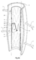
- Figures 4a and 4b show a perspective cut-away view of the stent graft 10 in situ within a descending aorta 5 having intercostals 7.
- the stent graft 10 has an exit mouth 69 that is not intended to be connected to a side branch artery of the aorta but is used to provide temporary perfusion to external of the stent graft 10 after deployment of the stent graft 10 into the aorta 5.
- the stent graft 10 shown in figure 1 comprises a tubular body 12 of a biocompatible graft material.
- the stent graft 10 defines a main lumen 11 and has a proximal portion 14 adjacent a proximal end 13 and a distal portion 20 adjacent a distal end 21.
- a valve portion 60 is formed between the proximal and distal portions 14, 20.
- the valve portion 60 is formed by a wall portion 62 having a part-circumferential double layer portion comprising an inner underlap portion 64 and an outer overlap portion 66 as can bee seen in figure 4a .
- the double layer portion forms a passageway parallel to the main lumen, the passageway having an entrance mouth 61 and an exit mouth 69 as is most clearly shown in figures 4a and 5 .
- the exit mouth 69 is closer to the proximal end 14 of the stent graft than the entrance mouth 61.
- the passageway has a closed condition where the underlap and overlap portions 64, 66 are in contact, as is shown in figure 4b , and an open condition where the underlap and overlap portions 64, 66 are spaced apart to form a vent lumen 40 as is shown in figure 5 .
- the wall portion is broken by a narrow cut or slot 70 as can been seen in figures 1 and 2 .
- the cut or slot 70 has a first edge 72 and a second edge 74, and the cut or slot is openable by relative radial movement of the first edge 72 away from the second edge 74.
- exit mouth 69 is substantially crescent shaped when in the open condition.
- a valve portion 60 can be seen from within the stent graft 10 in a cutaway view.
- the underlap and overlap portions 64, 66 comprise a sheet 80 of biocompatible graft material attached to the wall portion 62.
- Figure 4a shows a plurality of external zig zag stents 24 longitudinally spaced apart on an outside surface of the wall of biocompatible graft material.
- An internal stent 50 within the valve portion 60 is also provided.
- the internal stent 50 has first, second and third struts 52, 54, 56 with the second strut 54 extending between the first and third struts 52, 56.
- the internal stent is a nitinol (metal alloy of nickel and titanium) stent.
- stainless steel stents may be used in which case the struts 52, 54 and 56 would be substantially more parallel and more closely spaced within the graft than the nitinol stents struts shown in figures 3 and 4a .
- the sheet 80 is in the shape of a parallelogram and comprises a first edge 82, a second edge 84 opposite the first edge 82, a distal edge 86 and a proximal edge 88.
- the first edge 82 is sewn to the wall adjacent to the first strut 52 of the internal stent 50
- a second edge 84 is sewn to the wall adjacent to the third strut 56 of the internal stent 50
- the proximal edge 88 is sewn along a line between a pair of adjacent points 51, 55 of the internal stent 50.
- the sheet 80 is biased radially outwards by the second strut 54. This biases the valve into the closed condition as is shown in figure 4b .
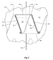
- a support wire 90 extending between the pair of adjacent points of the struts 51, 55 is shown in figure 3 .
- the support wire is an inverted U-shape when the stent graft 10 is viewed with its proximal end orientated above its distal end. Curled ends are provided to avoid puncture points.
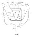
- a stent graft according to a second embodiment of the invention is shown. This embodiment is similar to the first embodiment except that the sheet 80 at the valve portion 60 is in the shape of a rectangle and the internal stent 50 is shaped differently with struts 52 and 54 orientated along a longitudinal axis of the stent graft 10.
- a stent graft according to a third embodiment of the invention is shown.
- This embodiment is similar to the second embodiment except that the support wire 90 is positioned adjacent to the entrance mouth 61. This may facilitate gaining access though the valve where the stent graft 10 has not been pre-loaded with a wire 105 or where the wire 105 has been extracted and it is desired to re-insert the wire 105.
- Other arrangements at the entrance mouth may be provide to facilitate such access.
- a stent graft according to a fourth embodiment of the invention is shown.
- This embodiment is similar to the second embodiment except that the internal stent 50 is "M" shaped having an two struts 54a and 54b biasing the sheet 80 radially outwards so as to bias the valve into the closed condition as is shown in figure 4b .
- a stent graft according to a fifth embodiment of the invention is shown.
- the sheet 80 is located outside of the lumen 11 rather than inside the lumen 11.
- the narrow cut or slot 70 forms the entrance mouth 61 rather than the exit mouth 69.
- a smooth internal wall to the lumen 11 is provided.
- a stent graft according to a sixth embodiment of the invention is shown.
- a tubular body 12 of a biocompatible graft material is provided.
- the tubular body 12 has a main lumen 11 through it.
- the tubular body 12 comprises a proximal portion 14 of a selected diameter, a distal portion 20 and a portion of reduced diameter 16 between the proximal and distal portions 14, 20 having a diameter less than the selected diameter.
- a proximal tapered portion 18 extends between the proximal portion 14 and the portion of reduced diameter 16.
- the distal portion 20 has a diameter less than the selected diameter and greater than that of the portion of reduced diameter 16 distal of the proximal portion.
- a distal tapered portion 22 extends between the distal portion 20 and the portion of reduced diameter 16.
- the proximal portion has a diameter of approximately 34 mm
- the distal portion has a diameter of approximately 24 mm
- the portion of reduced diameter has a diameter of approximately 20 mm.
- Each of the proximal portion, the distal portion and the portion of reduced diameter are supported by stents 24 affixed to the graft material by stitching, adhesive or other method of affixation.
- the stents may be inside or outside of the tubular body.
- Each of the stents is preferably a self expanding Gianturco Z-stent formed from Nitinol or stainless steel wire.
- Each low profile side arm 26, 28, 30 and 32 extending from fenestrations in the portion of reduced diameter 16 or the proximal tapered portion 18.
- Each low profile side arm comprises a respective side arm lumen therethrough and the main lumen is in fluid communication with the respective side arm lumens.
- Each of the four low profile side arms 26, 28, 30 and 32 are supported by stent structures and can have reinforcing rings at their internal and external ends.
- the four low profile side arms 26, 28, 30 and 32 are intended in use to receive extension side arms for entry into the celiac artery, the superior mesenteric artery, the right renal artery and the left renal artery respectively.
- the tubular body 12 also includes a paraplegia prevention valve in fluid communication with the main lumen 11 and open to external of the tubular body in a region defined by the portion of reduced diameter 16 and the proximal tapered portion 14.
- the valve is formed by a portion of the wall having a part-circumferential double layer portion comprising an inner underlap portion 64 and an outer overlap portion 66.
- the double layer portion forming a passageway parallel to the main lumen 11, the passageway having an entrance mouth 61 and an exit mouth 69, the exit mouth 69 closer to the proximal end 13 of the stent graft than the entrance mouth 61, the passageway having a closed condition where the underlap and overlap portions 64, 66 are in contact and an open condition where the underlap and overlap portions 64, 66 are spaced apart to form a vent lumen 40, the wall portion broken by a narrow cut or slot 70, the cut or slot 70 having a first edge 72 and a second edge 74.
- These edges 72, 74 are the same as the edges 72, 74 shown more clearly on the larger drawing of figure 2 .
- the cut or slot 70 is openable by relative radial movement of the first edge 72 away from the second edge 74.
- Radiopaque markers 27, 29, 31, 33 are provided to assist with location of the low profile side arms 26, 28, 30, 32 by radiographic techniques. Other radiopaque markers may be provided to assist with location of other parts or regions of the stent graft 10.
- the stent graft may have dimensions as follows: Overall length 236 mm Length of proximal portion 48 mm Length of proximal tapered portion 43 mm Length of reduced diameter portion 71 mm Length of distal portion 68 mm Diameter of proximal portion 34 mm Diameter of distal portion 24 mm Diameter of portion of reduced diameter 20 mm
- the side branches may be placed as follows: the celiac artery Distance from proximal end 89 mm, 8 mm diameter, length 18 mm, position 1 o'clock the superior mesenteric artery Distance from proximal end 110 mm, 8 mm diameter, length 21 mm, position 12 o'clock the right renal artery Distance from proximal end 128 mm, 6 mm diameter, length 18 mm, position 10:45 o'clock the left renal artery Distance from proximal end 128 mm, 6 mm diameter, length 18 mm, position 2:45 o'clock
- the vent lumen 40 shown in figure 5 can be opened with the aid of a wire 105.
- This wire can be pre-loaded into the vent lumen 40 within the stent graft 10 so that after (or during) an operation, a valve opening device in the form of a balloon 110 shown in figure 5 can be deployed.
- the balloon 110 can be slid along the wire 105 up into the vent lumen 40 and then inflated to create a separation between the sheet 80 and the wall portion 62. This then allows re-perfusion of an aneurism and perfusion of blood from within the lumen 11 out towards blood vessels such as intercostals 7 as is shown in figure 5 .
- valve opening devices may be used.
Landscapes
- Health & Medical Sciences (AREA)
- Gastroenterology & Hepatology (AREA)
- Pulmonology (AREA)
- Cardiology (AREA)
- Oral & Maxillofacial Surgery (AREA)
- Transplantation (AREA)
- Engineering & Computer Science (AREA)
- Biomedical Technology (AREA)
- Heart & Thoracic Surgery (AREA)
- Vascular Medicine (AREA)
- Life Sciences & Earth Sciences (AREA)
- Animal Behavior & Ethology (AREA)
- General Health & Medical Sciences (AREA)
- Public Health (AREA)
- Veterinary Medicine (AREA)
- Prostheses (AREA)
Claims (8)
- Stentgraft, der ein Hauptlumen (11) definiert, das von einer Wand (12) aus biokompatiblem Graftmaterial umgrenzt wird, wobei der Stentgraft eine Vielzahl von externen Zickzack-Stents (24), die in Längsrichtung auf einer Außenseite der Wand (12) aus biokompatiblem Graftmaterial im Abstand angeordnet sind, und zumindest einen Innenstent (50) umfasst, wobei der Stentgraft ein proximales Ende (13), einen proximalen Abschnitt (14), ein distales Ende (21), einen distalen Abschnitt (20) und einen Klappenabschnitt (60) zwischen den proximalen und distalen Enden aufweist, wobei der Klappenabschnitt (60) durch einen Wandabschnitt (62) geformt wird, der einen teilweise umlaufenden doppelschichtigen Abschnitt mit einem inneren Unterlappungsabschnitt (64) und einem äußeren Überlappungsabschnitt (66) aufweist, wobei einer der Unterlappungs- und Überlappungsabschnitte eine Bahn (80) aus biokompatiblem Graftmaterial umfasst, die an dem Wandabschnitt befestigt ist, wobei die Bahn (80) einen ersten Rand (82), einen zweiten Rand (84) gegenüber dem ersten Rand (82), einen distalen Rand (86) und einen proximalen Rand (88) umfasst, wobei der erste Rand (82) an dem Wandabschnitt neben einer ersten Strebe (52) des zumindest einen Innenstents angenäht ist, der zweite Rand an dem Wandabschnitt neben einer zweiten Strebe (56) des zumindest einen Innenstents angenäht ist und der proximale Rand entlang einer Linie zwischen einem Paar von benachbarten Punkten des Innenstents angenäht ist, worin die Bahn durch zumindest eine Zwischenstrebe (54), die zwischen der ersten Strebe und der zweiten Strebe angeordnet ist, radial nach außen vorgespannt wird, wobei der doppelschichtige Abschnitt einen Durchgang parallel zu dem Hauptlumen bildet, der Durchgang eine Eingangsöffnung (61) und eine Ausgangsöffnung (69) aufweist, die Ausgangsöffnung (69) näher bei dem proximalen Ende des Stentgrafts als die Eingangsöffnung (61) liegt, der Durchgang einen geschlossenen Zustand aufweist, wenn sich die Unterlappungs- und Überlappungsabschnitte berühren, und einen offenen Zustand aufweist, wenn die Unterlappungs- und Überlappungsabschnitte zur Bildung eines Entlüftungslumens (40) beabstandet sind, wobei sich der Klappenabschnitt (60) zwischen den proximalen und distalen Abschnitten befindet, der Wandabschnitt durch einen schmalen Einschnitt oder Schlitz (70) unterbrochen ist und der Einschnitt oder Schlitz einen ersten Rand (72)und einen zweiten Rand (74) aufweist, worin der Einschnitt oder Schlitz (70) durch eine relative radiale Bewegung des ersten Rands (72) von dem zweiten Rand (74) geöffnet werden kann.
- Stentgraft nach Anspruch 1, worin die Ausgangsöffnung (69) im geöffneten Zustand im Wesentlichen halbmondförmig ist.
- Stentgraft nach einem der vorhergehenden Ansprüche, worin das proximale Ende (13) des Stentgrafts einen ausgewählten Durchmesser aufweist und der Klappenabschnitt (60) einen reduzierten Durchmesser aufweist, wobei der reduzierte Durchmesser kleiner als der ausgewählte Durchmesser ist.
- Stentgraft nach Anspruch 1, worin der Klappenabschnitt (60) des Innenstents (50) einen Stützdraht (90) umfasst, der sich zwischen dem Paar von benachbarten Punkten erstreckt.
- Stentgraft nach Anspruch 4, worin der Stützdraht (90) eine umgedrehte U-Form aufweist, wenn das proximale Ende über dem distalen Ende orientiert ist.
- Stentgraft nach einem der vorhergehenden Ansprüche, einen Führungsdraht umfassend, der sich von hinter dem distalen Ende (21) durch den Klappenabschnitt (60) und durch das Entlüftungslumen erstreckt und durch die Ausgangsöffnung austritt, wobei der Führungsdraht zur Führung einer Klappenöffnungsvorrichtung bereitgestellt ist.
- Stentgraft nach einem der vorhergehenden Ansprüche, umfassend einen proximalen Abschnitt mit einem ausgewählten Durchmesser, einem Abschnitt mit reduziertem Durchmesser, der kleiner als der ausgewählte Durchmesser ist, distal von dem Abschnitt (14) mit ausgewähltem Durchmesser, einen proximalen verjüngten Abschnitt (18), der sich zwischen dem Abschnitt mit ausgewähltem Durchmesser und dem Abschnitt mit reduziertem Durchmesser erstreckt, und eine Vielzahl von Niederprofil-Seitenarmen (26, 28, 30, 32) in dem Abschnitt mit reduziertem Durchmesser oder dem verjüngten Abschnitt, wobei jeder Niederprofil-Seitenarm ein jeweiliges Seitenarmlumen durch ihn hindurch umfasst und das Hauptlumen mit den jeweiligen Seitenarmlumen in Fluidverbindung steht, wobei die Seitenarme jeweils zur Verbindung eines Verlängerungsarms mit einem Aorten-Zweiggefäß bestimmt sind, wobei der Klappenabschnitt eine Klappe zur Verhinderung von Querschnittslähmung ist, die mit dem Hauptlumen in Fluidverbindung steht und in einer von dem Abschnitt mit reduziertem Durchmesser und dem verjüngten Abschnitt definierten Region zur Außenseite des Stentgrafts offen ist.
- Stentgraft nach Anspruch 7, worin die Vielzahl von Niederprofil-Seitenarmen (26, 28, 30, 32) in dem Abschnitt mit reduziertem Durchmesser oder den verjüngten Abschnitten vier Niederprofil-Seitenarme umfasst, jeweils einen für eine Arteria celiaca, eine Arteria mesenterica superior, eine Arteria renalis dextra und eine Arteria renalis sinistra eines Patienten.
Applications Claiming Priority (1)
| Application Number | Priority Date | Filing Date | Title |
|---|---|---|---|
| AU2011202120A AU2011202120B1 (en) | 2011-05-09 | 2011-05-09 | Paraplegia prevention valve for stent grafts |
Publications (2)
| Publication Number | Publication Date |
|---|---|
| EP2522306A1 EP2522306A1 (de) | 2012-11-14 |
| EP2522306B1 true EP2522306B1 (de) | 2015-04-29 |
Family
ID=46044594
Family Applications (1)
| Application Number | Title | Priority Date | Filing Date |
|---|---|---|---|
| EP20120275060 Active EP2522306B1 (de) | 2011-05-09 | 2012-05-04 | Stentimplantatklappe zur Verhinderung von Querschnittslähmung |
Country Status (3)
| Country | Link |
|---|---|
| US (1) | US8636789B2 (de) |
| EP (1) | EP2522306B1 (de) |
| AU (1) | AU2011202120B1 (de) |
Families Citing this family (26)
| Publication number | Priority date | Publication date | Assignee | Title |
|---|---|---|---|---|
| US9095456B2 (en) * | 2009-10-13 | 2015-08-04 | Cook Medical Technologies Llc | Paraplegia prevention stent graft |
| EP3053545B1 (de) | 2011-04-28 | 2019-09-18 | Cook Medical Technologies LLC | Vorrichtung zur ermöglichung des einsetzens einer endoluminalen prothese |
| US9265599B2 (en) * | 2011-08-31 | 2016-02-23 | Cleveland Clinic Foundation | Retention system for an endoluminal device |
| AU2012258394B1 (en) * | 2012-11-27 | 2013-03-07 | Cook Medical Technologies Llc | Stent graft having a closeable fenestration |
| US9545324B2 (en) | 2013-03-13 | 2017-01-17 | Cook Medical Technologies Llc | Pre-loaded iliac branch device and methods of deployment |
| AU2013254913B1 (en) | 2013-11-04 | 2014-09-25 | Cook Medical Technologies Llc | Stent graft with valve arrangement |
| US10709587B2 (en) * | 2013-11-05 | 2020-07-14 | Hameem Unnabi Changezi | Bifurcated stent and delivery system |
| ES2635438T3 (es) | 2014-04-07 | 2017-10-03 | Nvt Ag | Dispositivo para su implantación en el corazón de un mamífero |
| EP3145423B1 (de) * | 2014-05-20 | 2020-12-30 | Muffin Incorporated | Drucksystem für aneurysmenstopp |
| EP3169276B1 (de) * | 2014-07-16 | 2020-10-14 | Medira Ag | Herzklappenprothese zum perkutanen ersatz einer trikuspidalklappe und system mit einer derartigen herzklappenprothese |
| WO2016090112A1 (en) | 2014-12-04 | 2016-06-09 | Trivascular, Inc. | Internal iliac preservation devices and methods |
| US20170056215A1 (en) | 2015-09-01 | 2017-03-02 | Medtronic, Inc. | Stent assemblies including passages to provide blood flow to coronary arteries and methods of delivering and deploying such stent assemblies |
| CN109069268B (zh) * | 2016-02-08 | 2021-04-30 | 伊诺文蒂克有限公司 | 三尖瓣关闭不全的治疗 |
| US10772751B2 (en) | 2016-09-09 | 2020-09-15 | Cook Medical Technologies Llc | Fenestrated endoluminal prosthesis and system and method of deployment thereof |
| FR3056394A1 (fr) * | 2016-09-27 | 2018-03-30 | Claude Benedetto | Endo-prothese et procede d’embolisation d’un sac anevrysmal |
| US10874501B2 (en) | 2016-12-28 | 2020-12-29 | Cook Medical Technologies Llc | Low profile stent graft having a check valve |
| DE102017115898A1 (de) * | 2017-07-14 | 2019-01-17 | Jotec Gmbh | Intraluminale Gefäßprothese |
| US11284989B2 (en) | 2018-04-24 | 2022-03-29 | Medtronic Vascular, Inc. | Stent-graft prosthesis with pressure relief channels |
| EP4364702A3 (de) | 2018-06-08 | 2024-08-07 | Innoventric Ltd. | Systeme, verfahren und vorrichtungen zur behandlung von trikuspidalinsuffizienz |
| US11963894B2 (en) | 2018-12-18 | 2024-04-23 | Lifetech Scientific (Shenzhen) Co., Ltd. | Lumen stent and implant |
| US20200405470A1 (en) * | 2019-06-26 | 2020-12-31 | Cook Medical Technologies Llc | Type ii sac access port in an endograft device |
| EP4044966B1 (de) * | 2019-10-15 | 2026-04-08 | Merit Medical Systems, Inc. | Endovaskuläre prothese mit selektiv zu öffnendem innenkanal |
| US11357612B2 (en) * | 2020-07-16 | 2022-06-14 | Medtronic Vascular, Inc. | Stent graft with sacrificial port |
| JP7604667B2 (ja) * | 2021-02-05 | 2024-12-23 | ダブリュ.エル.ゴア アンド アソシエイツ,インコーポレイティド | 自己密閉窓を備えたインプラント可能な導管、ならびに関連するシステム及び方法 |
| US20240164888A1 (en) * | 2021-02-15 | 2024-05-23 | Innoventric Ltd. | Systems, methods, and devices for treating a diseased or otherwise damaged tricuspid valve |
| US11998440B2 (en) * | 2021-02-24 | 2024-06-04 | Medtronic Vascular, Inc. | Stent-graft prosthesis with pressure relief ports |
Family Cites Families (9)
| Publication number | Priority date | Publication date | Assignee | Title |
|---|---|---|---|---|
| US6676699B2 (en) * | 2002-04-26 | 2004-01-13 | Medtronic Ave, Inc | Stent graft with integrated valve device and method |
| US20050059923A1 (en) * | 2003-09-17 | 2005-03-17 | Ricardo Gamboa | Fenestration with intrinsic means of selective closure incorporated to a tubular body and used in interventional cardiovascular procedures |
| JP4970944B2 (ja) * | 2003-10-10 | 2012-07-11 | ウィリアム・エイ・クック・オーストラリア・プロプライエタリー・リミテッド | 開口部のあるステントグラフト |
| EP1983933B1 (de) | 2006-02-13 | 2013-01-23 | William A. Cook Australia Pty. Ltd. | Endoluminalprothese mit seitenarm |
| EP2007313B1 (de) * | 2006-04-19 | 2018-05-16 | Cook Medical Technologies, LLC | Stentprothese |
| US7811316B2 (en) * | 2006-05-25 | 2010-10-12 | Deep Vein Medical, Inc. | Device for regulating blood flow |
| US8167926B2 (en) * | 2006-11-07 | 2012-05-01 | Cook Medical Technologies Llc | Fenestration for stent graft arrangements and stent graft including the same |
| US8167930B2 (en) * | 2006-11-07 | 2012-05-01 | William A. Cook Australia Pty. Ltd. | Stent graft for treatment of emergency rupture of a vessel |
| US9034027B2 (en) * | 2009-10-13 | 2015-05-19 | Cook Medical Technologies Llc | Paraplegia prevention stent graft |
-
2011
- 2011-05-09 AU AU2011202120A patent/AU2011202120B1/en active Active
-
2012
- 2012-05-04 EP EP20120275060 patent/EP2522306B1/de active Active
- 2012-05-09 US US13/467,330 patent/US8636789B2/en active Active
Also Published As
| Publication number | Publication date |
|---|---|
| AU2011202120B1 (en) | 2012-09-13 |
| US8636789B2 (en) | 2014-01-28 |
| EP2522306A1 (de) | 2012-11-14 |
| US20120290069A1 (en) | 2012-11-15 |
Similar Documents
| Publication | Publication Date | Title |
|---|---|---|
| US8636789B2 (en) | Paraplegia prevention valve for stent grafts | |
| US20210196491A1 (en) | Apparatus and method of placement of a graft or graft system | |
| EP2387374B1 (de) | Stentimplantat zur verhinderung von querschnittslähmung | |
| EP2533721B1 (de) | Stentgraft für die aorta thoracica | |
| EP1585461B1 (de) | Verzweigter stent | |
| EP2409670B1 (de) | Prothese | |
| US9597204B2 (en) | Branched stent-graft system | |
| EP2429450B1 (de) | Mobile externe kopplung für gefässverzweigungsverbindung | |
| US8167930B2 (en) | Stent graft for treatment of emergency rupture of a vessel | |
| US8608792B2 (en) | Endoprosthesis and delivery system for delivering the endoprosthesis within a vessel of a patient | |
| EP2777610B1 (de) | Endoluminales Prothesensystem | |
| JP6531994B2 (ja) | ステントグラフト | |
| US20130289701A1 (en) | Stent-graft prosthesis for placement in the abdominal aorta | |
| US20130289702A1 (en) | Stent-graft prosthesis for placement in the abdominal aorta | |
| US9308079B2 (en) | Endovascular prosthesis | |
| GB2517689A (en) | Stent-Graft | |
| EP2740441B1 (de) | Paraplegieverhinderndes Stentgraft | |
| EP3431038B1 (de) | Nichtzylindrischer stent mit mesh-oberteil mit variabler weite | |
| EP3431039B1 (de) | Nichtzylindrischer stent mit mesh-oberteil mit verdrillten abschnitten |
Legal Events
| Date | Code | Title | Description |
|---|---|---|---|
| PUAI | Public reference made under article 153(3) epc to a published international application that has entered the european phase |
Free format text: ORIGINAL CODE: 0009012 |
|
| AK | Designated contracting states |
Kind code of ref document: A1 Designated state(s): AL AT BE BG CH CY CZ DE DK EE ES FI FR GB GR HR HU IE IS IT LI LT LU LV MC MK MT NL NO PL PT RO RS SE SI SK SM TR |
|
| AX | Request for extension of the european patent |
Extension state: BA ME |
|
| 17P | Request for examination filed |
Effective date: 20130514 |
|
| 17Q | First examination report despatched |
Effective date: 20130808 |
|
| REG | Reference to a national code |
Ref country code: DE Ref legal event code: R079 Ref document number: 602012006989 Country of ref document: DE Free format text: PREVIOUS MAIN CLASS: A61F0002060000 Ipc: A61F0002070000 |
|
| GRAP | Despatch of communication of intention to grant a patent |
Free format text: ORIGINAL CODE: EPIDOSNIGR1 |
|
| RIC1 | Information provided on ipc code assigned before grant |
Ipc: A61F 2/958 20130101ALN20141106BHEP Ipc: A61F 2/954 20130101ALN20141106BHEP Ipc: A61F 2/07 20130101AFI20141106BHEP |
|
| INTG | Intention to grant announced |
Effective date: 20141118 |
|
| GRAS | Grant fee paid |
Free format text: ORIGINAL CODE: EPIDOSNIGR3 |
|
| GRAA | (expected) grant |
Free format text: ORIGINAL CODE: 0009210 |
|
| RAP1 | Party data changed (applicant data changed or rights of an application transferred) |
Owner name: COOK MEDICAL TECHNOLOGIES LLC |
|
| AK | Designated contracting states |
Kind code of ref document: B1 Designated state(s): AL AT BE BG CH CY CZ DE DK EE ES FI FR GB GR HR HU IE IS IT LI LT LU LV MC MK MT NL NO PL PT RO RS SE SI SK SM TR |
|
| REG | Reference to a national code |
Ref country code: GB Ref legal event code: FG4D |
|
| REG | Reference to a national code |
Ref country code: CH Ref legal event code: EP |
|
| REG | Reference to a national code |
Ref country code: AT Ref legal event code: REF Ref document number: 724017 Country of ref document: AT Kind code of ref document: T Effective date: 20150515 |
|
| REG | Reference to a national code |
Ref country code: IE Ref legal event code: FG4D |
|
| REG | Reference to a national code |
Ref country code: DE Ref legal event code: R096 Ref document number: 602012006989 Country of ref document: DE Effective date: 20150611 |
|
| REG | Reference to a national code |
Ref country code: NL Ref legal event code: VDEP Effective date: 20150429 |
|
| REG | Reference to a national code |
Ref country code: AT Ref legal event code: MK05 Ref document number: 724017 Country of ref document: AT Kind code of ref document: T Effective date: 20150429 |
|
| REG | Reference to a national code |
Ref country code: LT Ref legal event code: MG4D |
|
| PG25 | Lapsed in a contracting state [announced via postgrant information from national office to epo] |
Ref country code: NL Free format text: LAPSE BECAUSE OF FAILURE TO SUBMIT A TRANSLATION OF THE DESCRIPTION OR TO PAY THE FEE WITHIN THE PRESCRIBED TIME-LIMIT Effective date: 20150429 |
|
| PG25 | Lapsed in a contracting state [announced via postgrant information from national office to epo] |
Ref country code: ES Free format text: LAPSE BECAUSE OF FAILURE TO SUBMIT A TRANSLATION OF THE DESCRIPTION OR TO PAY THE FEE WITHIN THE PRESCRIBED TIME-LIMIT Effective date: 20150429 Ref country code: NO Free format text: LAPSE BECAUSE OF FAILURE TO SUBMIT A TRANSLATION OF THE DESCRIPTION OR TO PAY THE FEE WITHIN THE PRESCRIBED TIME-LIMIT Effective date: 20150729 Ref country code: LT Free format text: LAPSE BECAUSE OF FAILURE TO SUBMIT A TRANSLATION OF THE DESCRIPTION OR TO PAY THE FEE WITHIN THE PRESCRIBED TIME-LIMIT Effective date: 20150429 Ref country code: FI Free format text: LAPSE BECAUSE OF FAILURE TO SUBMIT A TRANSLATION OF THE DESCRIPTION OR TO PAY THE FEE WITHIN THE PRESCRIBED TIME-LIMIT Effective date: 20150429 Ref country code: PT Free format text: LAPSE BECAUSE OF FAILURE TO SUBMIT A TRANSLATION OF THE DESCRIPTION OR TO PAY THE FEE WITHIN THE PRESCRIBED TIME-LIMIT Effective date: 20150831 Ref country code: HR Free format text: LAPSE BECAUSE OF FAILURE TO SUBMIT A TRANSLATION OF THE DESCRIPTION OR TO PAY THE FEE WITHIN THE PRESCRIBED TIME-LIMIT Effective date: 20150429 |
|
| PG25 | Lapsed in a contracting state [announced via postgrant information from national office to epo] |
Ref country code: IS Free format text: LAPSE BECAUSE OF FAILURE TO SUBMIT A TRANSLATION OF THE DESCRIPTION OR TO PAY THE FEE WITHIN THE PRESCRIBED TIME-LIMIT Effective date: 20150829 Ref country code: AT Free format text: LAPSE BECAUSE OF FAILURE TO SUBMIT A TRANSLATION OF THE DESCRIPTION OR TO PAY THE FEE WITHIN THE PRESCRIBED TIME-LIMIT Effective date: 20150429 Ref country code: RS Free format text: LAPSE BECAUSE OF FAILURE TO SUBMIT A TRANSLATION OF THE DESCRIPTION OR TO PAY THE FEE WITHIN THE PRESCRIBED TIME-LIMIT Effective date: 20150429 Ref country code: LV Free format text: LAPSE BECAUSE OF FAILURE TO SUBMIT A TRANSLATION OF THE DESCRIPTION OR TO PAY THE FEE WITHIN THE PRESCRIBED TIME-LIMIT Effective date: 20150429 Ref country code: GR Free format text: LAPSE BECAUSE OF FAILURE TO SUBMIT A TRANSLATION OF THE DESCRIPTION OR TO PAY THE FEE WITHIN THE PRESCRIBED TIME-LIMIT Effective date: 20150730 |
|
| REG | Reference to a national code |
Ref country code: CH Ref legal event code: PL |
|
| PG25 | Lapsed in a contracting state [announced via postgrant information from national office to epo] |
Ref country code: MC Free format text: LAPSE BECAUSE OF FAILURE TO SUBMIT A TRANSLATION OF THE DESCRIPTION OR TO PAY THE FEE WITHIN THE PRESCRIBED TIME-LIMIT Effective date: 20150429 Ref country code: LI Free format text: LAPSE BECAUSE OF NON-PAYMENT OF DUE FEES Effective date: 20150531 Ref country code: EE Free format text: LAPSE BECAUSE OF FAILURE TO SUBMIT A TRANSLATION OF THE DESCRIPTION OR TO PAY THE FEE WITHIN THE PRESCRIBED TIME-LIMIT Effective date: 20150429 Ref country code: DK Free format text: LAPSE BECAUSE OF FAILURE TO SUBMIT A TRANSLATION OF THE DESCRIPTION OR TO PAY THE FEE WITHIN THE PRESCRIBED TIME-LIMIT Effective date: 20150429 Ref country code: IT Free format text: LAPSE BECAUSE OF FAILURE TO SUBMIT A TRANSLATION OF THE DESCRIPTION OR TO PAY THE FEE WITHIN THE PRESCRIBED TIME-LIMIT Effective date: 20150429 Ref country code: CH Free format text: LAPSE BECAUSE OF NON-PAYMENT OF DUE FEES Effective date: 20150531 |
|
| REG | Reference to a national code |
Ref country code: DE Ref legal event code: R097 Ref document number: 602012006989 Country of ref document: DE |
|
| PG25 | Lapsed in a contracting state [announced via postgrant information from national office to epo] |
Ref country code: RO Free format text: LAPSE BECAUSE OF NON-PAYMENT OF DUE FEES Effective date: 20150429 Ref country code: PL Free format text: LAPSE BECAUSE OF FAILURE TO SUBMIT A TRANSLATION OF THE DESCRIPTION OR TO PAY THE FEE WITHIN THE PRESCRIBED TIME-LIMIT Effective date: 20150429 Ref country code: CZ Free format text: LAPSE BECAUSE OF FAILURE TO SUBMIT A TRANSLATION OF THE DESCRIPTION OR TO PAY THE FEE WITHIN THE PRESCRIBED TIME-LIMIT Effective date: 20150429 Ref country code: SK Free format text: LAPSE BECAUSE OF FAILURE TO SUBMIT A TRANSLATION OF THE DESCRIPTION OR TO PAY THE FEE WITHIN THE PRESCRIBED TIME-LIMIT Effective date: 20150429 |
|
| PLBE | No opposition filed within time limit |
Free format text: ORIGINAL CODE: 0009261 |
|
| STAA | Information on the status of an ep patent application or granted ep patent |
Free format text: STATUS: NO OPPOSITION FILED WITHIN TIME LIMIT |
|
| 26N | No opposition filed |
Effective date: 20160201 |
|
| REG | Reference to a national code |
Ref country code: FR Ref legal event code: ST Effective date: 20160309 |
|
| PG25 | Lapsed in a contracting state [announced via postgrant information from national office to epo] |
Ref country code: SI Free format text: LAPSE BECAUSE OF FAILURE TO SUBMIT A TRANSLATION OF THE DESCRIPTION OR TO PAY THE FEE WITHIN THE PRESCRIBED TIME-LIMIT Effective date: 20150429 Ref country code: FR Free format text: LAPSE BECAUSE OF NON-PAYMENT OF DUE FEES Effective date: 20150629 |
|
| PG25 | Lapsed in a contracting state [announced via postgrant information from national office to epo] |
Ref country code: BE Free format text: LAPSE BECAUSE OF FAILURE TO SUBMIT A TRANSLATION OF THE DESCRIPTION OR TO PAY THE FEE WITHIN THE PRESCRIBED TIME-LIMIT Effective date: 20150429 |
|
| PG25 | Lapsed in a contracting state [announced via postgrant information from national office to epo] |
Ref country code: MT Free format text: LAPSE BECAUSE OF FAILURE TO SUBMIT A TRANSLATION OF THE DESCRIPTION OR TO PAY THE FEE WITHIN THE PRESCRIBED TIME-LIMIT Effective date: 20150429 |
|
| PG25 | Lapsed in a contracting state [announced via postgrant information from national office to epo] |
Ref country code: BG Free format text: LAPSE BECAUSE OF FAILURE TO SUBMIT A TRANSLATION OF THE DESCRIPTION OR TO PAY THE FEE WITHIN THE PRESCRIBED TIME-LIMIT Effective date: 20150429 Ref country code: HU Free format text: LAPSE BECAUSE OF FAILURE TO SUBMIT A TRANSLATION OF THE DESCRIPTION OR TO PAY THE FEE WITHIN THE PRESCRIBED TIME-LIMIT; INVALID AB INITIO Effective date: 20120504 Ref country code: SM Free format text: LAPSE BECAUSE OF FAILURE TO SUBMIT A TRANSLATION OF THE DESCRIPTION OR TO PAY THE FEE WITHIN THE PRESCRIBED TIME-LIMIT Effective date: 20150429 |
|
| PG25 | Lapsed in a contracting state [announced via postgrant information from national office to epo] |
Ref country code: CY Free format text: LAPSE BECAUSE OF FAILURE TO SUBMIT A TRANSLATION OF THE DESCRIPTION OR TO PAY THE FEE WITHIN THE PRESCRIBED TIME-LIMIT Effective date: 20150429 Ref country code: SE Free format text: LAPSE BECAUSE OF FAILURE TO SUBMIT A TRANSLATION OF THE DESCRIPTION OR TO PAY THE FEE WITHIN THE PRESCRIBED TIME-LIMIT Effective date: 20150429 |
|
| PG25 | Lapsed in a contracting state [announced via postgrant information from national office to epo] |
Ref country code: TR Free format text: LAPSE BECAUSE OF FAILURE TO SUBMIT A TRANSLATION OF THE DESCRIPTION OR TO PAY THE FEE WITHIN THE PRESCRIBED TIME-LIMIT Effective date: 20150429 |
|
| PG25 | Lapsed in a contracting state [announced via postgrant information from national office to epo] |
Ref country code: LU Free format text: LAPSE BECAUSE OF NON-PAYMENT OF DUE FEES Effective date: 20150504 |
|
| PG25 | Lapsed in a contracting state [announced via postgrant information from national office to epo] |
Ref country code: MK Free format text: LAPSE BECAUSE OF FAILURE TO SUBMIT A TRANSLATION OF THE DESCRIPTION OR TO PAY THE FEE WITHIN THE PRESCRIBED TIME-LIMIT Effective date: 20150429 |
|
| PG25 | Lapsed in a contracting state [announced via postgrant information from national office to epo] |
Ref country code: AL Free format text: LAPSE BECAUSE OF FAILURE TO SUBMIT A TRANSLATION OF THE DESCRIPTION OR TO PAY THE FEE WITHIN THE PRESCRIBED TIME-LIMIT Effective date: 20150429 |
|
| P01 | Opt-out of the competence of the unified patent court (upc) registered |
Effective date: 20230602 |
|
| PGFP | Annual fee paid to national office [announced via postgrant information from national office to epo] |
Ref country code: DE Payment date: 20250528 Year of fee payment: 14 |
|
| PGFP | Annual fee paid to national office [announced via postgrant information from national office to epo] |
Ref country code: GB Payment date: 20250520 Year of fee payment: 14 |
|
| PGFP | Annual fee paid to national office [announced via postgrant information from national office to epo] |
Ref country code: IE Payment date: 20250520 Year of fee payment: 14 |