EP2522259A1 - Food-pressing device comprising a pouring member with adjustable inclination - Google Patents
Food-pressing device comprising a pouring member with adjustable inclination Download PDFInfo
- Publication number
- EP2522259A1 EP2522259A1 EP12166518A EP12166518A EP2522259A1 EP 2522259 A1 EP2522259 A1 EP 2522259A1 EP 12166518 A EP12166518 A EP 12166518A EP 12166518 A EP12166518 A EP 12166518A EP 2522259 A1 EP2522259 A1 EP 2522259A1
- Authority
- EP
- European Patent Office
- Prior art keywords
- discharge member
- lateral discharge
- food
- pressing device
- duct
- Prior art date
- Legal status (The legal status is an assumption and is not a legal conclusion. Google has not performed a legal analysis and makes no representation as to the accuracy of the status listed.)
- Granted
Links
Images

Classifications
-
- A—HUMAN NECESSITIES
- A47—FURNITURE; DOMESTIC ARTICLES OR APPLIANCES; COFFEE MILLS; SPICE MILLS; SUCTION CLEANERS IN GENERAL
- A47J—KITCHEN EQUIPMENT; COFFEE MILLS; SPICE MILLS; APPARATUS FOR MAKING BEVERAGES
- A47J19/00—Household machines for straining foodstuffs; Household implements for mashing or straining foodstuffs
- A47J19/02—Citrus fruit squeezers; Other fruit juice extracting devices
- A47J19/025—Citrus fruit squeezers; Other fruit juice extracting devices including a pressing screw
Abstract
Description
La présente invention concerne le domaine technique des dispositifs et appareils électroménagers de préparation culinaire prévus pour l'extraction d'aliments liquides ou semi-liquides.The present invention relates to the technical field of household appliances and appliances for preparing food intended for the extraction of liquid or semi-liquid foods.
La présente invention concerne plus particulièrement un dispositif de pressage d'aliments pour extraire des jus et/ou des coulis et/ou de l'huile, comportant un organe de déversement latéral.The present invention relates more particularly to a food pressing device for extracting juices and / or grouts and / or oil, comprising a lateral discharge member.
II est connu du document
La vitesse d'écoulement de la matière obtenue par pressage dépend notamment de sa viscosité. Une vitesse d'écoulement trop importante peut générer des éclaboussures. Une vitesse d'écoulement trop lente peut conduire à des blocages de l'écoulement, et la reprise non controlée de l'écoulement peut également générer des éclaboussures.The flow rate of the material obtained by pressing depends in particular on its viscosity. Too much flow speed can cause splashing. Slow flow velocity can lead to flow blockages, and uncontrolled flow recovery can also lead to splashing.
Un but de la présente invention est de proposer un dispositif de pressage d'aliments permettant de mieux contrôler l'écoulement de la matière pressée.An object of the present invention is to provide a food pressing device to better control the flow of the pressed material.
Un autre but de la présente invention est de proposer un dispositif de pressage d'aliments facilitant l'utilisation de récipients de différentes tailles.Another object of the present invention is to provide a food pressing device facilitating the use of containers of different sizes.
Un autre but de la présente invention est de proposer un appareil électroménager de préparation culinaire comportant un dispositif de pressage d'aliments qui permette de mieux contrôler l'écoulement de la matière pressée.Another object of the present invention is to provide an electrical household appliance for culinary preparation comprising a food pressing device that allows better control of the flow of the pressed material.
Un autre but de la présente invention est de proposer un appareil électroménager de préparation culinaire comportant un dispositif de pressage d'aliments qui facilite l'utilisation de récipients de différentes tailles.Another object of the present invention is to provide an electrical household appliance for culinary preparation comprising a food pressing device which facilitates the use of containers of different sizes.
Ces buts sont atteints avec un dispositif de pressage d'aliments pour extraire une partie liquide ou semi-liquide desdits aliments, comportant un conduit présentant une ouverture d'admission d'aliments et au moins une zone de filtration, une vis de pressage entrainée en rotation dans le conduit contre la ou l'une au moins des zones de filtration, et un organe de déversement latéral s'étendant en dessous de la ou de l'une au moins des zones de filtration, du fait que l'organe de déversement latéral est monté pivotant par rapport au conduit de manière à autoriser plusieurs positions d'écoulement présentant des pentes d'écoulement différentes, et que le conduit comporte au moins une conformation de retenue prévue pour retenir au moins deux conformations d'accrochage de l'organe de déversement latéral, et/ou au moins deux conformations de retenue prévues pour retenir au moins une conformation d'accrochage de l'organe de déversement latéral, de sorte que le conduit peut porter l'organe de déversement latéral selon au moins deux positions d'écoulement distinctes. Ces dispositions permettent de régler l'inclinaison de l'organe de déversement latéral selon plusieurs positions définies, sans utiliser d'appui tel qu'un récipient prévu pour recueillir la partie liquide ou semi-liquide des aliments pressés. L'utilisateur peut ainsi mieux contrôler l'écoulement de cette partie liquide ou semi-liquide dans le récipient.These objects are achieved with a food pressing device for extracting a liquid or semi-liquid portion of said foodstuffs, comprising a duct having a food intake opening and at least one filtration zone, a press screw driven into rotation in the conduit against at least one of the filtration zones, and a lateral discharge member extending below the at least one of the filtration zones, because the discharge member side is pivotally mounted relative to the duct so as to allow several flow positions having different flow slopes, and the duct comprises at least one retaining conformation provided to retain at least two shackles conformations of the organ lateral discharge, and / or at least two retaining formations provided for retaining at least one attachment conformation of the lateral discharge member, so that the duct can carry the lateral discharge member in at least two different flow positions. These arrangements make it possible to adjust the inclination of the lateral discharge member according to several defined positions, without using a support such as a container designed to collect the liquid or semi-liquid portion of the pressed food. The user can thus better control the flow of this liquid or semi-liquid part in the container.
Selon une forme de réalisation avantageuse, l'organe de déversement latéral, respectivement le conduit, comporte au moins un ergot issu d'une languette élastiquement déformable, susceptible d'être engagé dans au moins deux crans du conduit, respectivement de l'organe de déversement latéral, et/ou l'organe de déversement latéral, respectivement le conduit, comporte au moins deux ergots issus d'au moins une languette élastiquement déformable, susceptibles d'être engagés dans au moins un cran du conduit, respectivement de l'organe de déversement latéral. Ainsi l'organe de déversement latéral peut passer d'une inclinaison à une autre inclinaison par simple rotation de l'organe de déversement latéral par rapport au conduit.According to an advantageous embodiment, the lateral discharge member, respectively the duct, comprises at least one lug resulting from an elastically deformable tongue, capable of being engaged in at least two notches of the duct, respectively of the side discharge, and / or the lateral discharge member, respectively the duct, comprises at least two lugs from at least one elastically deformable tab, capable of being engaged in at least one notch of the duct, respectively of the organ lateral spill. Thus the organ of Lateral spill can change from one inclination to another inclination by simply rotating the lateral discharge member relative to the duct.
Avantageusement alors, le ou les crans est/sont ménagé(s) sur une extrémité libre du conduit, respectivement à l'intérieur d'une extrémité libre de l'organe de déversement latéral, le ou les ergots étant ménagés à l'intérieur d'une couronne fendue de l'organe de déversement latéral, respectivement sur une couronne fendue du conduit. Le ou les crans et/ou le ou les ergots peuvent ainsi plus aisément être rendus visibles, ce qui permet à l'utilisateur de mieux appréhender le réglage de la position de l'organe de déversement latéral.Advantageously then, or the notches is / are provided (s) on a free end of the duct, respectively within a free end of the lateral discharge member, or the lugs being formed inside of a split ring of the lateral discharge member, respectively on a split ring of the duct. The one or more notches and / or the lug (s) can thus more easily be made visible, which allows the user to better understand the adjustment of the position of the lateral discharge member.
Selon une forme de réalisation avantageuse, l'organe de déversement latéral comporte une partie tubulaire entourant la ou les zones de filtration du conduit. Cette disposition permet de limiter les éclaboussures et de canaliser un maximum de matière extraite hors de l'organe de déversement latéral.According to an advantageous embodiment, the lateral discharge member comprises a tubular portion surrounding the filtration zone or zones of the duct. This arrangement makes it possible to limit the splashing and to channel a maximum of extracted material out of the lateral discharge member.
Avantageusement alors, la partie tubulaire est prolongée par un déversoir présentant un fond raccordé à deux parois latérales. Cette disposition permet de favoriser un écoulement lent de la matière extraite.Advantageously then, the tubular portion is extended by a weir having a bottom connected to two side walls. This arrangement makes it possible to promote a slow flow of the extracted material.
Avantageusement alors, chaque paroi latérale est prolongée par une paroi supérieure interne. Cette disposition permet de limiter les éclaboussures tout en facilitant l'observation de l'écoulement de la matière extraite.Advantageously then, each side wall is extended by an inner upper wall. This arrangement makes it possible to limit the splashing while facilitating the observation of the flow of the extracted material.
Selon une forme de réalisation avantageuse, le conduit comprend une partie tubulaire filtrante dans laquelle sont ménagées la ou les zones de filtration. Cette disposition permet de simplifier le montage du dispositif de pressage d'aliments.According to an advantageous embodiment, the duct comprises a filtering tubular part in which are formed the filtration zone or zones. This arrangement simplifies the assembly of the food pressing device.
Avantageusement encore, l'organe de déversement latéral est guidé en rotation sur la partie tubulaire filtrante. Cette disposition permet d'obtenir un dispositif de pressage d'aliments de construction simple.Advantageously, the lateral discharge member is guided in rotation on the filtering tubular part. This arrangement makes it possible to obtain a food pressing device of simple construction.
Selon une forme de réalisation avantageuse, la partie tubulaire filtrante comporte un bati surmoulé autour de la ou des zones de filtration. La série de crans et/ou le ou les ergots élastiques peuvent ainsi être issus du bâti.According to an advantageous embodiment, the filtering tubular portion comprises a housing overmoulded around the filtration zone or zones. The series of notches and / or the elastic lug or pins can thus be derived from the frame.
Avantageusement alors, le conduit comprend un corps tubulaire, dans lequel est ménagée l'ouverture d'admission d'aliments, la partie tubulaire filtrante étant montée amovible par rapport au corps tubulaire. Cette disposition permet de simplifier le montage et le nettoyage du dispositif de pressage d'aliments.Advantageously then, the conduit comprises a tubular body, in which is formed the feed inlet opening, the filtering tubular portion being removably mounted relative to the tubular body. This arrangement simplifies the assembly and cleaning of the food pressing device.
Selon une forme de réalisation avantageuse, le conduit porte un axe d'entrainement sur lequel est montée la vis de pressage. En alternative, la vis de pressage pourrait notamment être entrainée directement ou par l'intermédiaire d'un pignon denté.According to an advantageous embodiment, the conduit carries a drive shaft on which is mounted the pressing screw. Alternatively, the pressing screw could in particular be driven directly or by means of a toothed pinion.
Avantageusement alors, l'axe d'entraînement est monté dans le corps tubulaire. Cette disposition permet de simplifier le montage du dispositif de pressage d'aliments.Advantageously then, the drive shaft is mounted in the tubular body. This arrangement simplifies the assembly of the food pressing device.
Avantageusement alors, l'axe d'entraînement est monté amovible par rapport au corps tubulaire. Cette disposition permet de simplifier le nettoyage du dispositif de pressage d'aliments.Advantageously then, the drive shaft is removably mounted relative to the tubular body. This arrangement simplifies the cleaning of the food pressing device.
Selon une forme de réalisation avantageuse, la ou au moins l'une des conformations de retenue est susceptible de retenir la ou au moins l'une des conformations d'accrochage de sorte que le conduit porte l'organe de déversement latéral selon une position de retenue dans laquelle l'écoulement hors de l'organe de déversement latéral est empêché. Cette disposition permet d'arrêter l'écoulement de la partie liquide ou semi-liquide des aliments pressés, par exemple pour changer de récipient.According to an advantageous embodiment, the or at least one of the retaining conformations is capable of retaining the or at least one of the attachment conformations so that the duct carries the lateral discharge member in a position of retainer in which flow out of the side discharge member is prevented. This arrangement makes it possible to stop the flow of the liquid or semi-liquid portion of the pressed food, for example to change the container.
Ces buts sont atteints également avec un appareil électroménager de préparation culinaire comportant un boitier moteur et un accessoire de préparation culinaire monté amovible par rapport au boîtier moteur, l'accessoire de préparation culinaire comportant une partie rotative susceptible d'être entrainée en rotation par le boîtier moteur, du fait que l'accessoire de préparation culinaire forme un dispositif de pressage d'aliments selon l'une au moins des caractéristiques précitées, la partie rotative comprenant la vis de pressage.These objects are also achieved with an electrical household appliance comprising a motor housing and a food preparation accessory removably mounted relative to the motor housing, the food preparation accessory having a rotatable portion capable of being rotated by the housing motor, because the food preparation accessory forms a food pressing device according to at least one of the aforementioned characteristics, the rotating part comprising the pressing screw.
L'invention sera mieux comprise à l'étude d'un exemple de réalisation, pris à titre nullement limitatif, illustré dans les figures annexées, dans lesquelles :
- la
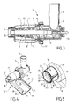
figure 1 illustre un appareil électroménager de préparation culinaire comportant un accessoire de préparation culinaire formant un dispositif de pressage d'aliments selon l'invention, - la
figure 2 est une vue schématique en éclaté de l'accessoire de préparation culinaire illustré sur lafigure 1 , - la
figure 3 est une vue en coupe longitudinale de l'accessoire de préparation culinaire illustré sur lesfigures 1 et 2 , - la
figure 4 est une vue en perspective de l'accessoire de préparation culinaire illustré sur lesfigures 1 à 3 , - la
figure 5 est une vue agrandie d'une partie de lafigure 4 .
- the
figure 1 illustrates an electrical household appliance for culinary preparation comprising a food preparation accessory forming a food pressing device according to the invention, - the
figure 2 is an exploded schematic view of the food preparation accessory shown on thefigure 1 , - the
figure 3 is a longitudinal sectional view of the food preparation accessory illustrated on theFigures 1 and 2 , - the
figure 4 is a perspective view of the food preparation accessory shown on theFigures 1 to 3 , - the
figure 5 is an enlarged view of some of thefigure 4 .
L'appareil électroménager de préparation culinaire illustré sur la
L'accessoire de préparation culinaire 2 comporte une partie rotative 3 susceptible d'être entrainée en rotation par le boîtier moteur 1, mieux visible sur la
L'accessoire de préparation culinaire 2 forme un dispositif de pressage d'aliments pour extraire une partie liquide ou semi-liquide desdits aliments. A cet effet la partie rotative 3 comprend une vis de pressage 4. Dans l'exemple de réalisation illustré sur les figures, la vis de pressage 4 présente un axe de rotation sensiblement horizontal lorsque l'accessoire de préparation culinaire 2 est monté sur le boîtier moteur 1.The
Tel que mieux visible sur la
Dans l'exemple de réalisation illustré sur les figures, le conduit 5 comprend un corps tubulaire 9 dans lequel est ménagé l'ouverture d'admission d'aliments 6, et une partie tubulaire filtrante 10 dans laquelle sont ménagées la ou les zones de filtration 7. La partie tubulaire filtrante 10 est montée amovible par rapport au corps tubulaire 9, par exemple au moyen d'un écrou 11 vissé sur le corps tubulaire 9. A cet effet le corps tubulaire 9 porte des filets extérieurs 12. La partie tubulaire filtrante 10 est tronconique.In the embodiment illustrated in the figures, the
Le conduit 5 porte un axe d'entrainement 13 sur lequel est montée la vis de pressage 4. Plus particulièrement dans l'exemple de réalisation illustré sur les figures, l'axe d'entraînement 13 est monté amovible par rapport au corps tubulaire 9. La partie rotative 3 de l'accessoire de préparation culinaire 2 comprend aussi l'axe d'entrainement 13.The
Selon une forme de réalisation avantageuse, la partie tubulaire filtrante 10 comporte un bati 14 surmoulé autour de la ou des zones de filtration 7. Le bati 14 présente deux extrémités tubulaires 15, 16 reliées par au moins un montant 17. L'extrémité tubulaire 16 adjacente au corps tubulaire 9 porte l'écrou 11.According to an advantageous embodiment, the filtering
Une extrémité libre 18 du conduit 5 forme une sortie à déchets et/ou résidus solides issus de la vis de pressage 4. L'extrémité libre 18 forme une collerette crantée 19, mieux visible sur la
Un organe de déversement latéral 8, mieux visible sur les
Selon la forme de réalisation préférée illustrée sur les figures, des crans 21 sont ménagés sur une extrémité libre 18 du conduit 5. Plus particulièrement, la partie tubulaire filtrante 10 présente au moins une portion de collerette crantée 19 formant une série de crans 21. Par ailleurs, des ergots 31 sont ménagés à l'intérieur d'une couronne fendue 32 de l'organe de déversement latéral 8. Les ergots 31 sont ainsi issus de plusieurs languettes 33 élastiquement déformables.According to the preferred embodiment illustrated in the figures,
Dans l'exemple de réalisation illustré sur les figures, la couronne fendue 32 comporte quatre languettes 33 présentant des zones internes crantées formant les ergots 31, le quatrième volet étant dépourvu de zone interne crantée.In the embodiment shown in the figures, the
De préférence le nombre de crans 21 est supérieur ou égal au nombre d'ergots 31. Ainsi pour chaque position stable de l'organe de déversement latéral chaque ergot 31 peut être logé dans l'un des crans 21.Preferably the number of
Ainsi dans l'exemple de réalisation illustré sur les figures, l'organe de déversement latéral 8 comporte au moins un ergot 31, issu d'une languette 33 élastiquement déformable, qui est susceptible d'être engagé successivement dans au moins deux crans 21 du conduit 5, lorsque l'organe de déversement latéral 8 est pivoté par rapport au conduit 5.Thus, in the exemplary embodiment illustrated in the figures, the
De ce fait, le conduit 5 comporte au moins une conformation de retenue 20 prévue pour retenir au moins deux conformations d'accrochage 30 de l'organe de déversement latéral 8, de sorte que le conduit 5 peut porter l'organe de déversement latéral 8 selon au moins deux positions d'écoulement distinctes.As a result, the
Mais encore, dans l'exemple de réalisation illustré sur les figures, l'organe de déversement latéral 8 comporte au moins deux ergots 31 issus d'au moins une languette 33 élastiquement déformable, qui sont susceptibles d'être engagés dans au moins un cran 21, lorsque l'organe de déversement latéral 8 est pivoté par rapport au conduit 5.But still, in the embodiment illustrated in the figures, the
De ce fait, le conduit 5 comporte au moins deux conformations de retenue 20 prévues pour retenir au moins une conformation d'accrochage 30 de l'organe de déversement latéral 8, de sorte que le conduit 5 peut porter l'organe de déversement latéral 8 selon au moins deux positions d'écoulement distinctes.As a result, the
L'organe de déversement latéral 8 comporte une partie tubulaire 23 entourant la ou les zones de filtration 7 du conduit 5. Plus particulièrement, la partie tubulaire 23 de l'organe de déversement latéral 8 entoure la partie tubulaire filtrante 10 et s'étend autour des extrémités tubulaires 15, 16 de la partie filtrante 10.The
L'organe de déversement latéral 8 est guidé en rotation sur le conduit 5. Plus particulièrement, l'organe de déversement latéral 8 est guidé en rotation sur la partie tubulaire filtrante 10. A cet effet, les extrémités tubulaires 15, 16 de la partie filtrante 10 forment des moyens de guidage en rotation de la partie tubulaire 23 de l'organe de déversement latéral 8. De préférence, l'axe de pivotement de l'organe de déversement latéral 8 est confondu avec l'axe de rotation de la vis de pressage 4.The
De préférence, l'organe de déversement latéral 8 est monté amovible sur le conduit 5.Preferably, the
La partie tubulaire 23 est prolongée par un déversoir 24 présentant un fond 25 raccordé à deux parois latérales 26, 27. Chaque paroi latérale 26, 27 est prolongée par une paroi supérieure interne 28, 29 s'étendant au dessus du fond 25 en ménageant une ouverture supérieure 35.The
L'appareil électroménager de préparation culinaire et le dispositif de pressage selon l'invention fonctionnent et s'utilisent de la manière suivante.The electrical household appliance and the pressing device according to the invention operate and are used in the following manner.
L'utilisateur monte l'accessoire de préparation culinaire 2 sur le boîtier moteur 1 et positionne l'organe de déversement latéral 8 selon l'inclinaison souhaitée en pivotant l'organe de déversement latéral 8 par rapport au conduit 5.The user mounts the
La couronne fendue 32 de l'organe de déversement latéral 8 forme une série de clips souples ou languettes 33 élastiquement déformables portant les ergots 31, qui peuvent se déformer pour que les ergots 31 passent les sommets des crans 21 du conduit 5, tout en maintenant l'organe de déversement latéral 8 en position lorsque les ergots 31 sont disposés à l'intérieur des crans 21, formant des conformations d'accrochage 30 retenues par des conformations de retenue 20. L'organe de déversement latéral 8 peut ainsi occuper plusieurs positions angulaires stables par rapport au conduit 5, ces positions présentant des pentes d'écoulement différentes.The
Les ergots 31 issus de languettes 33 élastiquement déformables peuvent ainsi passer d'un cran 21 à un autre cran 21 par simple rotation de l'organe de déversement latéral 8 par rapport au conduit 5, tout en assurant une retenue de l'organe de déversement latéral 8 dans des positions déterminées. Dans les positions stables de l'organe de déversement latéral 8, chaque ergot 31 est engagé dans un des crans 21, de sorte que la déformation élastique des languettes 33 peut être minimisée, voire annulée.The
Le conduit 5 comporte ainsi des moyens de retenue prévus pour retenir des moyens d'accrochage de l'organe de déversement latéral, de sorte que le conduit 5 peut porter l'organe de déversement latéral 8 selon au moins deux positions d'écoulement distinctes.The
De plus, si désiré, le ou les crans 21 et le ou les ergots 31 peuvent être agencés de sorte que l'extrémité libre du déversoir 24 puisse être relevée au dessus de l'extrémité du déversoir 24 reliée à la partie tubulaire 23. L'écoulement hors de l'organe de déversement latéral 8 est stoppé. La ou au moins l'une des conformations de retenue 20 est alors susceptible de retenir la ou au moins l'une des conformations d'accrochage 30 de sorte que le conduit 5 porte l'organe de déversement latéral 8 selon une position de retenue dans laquelle l'écoulement hors de l'organe de déversement latéral 8 est empêché.In addition, if desired, the notch (s) 21 and the lug (s) 31 may be arranged so that the free end of the
La forme fermée de l'organe de déversement latéral 8 permet à l'utilisateur de ne pas recevoir les éventuelles projections de jus ou de coulis lors de la réalisation.The closed shape of the
A titre de variante, le conduit 5 pourrait présenter au moins un cran 21 prévu pour recevoir plusieurs ergots 31 de l'organe de déversement latéral 8, ou l'organe de déversement latéral 8 pourrait présenter au moins un ergot 31 prévu pour être engagé dans plusieurs crans 21 du conduit 5.Alternatively, the
A titre de variante, la ou les conformations de retenue 20 du conduit 5 ne sont pas nécessairement formées par un ou plusieurs crans 21, et la ou les conformations d'accrochage 30 de l'organe de déversement latéral 8 ne sont pas nécessairement formés par un ou plusieurs ergots 31. Notamment, la ou les conformations de retenue 20 du conduit 5 pourraient être formées par un ou plusieurs ergots, et la ou les conformations d'accrochage 30 de l'organe de déversement latéral 8 pourraient être formées par un ou plusieurs crans 21. Le conduit 5 comporte alors au moins un ergot 31 susceptible d'être engagé dans au moins deux crans 21 de l'organe de déversement latéral 8 et/ou au moins deux ergots 31 susceptibles d'être engagés dans au moins un cran 21 de l'organe de déversement latéral 8. Si désiré, le ou les crans 21 peuvent notamment être ménagés à l'intérieur d'une extrémité libre de l'organe de déversement latéral 8, le ou les ergots 31 pouvant alors être ménagés sur une couronne fendue du conduit 5.Alternatively, the retaining
A titre de variante, le ou les ergots 31 ne sont pas nécessairement issus d'une ou plusieurs languettes 33 élastiquement déformables. L'organe de déversement latéral 8 pourrait alors être déplacé en translation par rapport au conduit 5, pour dégager le ou les ergots 31 de l'un ou de plusieurs des crans 21, faire pivoter l'organe de déversement latéral 8 par rapport au conduit 5, et engager le ou l'un des ergots 31 dans au moins un autre cran 21.As a variant, the lug (s) 31 are not necessarily derived from a or
A titre de variante, la partie tubulaire filtrante 10 n'est pas nécessairement montée amovible par rapport au corps tubulaire 9 au moyen de l'écrou 11, mais pourrait par exemple être assemblée par vissage.Alternatively, the filtering
A titre de variante, le conduit 5 ne comporte pas nécessairement une partie tubulaire filtrante 10 montée amovible par rapport à un corps tubulaire 9. En alternative, l'ouverture d'admission 6 pourrait notamment être ménagée dans la partie tubulaire filtrante 10.As a variant, the
A titre de variante, la vis de pressage 4 n'est pas nécessairement entrainée par un axe d'entraînement 13 monté dans le conduit 5. Notamment, la vis de pressage 4 pourrait être entrainée par le boîtier moteur 1 ou par une manivelle montée sur l'une des extrémités de la vis de pressage 4.Alternatively, the
A titre de variante, la partie tubulaire 23 de l'organe de déversement latéral 8 ne présente pas nécessairement une géométrie de révolution en dehors des zones de guidage en rotation sur le conduit 5.As a variant, the
La présente invention n'est nullement limitée à l'exemple de réalisation décrit et à ses variantes, mais englobe de nombreuses modifications dans le cadre des revendications.The present invention is not limited to the embodiment described and its variants, but encompasses many modifications within the scope of the claims.
Claims (15)
Applications Claiming Priority (1)
| Application Number | Priority Date | Filing Date | Title |
|---|---|---|---|
| FR1154194A FR2974991B1 (en) | 2011-05-13 | 2011-05-13 | FOOD PRESSING DEVICE HAVING ADJUSTABLE INCLINATION SPILLING DEVICE |
Publications (2)
| Publication Number | Publication Date |
|---|---|
| EP2522259A1 true EP2522259A1 (en) | 2012-11-14 |
| EP2522259B1 EP2522259B1 (en) | 2013-12-25 |
Family
ID=44310214
Family Applications (1)
| Application Number | Title | Priority Date | Filing Date |
|---|---|---|---|
| EP20120166518 Active EP2522259B1 (en) | 2011-05-13 | 2012-05-03 | Food-pressing device comprising a pouring member with adjustable inclination |
Country Status (3)
| Country | Link |
|---|---|
| EP (1) | EP2522259B1 (en) |
| CN (1) | CN202775774U (en) |
| FR (1) | FR2974991B1 (en) |
Cited By (5)
| Publication number | Priority date | Publication date | Assignee | Title |
|---|---|---|---|---|
| EP2845526A1 (en) * | 2013-09-09 | 2015-03-11 | Seb S.A. | Food preparation device for extracting juice and/or coulis and controlling the flow thereof |
| EP2845525A1 (en) * | 2013-09-09 | 2015-03-11 | Seb S.A. | Food preparation device for extracting juice and/or coulis |
| WO2015033056A1 (en) * | 2013-09-09 | 2015-03-12 | Seb S.A. | Method for extracting juice and/or coulis, and device implementing such a method |
| WO2015139052A1 (en) * | 2014-03-14 | 2015-09-17 | Several Gardens Farm | Two stage cold press juicer |
| WO2018073195A1 (en) * | 2016-10-17 | 2018-04-26 | Koninklijke Philips N.V. | Juice extractor |
Families Citing this family (2)
| Publication number | Priority date | Publication date | Assignee | Title |
|---|---|---|---|---|
| CN105054754B (en) * | 2015-08-24 | 2017-04-12 | 李锦坚 | Tomato juicing machine |
| CN108877054B (en) * | 2018-08-14 | 2024-01-05 | 深圳市道中创新科技有限公司 | Fruit juice machine |
Citations (3)
| Publication number | Priority date | Publication date | Assignee | Title |
|---|---|---|---|---|
| US1615734A (en) | 1925-11-14 | 1927-01-25 | Alfisi Giuseppe | Fruit and vegetable squeezer |
| US1750764A (en) * | 1926-12-17 | 1930-03-18 | American Utensil Company | Separator |
| FR2775176A1 (en) * | 1998-02-24 | 1999-08-27 | Georges Gallo | Table top grape press for juice extraction |
-
2011
- 2011-05-13 FR FR1154194A patent/FR2974991B1/en not_active Expired - Fee Related
-
2012
- 2012-05-03 EP EP20120166518 patent/EP2522259B1/en active Active
- 2012-05-11 CN CN 201220212854 patent/CN202775774U/en not_active Expired - Lifetime
Patent Citations (3)
| Publication number | Priority date | Publication date | Assignee | Title |
|---|---|---|---|---|
| US1615734A (en) | 1925-11-14 | 1927-01-25 | Alfisi Giuseppe | Fruit and vegetable squeezer |
| US1750764A (en) * | 1926-12-17 | 1930-03-18 | American Utensil Company | Separator |
| FR2775176A1 (en) * | 1998-02-24 | 1999-08-27 | Georges Gallo | Table top grape press for juice extraction |
Cited By (12)
| Publication number | Priority date | Publication date | Assignee | Title |
|---|---|---|---|---|
| EP2845526A1 (en) * | 2013-09-09 | 2015-03-11 | Seb S.A. | Food preparation device for extracting juice and/or coulis and controlling the flow thereof |
| EP2845525A1 (en) * | 2013-09-09 | 2015-03-11 | Seb S.A. | Food preparation device for extracting juice and/or coulis |
| WO2015033056A1 (en) * | 2013-09-09 | 2015-03-12 | Seb S.A. | Method for extracting juice and/or coulis, and device implementing such a method |
| WO2015033055A1 (en) * | 2013-09-09 | 2015-03-12 | Seb S.A. | Device for preparing foodstuffs in order to extract juices and/or coulis |
| WO2015033054A1 (en) * | 2013-09-09 | 2015-03-12 | Seb S.A. | Device for preparing foodstuffs in order to extract juices and/or coulis and control the flow thereof |
| FR3010296A1 (en) * | 2013-09-09 | 2015-03-13 | Seb Sa | FOOD PREPARATION DEVICE FOR EXTRACTING JUICE AND / OR GROUT AND CONTROLLING THEIR FLOW |
| FR3010295A1 (en) * | 2013-09-09 | 2015-03-13 | Seb Sa | PROCESS FOR EXTRACTING JUICE AND / OR GROUT, AND DEVICE USING SUCH A METHOD |
| FR3010294A1 (en) * | 2013-09-09 | 2015-03-13 | Seb Sa | FOOD PREPARATION DEVICE FOR EXTRACTING JUICES AND / OR GROUT |
| WO2015139052A1 (en) * | 2014-03-14 | 2015-09-17 | Several Gardens Farm | Two stage cold press juicer |
| US9763470B2 (en) | 2014-03-14 | 2017-09-19 | Several Gardens Farm | Two stage cold press juicer |
| WO2018073195A1 (en) * | 2016-10-17 | 2018-04-26 | Koninklijke Philips N.V. | Juice extractor |
| RU2728634C1 (en) * | 2016-10-17 | 2020-07-30 | Конинклейке Филипс Н.В. | Juicer |
Also Published As
| Publication number | Publication date |
|---|---|
| FR2974991B1 (en) | 2013-05-31 |
| FR2974991A1 (en) | 2012-11-16 |
| CN202775774U (en) | 2013-03-13 |
| EP2522259B1 (en) | 2013-12-25 |
Similar Documents
| Publication | Publication Date | Title |
|---|---|---|
| EP2522259B1 (en) | Food-pressing device comprising a pouring member with adjustable inclination | |
| EP2637519B1 (en) | Electrical kitchen appliance comprising a pressing screw | |
| EP2060216B1 (en) | Electrical kitchen appliance comprising a support for a mixing element | |
| EP0191161B1 (en) | Electric household apparatus for preparing food like sauces or creams | |
| EP2846664B1 (en) | Rotary working member and electric household food preparation appliance comprising a pressing screw | |
| EP2914148B1 (en) | Electric household appliance for culinary preparation, comprising a pressing screw and at least one filter | |
| EP1900315B1 (en) | Immersed domestic mixer comprising a work tool in the shape of an Archimedes screw | |
| EP3311717A1 (en) | Electrical kitchen appliance comprising an intermediate cover | |
| FR2967035A1 (en) | Electric household appliance for preparation of e.g. sauce, has filtering element separating work chamber into two compartments, and filtering part arranged between pressing screw and evacuation outlet | |
| FR2908621A1 (en) | ROTARY WORKING TOOL FOR CULINARY PREPARATION ELECTRICAL APPLIANCES, ESPECIALLY CONFITURING | |
| EP1529468B1 (en) | Citrus fruit squeezer with pouring device | |
| EP3528677B1 (en) | Electrical household food-preparation appliance comprising a power supply base | |
| EP2845526B1 (en) | Food preparation device for extracting juice and/or coulis and controlling the flow thereof | |
| EP3071077B1 (en) | Household appliance for culinary preparation, comprising a press screw having an axial support | |
| EP3685719B1 (en) | Electrical kitchen appliance comprising an internal container | |
| EP3528678B1 (en) | Electrical household heating food-preparation appliance comprising a steamer basket | |
| EP2949247B1 (en) | Food-preparation device suitable for extracting juice and/or coulis | |
| EP3113656B1 (en) | Device for the preparation of foodstuffs comprising a supply chute receiving an overflow-preventing plunger | |
| EP2785229B1 (en) | Accessory for supporting a motor-driven housing of a kitchen appliance | |
| FR2992541A1 (en) | FOOD CUTTING ELECTRICAL APPLIANCE WITH STORAGE OF FOOD CUTTING ACCESSORIES | |
| FR2886831A1 (en) | Rotary blender for mixing e.g. meat, has cell supplying motor unit which drives S-shaped or pick-shaped agitator, where agitator is in connection with lid so as to mix food in stewpot or permit cooking of meat fixed to pick-shaped agitator | |
| FR3094620A1 (en) | CITRUS PRESS ACCESSORY FOR CULINARY PREPARATION APPLIANCES |
Legal Events
| Date | Code | Title | Description |
|---|---|---|---|
| PUAI | Public reference made under article 153(3) epc to a published international application that has entered the european phase |
Free format text: ORIGINAL CODE: 0009012 |
|
| AK | Designated contracting states |
Kind code of ref document: A1 Designated state(s): AL AT BE BG CH CY CZ DE DK EE ES FI FR GB GR HR HU IE IS IT LI LT LU LV MC MK MT NL NO PL PT RO RS SE SI SK SM TR |
|
| AX | Request for extension of the european patent |
Extension state: BA ME |
|
| 17P | Request for examination filed |
Effective date: 20130507 |
|
| RIC1 | Information provided on ipc code assigned before grant |
Ipc: A47J 19/02 20060101AFI20130527BHEP |
|
| GRAP | Despatch of communication of intention to grant a patent |
Free format text: ORIGINAL CODE: EPIDOSNIGR1 |
|
| INTG | Intention to grant announced |
Effective date: 20130724 |
|
| RIN1 | Information on inventor provided before grant (corrected) |
Inventor name: PEYRAS, LIONEL Inventor name: SMIT, ROBERT Inventor name: SENTAGNES, CLEMENCE |
|
| GRAS | Grant fee paid |
Free format text: ORIGINAL CODE: EPIDOSNIGR3 |
|
| GRAA | (expected) grant |
Free format text: ORIGINAL CODE: 0009210 |
|
| AK | Designated contracting states |
Kind code of ref document: B1 Designated state(s): AL AT BE BG CH CY CZ DE DK EE ES FI FR GB GR HR HU IE IS IT LI LT LU LV MC MK MT NL NO PL PT RO RS SE SI SK SM TR |
|
| REG | Reference to a national code |
Ref country code: GB Ref legal event code: FG4D Free format text: NOT ENGLISH |
|
| REG | Reference to a national code |
Ref country code: CH Ref legal event code: EP |
|
| REG | Reference to a national code |
Ref country code: AT Ref legal event code: REF Ref document number: 646105 Country of ref document: AT Kind code of ref document: T Effective date: 20140115 |
|
| REG | Reference to a national code |
Ref country code: IE Ref legal event code: FG4D Free format text: LANGUAGE OF EP DOCUMENT: FRENCH |
|
| REG | Reference to a national code |
Ref country code: DE Ref legal event code: R096 Ref document number: 602012000702 Country of ref document: DE Effective date: 20140213 |
|
| PG25 | Lapsed in a contracting state [announced via postgrant information from national office to epo] |
Ref country code: FI Free format text: LAPSE BECAUSE OF FAILURE TO SUBMIT A TRANSLATION OF THE DESCRIPTION OR TO PAY THE FEE WITHIN THE PRESCRIBED TIME-LIMIT Effective date: 20131225 Ref country code: SE Free format text: LAPSE BECAUSE OF FAILURE TO SUBMIT A TRANSLATION OF THE DESCRIPTION OR TO PAY THE FEE WITHIN THE PRESCRIBED TIME-LIMIT Effective date: 20131225 Ref country code: LT Free format text: LAPSE BECAUSE OF FAILURE TO SUBMIT A TRANSLATION OF THE DESCRIPTION OR TO PAY THE FEE WITHIN THE PRESCRIBED TIME-LIMIT Effective date: 20131225 Ref country code: NO Free format text: LAPSE BECAUSE OF FAILURE TO SUBMIT A TRANSLATION OF THE DESCRIPTION OR TO PAY THE FEE WITHIN THE PRESCRIBED TIME-LIMIT Effective date: 20140325 Ref country code: HR Free format text: LAPSE BECAUSE OF FAILURE TO SUBMIT A TRANSLATION OF THE DESCRIPTION OR TO PAY THE FEE WITHIN THE PRESCRIBED TIME-LIMIT Effective date: 20131225 |
|
| REG | Reference to a national code |
Ref country code: NL Ref legal event code: VDEP Effective date: 20131225 |
|
| REG | Reference to a national code |
Ref country code: AT Ref legal event code: MK05 Ref document number: 646105 Country of ref document: AT Kind code of ref document: T Effective date: 20131225 |
|
| REG | Reference to a national code |
Ref country code: LT Ref legal event code: MG4D |
|
| PG25 | Lapsed in a contracting state [announced via postgrant information from national office to epo] |
Ref country code: LV Free format text: LAPSE BECAUSE OF FAILURE TO SUBMIT A TRANSLATION OF THE DESCRIPTION OR TO PAY THE FEE WITHIN THE PRESCRIBED TIME-LIMIT Effective date: 20131225 Ref country code: RS Free format text: LAPSE BECAUSE OF FAILURE TO SUBMIT A TRANSLATION OF THE DESCRIPTION OR TO PAY THE FEE WITHIN THE PRESCRIBED TIME-LIMIT Effective date: 20131225 |
|
| PG25 | Lapsed in a contracting state [announced via postgrant information from national office to epo] |
Ref country code: IS Free format text: LAPSE BECAUSE OF FAILURE TO SUBMIT A TRANSLATION OF THE DESCRIPTION OR TO PAY THE FEE WITHIN THE PRESCRIBED TIME-LIMIT Effective date: 20140425 Ref country code: EE Free format text: LAPSE BECAUSE OF FAILURE TO SUBMIT A TRANSLATION OF THE DESCRIPTION OR TO PAY THE FEE WITHIN THE PRESCRIBED TIME-LIMIT Effective date: 20131225 |
|
| PG25 | Lapsed in a contracting state [announced via postgrant information from national office to epo] |
Ref country code: PT Free format text: LAPSE BECAUSE OF FAILURE TO SUBMIT A TRANSLATION OF THE DESCRIPTION OR TO PAY THE FEE WITHIN THE PRESCRIBED TIME-LIMIT Effective date: 20140428 Ref country code: AT Free format text: LAPSE BECAUSE OF FAILURE TO SUBMIT A TRANSLATION OF THE DESCRIPTION OR TO PAY THE FEE WITHIN THE PRESCRIBED TIME-LIMIT Effective date: 20131225 Ref country code: CZ Free format text: LAPSE BECAUSE OF FAILURE TO SUBMIT A TRANSLATION OF THE DESCRIPTION OR TO PAY THE FEE WITHIN THE PRESCRIBED TIME-LIMIT Effective date: 20131225 Ref country code: SK Free format text: LAPSE BECAUSE OF FAILURE TO SUBMIT A TRANSLATION OF THE DESCRIPTION OR TO PAY THE FEE WITHIN THE PRESCRIBED TIME-LIMIT Effective date: 20131225 Ref country code: CY Free format text: LAPSE BECAUSE OF FAILURE TO SUBMIT A TRANSLATION OF THE DESCRIPTION OR TO PAY THE FEE WITHIN THE PRESCRIBED TIME-LIMIT Effective date: 20131225 Ref country code: NL Free format text: LAPSE BECAUSE OF FAILURE TO SUBMIT A TRANSLATION OF THE DESCRIPTION OR TO PAY THE FEE WITHIN THE PRESCRIBED TIME-LIMIT Effective date: 20131225 Ref country code: ES Free format text: LAPSE BECAUSE OF FAILURE TO SUBMIT A TRANSLATION OF THE DESCRIPTION OR TO PAY THE FEE WITHIN THE PRESCRIBED TIME-LIMIT Effective date: 20131225 Ref country code: RO Free format text: LAPSE BECAUSE OF FAILURE TO SUBMIT A TRANSLATION OF THE DESCRIPTION OR TO PAY THE FEE WITHIN THE PRESCRIBED TIME-LIMIT Effective date: 20131225 |
|
| REG | Reference to a national code |
Ref country code: DE Ref legal event code: R097 Ref document number: 602012000702 Country of ref document: DE |
|
| PG25 | Lapsed in a contracting state [announced via postgrant information from national office to epo] |
Ref country code: DK Free format text: LAPSE BECAUSE OF FAILURE TO SUBMIT A TRANSLATION OF THE DESCRIPTION OR TO PAY THE FEE WITHIN THE PRESCRIBED TIME-LIMIT Effective date: 20131225 |
|
| PLBE | No opposition filed within time limit |
Free format text: ORIGINAL CODE: 0009261 |
|
| STAA | Information on the status of an ep patent application or granted ep patent |
Free format text: STATUS: NO OPPOSITION FILED WITHIN TIME LIMIT |
|
| PG25 | Lapsed in a contracting state [announced via postgrant information from national office to epo] |
Ref country code: PL Free format text: LAPSE BECAUSE OF FAILURE TO SUBMIT A TRANSLATION OF THE DESCRIPTION OR TO PAY THE FEE WITHIN THE PRESCRIBED TIME-LIMIT Effective date: 20131225 |
|
| REG | Reference to a national code |
Ref country code: DE Ref legal event code: R119 Ref document number: 602012000702 Country of ref document: DE |
|
| 26N | No opposition filed |
Effective date: 20140926 |
|
| PG25 | Lapsed in a contracting state [announced via postgrant information from national office to epo] |
Ref country code: LU Free format text: LAPSE BECAUSE OF FAILURE TO SUBMIT A TRANSLATION OF THE DESCRIPTION OR TO PAY THE FEE WITHIN THE PRESCRIBED TIME-LIMIT Effective date: 20140503 |
|
| REG | Reference to a national code |
Ref country code: DE Ref legal event code: R097 Ref document number: 602012000702 Country of ref document: DE Effective date: 20140926 |
|
| PG25 | Lapsed in a contracting state [announced via postgrant information from national office to epo] |
Ref country code: MC Free format text: LAPSE BECAUSE OF FAILURE TO SUBMIT A TRANSLATION OF THE DESCRIPTION OR TO PAY THE FEE WITHIN THE PRESCRIBED TIME-LIMIT Effective date: 20131225 |
|
| REG | Reference to a national code |
Ref country code: IE Ref legal event code: MM4A |
|
| REG | Reference to a national code |
Ref country code: DE Ref legal event code: R119 Ref document number: 602012000702 Country of ref document: DE Effective date: 20141202 |
|
| PG25 | Lapsed in a contracting state [announced via postgrant information from national office to epo] |
Ref country code: IE Free format text: LAPSE BECAUSE OF NON-PAYMENT OF DUE FEES Effective date: 20140503 Ref country code: DE Free format text: LAPSE BECAUSE OF NON-PAYMENT OF DUE FEES Effective date: 20141202 |
|
| PG25 | Lapsed in a contracting state [announced via postgrant information from national office to epo] |
Ref country code: SI Free format text: LAPSE BECAUSE OF FAILURE TO SUBMIT A TRANSLATION OF THE DESCRIPTION OR TO PAY THE FEE WITHIN THE PRESCRIBED TIME-LIMIT Effective date: 20131225 |
|
| REG | Reference to a national code |
Ref country code: CH Ref legal event code: PL |
|
| PG25 | Lapsed in a contracting state [announced via postgrant information from national office to epo] |
Ref country code: LI Free format text: LAPSE BECAUSE OF NON-PAYMENT OF DUE FEES Effective date: 20150531 Ref country code: CH Free format text: LAPSE BECAUSE OF NON-PAYMENT OF DUE FEES Effective date: 20150531 |
|
| PG25 | Lapsed in a contracting state [announced via postgrant information from national office to epo] |
Ref country code: MT Free format text: LAPSE BECAUSE OF FAILURE TO SUBMIT A TRANSLATION OF THE DESCRIPTION OR TO PAY THE FEE WITHIN THE PRESCRIBED TIME-LIMIT Effective date: 20131225 |
|
| PG25 | Lapsed in a contracting state [announced via postgrant information from national office to epo] |
Ref country code: SM Free format text: LAPSE BECAUSE OF FAILURE TO SUBMIT A TRANSLATION OF THE DESCRIPTION OR TO PAY THE FEE WITHIN THE PRESCRIBED TIME-LIMIT Effective date: 20131225 |
|
| REG | Reference to a national code |
Ref country code: FR Ref legal event code: PLFP Year of fee payment: 5 |
|
| PG25 | Lapsed in a contracting state [announced via postgrant information from national office to epo] |
Ref country code: BG Free format text: LAPSE BECAUSE OF FAILURE TO SUBMIT A TRANSLATION OF THE DESCRIPTION OR TO PAY THE FEE WITHIN THE PRESCRIBED TIME-LIMIT Effective date: 20131225 Ref country code: GR Free format text: LAPSE BECAUSE OF FAILURE TO SUBMIT A TRANSLATION OF THE DESCRIPTION OR TO PAY THE FEE WITHIN THE PRESCRIBED TIME-LIMIT Effective date: 20140326 |
|
| PG25 | Lapsed in a contracting state [announced via postgrant information from national office to epo] |
Ref country code: BE Free format text: LAPSE BECAUSE OF FAILURE TO SUBMIT A TRANSLATION OF THE DESCRIPTION OR TO PAY THE FEE WITHIN THE PRESCRIBED TIME-LIMIT Effective date: 20140531 Ref country code: TR Free format text: LAPSE BECAUSE OF FAILURE TO SUBMIT A TRANSLATION OF THE DESCRIPTION OR TO PAY THE FEE WITHIN THE PRESCRIBED TIME-LIMIT Effective date: 20131225 Ref country code: HU Free format text: LAPSE BECAUSE OF FAILURE TO SUBMIT A TRANSLATION OF THE DESCRIPTION OR TO PAY THE FEE WITHIN THE PRESCRIBED TIME-LIMIT; INVALID AB INITIO Effective date: 20120503 |
|
| GBPC | Gb: european patent ceased through non-payment of renewal fee |
Effective date: 20160503 |
|
| REG | Reference to a national code |
Ref country code: FR Ref legal event code: PLFP Year of fee payment: 6 |
|
| PG25 | Lapsed in a contracting state [announced via postgrant information from national office to epo] |
Ref country code: GB Free format text: LAPSE BECAUSE OF NON-PAYMENT OF DUE FEES Effective date: 20160503 |
|
| REG | Reference to a national code |
Ref country code: FR Ref legal event code: CA Effective date: 20170518 |
|
| REG | Reference to a national code |
Ref country code: FR Ref legal event code: PLFP Year of fee payment: 7 |
|
| PG25 | Lapsed in a contracting state [announced via postgrant information from national office to epo] |
Ref country code: MK Free format text: LAPSE BECAUSE OF FAILURE TO SUBMIT A TRANSLATION OF THE DESCRIPTION OR TO PAY THE FEE WITHIN THE PRESCRIBED TIME-LIMIT Effective date: 20131225 |
|
| PG25 | Lapsed in a contracting state [announced via postgrant information from national office to epo] |
Ref country code: AL Free format text: LAPSE BECAUSE OF FAILURE TO SUBMIT A TRANSLATION OF THE DESCRIPTION OR TO PAY THE FEE WITHIN THE PRESCRIBED TIME-LIMIT Effective date: 20131225 |
|
| PGFP | Annual fee paid to national office [announced via postgrant information from national office to epo] |
Ref country code: IT Payment date: 20230517 Year of fee payment: 12 Ref country code: FR Payment date: 20230523 Year of fee payment: 12 |