EP2522025B1 - Systeme d'alimentation par induction et meuble pour un tel systeme - Google Patents
Systeme d'alimentation par induction et meuble pour un tel systeme Download PDFInfo
- Publication number
- EP2522025B1 EP2522025B1 EP11705002.1A EP11705002A EP2522025B1 EP 2522025 B1 EP2522025 B1 EP 2522025B1 EP 11705002 A EP11705002 A EP 11705002A EP 2522025 B1 EP2522025 B1 EP 2522025B1
- Authority
- EP
- European Patent Office
- Prior art keywords
- furniture
- piece
- wall
- appliance
- inductor
- Prior art date
- Legal status (The legal status is an assumption and is not a legal conclusion. Google has not performed a legal analysis and makes no representation as to the accuracy of the status listed.)
- Active
Links
Images




Classifications
-
- H—ELECTRICITY
- H01—ELECTRIC ELEMENTS
- H01F—MAGNETS; INDUCTANCES; TRANSFORMERS; SELECTION OF MATERIALS FOR THEIR MAGNETIC PROPERTIES
- H01F38/00—Adaptations of transformers or inductances for specific applications or functions
- H01F38/14—Inductive couplings
-
- H—ELECTRICITY
- H05—ELECTRIC TECHNIQUES NOT OTHERWISE PROVIDED FOR
- H05B—ELECTRIC HEATING; ELECTRIC LIGHT SOURCES NOT OTHERWISE PROVIDED FOR; CIRCUIT ARRANGEMENTS FOR ELECTRIC LIGHT SOURCES, IN GENERAL
- H05B45/00—Circuit arrangements for operating light-emitting diodes [LED]
- H05B45/20—Controlling the colour of the light
-
- H—ELECTRICITY
- H05—ELECTRIC TECHNIQUES NOT OTHERWISE PROVIDED FOR
- H05B—ELECTRIC HEATING; ELECTRIC LIGHT SOURCES NOT OTHERWISE PROVIDED FOR; CIRCUIT ARRANGEMENTS FOR ELECTRIC LIGHT SOURCES, IN GENERAL
- H05B45/00—Circuit arrangements for operating light-emitting diodes [LED]
- H05B45/30—Driver circuits
- H05B45/37—Converter circuits
- H05B45/3725—Switched mode power supply [SMPS]
- H05B45/39—Circuits containing inverter bridges
-
- H—ELECTRICITY
- H05—ELECTRIC TECHNIQUES NOT OTHERWISE PROVIDED FOR
- H05B—ELECTRIC HEATING; ELECTRIC LIGHT SOURCES NOT OTHERWISE PROVIDED FOR; CIRCUIT ARRANGEMENTS FOR ELECTRIC LIGHT SOURCES, IN GENERAL
- H05B47/00—Circuit arrangements for operating light sources in general, i.e. where the type of light source is not relevant
- H05B47/10—Controlling the light source
- H05B47/105—Controlling the light source in response to determined parameters
- H05B47/115—Controlling the light source in response to determined parameters by determining the presence or movement of objects or living beings
-
- F—MECHANICAL ENGINEERING; LIGHTING; HEATING; WEAPONS; BLASTING
- F21—LIGHTING
- F21W—INDEXING SCHEME ASSOCIATED WITH SUBCLASSES F21K, F21L, F21S and F21V, RELATING TO USES OR APPLICATIONS OF LIGHTING DEVICES OR SYSTEMS
- F21W2131/00—Use or application of lighting devices or systems not provided for in codes F21W2102/00-F21W2121/00
- F21W2131/30—Lighting for domestic or personal use
- F21W2131/301—Lighting for domestic or personal use for furniture
-
- F—MECHANICAL ENGINEERING; LIGHTING; HEATING; WEAPONS; BLASTING
- F21—LIGHTING
- F21Y—INDEXING SCHEME ASSOCIATED WITH SUBCLASSES F21K, F21L, F21S and F21V, RELATING TO THE FORM OR THE KIND OF THE LIGHT SOURCES OR OF THE COLOUR OF THE LIGHT EMITTED
- F21Y2115/00—Light-generating elements of semiconductor light sources
- F21Y2115/10—Light-emitting diodes [LED]
-
- Y—GENERAL TAGGING OF NEW TECHNOLOGICAL DEVELOPMENTS; GENERAL TAGGING OF CROSS-SECTIONAL TECHNOLOGIES SPANNING OVER SEVERAL SECTIONS OF THE IPC; TECHNICAL SUBJECTS COVERED BY FORMER USPC CROSS-REFERENCE ART COLLECTIONS [XRACs] AND DIGESTS
- Y02—TECHNOLOGIES OR APPLICATIONS FOR MITIGATION OR ADAPTATION AGAINST CLIMATE CHANGE
- Y02B—CLIMATE CHANGE MITIGATION TECHNOLOGIES RELATED TO BUILDINGS, e.g. HOUSING, HOUSE APPLIANCES OR RELATED END-USER APPLICATIONS
- Y02B20/00—Energy efficient lighting technologies, e.g. halogen lamps or gas discharge lamps
- Y02B20/40—Control techniques providing energy savings, e.g. smart controller or presence detection
Definitions
- the present invention relates to an induction power supply system for a device, in particular a power supply for a light-emitting diode (LED) lighting device, and to a piece of furniture or a construction equipped for the induction supply of such a device.
- a device in particular a power supply for a light-emitting diode (LED) lighting device
- LED light-emitting diode
- the patent US-5264997 describes a light-emitting diode (LED) lighting device powered by induction.
- the apparatus comprises a housing containing a printed circuit; a secondary winding formed of a wire wound in a spiral is provided on one side of the printed circuit, and the LEDs connected to the secondary winding are arranged on the other side of the printed circuit.
- the housing is secured to a socket having a primary winding forming an inductor for the secondary winding.
- the case consists of an opaque bottom and a transparent optic secured by adhesive.
- This patent proposes to connect several sets of LEDs in parallel to the secondary winding, the LEDs of each set being connected in series.
- Such a lighting device has a low efficiency and produces a luminous flux whose intensity and color are not controlled, due in particular to the disparity of the characteristics of LEDs of a given model.
- the inductors fitted to the base and the lighting modules are also produced in the form of printed circuit tracks.
- FR2695285A3 describes a piece of furniture or construction according to the preamble of claim 1.
- An object of the invention is to propose an induction supply system which is improved and / or which remedies, at least in part, the shortcomings or disadvantages of known induction supply systems.
- An objective of the invention is to provide a piece of furniture or a construction equipped for the induction supply of a device having a consumption of at least one or more ten (s) Watt.
- an appliance is supplied by induction arranged on (or against) a first face - or external face - of a wall of a piece of furniture or of a construction, through this wall, by the '' through an inductor arranged against (or along) a second face - or internal face - of the wall and traversed by an alternating current, the inductor being integral with the piece of furniture - respectively of the construction - and essentially consisting of thick conductors, of substantially rectangular section, forming a spiral, and coated with - or embedded in - an electrically insulating material.
- a piece of furniture or a construction according to claim 1 there is provided a piece of furniture or a construction according to claim 1, and a manufacturing method according to claim 15.
- the invention applies to furniture and constructions whose wall comprises a mixture of plastic and mineral particles.
- the wall consists essentially of a mixture of plastic and mineral particles, in particular of a mixture of acrylic resin and quartz or alumina hydrate.
- the thickness of the wall is preferably in a range from about 1 millimeter to about 50 millimeters.
- the thickness of the conductor (s) forming the inductance is generally at least equal to 200 microns, preferably situated in a range going from approximately 0.2 millimeter up to approximately 1 millimeter, in particular of the order of 0.3 to 0.6 millimeter.
- the wall may extend substantially horizontally or substantially vertically.
- the piece of furniture or the construction may comprise a magnetic structure arranged substantially flush with the external face of the wall, and adapted to cause, when it is placed in the magnetic field of a magnet secured to the device to be supplied, a force d mutual attraction between the device and the furniture or construction, which is sufficient to keep the device integral with the wall.
- the inductance can be secured to the furniture or to the construction by gluing in particular.
- the generator may include an "H” bridge in which the inductor is connected in series with a capacity, and a control unit arranged to drive the switches of the "H" bridge.
- the generator may include a radio transmitter connected to the control unit and allowing the control unit to receive control data from the bridge.
- the supply system may include a device for remote control of the generator and / or of the device to be supplied, which includes a sensor sensitive to the incident light flux (ambient), and optionally includes several sensors respectively sensitive to different spectral bands of the incident light flux (ambient).
- a device for remote control of the generator and / or of the device to be supplied which includes a sensor sensitive to the incident light flux (ambient), and optionally includes several sensors respectively sensitive to different spectral bands of the incident light flux (ambient).
- the remote control device can include a motion sensor integral with the remote control device housing, which makes it possible to detect movements of the remote control device and to modify the control signals delivered to the generator and / or the signal accordingly. device to be powered.
- the inductor can be simply manufactured with a shape and dimensions adapted to the furniture / construction as well as to the device to be supplied, by chemical etching of a sheet of a conductive material such as copper, then by covering the part. thus obtained from an insulator.
- the inductance thus obtained can extend along a plane and generally has a good deformation capacity which allows it to be conformed to the desired shape for its integration into a piece of furniture or a construction.
- the invention makes it possible to obtain an improved coupling between the inductor of the furniture / construction and the armature of a device to be supplied, and makes it possible to obtain an improved efficiency of the supply of the device, in different relative positions. inductor and armature.
- the invention makes it possible to simply produce a piece of furniture or a construction suitable for supplying various devices, in particular for supplying lighting devices, data processing devices and their peripherals such as screen, keyboard, mouse, loudspeakers, televisions, or telecommunication devices (telephones and fax machines for example).
- the lighting device 20 comprises a light guide 27, thin and transparent, lit by its two opposite edges or edges 25, 26, by LEDs 23, 24 respectively arranged opposite these two edges .
- the apparatus includes the necessary number of LEDs which are arranged in rows distributed along one or more of the side faces 25, 26 by which the light emitted by the LEDs is introduced into the guide.
- the LEDs 23, 24 are connected in parallel to the terminals of an inductor 22.
- the LEDs 23, 24 and the inductor 22 are arranged inside a housing 21 comprising opaque walls delimiting an opening opposite which extends the light guide 27.
- the apparatus 20 is designed to be supplied by a power supply module 70 which includes an inductor 78 connected to the terminals of an alternating current generator 73.
- the guide 27 has two main faces 50, 51 (that is to say the faces of larger surface (s) or dimensions) which are substantially parallel, and lateral faces or sections 25, 26 connecting the main faces 50, 51.
- the main faces of the guide can be flat, in particular when the guide 27 is in the form of a flat plate, or else curved, for example when the guide 27 is in the form of a cylindrical cap or curved plate (left).
- Guide 27 is made of an optical material such as glass, polycarbonate, or polymethyl methacrylate (PMMA), and has a thickness (item 55 figure 4 ) in the range of about one millimeter to about five millimeters.
- PMMA polymethyl methacrylate
- the main “front” face 50 of the guide is provided with diffusing patterns 52, and a reflector 62 is provided on - or contiguous against - the “rear” face 51 of the guide 27.
- the “rear” main face 51 of the guide is provided with diffusing patterns 52.
- a reflector is provided on - or placed against - the "rear” face of the guide, and a diffuser film is also provided on - or placed against - the "front" face of the guide 27.
- the diffusing patterns or elements 52 may consist of protrusions or elongated depressions, formed or arranged on the face 50.
- the patterns 52 may essentially consist of grooves formed on the face 50 using a laser beam, the mutual spacing of which varies along at least one axis.
- the spacing of the grooves can decrease regularly from a peripheral zone of the guide to a central zone of the guide.
- the width of the diffusing grooves can be in a range from about 50 microns to about 100 microns.
- the diffusing patterns can extend along axes parallel to the edges of the guide, and / or axes parallel to the rows of LEDs arranged at a short distance from - or against - these edges.
- the diffusing patterns can extend in concentric circles.
- the light 60 emitted by the LEDs undergoes multiple reflections inside the guide 27.
- the diffusing elements 52 cause a diffusion of the light emitted by the LEDs and propagating in the guide, towards each of the two opposite faces 50, 51 of guide 27.
- the luminous fluxes respectively emitted by each of the LEDs are added - mix - and result in a homogeneous luminous flux 63 which leaves the guide by its main "front" face 50.
- LEDs 23 and 24 may have different respective emission spectra.
- LEDS 23 have an emission spectrum with two maxima for two first wavelengths
- LEDS 24 have an emission spectrum with two maxima for two second wavelengths, at least one of which is distinct from first two wavelengths.
- the first and second wavelengths are generally situated in a range from approximately 400 nanometers to approximately 800 nanometers, so that the LEDs 23, 24 can respectively emit "white" light fluxes with different color temperatures: a bluish light flux with a color temperature higher than 5500 Kelvin (K), and a light flux yellowish with a color temperature below 5500 K, for example.
- K Kelvin
- some of the LEDs can emit in the infrared or ultraviolet range.
- the “mixing”, in guide 27, of the luminous fluxes of the different LEDs makes it possible to compensate for the disparities of these “individual” fluxes which can result from disparities noted for the direct voltage of the LEDs of a given model, and a fortiori to compensate the disparities in these fluxes resulting from the use of LEDs of distinct models - which have distinct emission spectra -.
- the apparatus 20 comprises a capacitance 28 and a rectifier 29 connected in series with the inductor 22.
- the capacitance 28 is chosen to form, with the inductor 22, an oscillating circuit tuned to - ie resonating at - a frequency corresponding substantially to the frequency of the generator (reference 70 figures 1 and 7 ) current, the value of which can be in the range from about 10 to 15 kHz, up to about 25 or 30 kHz.
- the rectifier 29 can be constituted by a diode bridge delivering a rectified current between its output terminals, which supplies at least two groups of LEDS 23, 24 connected in parallel, each group of LEDs comprising several LEDS connected in series.
- the LEDs 23, 24 of the CMS type can be mounted on printed circuits 40, 41 ( figure 4 ) extending opposite sections 25, 26 of guide 27.
- the apparatus 20 further comprises two switches 30, 31 respectively connected in series with the groups of LEDs 23, 24.
- Each switch may essentially consist of a transistor, in particular a MOSFET type field effect transistor.
- the apparatus 20 also includes a control unit 32, such as a microcontroller, arranged (programmed) to control the opening and closing of the switches 30, 31, via links 36, to ensure illumination with the intensity and if necessary the desired colorimetry.
- a control unit 32 such as a microcontroller, arranged (programmed) to control the opening and closing of the switches 30, 31, via links 36, to ensure illumination with the intensity and if necessary the desired colorimetry.
- control modules (not shown) of the pulse width modulation (“PWM”) type can be integrated into the unit 32 or interposed between this unit and the switches, to control the supply of the diodes. 23, 24.
- PWM pulse width modulation
- the control unit 32 is supplied by a supply module 33 connected to the outputs of the rectifier 29, by means of conductors 37.
- the control unit 32 is also connected to a signal and / or data transmitter 34 by a bidirectional link 39, as well as to a motion sensor 35 by a link 38.
- the transmitter 34 can essentially consist of a radio control signal transmitter and receiver, in particular a Bluetooth® transmitter.
- the transmitter 34 allows the control unit 32 to receive command data transmitted to the device 20 by another device disposed near the device 20 and equipped with a transmitter compatible with the transmitter 34, such as a device for remote control of the device 20.
- the motion sensor 35 can essentially consist of one or more accelerometer (s) or gyrometer (s) integral with the housing 21 of the device 20.
- the sensor 35 can for example comprise two or three accelerometers respectively sensitive to the accelerations of the housing along two or three orthogonal axes two by two.
- the motion sensor 35 allows the control unit 32 to detect movements of the lighting apparatus 20 and to modify the control signals delivered by the unit 32 to the switches 30, 31 accordingly.
- the unit 32 can be programmed to vary (increase or on the contrary decrease) the light flux emitted by the LEDs 23 and / or by the LEDs 24 as a function of the signals which the sensor 35 delivers to it.
- the sensor 35 comprises a first accelerometer sensitive to the accelerations of the housing along a first axis (a first direction), so as to allow the unit 32 to vary the light flux emitted by a first group of LEDs 23 as a function of movements imparted to the housing by a user along this axis, and the sensor 35 comprises a second accelerometer sensitive to the accelerations of the housing along a second axis orthogonal to the first axis, so as to allow the unit 32 to vary the luminous flux emitted by a second group of LEDs 24 as a function of movements imparted to the housing along this second axis.
- the housing has a flat wall 43 forming a bottom, and walls 42, 44 extending from the wall 43 and delimiting an opening 45 which is closed by the guide 27.
- the opaque walls 42 to 44 of the housing and the guide thus prevent the exit of the light 60 injected by the LEDs into the guide, out of the housing, other than through the front face 50 of the guide.
- the inductor 22 is integral with the wall 43 on the inner face of which it extends.
- the inductor 22 serving as an armature can be formed by a conductor having a substantially rectangular spiral shape; it can be the same for the inductor 78 serving as an inductor.
- the inductor 22 can in certain cases be produced in the form of tracks of a printed circuit, or by winding a conductive wire coated with an insulator; preferably, however, the inductor 22 is produced by cutting or etching, from a sheet of a conductive material.
- inductance 22 is formed of a strip or track of a conductive material such as copper, which comprises several successive rectilinear segments such as those marked 46 to 48 figure 9 .
- the inductor 22 has a terminal 49, 53 at each of its two ends, for its connection to the components 28, 29 of the device 20.
- the thickness 54 of the conductive segments of the inductor 22 can be situated in a range going from approximately 0.2 millimeter to 0.6 or approximately 1 millimeter, in particular of the order of 0.3 to 0.6 millimeter.
- the width 57 of these segments can be at least equal to their thickness.
- the inductance illustrated figure 9 can be obtained by etching or cutting a copper foil, so as to provide sufficient space between two adjacent conductive segments.
- the spiral conductor thus obtained has a substantially rectangular section and can be coated with - or embedded in - an insulating material.
- the width 88 of the conductive segments can be at least double or triple their thickness 87 ( figure 5 ).
- the inductance is obtained by winding a conducting wire 58 of rectangular section coated with an insulator 59, so as to form a spiral with contiguous "turns" having the thickness 54.
- the bottom wall 43 of the housing 21 may have a thickness of the order of one or more millimeter (s), and the housing 21 may have a thickness 56 of the order of 10 or 20 millimeters.
- This wall 43 can be made of plastic, in particular of a plastic comprising a mineral filler in the form of powder or small particles.
- a magnet 61 is at least partly included in the wall 43, on the outer face of which the magnet is substantially flush.
- the magnet allows the device 20 to be suspended from a vertical wall 64 including an inductor 78 adapted to power the device 20 by induction, as illustrated figures 4 , 10, and 11 .
- the wall has a metallic structure 65 disposed substantially flush with the external face 66 of the wall 64, and adapted to cause, when it is placed in the magnetic field of the magnet 61, a force of mutual attraction. between the walls 43 and 64 which is sufficient to compensate for the weight of the device 20.
- the housing of the apparatus 20 comprises a flat base 43 by which the apparatus rests on the upper face 86 of a plane support 68 forming part of a piece of furniture 85, the base 43 incorporating the armature 22.
- the housing has opaque walls 42, 44 encircling the guide 27 and enclosing, with the guide, the printed circuits 40, 41 receiving the LEDs.
- the housing also includes an arm 84 connecting the upper part of the housing - ie the walls 42, 44 - to the base 43. Inside the arm 84 there are conductors 69 used to connect the armature 22 to the printed circuits 40, 41 .
- the diffusing patterns 52 cause the light flux 63 to be emitted by the two main faces of the guide.
- the support 68 under which the inductor 78 is glued can form at least part of the horizontal plate of a piece of furniture 85 such as a table or a desk.
- the base 43 and / or the support 68 can be made from a plastic material comprising a mineral filler such as quartz or an alumina hydrate, which makes it possible to limit the heating of the walls 43, 68 placed in the magnetic field produced by the inductor, without weakening or disturbing this magnetic field, and if necessary allows the heat produced by the LEDs to be diffused.
- a mineral filler such as quartz or an alumina hydrate
- the base and the support can be made from Corian® plates offered by the company Du Pont de Nemours.
- the power supply module - or generator - 70 comprises, inside a housing 71, a converter producing an alternating current at a frequency corresponding substantially to that of the resonant circuit of the device to be supplied.
- the converter has an "H" bridge, the central branch of which is made up of the inductor 78 connected in series with a capacity 79.
- the four switches 74 to 77 of the "H" bridge can respectively be made up of four MOSFET type transistors.
- control unit 72 such as a microcontroller.
- the microcontroller 72 receives for this purpose the signals / data delivered by a converter 80 connected to a sensor 83 of current sensitive to the current passing through the inductor 78, on the one hand, and the signals / data delivered s by another converter 81 used to measure the voltage in the bridge, on the other hand.
- the current sensor 83 is inserted in the central branch of the "H" bridge, between the capacitor 79 and the inductor 78.
- the "H" bridge can be replaced by a half bridge.
- the current sensor 83 can be used to detect variations in the current passing through the inductor 78 and to deduce therefrom the presence - or absence - of an armature in the magnetic field. produced by inductor 78; it can thus be used to detect the presence of a device to be powered by induction.
- the microcontroller 72 is also connected to a radio transmitter 82, for sending control data to the device 20 and / or for receiving control data sent by a remote control device from the generator 70.
- the remote control device 90 comprises, inside a housing 91, a control unit 92, such as a microcontroller, which is connected to a display 93 and to a keyboard comprising at least one key 94 allowing the validation of choices made by a user.
- a control unit 92 such as a microcontroller
- the microcontroller 92 is also connected to a radio transmitter 95 to send control data to the device 20 and / or to the generator 70, as well as to a clock 96.
- the microcontroller 92 is also connected to three sensors: a sensor 97 sensitive to the intensity (overall) of the ambient light flux, i.e. of the incident flux on the remote control 90; a sensor 98 sensitive to several spectral bands of the ambient light flux; and a sensor 99 sensitive to the movements of the housing 91.
- the sensor 97 can comprise a single photodiode and the sensor 98 can comprise several photodiodes or groups of photodiodes having distinct reception - sensitivity - spectra.
- the control unit 92 can be programmed to emit, via the transmitter 95, control signals from the lighting apparatus, in order to vary the spectrum or the intensity of the light emitted by the LEDs of this device, depending in particular on the signals delivered to it by the photodiodes.
- Analysis of the ambient light detected by the photodiodes 97, 98 allows the microcontroller 92 to determine whether the level and / or the lighting spectrum required by a user requires additional lighting by the LEDs of the device 20.
- the analysis of the signals delivered by the photodiodes can be done "in full", for example by using a filter corresponding to the sensitivity of a human eye.
- the analysis can be done "in colorimetry", by comparing the level of illumination measured in several spectral bands - i.e. several ranges of wavelengths - at determined levels of illumination.
- Predetermined lighting levels can be stored in a memory and can be read by the microcontroller 92 to provide lighting according to a lighting mode chosen by the user.
- the lighting mode can for example be chosen from a constant lighting mode in white light, a lighting mode of variable intensity according to a daily cycle, or an intensive lighting mode.
- the information transmitted by the sensors 97, 98 is reliable, these can be associated with a (fitted with a) mask making it possible to avoid direct illumination of the sensors by the device 20 and / or by radiation. direct solar.
- the sensors 97, 98 can be associated with an optical member providing them with a wide field of "vision", with a filter, or with frosted glass.
- the sensors 97, 98 can be integrated into the lighting device 20 and connected to the control unit of this device.
- these sensors can also be arranged to receive and detect remote control optical signals emitted by a suitable optical transmitter integrated into the remote control device 90.
- the sensors 97, 98 can be integrated into a piece of furniture or a structure comprising the induction circuit, and / or into the generator 70.
- the motion sensor 99 allows the control unit 92 to detect movements of the housing 91 and to modify accordingly the control signals delivered by the unit 92, as described above concerning the motion sensor 35 integrated in the housing of the device 20.
- the cabinet 85 comprises a base 100 by means of which the cabinet can rest on the ground for example, as well as a panel 101 integral with the base and extending vertically from the latter.
- the base 100 houses a circuit (73 figure 1 ) supplying the inductor 78, the circuit (not shown) being connected to the two terminals of the inductor.
- the magnetic plates 104 which extend substantially over the entire height 102 of the inductor 78, allow a luminaire 20 ( figure 11 ) whose height 103 is less than that of the inductor and which is equipped with suitable magnets, to be suspended from the piece of furniture 85 by virtue of the force of mutual attraction of the magnets and the armatures 104, and this at different heights along the vertical longitudinal axis of the panel 101.
Landscapes
- Engineering & Computer Science (AREA)
- Power Engineering (AREA)
- Non-Portable Lighting Devices Or Systems Thereof (AREA)
- Elimination Of Static Electricity (AREA)
Description
- La présente invention est relative à un système d'alimentation par induction d'un appareil, en particulier d'alimentation d'un appareil d'éclairage à diodes luminescentes (LEDs), et à un meuble ou une construction équipé(e) pour l'alimentation par induction d'un tel appareil.
- Le brevet
US-5264997 décrit un appareil d'éclairage à diodes électroluminescentes (LEDs) alimenté par induction. - L'appareil comporte un boîtier renfermant un circuit imprimé ; un enroulement secondaire formé d'un fil enroulé en spirale est prévu sur une face du circuit imprimé, et les LEDs connectées à l'enroulement secondaire sont disposées sur l'autre face du circuit imprimé.
- Le boîtier est solidarisé à une douille comportant un enroulement primaire formant un inducteur pour l'enroulement secondaire. Le boîtier est constitué d'un fond opaque et d'une optique transparente solidarisés par adhésif.
- Ce brevet propose de raccorder plusieurs jeux de LEDs en parallèle à l'enroulement secondaire, les LEDs de chaque jeu étant raccordées en série.
- Un tel appareil d'éclairage présente un rendement faible et produit un flux lumineux dont l'intensité et la couleur ne sont pas maîtrisées, en raison notamment de la disparité des caractéristiques de LEDs d'un modèle déterminé.
- Par ailleurs, il est nécessaire d'adapter le circuit imprimé au nombre et au type de LEDs choisi, et d'adapter le circuit imprimé à la configuration de l'enroulement primaire alimentant ces LEDs.
- La demande internationale
WO2008012702 décrit un système d'éclairage comportant une base reposant sur le sol et équipée de plusieurs inducteurs, et des modules d'éclairage reposant sur la base et alimentés par celle-ci, par induction. - Les inductances équipant la base et les modules d'éclairage sont également réalisés sous forme de pistes de circuits imprimés.
- L'épaisseur de telles pistes est généralement faible. Il en résulte que ces pistes sont fragiles, ne peuvent pas transporter un courant de forte intensité, provoquent des pertes par effet Joule et un échauffement préjudiciable des pistes et du circuit imprimé.
- Ces systèmes d'alimentation par induction sont donc réservés à l'alimentation d'appareils consommant très peu d'énergie.
- La présence de plaques faiblement ferromagnétiques pour améliorer le couplage entre un inducteur et un induit, ainsi que la présence d'organes de positionnement mécanique mutuel des inductances, rendent difficile l'intégration d'un tel système d'alimentation dans un meuble ou une paroi de construction.
- En outre, le contact direct entre un circuit imprimé d'un module d'éclairage et un circuit imprimé de la base, peut provoquer une détérioration mécanique des éléments en contact ainsi que des chocs et accidents électriques.
-
FR2695285A3 - Un objectif de l'invention est de proposer un système d'alimentation par induction qui soit amélioré et/ou qui remédie, en partie au moins, aux lacunes ou inconvénients des systèmes d'alimentation par induction connus.
- Un objectif de l'invention est de proposer un meuble ou une construction équipé(e) pour l'alimentation par induction d'un appareil ayant une consommation d'au moins une ou plusieurs dizaine(s) de Watt.
- Selon une utilisation de l'invention, on alimente par induction un appareil disposé sur (ou contre) une première face - ou face externe - d'une paroi d'un meuble ou d'une construction, au travers de cette paroi, par l'intermédiaire d'une inductance disposée contre (ou le long) d'une seconde face - ou face interne - de la paroi et traversée par un courant alternatif, l'inductance étant solidaire du meuble - respectivement de la construction - et étant essentiellement constituée de conducteurs épais, de section sensiblement rectangulaire, formant une spirale, et revêtus d'un - ou noyés dans un - matériau électriquement isolant.
- Selon un aspect de l'invention, il est proposé un meuble ou une construction selon la revendication 1, et un procédé de fabrication selon la revendication 15.
- L'invention s'applique aux meubles et constructions dont la paroi comporte un mélange de matière plastique et de particules minérales.
- Selon un mode de réalisation, la paroi est essentiellement constituée d'un mélange de matière plastique et de particules minérales, en particulier d'un mélange de résine acrylique et de quartz ou d'hydrate d'alumine.
- L'épaisseur de la paroi est de préférence située dans une plage allant de 1 millimètre environ à 50 millimètres environ.
- L'épaisseur du ou des conducteur(s) formant l'inductance est généralement au moins égale à 200 microns, de préférence située dans une plage allant de 0.2 millimètre environ jusqu'à 1 millimètre environ, en particulier de l'ordre de 0.3 à 0.6 millimètre.
- La paroi peut s'étendre sensiblement horizontalement ou sensiblement verticalement.
- Le meuble ou la construction peut comporter une structure magnétique disposée sensiblement affleurante à la face externe de la paroi, et adaptée pour provoquer, lorsqu'elle est placée dans le champ magnétique d'un aimant solidaire de l'appareil à alimenter, une force d'attraction mutuelle entre l'appareil et le meuble ou la construction, qui est suffisante pour maintenir l'appareil solidaire de la paroi.
- L'inductance peut être solidarisée au meuble ou à la construction par collage notamment.
- Selon un autre aspect de l'invention, il est proposé un système d'alimentation par induction d'un appareil au travers de la paroi d'un meuble ou d'une construction, selon la revendication 10.
- Le générateur peut comporter un pont en « H » dans lequel l'inductance est raccordée en série avec une capacité, et une unité de commande arrangée pour piloter les interrupteurs du pont en « H ».
- Le générateur peut comporter un transmetteur radio relié à l'unité de commande et permettant à l'unité de commande de recevoir des données de commande du pont.
- Le système d'alimentation peut comporter un appareil de télécommande du générateur et/ou de l'appareil à alimenter, qui comporte un capteur sensible au flux lumineux incident (ambiant), et comporte le cas échéant plusieurs capteurs respectivement sensibles à différentes bandes spectrales du flux lumineux incident (ambiant).
- L'appareil de télécommande peut comporter un capteur de mouvement solidaire du boîtier de l'appareil de télécommande, qui permet de détecter des mouvements de l'appareil de télécommande et de modifier en conséquence les signaux de commande délivrés au générateur et/ou à l'appareil à alimenter.
- L'inductance peut être simplement fabriquée avec une forme et des dimensions adaptées au meuble/construction ainsi qu'à l'appareil à alimenter, par gravure chimique d'une feuille d'un matériau conducteur tel que du cuivre, puis en recouvrant la pièce ainsi obtenue d'un isolant.
- L'inductance ainsi obtenue peut s'étendre le long d'un plan et présente généralement une bonne capacité de déformation qui lui permet d'être conformée à la forme souhaitée pour son intégration dans un meuble ou une construction.
- L'invention permet d'obtenir un couplage amélioré entre l'inducteur du meuble/construction et l'induit d'un appareil à alimenter, et permet d'obtenir un rendement amélioré de l'alimentation de l'appareil, dans différentes positions relatives de l'inducteur et de l'induit.
- L'invention permet de réaliser simplement un meuble ou une construction adapté(e) pour l'alimentation de divers appareils, en particulier pour l'alimentation d'appareils d'éclairage, d'appareils de traitement de données et leurs périphériques tels qu'écran, clavier, souris, d'enceintes acoustiques, de téléviseurs, ou d'appareils de télécommunication (téléphones et télécopieurs par exemple).
- D'autres aspects, caractéristiques, et avantages de l'invention apparaissent dans la description suivante qui se réfère aux figures annexées et illustre, sans aucun caractère limitatif, des modes préférés de réalisation de l'invention.
-
- La
figure 1 est un schéma illustrant les principaux composants - et leurs interconnexions - d'un appareil d'éclairage et d'un module d'alimentation par induction de l'appareil d'éclairage, selon un mode de réalisation. - La
figure 2 est un schéma illustrant les principaux composants - et leurs interconnexions - d'un appareil d'éclairage selon un autre mode de réalisation. - La
figure 3 est un schéma illustrant les principaux composants - et leurs interconnexions - d'un appareil d'éclairage selon encore un autre mode de réalisation. - La
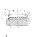
figure 4 illustre, en vue en coupe, les principaux composants d'un appareil d'éclairage et un inducteur pour l'alimentation par induction de l'appareil d'éclairage, selon un mode de réalisation. - La
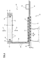
figure 5 illustre, en vue en coupe, les principaux composants d'un appareil d'éclairage et un inducteur pour l'alimentation par induction de l'appareil d'éclairage, selon un autre mode de réalisation. - La
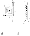
figure 6 illustre, en vue en coupe, une inductance d'un appareil d'éclairage ou d'un générateur selon un mode de réalisation. - La
figure 7 est un schéma illustrant les principaux composants - et leurs interconnexions - d'un module d'alimentation par induction d'un appareil d'éclairage, selon un mode de réalisation. - La
figure 8 est un schéma illustrant les principaux composants - et leurs interconnexions - d'un module de télécommande d'un appareil d'éclairage et/ou de télécommande d'un module d'alimentation par induction de cet appareil d'éclairage, selon un mode de réalisation. - La
figure 9 illustre, en vue en plan, une inductance d'un appareil d'éclairage ou d'un générateur selon un mode de réalisation. - La
figure 10 illustre, en vue en perspective schématique, un meuble équipé d'un système d'alimentation par induction et lafigure 11 illustre, du même point de vue que pour lafigure 10 , le meuble de cette figure auquel est suspendu un appareil d'éclairage. - Par référence aux
figures 1 à 3 notamment, l'appareil d'éclairage 20 comporte un guide 27 de lumière, mince et transparent, éclairé par ses deux bords ou tranches 25, 26 opposé(e)s, par des LEDs 23, 24 respectivement disposées en regard de ces deux bords. - Selon la puissance lumineuse requise, l'appareil comporte le nombre nécessaire de LEDs qui sont disposées en rangées réparties le long d'une ou plusieurs des faces latérales 25, 26 par lesquelles la lumière émise par les LEDs est introduite dans le guide.
- Par référence à la
figure 1 , les LEDs 23, 24 sont raccordées en parallèle aux bornes d'une inductance 22. - Les LEDs 23, 24 et l'inductance 22 sont disposées à l'intérieur d'un boîtier 21 comportant des parois opaques délimitant une ouverture en regard de laquelle s'étend le guide 27 de lumière.
- L'appareil 20 est conçu pour être alimenté par un module 70 d'alimentation qui comporte une inductance 78 connectée aux bornes d'un générateur 73 de courant alternatif.
- Par référence à la
figure 4 notamment, le guide 27 présente deux faces principales 50, 51 (c'est-à-dire les faces de plus grande(s) surface ou dimensions) qui sont sensiblement parallèles, et des faces latérales ou tranches 25, 26 reliant les faces principales 50, 51. - Les faces principales du guide peuvent être planes, notamment lorsque le guide 27 est en forme de plaque plane, ou bien incurvées, par exemple lorsque le guide 27 est en forme de calotte cylindrique ou de plaque cintrée (gauche).
- Le guide 27 est réalisé dans un matériau optique tel que du verre, du polycarbonate, ou du polyméthacrylate de méthyle (PMMA), et présente une épaisseur (repère 55
figure 4 ) située dans une plage allant de un millimètre environ à cinq millimètres environ. - La face principale « avant » 50 du guide est munie de motifs 52 diffusants, et un réflecteur 62 est prévu sur - ou accolé contre - la face « arrière » 51 du guide 27.
- Selon un mode de réalisation non représenté, la face principale « arrière » 51 du guide est munie des motifs 52 diffusants. Un réflecteur est prévu sur - ou accolé contre - la face « arrière » du guide, et un film diffuseur est en outre prévu sur - ou accolé contre - la face « avant » du guide 27.
- Les motifs ou éléments diffusants 52 peuvent être constitués de saillies ou de dépressions allongées, formées ou disposées sur la face 50.
- Les motifs 52 peuvent être essentiellement constituées de rainures formées sur la face 50 à l'aide d'un faisceau laser, dont l'espacement mutuel varie le long d'au moins un axe.
- En particulier, l'espacement des rainures peut décroître régulièrement d'une zone périphérique du guide à une zone centrale du guide.
- La largeur des rainures diffusantes peut être située dans une plage allant de 50 microns environ à 100 microns environ.
- Notamment lorsque le guide est en forme de plaque polygonale, en particulier rectangulaire, les motifs diffusants peuvent s'étendre selon des axes parallèles aux bords du guide, et/ou des axes parallèles aux rangées de LEDs disposées à faible distance de - ou contre - ces bords.
- Lorsque le guide est en forme de disque, les motifs diffusants peuvent s'étendre selon des cercles concentriques.
- La lumière 60 émise par les LEDs subit des réflexions multiples à l'intérieur du guide 27. Les éléments diffusants 52 provoquent une diffusion de la lumière émise par les LEDs et se propageant dans le guide, vers chacune des deux faces 50, 51 principales opposées du guide 27.
- En raison notamment de la présence du réflecteur sur la face 51, les flux lumineux respectivement émis par chacune des LEDs s'ajoutent - se mélangent - et résultent en un flux lumineux homogène 63 qui sort du guide par sa face principale « avant » 50.
- Les LEDs 23 et 24 peuvent présenter des spectres d'émission respectifs différents. En particulier, les LEDS 23 présentent un spectre d'émission présentant deux maxima pour deux premières longueurs d'onde, et les LEDS 24 présentent un spectre d'émission présentant deux maxima pour deux secondes longueurs d'onde dont au moins une est distincte des deux premières longueurs d'onde.
- Les premières et secondes longueurs d'onde sont généralement situées dans une plage allant de 400 nanomètres environ à 800 nanomètres environ, de sorte que les LEDs 23, 24 peuvent émettre respectivement des flux de lumière « blanche » dont les températures de couleur différent : un flux de lumière bleuâtre dont la température de couleur peut être supérieure à 5500 Kelvin (K), et un flux de lumière jaunâtre dont la température de couleur peut être inférieure à 5500 K, par exemple.
- Alternativement ou en complément, certaines des LEDs peuvent émettre dans le domaine de l'infrarouge ou de l'ultraviolet.
- Le « mélange », dans le guide 27, des flux lumineux des différentes LEDs permet de compenser les disparités de ces flux « individuels » qui peuvent résulter des disparités constatées pour la tension directe des LEDs d'un modèle déterminé, et à fortiori de compenser les disparités de ces flux résultant de l'emploi de LEDs de modèles distincts - qui présentent des spectres d'émission distincts - .
- Par référence à la
figure 2 , l'appareil 20 comporte une capacité 28 et un redresseur 29 raccordés en série avec l'inductance 22. - La capacité 28 est choisie pour former, avec l'inductance 22, un circuit oscillant accordé sur - i.e. résonnant à - une fréquence correspondant sensiblement à la fréquence du générateur (repère 70
figures 1 et7 ) de courant, dont la valeur peut être située dans une plage allant de 10 à 15 kHz environ, jusqu'à 25 ou 30 kHz environ. - Le redresseur 29 peut être constitué par un pont de diodes délivrant un courant redressé entre ses bornes de sorties, qui alimente au moins deux groupes de LEDS 23, 24 raccordés en parallèle, chaque groupe de LEDs comportant plusieurs LEDS raccordées en série.
- Les LEDs 23, 24 de type CMS peuvent être montées sur des circuits imprimés 40, 41 (
figure 4 ) s'étendant en regard des tranches 25, 26 du guide 27. - Par référence à la
figure 3 , l'appareil 20 comporte en outre deux interrupteurs 30, 31 respectivement raccordés en série avec les groupes de LEDs 23, 24. - Chaque interrupteur peut être essentiellement constitué par un transistor, en particulier un transistor à effet de champ de type MOSFET.
- L'appareil 20 comporte également une unité de commande 32, telle qu'un micro contrôleur, arrangée (programmée) pour commander l'ouverture et la fermeture des interrupteurs 30, 31, par l'intermédiaire de liaisons 36, pour assurer un éclairement avec l'intensité et le cas échéant la colorimétrie souhaitée.
- A cet effet, des modules de commande (non représentés) de type à modulation de largeur d'impulsion (« PWM ») peut être intégrés à l'unité 32 ou interposés entre cette unité et les interrupteurs, pour contrôler l'alimentation des diodes 23, 24.
- L'unité de commande 32 est alimentée par un module d'alimentation 33 raccordé aux sorties du redresseur 29, par l'intermédiaire de conducteurs 37.
- L'unité de commande 32 est également reliée à un transmetteur 34 de signaux et/ou de données, par une liaison bidirectionnelle 39, ainsi qu'à un capteur 35 de mouvement par une liaison 38.
- Le transmetteur 34 peut être essentiellement constitué par un émetteur-récepteur de signaux de commande radio, en particulier un transmetteur Bluetooth®.
- Le transmetteur 34 permet à l'unité de commande 32 de recevoir des données de commandes transmises à l'appareil 20 par un autre appareil disposé à proximité de l'appareil 20 et équipé d'un transmetteur compatible avec le transmetteur 34, tel qu'un appareil de télécommande de l'appareil 20.
- Le capteur 35 de mouvement peut être essentiellement constitué par un ou plusieurs accéléromètre(s) ou gyromètre(s) solidaires du boîtier 21 de l'appareil 20.
- Le capteur 35 peut par exemple comporter deux ou trois accéléromètres respectivement sensibles aux accélérations du boîtier selon deux ou trois axes orthogonaux deux à deux.
- Le capteur 35 de mouvement permet à l'unité de commande 32 de détecter des mouvements de l'appareil d'éclairage 20 et de modifier en conséquence les signaux de commande délivrés par l'unité 32 aux interrupteurs 30, 31.
- En particulier, l'unité 32 peut être programmée pour faire varier (augmenter ou au contraire diminuer) le flux lumineux émis par les LEDs 23 et/ou par les LEDs 24 en fonction des signaux que lui délivre le capteur 35.
- Selon un mode de réalisation, le capteur 35 comporte un premier accéléromètre sensible aux accélérations du boîtier selon un premier axe (une première direction), de manière à permettre à l'unité 32 de faire varier le flux lumineux émis par un premier groupe de LEDs 23 en fonction de mouvements impartis au boîtier par un utilisateur selon cet axe, et le capteur 35 comporte un second accéléromètre sensible aux accélérations du boîtier selon un second axe orthogonal au premier axe, de manière à permettre à l'unité 32 de faire varier le flux lumineux émis par un second groupe de LEDs 24 en fonction de mouvements impartis au boîtier selon ce second axe.
- Par référence aux
figures 4 et5 , le boîtier comporte une paroi plane 43 formant un fond, et des parois 42, 44 s'étendant à partir de la paroi 43 et délimitant une ouverture 45 qui est fermée par le guide 27. - Les parois opaques 42 à 44 du boîtier et le guide interdisent ainsi la sortie de la lumière 60 injectée par les LEDs dans le guide, hors du boîtier, autrement que par la face avant 50 du guide.
- L'inductance 22 est solidaire de la paroi 43 sur la face intérieure de laquelle elle s'étend.
- Notamment lorsque le boîtier et la paroi 43 présentent une forme rectangulaire, l'inductance 22 servant d'induit peut être formée par un conducteur présentant une forme de spirale sensiblement rectangulaire ; il peut en être de même concernant l'inductance 78 servant d'inducteur.
- L'inductance 22 peut dans certains cas être réalisée sous forme de pistes d'un circuit imprimé, ou par bobinage d'un fil conducteur revêtu d'un isolant; de préférence, cependant, l'inductance 22 est réalisée par découpe ou gravure, à partir d'une feuille d'un matériau conducteur.
- Par référence aux
figures 4 et9 notamment, l'inductance 22 est formée d'une bande ou piste d'un matériau conducteur tel que du cuivre, qui comporte plusieurs segments rectilignes successifs tels que ceux repérés 46 à 48figure 9 . - L'inductance 22 comporte une borne 49, 53 à chacune de ses deux extrémités, pour son raccordement aux composants 28, 29 de l'appareil 20.
- L'épaisseur 54 des segments conducteurs de l'inductance 22 peut être située dans une plage allant de 0.2 millimètre environ à 0.6 ou 1 millimètre environ, en particulier de l'ordre de 0.3 à 0.6 millimètre. La largeur 57 de ces segments peut être au moins égale à leur épaisseur.
- L'inductance illustrée
figure 9 peut être obtenue par gravure ou découpe d'une feuille de cuivre, de façon à ménager un espace suffisant entre deux segments conducteurs adjacents. Le conducteur en spirale ainsi obtenu présente une section sensiblement rectangulaire et peut être revêtu d'un - ou noyé dans un - matériau isolant. - La même technique peut être utilisée pour fabriquer l'inductance 78 du générateur. Dans ce cas, la largeur 88 des segments conducteurs peut être au moins égale au double ou au triple de leur épaisseur 87 (
figure 5 ). - Dans le mode de réalisation de l'inductance 22 qui est illustré
figure 6 , l'inductance est obtenue par enroulement d'un fil conducteur 58 de section rectangulaire revêtu d'un isolant 59, de façon à former une spirale à « spires » jointives présentant l'épaisseur 54. - Ces procédés de réalisation permettent d'obtenir des inductances susceptibles d'être déformées pour épouser une forme gauche (non plane).
- La paroi 43 de fond du boîtier 21 peut présenter une épaisseur de l'ordre d'un ou plusieurs millimètre(s), et le boîtier 21 peut présenter une épaisseur 56 de l'ordre de 10 ou 20 millimètres.
- Cette paroi 43 peut être réalisée en matière plastique, en particulier dans une matière plastique comportant une charge minérale sous forme de poudre ou de particules de petite taille.
- Dans le mode de réalisation illustré
figure 4 , un aimant 61 est en partie au moins inclus dans la paroi 43, sur la face extérieure de laquelle l'aimant est sensiblement affleurant. - L'aimant permet de suspendre l'appareil 20 à une paroi 64 verticale incluant un inducteur 78 adapté pour alimenter l'appareil 20 par induction, comme illustré
figures 4 ,10, et 11 . - A cet effet, la paroi comporte une structure métallique 65 disposée sensiblement affleurante à la face externe 66 de la paroi 64, et adaptée pour provoquer, lorsqu'elle est placée dans le champ magnétique de l'aimant 61, une force d'attraction mutuelle entre les parois 43 et 64 qui est suffisante pour compenser le poids de l'appareil 20.
- Dans le mode de réalisation illustré
figure 5 , le boîtier de l'appareil 20 comporte une base 43 plane par laquelle l'appareil repose sur la face supérieure 86 d'un support 68 plan faisant partie d'un meuble 85, la base 43 incorporant l'induit 22. - Le boîtier comporte des parois opaques 42, 44 cerclant le guide 27 et renfermant, avec le guide, les circuits imprimés 40, 41 recevant les LEDs.
- Le boîtier comporte également un bras 84 reliant la partie supérieure du boîtier - i.e. les parois 42, 44 - à la base 43. A l'intérieur du bras 84 cheminent des conducteurs 69 servant à relier l'induit 22 aux circuits imprimés 40, 41.
- Dans ce mode de réalisation, les motifs 52 diffusants provoquent l'émission du flux lumineux 63 par les deux faces principales du guide.
- Le support 68 sous lequel est collé l'inducteur 78 peut former une partie au moins du plateau horizontal d'un meuble 85 tel qu'une table ou un bureau.
- La base 43 et/ou le support 68 peu(ven)t être réalisée(s) dans une matière plastique comportant une charge minérale telle que du quartz ou un hydrate d'alumine, ce qui permet de limiter l'échauffement des parois 43, 68 placées dans le champ magnétique produit par l'inducteur, sans affaiblir ou perturber ce champ magnétique, et permet le cas échéant de diffuser la chaleur produite par les LEDs.
- Par exemple, la base et le support peuvent être fabriqués à partir de plaques de Corian® proposées par la société Du Pont de Nemours.
- Par référence à la
figure 7 , le module d'alimentation - ou générateur - 70 comporte, à l'intérieur d'un boîtier 71, un convertisseur produisant un courant alternatif à une fréquence correspondant sensiblement à celle du circuit résonant de l'appareil à alimenter. - A cet effet, le convertisseur comporte un pont en « H » dont la branche centrale est constituée de l'inducteur 78 raccordé en série avec une capacité 79.
- Les quatre interrupteurs 74 à 77 du pont en « H » peuvent être respectivement constitués de quatre transistors de type MOSFET.
- La commande des transistors 74 à 77 est assurée par une unité de commande 72, telle qu'un microcontrôleur.
- Le microcontrôleur 72 reçoit à cet effet les signaux/données délivré(e)s par un convertisseur 80 raccordé à un capteur 83 de courant sensible au courant traversant l'inductance 78, d'une part, et les signaux/données délivré(e)s par un autre convertisseur 81 servant à mesurer la tension dans le pont, d'autre part.
- Selon une variante de réalisation non représentée, le capteur de courant 83 est inséré dans la branche centrale du pont en « H », entre la capacité 79 et l'inductance 78.
- Selon une autre variante de réalisation non représentée, le pont en « H » peut être remplacé par un demi pont.
- Le capteur de courant 83 peut être utilisé pour détecter les variations du courant traversant l'inductance 78 et pour en déduire la présence - ou l'absence - d'un induit dans le champ magnétique produit par l'inductance 78 ; il peut ainsi être utilisé pour détecter la présence d'un appareil à alimenter par induction.
- Le microcontrôleur 72 est également relié à un transmetteur 82 radio, pour envoyer des données de commande à l'appareil 20 et/ou pour recevoir des données de commande émises par un appareil de télécommande du générateur 70.
- Par référence à la
figure 8 , l'appareil 90 de télécommande comporte, à l'intérieur d'un boîtier 91, une unité de commande 92, telle qu'un microcontrôleur, qui est relié à un afficheur 93 et à un clavier comportant au moins une touche 94 permettant la validation de choix faits par un utilisateur. - Le microcontrôleur 92 est également relié à un transmetteur 95 radio pour envoyer des données de commande à l'appareil 20 et/ou au générateur 70, ainsi qu'à une horloge 96.
- Le microcontrôleur 92 est aussi relié à trois capteurs : un capteur 97 sensible à l'intensité (globale) du flux lumineux ambiant, i.e. du flux incident sur la télécommande 90 ; un capteur 98 sensible à plusieurs bandes spectrales du flux lumineux ambiant ; et un capteur 99 sensible aux mouvements du boîtier 91.
- Le capteur 97 peut comporter une seule photodiode et le capteur 98 peut comporter plusieurs photodiodes ou groupes de photodiodes présentant des spectres de réception - de sensibilité - distincts.
- L'unité de commande 92 peut être programmée pour émettre, par l'intermédiaire du transmetteur 95, des signaux de commande de l'appareil 20 d'éclairage, afin de faire varier le spectre ou l'intensité de la lumière émise par les LEDs de cet appareil, en fonction notamment des signaux qui lui sont délivrés par les photodiodes.
- L'analyse de la lumière ambiante détectée par les photodiodes 97, 98 permet au microcontrôleur 92 de déterminer si le niveau et/ou le spectre d'éclairement requis par un utilisateur demande un éclairage complémentaire par les LEDs de l'appareil 20.
- Notamment lorsqu'une seule photodiode est prévue, l'analyse des signaux délivrés par les photodiodes peut se faire « en intégrale », en utilisant par exemple un filtre correspondant à la sensibilité d'un oeil humain.
- Lorsque plusieurs photodiodes sont prévues, l'analyse peut se faire « en colorimétrie », en comparant le niveau d'éclairement mesuré dans plusieurs bandes spectrales - i.e. plusieurs plages de longueurs d'onde - à des niveaux d'éclairement déterminés.
- Des niveaux d'éclairement prédéterminés peuvent être enregistrés dans une mémoire et peuvent être lus par le microcontrôleur 92 pour assurer un éclairage selon un mode d'éclairage choisi par l'utilisateur. Le mode d'éclairage peut par exemple être choisi parmi un mode d'éclairage constant en lumière blanche, un mode d'éclairage d'intensité variable selon un cycle journalier, ou un mode d'éclairage intensif.
- Afin que l'information transmise par les capteurs 97, 98 soit fiable, ceux-ci peuvent être associés à un (équipés d'un) masque permettant d'éviter un éclairement direct des capteurs par l'appareil 20 et/ou par un rayonnement solaire direct.
- Dans le même but, les capteurs 97, 98 peuvent être associés à un organe optique leur assurant un large champ de « vision », à un filtre, ou à un verre dépoli.
- Selon un mode de réalisation non représenté, les capteurs 97, 98 peuvent être intégrés à l'appareil d'éclairage 20 et reliés à l'unité de commande de cet appareil. Dans ce cas notamment, ces capteurs peuvent être en outre arrangés pour recevoir et détecter des signaux optiques de télécommande émis par un émetteur optique adapté intégré au dispositif 90 de télécommande.
- Selon autre un mode de réalisation non représenté, les capteurs 97, 98 peuvent être intégrés à un meuble ou une structure comportant le circuit d'induction, et/ou au générateur 70.
- Le capteur 99 de mouvement permet à l'unité de commande 92 de détecter des mouvements du boîtier 91 et de modifier en conséquence les signaux de commande délivrés par l'unité 92, comme décrit ci avant concernant le capteur 35 de mouvement intégré au boîtier de l'appareil 20.
- Par référence aux
figures 10 et 11 , le meuble 85 comporte un socle 100 par l'intermédiaire duquel le meuble peut reposer sur le sol par exemple, ainsi qu'un panneau 101 solidaire du socle et s'étendant verticalement à partir de ce dernier. - Un inducteur 78 conformé en spirale de contour rectangulaire, allongé verticalement, ainsi que deux armatures métalliques 104 en forme de barres verticales, sont disposés à l'intérieur du panneau 101.
- Le socle 100 abrite un circuit (73
figure 1 ) d'alimentation de l'inducteur 78, le circuit (non représenté) étant relié aux deux bornes de l'inducteur. Les armatures magnétiques 104, qui s'étendent sensiblement sur toute la hauteur 102 de l'inducteur 78, permettent à un luminaire 20 (figure 11 ) dont la hauteur 103 est moindre que celle de l'inducteur et qui est équipé d'aimants adaptés, d'être suspendu au meuble 85 grâce à la force d'attraction mutuelle des aimants et des armatures 104, et ceci à différentes hauteurs le long de l'axe longitudinal vertical du panneau 101.
Claims (15)
- Meuble ou construction (85) comportant une paroi (64, 68, 101) apte à recevoir un appareil (20) sur sa face (66, 86) externe, une inductance (78) pour l'alimentation par induction de l'appareil (20), l'inductance (78) étant solidaire de la paroi (64, 68, 101) et s'étendant sensiblement parallèlement à la face (66, 86) externe de la paroi, l'inductance comportant des conducteurs (46 à 48) formant une spirale et revêtus d'un - ou noyés dans un - matériau électriquement isolant, caractérisé ou caractérisée en ce que les conducteurs (46 à 48) sont de section sensiblement rectangulaire et en ce que la paroi comporte un mélange de matière plastique et de particules minérales.
- Meuble ou construction selon la revendication 1 dans lequel ou laquelle l'épaisseur (87) des conducteurs est située dans une plage allant de 0.2 millimètre environ jusqu'à 1 millimètre environ, en particulier de l'ordre de 0.3 à 0.6 millimètre.
- Meuble ou construction selon l'une quelconque des revendications 1 ou 2 dans lequel ou laquelle la paroi est essentiellement constituée d'un mélange de résine acrylique et de particules minérales.
- Meuble ou construction selon l'une quelconque des revendications 1 à 3 dans lequel ou laquelle la paroi est essentiellement constituée d'un mélange de matière plastique et de particules de quartz et/ou d'hydrate d'alumine.
- Meuble ou construction selon l'une quelconque des revendications 1 à 4 dans lequel ou laquelle la paroi (64, 68, 101) s'étend sensiblement horizontalement.
- Meuble ou construction selon l'une quelconque des revendications 1 à 4 dans lequel ou laquelle la paroi (64, 68, 101) s'étend sensiblement verticalement.
- Meuble ou construction selon l'une quelconque des revendications 1 à 6 dans lequel ou laquelle la paroi (64, 68, 101) présente une épaisseur située dans une plage allant de 1 millimètre environ à 50 millimètres environ.
- Meuble ou construction selon l'une quelconque des revendications 1 à 7 dans lequel ou laquelle la paroi comporte une structure magnétique (65, 104) disposée sensiblement affleurante à la face externe (66) de la paroi (64), et adaptée pour provoquer, lorsqu'elle est placée dans le champ magnétique d'un aimant (61) solidaire de l'appareil (20), une force d'attraction mutuelle entre l'appareil (20) et le meuble ou la construction (85).
- Meuble ou construction selon l'une quelconque des revendications 1 à 8 dans lequel ou laquelle l'inductance est solidarisée à la paroi par collage.
- Système d'alimentation par induction d'un appareil (20) conçu pour être alimenté par ce système, quel système comporte un meuble ou une construction selon l'une quelconque des revendications 1 à 9, et un générateur (73) arrangé pour alimenter l'inductance (78) du meuble ou de la construction (85).
- Système selon la revendication 10 dans lequel le générateur comporte un pont ou un demi pont (74 à 79) dans lequel l'inductance (78) est raccordée en série avec une capacité (79), et une unité de commande (72) arrangée pour piloter les interrupteurs (74 à 77) du pont ou demi pont.
- Système selon la revendication 11 dans lequel le générateur comporte un transmetteur (82) radio relié à l'unité de commande (72) et permettant à l'unité de commande de recevoir des données de commande du pont.
- Système selon l'une quelconque des revendications 10 à 12 qui comporte un appareil (90) de télécommande du générateur (73) et/ou de l'appareil (20), qui comporte un ou plusieurs capteurs (97, 98) sensibles au flux lumineux incident ambiant, en particulier plusieurs capteurs (98) respectivement sensibles à différentes bandes spectrales du flux lumineux incident ambiant.
- Système selon l'une quelconque des revendications 10 à 13 qui comporte un appareil (90) de télécommande du générateur (73) et/ou de l'appareil (20), qui comporte un capteur (99) de mouvement solidaire du boîtier (91) de l'appareil (90) de télé commande, qui permet de détecter des mouvements de l'appareil de (télé)commande et de modifier en conséquence les signaux de commande délivrés au générateur (73) et/ou à l'appareil (20).
- Procédé de fabrication d'un meuble ou d'une construction (85) selon l'une quelconque des revendications 1 à 9, procédé dans lequel l'inductance (78) est obtenue par découpe ou gravure d'une feuille d'un matériau conducteur tel que du cuivre, puis en recouvrant la pièce ainsi obtenue dudit matériau électriquement isolant.
Applications Claiming Priority (2)
| Application Number | Priority Date | Filing Date | Title |
|---|---|---|---|
| FR1000025A FR2954994B1 (fr) | 2010-01-05 | 2010-01-05 | Systeme d'alimentation par induction et meuble pour un tel systeme |
| PCT/FR2011/000003 WO2011083259A1 (fr) | 2010-01-05 | 2011-01-04 | Systeme d'alimentation par induction et meuble pour un tel systeme |
Publications (2)
| Publication Number | Publication Date |
|---|---|
| EP2522025A1 EP2522025A1 (fr) | 2012-11-14 |
| EP2522025B1 true EP2522025B1 (fr) | 2020-03-25 |
Family
ID=42542833
Family Applications (1)
| Application Number | Title | Priority Date | Filing Date |
|---|---|---|---|
| EP11705002.1A Active EP2522025B1 (fr) | 2010-01-05 | 2011-01-04 | Systeme d'alimentation par induction et meuble pour un tel systeme |
Country Status (4)
| Country | Link |
|---|---|
| EP (1) | EP2522025B1 (fr) |
| BR (1) | BR112012016566A2 (fr) |
| FR (1) | FR2954994B1 (fr) |
| WO (1) | WO2011083259A1 (fr) |
Families Citing this family (2)
| Publication number | Priority date | Publication date | Assignee | Title |
|---|---|---|---|---|
| EP2884626A4 (fr) * | 2012-08-07 | 2016-07-20 | Lequio Power Technology Corp | Système d'éclairage, dispositif d'alimentation électrique et équipement de lumière |
| AT14189U1 (de) * | 2013-11-12 | 2015-05-15 | Tridonic Gmbh & Co Kg | LED-Modul, LED-Konverter und Verfahren zum Betreiben wenigstens einer Leuchtdiode |
Family Cites Families (6)
| Publication number | Priority date | Publication date | Assignee | Title |
|---|---|---|---|---|
| CH581937A5 (fr) * | 1973-05-25 | 1976-11-15 | Sachs Systemtechnik Gmbh | |
| DE2415087A1 (de) * | 1974-03-28 | 1975-10-09 | Sachs Systemtechnik Gmbh | Lichtquellenanordnung mit elektrischen niederspannungslampen |
| US5264997A (en) * | 1992-03-04 | 1993-11-23 | Dominion Automotive Industries Corp. | Sealed, inductively powered lamp assembly |
| FR2695285B3 (fr) * | 1992-09-02 | 1994-07-29 | Cableco Sa | Ensemble d'eclairage comprenant une lampe alimentee par le secteur. |
| EP2039070A2 (fr) * | 2006-06-27 | 2009-03-25 | Nxp B.V. | Coexistence programmée |
| US7909483B2 (en) | 2006-07-21 | 2011-03-22 | Koninklijke Philips Electronics N.V. | Lighting system |
-
2010
- 2010-01-05 FR FR1000025A patent/FR2954994B1/fr not_active Expired - Fee Related
-
2011
- 2011-01-04 EP EP11705002.1A patent/EP2522025B1/fr active Active
- 2011-01-04 WO PCT/FR2011/000003 patent/WO2011083259A1/fr not_active Ceased
- 2011-01-04 BR BR112012016566A patent/BR112012016566A2/pt not_active Application Discontinuation
Non-Patent Citations (1)
| Title |
|---|
| None * |
Also Published As
| Publication number | Publication date |
|---|---|
| FR2954994B1 (fr) | 2019-06-07 |
| WO2011083259A1 (fr) | 2011-07-14 |
| FR2954994A1 (fr) | 2011-07-08 |
| EP2522025A1 (fr) | 2012-11-14 |
| BR112012016566A2 (pt) | 2016-04-05 |
Similar Documents
| Publication | Publication Date | Title |
|---|---|---|
| WO2001008228A1 (fr) | Lentille en masse, corps luminescent, dispositif d'eclairage et systeme d'information optique | |
| US7810953B2 (en) | Illuminating device | |
| EP2522201B1 (fr) | Appareil d'éclairage et système d'alimentation par induction d'un tel appareil | |
| CN102252224B (zh) | 光单元及具有该光单元的显示装置 | |
| CN101925804B (zh) | 具有光敏元件的照明单元 | |
| US20160018588A1 (en) | Lighting assembly | |
| CN104040810B (zh) | 具有波长测量功能的波长可变激光装置 | |
| TWI848140B (zh) | 結合增強安全特徵及熱管理之發光模組 | |
| TW201602490A (zh) | 具有用於減少內部組件之視覺影響之特徵之光電模組 | |
| EP0377352A1 (fr) | Bande éclairante souple à diodes électroluminescentes | |
| WO2016097322A1 (fr) | Dispositif d'eclairage et/ou de signalisation comportant un guide de lumiere | |
| FR2883653A1 (fr) | Module electronique et carte a puce avec indicateur lumineux | |
| US20120155078A1 (en) | Hybrid illumination systems and methods | |
| FR2954994B1 (fr) | Systeme d'alimentation par induction et meuble pour un tel systeme | |
| WO2011048319A1 (fr) | Dispositif d'eclairage a diodes electroluminescentes | |
| US8070311B2 (en) | Solar LED lamp | |
| JP2002228921A (ja) | バルク型レンズ及びそれを用いた発光体、照明器具及び光情報システム | |
| US20170167717A1 (en) | Diffractive and prismatic oled wireless and led wireless underwater pool light sources | |
| CN108614383A (zh) | 泛光灯组件、泛光灯损坏的检测方法和电子装置 | |
| JP6198120B2 (ja) | 発光モジュール及びそれを用いた照明装置 | |
| CN104850839A (zh) | 光学采集模组的光控制组件及成型方法 | |
| US20130294075A1 (en) | Lighting system and method of manufacture | |
| KR20120033021A (ko) | 솔라브릭 | |
| KR102119808B1 (ko) | 백라이트 장치 | |
| CN108626583A (zh) | 发光二极管面光源灯具 |
Legal Events
| Date | Code | Title | Description |
|---|---|---|---|
| PUAI | Public reference made under article 153(3) epc to a published international application that has entered the european phase |
Free format text: ORIGINAL CODE: 0009012 |
|
| 17P | Request for examination filed |
Effective date: 20120806 |
|
| AK | Designated contracting states |
Kind code of ref document: A1 Designated state(s): AL AT BE BG CH CY CZ DE DK EE ES FI FR GB GR HR HU IE IS IT LI LT LU LV MC MK MT NL NO PL PT RO RS SE SI SK SM TR |
|
| DAX | Request for extension of the european patent (deleted) | ||
| STAA | Information on the status of an ep patent application or granted ep patent |
Free format text: STATUS: EXAMINATION IS IN PROGRESS |
|
| 17Q | First examination report despatched |
Effective date: 20170904 |
|
| GRAP | Despatch of communication of intention to grant a patent |
Free format text: ORIGINAL CODE: EPIDOSNIGR1 |
|
| STAA | Information on the status of an ep patent application or granted ep patent |
Free format text: STATUS: GRANT OF PATENT IS INTENDED |
|
| INTG | Intention to grant announced |
Effective date: 20190212 |
|
| GRAJ | Information related to disapproval of communication of intention to grant by the applicant or resumption of examination proceedings by the epo deleted |
Free format text: ORIGINAL CODE: EPIDOSDIGR1 |
|
| STAA | Information on the status of an ep patent application or granted ep patent |
Free format text: STATUS: EXAMINATION IS IN PROGRESS |
|
| INTC | Intention to grant announced (deleted) | ||
| GRAP | Despatch of communication of intention to grant a patent |
Free format text: ORIGINAL CODE: EPIDOSNIGR1 |
|
| STAA | Information on the status of an ep patent application or granted ep patent |
Free format text: STATUS: GRANT OF PATENT IS INTENDED |
|
| INTG | Intention to grant announced |
Effective date: 20191108 |
|
| GRAS | Grant fee paid |
Free format text: ORIGINAL CODE: EPIDOSNIGR3 |
|
| GRAA | (expected) grant |
Free format text: ORIGINAL CODE: 0009210 |
|
| STAA | Information on the status of an ep patent application or granted ep patent |
Free format text: STATUS: THE PATENT HAS BEEN GRANTED |
|
| AK | Designated contracting states |
Kind code of ref document: B1 Designated state(s): AL AT BE BG CH CY CZ DE DK EE ES FI FR GB GR HR HU IE IS IT LI LT LU LV MC MK MT NL NO PL PT RO RS SE SI SK SM TR |
|
| RAP1 | Party data changed (applicant data changed or rights of an application transferred) |
Owner name: PHLOX |
|
| REG | Reference to a national code |
Ref country code: GB Ref legal event code: FG4D Free format text: NOT ENGLISH |
|
| REG | Reference to a national code |
Ref country code: AT Ref legal event code: REF Ref document number: 1249527 Country of ref document: AT Kind code of ref document: T Effective date: 20200415 Ref country code: IE Ref legal event code: FG4D Free format text: LANGUAGE OF EP DOCUMENT: FRENCH |
|
| REG | Reference to a national code |
Ref country code: DE Ref legal event code: R096 Ref document number: 602011065817 Country of ref document: DE |
|
| REG | Reference to a national code |
Ref country code: CH Ref legal event code: NV Representative=s name: VALIPAT S.A. C/O BOVARD SA NEUCHATEL, CH |
|
| REG | Reference to a national code |
Ref country code: NL Ref legal event code: FP |
|
| PG25 | Lapsed in a contracting state [announced via postgrant information from national office to epo] |
Ref country code: FI Free format text: LAPSE BECAUSE OF FAILURE TO SUBMIT A TRANSLATION OF THE DESCRIPTION OR TO PAY THE FEE WITHIN THE PRESCRIBED TIME-LIMIT Effective date: 20200325 Ref country code: RS Free format text: LAPSE BECAUSE OF FAILURE TO SUBMIT A TRANSLATION OF THE DESCRIPTION OR TO PAY THE FEE WITHIN THE PRESCRIBED TIME-LIMIT Effective date: 20200325 Ref country code: NO Free format text: LAPSE BECAUSE OF FAILURE TO SUBMIT A TRANSLATION OF THE DESCRIPTION OR TO PAY THE FEE WITHIN THE PRESCRIBED TIME-LIMIT Effective date: 20200625 |
|
| PG25 | Lapsed in a contracting state [announced via postgrant information from national office to epo] |
Ref country code: SE Free format text: LAPSE BECAUSE OF FAILURE TO SUBMIT A TRANSLATION OF THE DESCRIPTION OR TO PAY THE FEE WITHIN THE PRESCRIBED TIME-LIMIT Effective date: 20200325 Ref country code: BG Free format text: LAPSE BECAUSE OF FAILURE TO SUBMIT A TRANSLATION OF THE DESCRIPTION OR TO PAY THE FEE WITHIN THE PRESCRIBED TIME-LIMIT Effective date: 20200625 Ref country code: LV Free format text: LAPSE BECAUSE OF FAILURE TO SUBMIT A TRANSLATION OF THE DESCRIPTION OR TO PAY THE FEE WITHIN THE PRESCRIBED TIME-LIMIT Effective date: 20200325 Ref country code: HR Free format text: LAPSE BECAUSE OF FAILURE TO SUBMIT A TRANSLATION OF THE DESCRIPTION OR TO PAY THE FEE WITHIN THE PRESCRIBED TIME-LIMIT Effective date: 20200325 Ref country code: GR Free format text: LAPSE BECAUSE OF FAILURE TO SUBMIT A TRANSLATION OF THE DESCRIPTION OR TO PAY THE FEE WITHIN THE PRESCRIBED TIME-LIMIT Effective date: 20200626 |
|
| REG | Reference to a national code |
Ref country code: LT Ref legal event code: MG4D |
|
| PG25 | Lapsed in a contracting state [announced via postgrant information from national office to epo] |
Ref country code: RO Free format text: LAPSE BECAUSE OF FAILURE TO SUBMIT A TRANSLATION OF THE DESCRIPTION OR TO PAY THE FEE WITHIN THE PRESCRIBED TIME-LIMIT Effective date: 20200325 Ref country code: PT Free format text: LAPSE BECAUSE OF FAILURE TO SUBMIT A TRANSLATION OF THE DESCRIPTION OR TO PAY THE FEE WITHIN THE PRESCRIBED TIME-LIMIT Effective date: 20200818 Ref country code: SM Free format text: LAPSE BECAUSE OF FAILURE TO SUBMIT A TRANSLATION OF THE DESCRIPTION OR TO PAY THE FEE WITHIN THE PRESCRIBED TIME-LIMIT Effective date: 20200325 Ref country code: EE Free format text: LAPSE BECAUSE OF FAILURE TO SUBMIT A TRANSLATION OF THE DESCRIPTION OR TO PAY THE FEE WITHIN THE PRESCRIBED TIME-LIMIT Effective date: 20200325 Ref country code: LT Free format text: LAPSE BECAUSE OF FAILURE TO SUBMIT A TRANSLATION OF THE DESCRIPTION OR TO PAY THE FEE WITHIN THE PRESCRIBED TIME-LIMIT Effective date: 20200325 Ref country code: IS Free format text: LAPSE BECAUSE OF FAILURE TO SUBMIT A TRANSLATION OF THE DESCRIPTION OR TO PAY THE FEE WITHIN THE PRESCRIBED TIME-LIMIT Effective date: 20200725 Ref country code: SK Free format text: LAPSE BECAUSE OF FAILURE TO SUBMIT A TRANSLATION OF THE DESCRIPTION OR TO PAY THE FEE WITHIN THE PRESCRIBED TIME-LIMIT Effective date: 20200325 Ref country code: CZ Free format text: LAPSE BECAUSE OF FAILURE TO SUBMIT A TRANSLATION OF THE DESCRIPTION OR TO PAY THE FEE WITHIN THE PRESCRIBED TIME-LIMIT Effective date: 20200325 |
|
| REG | Reference to a national code |
Ref country code: AT Ref legal event code: MK05 Ref document number: 1249527 Country of ref document: AT Kind code of ref document: T Effective date: 20200325 |
|
| REG | Reference to a national code |
Ref country code: DE Ref legal event code: R097 Ref document number: 602011065817 Country of ref document: DE |
|
| PG25 | Lapsed in a contracting state [announced via postgrant information from national office to epo] |
Ref country code: AT Free format text: LAPSE BECAUSE OF FAILURE TO SUBMIT A TRANSLATION OF THE DESCRIPTION OR TO PAY THE FEE WITHIN THE PRESCRIBED TIME-LIMIT Effective date: 20200325 Ref country code: ES Free format text: LAPSE BECAUSE OF FAILURE TO SUBMIT A TRANSLATION OF THE DESCRIPTION OR TO PAY THE FEE WITHIN THE PRESCRIBED TIME-LIMIT Effective date: 20200325 Ref country code: DK Free format text: LAPSE BECAUSE OF FAILURE TO SUBMIT A TRANSLATION OF THE DESCRIPTION OR TO PAY THE FEE WITHIN THE PRESCRIBED TIME-LIMIT Effective date: 20200325 |
|
| PLBE | No opposition filed within time limit |
Free format text: ORIGINAL CODE: 0009261 |
|
| STAA | Information on the status of an ep patent application or granted ep patent |
Free format text: STATUS: NO OPPOSITION FILED WITHIN TIME LIMIT |
|
| PG25 | Lapsed in a contracting state [announced via postgrant information from national office to epo] |
Ref country code: PL Free format text: LAPSE BECAUSE OF FAILURE TO SUBMIT A TRANSLATION OF THE DESCRIPTION OR TO PAY THE FEE WITHIN THE PRESCRIBED TIME-LIMIT Effective date: 20200325 |
|
| 26N | No opposition filed |
Effective date: 20210112 |
|
| PG25 | Lapsed in a contracting state [announced via postgrant information from national office to epo] |
Ref country code: SI Free format text: LAPSE BECAUSE OF FAILURE TO SUBMIT A TRANSLATION OF THE DESCRIPTION OR TO PAY THE FEE WITHIN THE PRESCRIBED TIME-LIMIT Effective date: 20200325 |
|
| PG25 | Lapsed in a contracting state [announced via postgrant information from national office to epo] |
Ref country code: MC Free format text: LAPSE BECAUSE OF FAILURE TO SUBMIT A TRANSLATION OF THE DESCRIPTION OR TO PAY THE FEE WITHIN THE PRESCRIBED TIME-LIMIT Effective date: 20200325 |
|
| PG25 | Lapsed in a contracting state [announced via postgrant information from national office to epo] |
Ref country code: LU Free format text: LAPSE BECAUSE OF NON-PAYMENT OF DUE FEES Effective date: 20210104 |
|
| PGFP | Annual fee paid to national office [announced via postgrant information from national office to epo] |
Ref country code: NL Payment date: 20221220 Year of fee payment: 13 Ref country code: IE Payment date: 20221222 Year of fee payment: 13 Ref country code: GB Payment date: 20221221 Year of fee payment: 13 |
|
| PGFP | Annual fee paid to national office [announced via postgrant information from national office to epo] |
Ref country code: BE Payment date: 20221220 Year of fee payment: 13 |
|
| PGFP | Annual fee paid to national office [announced via postgrant information from national office to epo] |
Ref country code: CH Payment date: 20230201 Year of fee payment: 13 |
|
| PG25 | Lapsed in a contracting state [announced via postgrant information from national office to epo] |
Ref country code: HU Free format text: LAPSE BECAUSE OF FAILURE TO SUBMIT A TRANSLATION OF THE DESCRIPTION OR TO PAY THE FEE WITHIN THE PRESCRIBED TIME-LIMIT; INVALID AB INITIO Effective date: 20110104 Ref country code: CY Free format text: LAPSE BECAUSE OF FAILURE TO SUBMIT A TRANSLATION OF THE DESCRIPTION OR TO PAY THE FEE WITHIN THE PRESCRIBED TIME-LIMIT Effective date: 20200325 |
|
| PGFP | Annual fee paid to national office [announced via postgrant information from national office to epo] |
Ref country code: IT Payment date: 20230103 Year of fee payment: 13 Ref country code: DE Payment date: 20221220 Year of fee payment: 13 |
|
| PG25 | Lapsed in a contracting state [announced via postgrant information from national office to epo] |
Ref country code: MK Free format text: LAPSE BECAUSE OF FAILURE TO SUBMIT A TRANSLATION OF THE DESCRIPTION OR TO PAY THE FEE WITHIN THE PRESCRIBED TIME-LIMIT Effective date: 20200325 |
|
| PG25 | Lapsed in a contracting state [announced via postgrant information from national office to epo] |
Ref country code: TR Free format text: LAPSE BECAUSE OF FAILURE TO SUBMIT A TRANSLATION OF THE DESCRIPTION OR TO PAY THE FEE WITHIN THE PRESCRIBED TIME-LIMIT Effective date: 20200325 |
|
| REG | Reference to a national code |
Ref country code: DE Ref legal event code: R119 Ref document number: 602011065817 Country of ref document: DE |
|
| REG | Reference to a national code |
Ref country code: CH Ref legal event code: PL |
|
| REG | Reference to a national code |
Ref country code: NL Ref legal event code: MM Effective date: 20240201 |
|
| GBPC | Gb: european patent ceased through non-payment of renewal fee |
Effective date: 20240104 |
|
| PG25 | Lapsed in a contracting state [announced via postgrant information from national office to epo] |
Ref country code: MT Free format text: LAPSE BECAUSE OF FAILURE TO SUBMIT A TRANSLATION OF THE DESCRIPTION OR TO PAY THE FEE WITHIN THE PRESCRIBED TIME-LIMIT Effective date: 20200325 |
|
| PG25 | Lapsed in a contracting state [announced via postgrant information from national office to epo] |
Ref country code: DE Free format text: LAPSE BECAUSE OF NON-PAYMENT OF DUE FEES Effective date: 20240801 |
|
| PG25 | Lapsed in a contracting state [announced via postgrant information from national office to epo] |
Ref country code: GB Free format text: LAPSE BECAUSE OF NON-PAYMENT OF DUE FEES Effective date: 20240104 |
|
| PG25 | Lapsed in a contracting state [announced via postgrant information from national office to epo] |
Ref country code: BE Free format text: LAPSE BECAUSE OF NON-PAYMENT OF DUE FEES Effective date: 20240131 |
|
| PG25 | Lapsed in a contracting state [announced via postgrant information from national office to epo] |
Ref country code: NL Free format text: LAPSE BECAUSE OF NON-PAYMENT OF DUE FEES Effective date: 20240201 |
|
| PG25 | Lapsed in a contracting state [announced via postgrant information from national office to epo] |
Ref country code: CH Free format text: LAPSE BECAUSE OF NON-PAYMENT OF DUE FEES Effective date: 20240131 |
|
| PG25 | Lapsed in a contracting state [announced via postgrant information from national office to epo] |
Ref country code: NL Free format text: LAPSE BECAUSE OF NON-PAYMENT OF DUE FEES Effective date: 20240201 Ref country code: GB Free format text: LAPSE BECAUSE OF NON-PAYMENT OF DUE FEES Effective date: 20240104 Ref country code: DE Free format text: LAPSE BECAUSE OF NON-PAYMENT OF DUE FEES Effective date: 20240801 Ref country code: CH Free format text: LAPSE BECAUSE OF NON-PAYMENT OF DUE FEES Effective date: 20240131 Ref country code: BE Free format text: LAPSE BECAUSE OF NON-PAYMENT OF DUE FEES Effective date: 20240131 |
|
| REG | Reference to a national code |
Ref country code: BE Ref legal event code: MM Effective date: 20240131 |
|
| PG25 | Lapsed in a contracting state [announced via postgrant information from national office to epo] |
Ref country code: IE Free format text: LAPSE BECAUSE OF NON-PAYMENT OF DUE FEES Effective date: 20240104 |
|
| PG25 | Lapsed in a contracting state [announced via postgrant information from national office to epo] |
Ref country code: IE Free format text: LAPSE BECAUSE OF NON-PAYMENT OF DUE FEES Effective date: 20240104 |
|
| PG25 | Lapsed in a contracting state [announced via postgrant information from national office to epo] |
Ref country code: IT Free format text: LAPSE BECAUSE OF NON-PAYMENT OF DUE FEES Effective date: 20240104 |
|
| PGFP | Annual fee paid to national office [announced via postgrant information from national office to epo] |
Ref country code: FR Payment date: 20260116 Year of fee payment: 16 |