EP2521685B1 - Windenvorrichtung - Google Patents
Windenvorrichtung Download PDFInfo
- Publication number
- EP2521685B1 EP2521685B1 EP11710539.5A EP11710539A EP2521685B1 EP 2521685 B1 EP2521685 B1 EP 2521685B1 EP 11710539 A EP11710539 A EP 11710539A EP 2521685 B1 EP2521685 B1 EP 2521685B1
- Authority
- EP
- European Patent Office
- Prior art keywords
- drum
- spoolable medium
- winch apparatus
- rotation
- support elements
- Prior art date
- Legal status (The legal status is an assumption and is not a legal conclusion. Google has not performed a legal analysis and makes no representation as to the accuracy of the status listed.)
- Active
Links
Images


Classifications
-
- B—PERFORMING OPERATIONS; TRANSPORTING
- B66—HOISTING; LIFTING; HAULING
- B66D—CAPSTANS; WINCHES; TACKLES, e.g. PULLEY BLOCKS; HOISTS
- B66D1/00—Rope, cable, or chain winding mechanisms; Capstans
- B66D1/60—Rope, cable, or chain winding mechanisms; Capstans adapted for special purposes
- B66D1/74—Capstans
- B66D1/7405—Capstans having two or more drums providing tractive force
-
- B—PERFORMING OPERATIONS; TRANSPORTING
- B66—HOISTING; LIFTING; HAULING
- B66D—CAPSTANS; WINCHES; TACKLES, e.g. PULLEY BLOCKS; HOISTS
- B66D1/00—Rope, cable, or chain winding mechanisms; Capstans
- B66D1/28—Other constructional details
- B66D1/30—Rope, cable, or chain drums or barrels
Definitions
- the present invention relates to a winch apparatus, and in particular, but not exclusively, to a capstan style winch apparatus.
- Winches are used in many applications to move payloads via spoolable media, such as metal, synthetic or fibre cables, wires and ropes.
- a winch includes a drum or spool around which a spoolable medium is wound, wherein rotation of the drum permits spooling of the medium.
- the drum also acts to store the spoolable medium, with the medium be arranged in single or multiple wraps and layers between end flanges of the drum.
- the spoolable medium may be subject to significant radial crushing forces, particularly in circumstances where large payloads are involved and thus significant tensions are applied to the spoolable medium.
- it may be necessary to store the medium in a high tension state which may reduce the life span of the medium through fatigue, excessive strains, hysteresis and the like.
- storage of the spoolable medium on a drum typically requires the use of complex fleeting arrangements to ensure that the medium is arranged in suitable wraps and layers.
- the drum is used only to apply a force to a spoolable medium, with the spoolable medium being stored separately, for example in a basket, on a separate spool or the like.
- the force applied by the drum is typically either a pulling force to pay in a spoolable medium, or a controlled releasing force to permit controlled paying out of a spoolable medium while under load, for example while connected to a payload.
- winch species which may include capstan or windlass winches, an intermediate portion of a spoolable medium is wrapped around the drum a number of times such that an outboard side of the spoolable medium extends from the drum to engage a payload, and an inboard side of the spoolable medium extends to storage.
- the drum Under loaded conditions the drum functions to reduce the tension in the spoolable medium from a high tension condition in the outboard side, to a lower tension condition in the inboard side of the spoolable medium, thus permitting the spoolable medium to be stored in a favourable low tension state.
- winch species are often called detensioning units.
- the tension gradient may not be evenly distributed across the spoolable medium in contact with the drum, which may result in nonuniform tension reduction with possible adverse effects on the medium, such as variable strain distribution and the like.
- a winch apparatus comprising first and second drum assemblies each defining a discontinuous drum contact surface for engaging a common spoolable medium, wherein the first and second drum assemblies intermesh with each other and are configured to rotate about respective first and second axes of rotation which are inclined relative to each other.
- the winch apparatus may be configured to function as a detensioning device for use in reducing tension within a spoolable medium.
- the winch apparatus may be configured as a capstan winch apparatus.
- the first and second axes of rotation may be inclined relative to each other in a single reference plane.
- the first and second axes may be inclined relative to each other in two reference planes, such as two mutually perpendicular reference planes.
- the first and second axes of rotation may be inclined axially and/or radially relative to each other.
- the first and second axes of rotation may be inclined relative to each other so as to be in non-parallel relation.
- the first and second axes of rotation may be inclined to intersect each other at an intersection angle.
- the first and second axes of rotation may be arranged eccentrically relative to each other. In some embodiments the first and second axes of rotation may be laterally offset from each other.
- Each drum contact surface may be aligned generally parallel to an associated drum axis of rotation.
- the drum contact surfaces of the respective first and second drum assemblies may also be inclined relative to each other to the same extent as the first and second axes of rotation.
- the first and second drum assemblies are configured to permit a common spoolable medium to be wrapped around the respective drum contact surfaces. Rotation of each drum assembly may apply a force to the spoolable medium.
- the winch apparatus may therefore be used to pay in the spoolable medium to, for example apply a pulling force on an attached payload, and/or to permit controlled paying out of the spoolable medium, for example to deploy an attached payload.
- the first and second drum assemblies may be configured to engage a wrapped intermediate portion of a spoolable medium, such that end portions of the spoolable medium on either side of the intermediate wrapped portion may extend outwardly from the winch apparatus.
- One end portion may be defined as an outboard end portion, and the other end portion may be defined as an inboard end portion.
- This arrangement may permit the winch apparatus to function as a capstan type winch.
- the tension gradient may be determined as a function of the wrap contact angle and co-efficient of friction between the spoolable medium and the contact surfaces.
- one end portion of the spoolable medium may be at a higher tension than the other end portion.
- One end portion, such as a high tension portion (which may be an outboard end portion) may extend to engage a payload, and the other end portion, such as a low tension portion (which may be an inboard end portion), may be suitably stored, for example on a spool, in a basket or the like.
- the winch apparatus may be provided in combination with, or comprise, a tensioner arrangement, which may function to apply a degree of tension to at least one end portion of a spoolable medium.
- a tensioner arrangement may be configured to apply tension to a low tension portion (for example an inboard end portion) of a spoolable medium which extends from the winch apparatus.
- the tensioner arrangement may be configured to permit greater control over the achievable tension in a high tension portion of the same spoolable medium.
- a tensioner device may be utilised to increase tension in a low tension end portion, such that a tension gradient applied by the winch apparatus may accommodate a higher tension in a high tension end portion (in accordance with the capstan friction equation defined above).
- the tensioner device may comprise a further winch, such as a drum winch, traction winch, winch apparatus according to the present invention or the like.
- the tensioner device may comprise a track tensioner. In some situations, such as static situations a tensioner device may be configured not to apply any tension. In other situations, such as in dynamic situations, a tensioner device may be configured to apply a degree of tension.
- the relative inclined alignment of the first and second axes of rotation of the drum assemblies may permit the respective drum contact surfaces to cooperate to manipulate an associated spoolable medium to follow a predefined path, such as a predefined helical path.
- This predefined path may advantageously permit adjacent wraps of a spoolable medium to be preferentially aligned during rotation of the drum assemblies, for example to be arranged and retained in non-contact relationship with each other, with a preferred separation gap or the like.
- the relative inclined alignment of the axes of rotation may permit a spoolable medium to exit or enter the winch assembly at a desired and/or constant location.
- This preferred control over the path of an associated spoolable medium may eliminate the requirement to provide additional control equipment, such as knives, fleeting arrangements, flutings or the like, and thus avoid the disadvantages of such arrangements, for example disadvantages associated with costs, complexity, maintenance, increased weight and the like.
- the angle of relative inclination of the first and second axes of rotation may be fixed.
- the angle of relative inclination may be adjustable.
- the angle of relative inclination of the first and second axes of rotation may be selected to influence or provide a predetermined path, such as a predetermined helical path of a spoolable medium, for example the number of wraps, spacing between individual wraps or the like.
- the angle of relative inclination of the axes may be selected in accordance with the type of spoolable medium, which may include a metal or synthetic or fibre wire, cable, rope or the like.
- the angle of relative inclination of the axes of rotation may define a pitch angle of one or more wraps of a spoolable medium.
- the angle of relative inclination of the first and second axes of rotation may be selected to be in the region of, for example, 0.1 to 20 degrees, such as between 0.5 and 10 degrees. In some embodiments the angle of relative inclination may be selected to be in the region of 1 to 3 degrees. In one embodiment the relative angle of inclination may be selected to be in the region of 1.8 degrees.
- the drum assemblies may be arranged such that, in use, a spoolable medium engages the drum contact surface of both the first and second drum assemblies.
- the drum assemblies may be arranged such that, in use, a spoolable medium engages a portion of the drum contact surface of both the first and second drum assemblies.
- the drum assemblies may be arranged such that, in use, for each single wrap of a spoolable medium, one portion, such as a half portion, of the spoolable medium wrap engages the drum contact surface of the first drum assembly, and the remaining portion, such as the other half portion, engages the drum contact surface of the second drum assembly.
- This arrangement in combination with the relative inclination of the first and second axes of rotation, may permit a predefined path of the spoolable medium to be achieved. This arrangement may also permit the loading on the winch apparatus to be split between the first and second drum assemblies, and any associated supporting arrangements.
- the discontinuous drum contact surfaces may permit a discretised tension gradient to be applied across the length of a spoolable medium in contact with said surfaces.
- the discontinuous drum contact surfaces will provide intermittent contact with a spoolable medium, such that discrete portions of a complete tension gradient across the complete length of the spoolable medium will be achieved at those individual discrete locations of contact.
- This arrangement may permit more control over the tension gradient in the spoolable medium.
- this arrangement may permit a required tension gradient to be ensured over a minimum length of a spoolable medium. Accordingly, high resolution de-tensioning may be achieved by applying many small points of contact providing a proportionally small variance in tension differential.
- the discontinuous contact surface may facilitate cooling of the spoolable medium when in use, for example by permitting increased flow of a coolant, such as air, around the spoolable medium, for example between individual support elements. Additionally, the discontinuous contact surface may facilitate drainage, for example where the spoolable medium is retrieved from a liquid environment, such as a sea environment. For example, in embodiments where a discontinuous surface is provided by multiple spaced apart support elements, drainage may be permitted through the gaps between adjacent support elements.
- Each drum assembly may comprise a plurality of support elements configured to collectively define the respective drum contact surfaces.
- the support elements may be elongate.
- the support elements may be arranged parallel with the respective axes of rotation.
- the support elements may be circumferentially arranged about a respective axis of rotation of the drum assemblies.
- Each support element may comprise an individual support surface arranged to define a discrete portion of a respective drum contact surface.
- the individual support surface of one or more support elements may define an arc shape. In one arrangement the individual support surface of one or more support elements may define a circular arc shape.
- the individual support surface of one or more support elements may extend for a defined arc angle, wherein the arc angle is defined by the central angle formed by the end points of the arc.
- Each support element may define an arc shape support surface, wherein the combined arc angle of the support elements of a single drum assembly may extend 360 degrees.
- This arrangement may permit a preferential support of a spoolable medium over the collective drum contact surfaces, which may prevent any kinking or the like of the spoolable medium across any edge regions of the support elements.
- This arrangement may also permit a preferential support of a spoolable medium to be permitted while achieving a maximum tension gradient within the spoolable medium by maximising the available wrap angle.
- a pair of adjacent support elements may define respective arc shaped surfaces, wherein facing edges of the adjacent arc shaped surfaces are arranged tangentially to each other. This arrangement may permit a spoolable medium to extend tangentially between adjacent support elements, thus achieving complete contact with each individual surface and preventing any adverse kinking or the like of the spoolable medium as it leaves one support surface and arrives at the other support surface.
- the support elements may be arranged relative to each other to create a discontinuous drum contact surface. Adjacent support elements may be spaced from each other to define a gap therebetween. This arrangement may provide the respective discontinuous drum contact surfaces. Providing support elements with gaps therebetween may permit the support elements to be positioned to define a desired effective drum diameter, for example which is appropriate to the particular spoolable medium, and at the same time provide the necessary overall wrap angle to achieve a suitable tension gradient while minimising the actual contact surface area. That is, the support elements may be arranged within an individual drum assembly to provide an effective drum diameter, with an overall reduced contact surface.
- gaps between support elements may provide advantages in terms of cooling, drainage and the like, as identified above.
- the support elements may be rigidly mounted within the respective drum assemblies. Such rigid mounting may provide a fixed effective drum diameter. Alternatively, the support elements may be adjustably mounted within a respective drum assembly, which may permit an effective drum diameter to be adjusted. This may permit use of the winch apparatus with different spoolable media. This arrangement may also permit the support elements to be adjusted for compensation requirements, for example to compensate for any movement of the entire winch apparatus relative to a datum point. This may have benefit in offshore applications, where the winch apparatus may be used to deploy or retrieve payloads into or from the sea.
- the support elements may be formed separately and subsequently mounted within the respective drum assemblies, for example by use of mechanical fasteners, welding or the like.
- the support elements may be provided as integral components of the respective drum assemblies.
- the support elements may be integrally cast with the respective drum assemblies.
- Each drum assembly may comprise a flange member configured to support a plurality of support elements, for example at respective end regions of the support elements, or respective intermediate portions of the support elements.
- Each drum assembly may comprise two flange members configured to support opposite end regions of each associated support element. This arrangement may define a cage structure, such as a generally cylindrical cage structure.
- the drum assemblies may be arranged to overlap in an axial direction. This may permit a spoolable medium to extend across, for example generally laterally or transversely of, both axes of rotation to engage the respective drum contact surfaces without requiring any imposed direction change to move from one surface to the other.
- the drum assemblies may be arranged to overlap in a radial direction.
- the drum assemblies are configured to be intermeshed relative to each other.
- each drum assembly may comprise a plurality of support elements arranged to define gaps therebetween, wherein the support elements of one drum assembly are configured to be positioned in the gaps between the support elements on the other drum assembly, and vice versa. Accordingly, the support elements of each drum assembly intermesh or interleave each other. This arrangement may permit the advantages of the present invention, for example in relation to providing a predefined path for a spoolable medium, to be achieved while presenting a minimal footprint.
- the drum assemblies may be arranged on separate support arrangements, such as separate support shafts.
- the separate support shafts may be appropriately arranged to provide the relative inclination between the first and second axes of rotation.
- the drum assemblies may be arranged on a common support arrangement, such as a common support shaft.
- each drum assembly may be arranged to be rotatable about a common support shaft.
- one or both of the drum assemblies may be offset relative to the support shaft to provide the relative inclination between the first and second axes of rotation.
- one or both of the drum assemblies may be arranged on an offset portion of the support shaft, mounted on an offset bearing arrangement or the like.
- the winch apparatus may comprise a drive arrangement configured to drivingly rotate both drum assemblies.
- the drive arrangement may be configured to synchronously drive both drum assemblies. This arrangement may assist to ensure that the contact between the respective drum contact surfaces and a spoolable medium is optimised. Additionally, this may prevent slippage of the spoolable medium relative to one or both the drum contact surfaces. Also, this arrangement may minimise any axial rotation of the spoolable medium.
- the drive arrangement may comprise a single drive assembly configured to drive both drum assemblies, for example via a mechanical transmission arrangement, such as a belt drive, chain drive, gear train or the like.
- the drive arrangement may comprise a first drive apparatus associated with the first drum assembly, and a second drive apparatus associated with the second drum assembly.
- the drive arrangement may comprise a controller configured to permit common control of the first and second drive apparatus.
- the drive arrangement may function to provide braking to one or both drums.
- the apparatus may comprise a braking arrangement configured to provide braking to one or both drums.
- the braking arrangement may comprise an electrical braking arrangement friction braking arrangement of the like.
- the surface of one or both of the drum contact surfaces may be configured such that the coefficient of friction between the respective surfaces and a spoolable medium is less than the coefficient of friction between individual components of the spoolable medium, such as braids, strands or the like. This may assist in achieving a desired low tension gradient in the spoolable medium.
- One or both of the drum contact surfaces may comprise a coating, such as a chrome coating, ceramic coating or the like.
- the winch apparatus may be configured for use with, or may comprise, a spoolable medium storage arrangement.
- the storage arrangement may comprise a spool, basket or the like.
- the winch apparatus may itself be compensated and/or may be configured for use with, or may comprise, a compensator arrangement.
- the compensator arrangement may comprise a heave compensator arrangement, for example to compensate for heaving motion of an offshore vessel upon which the winch apparatus is located.
- the winch apparatus may be configured for use with different types of spoolable media.
- the winch assembly may be configured for use with a synthetic or fibre spoolable media.
- the winch apparatus may be configured for use with BOB (Braid Optimised for Bending), Plasma, Spectra, Dynema or similar like rope structures.
- the winch apparatus may be configured for use in multiple applications. In some arrangements the winch apparatus may be configured for use in onshore applications, for example as part of a crane assembly. In some arrangements the winch apparatus may be configured for use in offshore applications, for example for use in deploying and recovering payloads into and from the sea, as part of a crane assembly or the like.
- a tension gradient within a spoolable medium comprising:
- the method according to the second aspect may relate to a method of operating the winch apparatus according to the first aspect. Accordingly, optional features associated with the second aspect may be assumed to include any feature, taken in isolation or combination, identified in relation to the first aspect.
- a winch system comprising a winch apparatus according to the first aspect.
- the winch system may comprise a spoolable medium storage arrangement.
- the storage arrangement may comprise a spool, basket or the like.
- the winch system may comprise a compensator arrangement.
- the compensator arrangement may comprise a heave compensator arrangement, for example to compensate for heaving motion of an offshore vessel upon which the winch assembly is located.
- aspects of the invention may relate to a crane arrangement which comprises a winch apparatus according to the first aspect.
- Other aspects may relate to a vessel, such as an offshore or onshore vessel, which comprises a winch apparatus according to the first aspect.
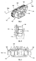
- FIG. 1 A perspective view of a winch apparatus, generally identified by reference numeral 10, in accordance with an embodiment of the present invention is shown in Figure 1 .
- the winch apparatus 10 is configured as a capstan type winch for use in operation with a spoolable medium, such as a metal or synthetic wire, rope, cable or the like.
- the winch apparatus 10 comprises first and second drum assemblies 12, 14 mounted on a common support shaft 16 which is secured to a frame 18.
- the first drum assembly 12 comprises a plurality of circumferentially arranged support elements 20 each having discrete contact surfaces which collectively define a drum contact surface of the first drum assembly 12.
- the support elements 20 are arranged with gaps defined therebetween, such that a discontinuous drum support surface is established.
- the second drum assembly 14 also comprises a plurality of circumferentially arranged support elements 22 having individual discrete contact surfaces which collectively define a drum contact surface of the second drum assembly 14.
- the support elements 22 are also arranged with gaps therebetween, such that a discontinuous drum contact surface is established.
- the drum assemblies 12, 14 are arranged such that the respective support elements 20, 22 are intermeshed. That is, the support elements 20 of the first drum assembly 12 are arranged in the gaps defined between the support elements 22 of the second drum assembly 14, and vice versa. Accordingly, the first and second drum assemblies 12, 14 may be arranged to overlap in both axial and radial
- FIG. 2 provides a simplified and diagrammatic illustration of the first and second drum assemblies 12, 14, shown separated for clarity.
- Each drum assembly 12, 14 is provided generally in the form of a cylindrical cage, with the respective support elements 20, 22 arranged circumferentially around respective first and second axes of rotation 24, 26.
- Each support element 20, 22 is arranged parallel with a respective axis of rotation 24, 26 such that the defined discontinuous drum contact surface of each drum assembly 12, 14 is also arranged parallel with a respective rotation axis 24, 26.
- Each support element 22, 24 is generally elongate with opposite ends of each support element 22, 24 secured via mechanical fasteners 27 to the outer periphery of respective inner support members 28, 30 and respective outer support members 32, 34.
- each drum assembly 12, 14 comprises a slewing gear ring 40, 42 configured to be engaged by a drive arrangement comprising multiple individual drive assemblies 44 (see Figure 1 ).
- a single drive assembly may be provided.
- the drive arrangement is configured to rotate each drum assembly 12, 14 about the respective rotation axes 24, 26 in a synchronous manner.
- the drive arrangement may be electric, hydraulic, pneumatic, engine or the like, or any suitable combination thereof.
- FIG 3 shows the simplified drum assemblies 12, 14 of Figure 2 intermeshed to define the complete winch apparatus 10.
- the drum assemblies 12, 14 are arranged such that the first and second axes of rotation 24, 26 are inclined relative to each other, which results in the discontinuous contact surfaces of each drum assembly 12, 24 also being inclined relative to each other.
- the angle of inclination has been exaggerated for purposes of the present description.
- this inclined arrangement of the first and second drum assemblies 12, 14 establishes a preferential path of an associated spoolable medium wrapped around the winch apparatus 10.
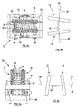
- FIG. 4 wherein Figure 4a shows the winch apparatus 10 from above, and Figure 4b provides a simplified illustration of the relative inclination which demonstrates a relative inclination between the axes of rotation 24, 26, with the relative inclination exaggerated for clarity.
- the drum assemblies 12, 14 are transversely skewed relative to a vertical plane 45 such that the first and second rotation axes 24, 26 define a relative inclination angle ⁇ V .
- inclination angle ⁇ V may be in a region between 1 to 3 degrees, for example around 1.8 degrees.
- the individual drive assemblies 44 are also clearly illustrated in Figure 4a , wherein each drum 14, 16 is engaged to be drive by two of the drive assemblies 44. Further, each drive assembly 44 is mounted on the frame 18 in a manner to accommodate the relative inclination of each drum assembly 12, 14.
- FIG. 5a shows the winch apparatus 10 from the front
- Figure 5b provides a simplified illustration of the relative inclination which demonstrates a relative inclination between the axes of rotation 24, 26, with the relative inclination exaggerated for clarity.
- the drum assemblies 12, 14 are also transversely skewed relative to a horizontal plane 46 such that the first and second rotation axes 24, 26 define an relative inclination angle ⁇ H
- inclination angle ⁇ H may be in a region between 1 to 3 degrees, for example around 1.8 degrees.
- both the first and second drum assemblies 12, 14 are rotatably mounted on the common support shaft 16.
- the support shaft may include offset portions configured to permit rotation of each drum assembly 12, 14 about the first and second inclined rotation axes.
- a spoolable medium 50 such as a synthetic or fibre rope, such as a BOB (Braid Optimised for Bending) rope.
- the spoolable medium 50 is wrapped a number of times around each drum assembly 12, 14 with an outboard end 50a extending from one side of the winch assembly 10, specifically from a defined outboard take-off point 52, and an inboard end 50b extending from the opposite side of the winch assembly 10, specifically from a defined inboard take-off point 54.
- the outboard end 50a of the spoolable medium 50 may extend to engage a payload, and the inboard end 50b may extend to a storage location.
- the spoolable medium 50 follows a defined helical path around each drum assembly 12, 14 between the defined take-off points 52, 54.
- the defined helical path and take-off points 52, 54 of the spoolable medium are established and fixed by the relative inclination of each drum assembly 12, 14. Accordingly, the requirement for any specific fleeting arrangements, such as knives or the like, is eliminated.
- the winch apparatus 10 is configured to apply a tension gradient along the portion of the spoolable medium 50 in contact with the contact surfaces of the drum assemblies 12, 14. Specifically, the apparatus 10 creates a tension gradient which reduces the tension in the spoolable medium from a high tension T1 in the outboard end 50a to a low tension T2 in the inboard end 50b.
- This tension gradient may be used to permit appropriate manipulation of a payload attached to the spoolable medium 50.
- the relative inclination of the drum assemblies 12, 14 is such that for a single wrap of the spoolable medium 50, half of the spoolable medium is engaged only by the support elements 20 of the first drum assembly 12, and the other half of the spoolable medium is engaged only by the support elements 22 of the second drum assembly 14.
- each drum assembly 12, 14 comprises a discontinuous contact surface provided by the spaced apart respective support elements 22, 24. Accordingly, each support element provides a discrete contribution to the total tension gradient applied across the spoolable medium, as will be described with reference to Figure 7 which shows a cross-sectional view of a single support element 20.
- the support element 20 includes a curved surface 56 defined by a circular arc which extends for an arc angle ⁇ E defined by the central angle formed by the end points 58, 60 of the arc surface 56. It should be noted that the drum contact surface wrap angle defined by the support elements in each drum assembly 12, 14 totals 360 degrees.
- This arrangement may permit a preferential support of the spoolable medium 50 over the collective drum contact surfaces, which may prevent any kinking or the like of the spoolable medium 50 across any edge regions of the support elements 20, 22.
- This arrangement may also permit a preferential support of the spoolable medium 50 to be permitted while achieving a maximum tension gradient within the spoolable medium 50 by maximising the available wrap angle.
- the provision of the total tension gradient in individual discrete portions over the separate support elements 20, 22 may permit more control over the tension gradient in the spoolable medium 50. Furthermore, this arrangement may permit a required tension gradient to be ensured over a minimum length of the spoolable medium 50. Accordingly, high resolution de-tensioning may be achieved by applying many small points of contact providing a proportionally small variance in tension differential. Thus, changes in length, relative movement, work and the like are minimised to mitigate frictional heat generated in the spoolable medium 50. Tension may therefore be removed or added in many small accurately controlled linear steps as opposed to a low quantity of large steps as present in prior art systems. This arrangement provides a kind method of working the spoolable medium 50 to provide longer life and operate the spoolable medium 50 in its natural form without applying excessive external forces.
- Figure 8 shows a number of adjacent support elements 20 in cross-section, engaged with the spoolable medium 50.
- the facing edges of the arc shaped surfaces of adjacent elements 20 are arranged tangentially to each other. This arrangement permits the spoolable medium to extend tangentially between adjacent support elements 20, thus achieving complete contact with each individual surface 56 and preventing any adverse kinking or the like of the spoolable medium as it leaves one support element and arrives at an adjacent support element.
- Figure 8 also clearly illustrates the gap arrangement between adjacent support elements 20.
- This gap arrangement provides the respective discontinuous drum contact surfaces.
- providing the support elements with gaps therebetween permits the support elements to be positioned to define a desired effective drum radius 62, for example which is appropriate to the particular spoolable medium 50, and at the same time provide the necessary overall wrap angle to achieve a suitable tension gradient while minimising the actual contact surface area.
- the provision of gaps between support elements may provide advantages in terms of cooling, drainage and the like.
- each drum assembly 12, 14 comprises an associated braking arrangement 13, 15 configured to providing friction braking to the drum assemblies 12, 14.
- the drive assemblies 44 may alternatively, or additionally, be configured to provide braking.
- winch apparatus not forming part of the invention will now be described with reference to Figures 9, 10 and 11 .
- the winch apparatus generally identified by reference numeral 110, is similar to the apparatus 10 first shown in Figure 1 and as such like features share like reference numerals, incremented by 100.
- the apparatus 110 comprises first and second drum assemblies 112, 114 which are mounted on a frame 118 and arranged to be separated in a radial direction, and to overlap in an axial direction.
- Each drum assembly 112, 114 is arranged to be engaged by a spoolable medium 150 to establish an outboard end 150a at a high tension T1, and an inboard end 150b at a lower tension T2.
- the first and second drum assemblies 112, 114 are mounted on the frame 118 to be inclined relative to each other. This relative inclination arrangement permits the spoolable medium 150 to follow a set and predefined helical path around each drum assembly 112, 114, and also to set the respective outboard and inboard take-off points 152, 154.
- each drum assembly 112, 114 comprises a respective set of circumferentially arranged support elements 120, 122 which define gaps therebetween, wherein the support elements 120, 122 collectively define discontinuous drum contact surfaces of each drum assembly 112, 114.
- the apparatuses 10, 110 may be used in onshore applications, for example in crane arrangements or the like. Further, the apparatuses 10, 110 may be used in marine environments, for example in offshore vessels, such as ships, oil rigs or the like. For example, the apparatuses 10, 110 may be used in applications for deploying and retrieving payloads to and from the sea.
- the apparatuses 10, 110 may also be used in combination with further equipment suited for the appropriate use.
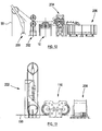
- An example of such a combination of equipment is shown in Figure 12 , reference to which is now made.
- the exemplary arrangement of Figure 12 reflects an offshore application and includes the winch apparatus 10 first shown in Figure 1 .
- the arrangement includes an overboarding assembly 200 which is used to appropriately direct a spoolable medium 50 (shown in broken outline) from a vessel (not shown) into the sea.
- a heave compensator 202 is provided which provides dynamic compensation to the spoolable medium 50 to accommodate for heaving motion of the associated vessel.
- the arrangement of Figure 12 includes a track tensioner arrangement 204 which is configured to apply a degree of tension to an inboard side of the spoolable medium which extends from the winch apparatus 10.
- the track tensioner 204 may be used to apply a desired inboard tension in the spoolable medium 50 which permits an appropriate outboard tension to be accommodated, for example.
- the arrangement shown in Figure 12 further includes a storage arrangement in the form of a storage basket 206 which permits the spoolable medium to be stored in a zero tension state.
- the arrangement in Figure 13 also reflects an offshore application and in this example includes the winch apparatus 110 first shown in Figure 9 and not forming part of the invention.
- the arrangement shown may include the same components as those of Figure 13 , such as the heave compensator 202.
- the inboard end of the spoolable medium 150 is spooled to and from a winch drum 208, which may provide storage for the spoolable medium 150, and also establish a required degree of tension within the inboard end of the spoolable medium.
Landscapes
- Engineering & Computer Science (AREA)
- Mechanical Engineering (AREA)
- Earth Drilling (AREA)
- Storing, Repeated Paying-Out, And Re-Storing Of Elongated Articles (AREA)
- Rolls And Other Rotary Bodies (AREA)
- Storage Of Web-Like Or Filamentary Materials (AREA)
- Press Drives And Press Lines (AREA)
- Preliminary Treatment Of Fibers (AREA)
- Wind Motors (AREA)
- Conveying And Assembling Of Building Elements In Situ (AREA)
Claims (15)
- Windenvorrichtung (10), die eine erste und zweite Trommelanordnung (12, 14) aufweist, wobei eine jede eine diskontinuierliche Trommelkontaktfläche für einen Eingriff mit einem gemeinsamen spulbaren Medium (50) definiert, dadurch gekennzeichnet, dass die erste und zweite Trommelanordnung (12, 14) miteinander in Eingriff kommen und angeordnet sind, um sich um eine jeweilige erste und zweite Rotationsachse (24, 26) zu drehen, die relativ zueinander geneigt sind.
- Windenvorrichtung (10) nach Anspruch 1, bei der die erste und zweite Rotationsachse (24, 26) relativ zueinander in zwei Bezugsebenen geneigt sind, wobei die zwei Bezugsebenen wahlweise zueinander senkrecht stehen.
- Windenvorrichtung (10) nach einem der vorhergehenden Ansprüche, bei der eine jede Trommelkontaktfläche im Allgemeinen parallel zu einer dazugehörenden Rotationsachse (24, 26) der Trommel ausgerichtet ist, so dass die Trommelkontaktflächen der jeweiligen ersten und zweiten Trommelanordnung (12, 14) ebenfalls relativ zueinander in dem gleichen Maß geneigt sind wie die erste und die zweite Rotationsachse (24, 26).
- Windenvorrichtung (10) nach einem der vorhergehenden Ansprüche, bei der die erste und zweite Trommelanordnung (12, 14) ausgebildet sind, um mit einem gewickelten Zwischenabschnitt eines spulbaren Mediums (50) in Eingriff zu kommen, so dass sich die Endabschnitte des spulbaren Mediums (50) auf beiden Seiten des dazwischen liegenden gewickelten Abschnittes nach außen von der Windenvorrichtung (10) erstrecken, um einen außen liegenden Endabschnitt (50a) und einen innen liegenden Endabschnitt (50b) zu definieren.
- Windenvorrichtung (10) nach einem der vorhergehenden Ansprüche, bei der die relativ geneigte Ausrichtung der ersten und zweiten Rotationsachse (24, 26) der Trommelanordnungen (12, 14) angeordnet ist, um zu gestatten, dass die jeweiligen Trommelkontaktflächen zusammenwirken, um ein dazugehörendes spulbares Medium (50) so zu manipulieren, dass es einem vorher definierten spiralförmigen Weg folgt.
- Windenvorrichtung (10) nach einem der vorhergehenden Ansprüche, bei der der Winkel der relativen Neigung der ersten und zweiten Rotationsachse (24, 26) unveränderlich ist.
- Windenvorrichtung (10) nach einem der Ansprüche 1 bis 5, bei der der Winkel der relativen Neigung regulierbar ist.
- Windenvorrichtung (10) nach einem der vorhergehenden Ansprüche, bei der der Winkel der relativen Neigung der ersten und zweiten Rotationsachse (24, 26) im Bereich von 1 bis 3 Grad liegt.
- Windenvorrichtung (10) nach einem der vorhergehenden Ansprüche, bei der eine jede Trommelanordnung (12, 14) eine Vielzahl von Stützelementen (20, 22) aufweist, die peripher um eine jeweilige Rotationsachse (24, 26) der Trommelanordnungen (12, 14) angeordnet sind, um die jeweiligen Trommelkontaktflächen zusammen zu definieren.
- Windenvorrichtung (10) nach Anspruch 9, bei der ein jedes Stützelement (20, 22) eine einzelne Auflagefläche (56) aufweist, die angeordnet ist, um einen einzelnen Abschnitt einer jeweiligen Trommelkontaktfläche zu definieren.
- Windenvorrichtung (10) nach Anspruch 10, bei der die einzelne Auflagefläche (56) des einen oder der mehreren Stützelemente (20, 22) eine Bogenform definiert, und bei der wahlweise gegenüberliegende Ränder (58, 60) der benachbarten bogenförmigen Flächen tangential zueinander angeordnet sind.
- Windenvorrichtung (10) nach Anspruch 10 oder 11, bei der die Stützelemente (20, 22) relativ zueinander angeordnet sind, um eine diskontinuierliche Trommelkontaktfläche zu bilden, wobei die benachbarten Stützelemente (20, 22) voneinander beabstandet sind, um eine Lücke dazwischen zu definieren.
- Windenvorrichtung (10) nach Anspruch 12, bei der die Stützelemente (20, 22) einer jeden Trommelanordnung (12, 14) ineinander geschachtelt sind, so dass die Stützelemente (20, 22) der einen Trommelanordnung (12, 14) in den Lücken zwischen den Stützelementen (20, 22) auf der anderen Trommelanordnung (12, 14) positioniert sind.
- Windenvorrichtung (10) nach einem der vorhergehenden Ansprüche, bei der die Oberfläche einer oder beider der Trommelkontaktflächen so ausgebildet ist, dass der Reibungskoeffizient zwischen den jeweiligen Oberflächen und einem spulbaren Medium (50) kleiner ist als der Reibungskoeffizient zwischen den einzelnen Komponenten des spulbaren Mediums (50).
- Verfahren zum Herstellen eines Spannungsgefälles innerhalb eines spulbaren Mediums (50), das die folgenden Schritte aufweist:Bereitstellen einer ersten und zweiten Trommelanordnung (12, 14), die jeweils eine diskontinuierliche Trommelkontaktfläche definieren, wobei die erste und die zweite Trommelanordnung (12, 14) miteinander in Eingriff kommen;Wickeln eines Teils des spulbaren Mediums (50) um die Kontaktfläche von sowohl der ersten als auch der zweiten Trommelanordnung (12, 14); undDrehen sowohl der ersten als auch der zweiten Trommelanordnung (12, 14) um die jeweilige erste und zweite Rotationsachse (24, 26), die relativ zueinander geneigt sind.
Priority Applications (1)
| Application Number | Priority Date | Filing Date | Title |
|---|---|---|---|
| PL11710539T PL2521685T3 (pl) | 2010-03-27 | 2011-03-17 | Aparat wyciągarki |
Applications Claiming Priority (2)
| Application Number | Priority Date | Filing Date | Title |
|---|---|---|---|
| GBGB1005200.9A GB201005200D0 (en) | 2010-03-27 | 2010-03-27 | Winch apparatus |
| PCT/GB2011/000373 WO2011121272A1 (en) | 2010-03-27 | 2011-03-17 | Winch apparatus |
Publications (2)
| Publication Number | Publication Date |
|---|---|
| EP2521685A1 EP2521685A1 (de) | 2012-11-14 |
| EP2521685B1 true EP2521685B1 (de) | 2016-01-27 |
Family
ID=42228482
Family Applications (1)
| Application Number | Title | Priority Date | Filing Date |
|---|---|---|---|
| EP11710539.5A Active EP2521685B1 (de) | 2010-03-27 | 2011-03-17 | Windenvorrichtung |
Country Status (12)
| Country | Link |
|---|---|
| US (1) | US8814143B2 (de) |
| EP (1) | EP2521685B1 (de) |
| AU (1) | AU2011234316B2 (de) |
| BR (1) | BR112012022463B1 (de) |
| CA (1) | CA2794326C (de) |
| DK (1) | DK2521685T3 (de) |
| ES (1) | ES2567717T3 (de) |
| GB (1) | GB201005200D0 (de) |
| NZ (1) | NZ601286A (de) |
| PL (1) | PL2521685T3 (de) |
| SG (1) | SG182829A1 (de) |
| WO (1) | WO2011121272A1 (de) |
Cited By (1)
| Publication number | Priority date | Publication date | Assignee | Title |
|---|---|---|---|---|
| CN111587216A (zh) * | 2018-01-16 | 2020-08-25 | 神钢建机株式会社 | 卷扬机卷筒及具备该卷扬机卷筒的起重机 |
Families Citing this family (9)
| Publication number | Priority date | Publication date | Assignee | Title |
|---|---|---|---|---|
| NL2004908C2 (en) * | 2010-06-17 | 2011-12-20 | Itrec Bv | Double drum traction winch. |
| GB201306974D0 (en) * | 2013-04-17 | 2013-05-29 | Parkburn Prec Handling Systems Ltd | Load Bearing Apparatus and Method |
| ITTO20130322A1 (it) | 2013-04-22 | 2013-07-22 | Kite Gen Res Srl | Puleggia perfezionata per verricello ad alta efficienza. |
| ITTO20130323A1 (it) | 2013-04-22 | 2013-07-22 | Kite Gen Res Srl | Puleggia perfezionata per verricello ad alta efficienza. |
| AT515335A1 (de) | 2014-01-30 | 2015-08-15 | Teufelberger Fiber Rope Gmbh | Seilverbund |
| JP6391004B2 (ja) * | 2014-09-03 | 2018-09-19 | パナソニックIpマネジメント株式会社 | 水耕栽培装置 |
| US9950915B2 (en) * | 2015-05-27 | 2018-04-24 | Rt Ltd. | Winch system |
| CN111732016A (zh) * | 2020-06-04 | 2020-10-02 | 东营胜滋自动化科技有限责任公司 | 模块化组装的绞车卷筒及绞车 |
| US11987479B2 (en) | 2021-04-05 | 2024-05-21 | Goodrich Corporation | Cable tensioning capstan assembly with independently rotatable flange |
Family Cites Families (13)
| Publication number | Priority date | Publication date | Assignee | Title |
|---|---|---|---|---|
| GB142016A (en) | 1919-09-11 | 1920-04-29 | Daniel Kops | Improvements in apparel corsets |
| FR1105165A (fr) * | 1952-10-17 | 1955-11-28 | Entpr S Soc Gen | Perfectionnements aux treuils |
| SU459423A1 (ru) | 1972-03-10 | 1975-02-05 | Центральное Конструкторское Бюро Тяжелого Машиностроения | Барабан дл многослойной навивки каната |
| GB1425016A (en) | 1972-10-24 | 1976-02-18 | Donkin Co Ltd | Winch arrangement |
| US4204664A (en) * | 1976-09-09 | 1980-05-27 | Pyramid Manufacturing Company | Winch mechanism for crane |
| GB2009077A (en) | 1977-12-05 | 1979-06-13 | Pyramid Mfg Co | Winch Mechanism for Crane |
| SU1306896A1 (ru) | 1985-09-16 | 1987-04-30 | Институт Геотехнической Механики Ан Усср | Футеровка канатного барабана |
| US5217176A (en) | 1991-03-21 | 1993-06-08 | Texaco Inc. | Apparatus for providing strain relief during retrieving of marine seismic cables |
| US5779226A (en) * | 1996-03-15 | 1998-07-14 | Wudtke; Donald J. | Anchoring system |
| NO324416B1 (no) * | 1998-04-21 | 2007-10-08 | Odim Asa | Flerskaren tractionvinsj |
| NO983774L (no) | 1998-08-18 | 2000-02-21 | Rapp Hydema As | Trekkvinsj |
| HRPK990078B3 (en) | 1999-03-10 | 2005-04-30 | Zelić Marko | Pass-through universal automatic winch |
| FR2843953B1 (fr) * | 2002-08-28 | 2005-04-08 | Kley France | Treuil du type a cabestan |
-
2010
- 2010-03-27 GB GBGB1005200.9A patent/GB201005200D0/en not_active Ceased
-
2011
- 2011-03-17 AU AU2011234316A patent/AU2011234316B2/en active Active
- 2011-03-17 EP EP11710539.5A patent/EP2521685B1/de active Active
- 2011-03-17 NZ NZ601286A patent/NZ601286A/en unknown
- 2011-03-17 DK DK11710539.5T patent/DK2521685T3/en active
- 2011-03-17 ES ES11710539.5T patent/ES2567717T3/es active Active
- 2011-03-17 CA CA2794326A patent/CA2794326C/en active Active
- 2011-03-17 BR BR112012022463-8A patent/BR112012022463B1/pt active IP Right Grant
- 2011-03-17 SG SG2012056867A patent/SG182829A1/en unknown
- 2011-03-17 WO PCT/GB2011/000373 patent/WO2011121272A1/en not_active Ceased
- 2011-03-17 PL PL11710539T patent/PL2521685T3/pl unknown
- 2011-03-17 US US13/637,482 patent/US8814143B2/en active Active
Cited By (3)
| Publication number | Priority date | Publication date | Assignee | Title |
|---|---|---|---|---|
| CN111587216A (zh) * | 2018-01-16 | 2020-08-25 | 神钢建机株式会社 | 卷扬机卷筒及具备该卷扬机卷筒的起重机 |
| CN111587216B (zh) * | 2018-01-16 | 2021-10-26 | 神钢建机株式会社 | 卷扬机卷筒及具备该卷扬机卷筒的起重机 |
| US11247880B2 (en) | 2018-01-16 | 2022-02-15 | Kobelco Construction Machinery Co., Ltd. | Winch drum and crane provided therewith |
Also Published As
| Publication number | Publication date |
|---|---|
| CA2794326A1 (en) | 2011-10-06 |
| BR112012022463B1 (pt) | 2021-02-23 |
| GB201005200D0 (en) | 2010-05-12 |
| AU2011234316A1 (en) | 2012-08-09 |
| DK2521685T3 (en) | 2016-05-02 |
| US8814143B2 (en) | 2014-08-26 |
| SG182829A1 (en) | 2012-08-30 |
| PL2521685T3 (pl) | 2016-08-31 |
| WO2011121272A1 (en) | 2011-10-06 |
| CA2794326C (en) | 2018-03-13 |
| AU2011234316B2 (en) | 2015-04-23 |
| ES2567717T3 (es) | 2016-04-26 |
| BR112012022463A2 (pt) | 2016-07-12 |
| EP2521685A1 (de) | 2012-11-14 |
| NZ601286A (en) | 2014-10-31 |
| US20130020544A1 (en) | 2013-01-24 |
Similar Documents
| Publication | Publication Date | Title |
|---|---|---|
| US8814143B2 (en) | Inclined drum arrangement for winch apparatus | |
| US8322691B2 (en) | Winch for pulling cables, in particular synthetic cables used offshore | |
| US9850112B2 (en) | Load bearing apparatus and method | |
| EP2688832B2 (de) | Vorrichtung zum spannen eines seils | |
| EP3183201B1 (de) | Windenanordnung und verfahren zur verwendung | |
| CN108463421B (zh) | 用于在绞车滚筒上卷绕绳索的系统和卷绕装置 | |
| CN103459299A (zh) | 张紧设备 | |
| US20130193689A1 (en) | Apparatus for Guiding a Flexible Member | |
| US7766307B2 (en) | Cable handling device | |
| KR101887346B1 (ko) | 세장형 물품에 대한 지지 장치 | |
| AU2008293102B2 (en) | Axial displacement device, line deployment system, and a method for deploying a line | |
| EP2703331B1 (de) | Traktionssystem unter Verwendung eines mehrsehnigen Kabels mit einem Ablenkungswinkel | |
| US10875747B2 (en) | Wire back tension device | |
| NO177383B (no) | Spill for ömfintlige kabler | |
| EP2980003A1 (de) | Winde mit einer Kabelführungseinrichtung | |
| Matejic et al. | Tribological aspects of the process of winding the steel rope around the winch drum | |
| HK1215563B (en) | Load bearing apparatus and method | |
| EP2872439B1 (de) | Schiffswindenanordnung |
Legal Events
| Date | Code | Title | Description |
|---|---|---|---|
| PUAI | Public reference made under article 153(3) epc to a published international application that has entered the european phase |
Free format text: ORIGINAL CODE: 0009012 |
|
| 17P | Request for examination filed |
Effective date: 20120712 |
|
| AK | Designated contracting states |
Kind code of ref document: A1 Designated state(s): AL AT BE BG CH CY CZ DE DK EE ES FI FR GB GR HR HU IE IS IT LI LT LU LV MC MK MT NL NO PL PT RO RS SE SI SK SM TR |
|
| DAX | Request for extension of the european patent (deleted) | ||
| 17Q | First examination report despatched |
Effective date: 20140911 |
|
| GRAP | Despatch of communication of intention to grant a patent |
Free format text: ORIGINAL CODE: EPIDOSNIGR1 |
|
| INTG | Intention to grant announced |
Effective date: 20150721 |
|
| GRAS | Grant fee paid |
Free format text: ORIGINAL CODE: EPIDOSNIGR3 |
|
| GRAA | (expected) grant |
Free format text: ORIGINAL CODE: 0009210 |
|
| AK | Designated contracting states |
Kind code of ref document: B1 Designated state(s): AL AT BE BG CH CY CZ DE DK EE ES FI FR GB GR HR HU IE IS IT LI LT LU LV MC MK MT NL NO PL PT RO RS SE SI SK SM TR |
|
| REG | Reference to a national code |
Ref country code: GB Ref legal event code: FG4D |
|
| REG | Reference to a national code |
Ref country code: CH Ref legal event code: EP |
|
| REG | Reference to a national code |
Ref country code: AT Ref legal event code: REF Ref document number: 772587 Country of ref document: AT Kind code of ref document: T Effective date: 20160215 |
|
| REG | Reference to a national code |
Ref country code: IE Ref legal event code: FG4D |
|
| REG | Reference to a national code |
Ref country code: DE Ref legal event code: R096 Ref document number: 602011022995 Country of ref document: DE |
|
| REG | Reference to a national code |
Ref country code: FR Ref legal event code: PLFP Year of fee payment: 6 |
|
| REG | Reference to a national code |
Ref country code: PT Ref legal event code: SC4A Free format text: AVAILABILITY OF NATIONAL TRANSLATION Effective date: 20160412 Ref country code: RO Ref legal event code: EPE |
|
| REG | Reference to a national code |
Ref country code: ES Ref legal event code: FG2A Ref document number: 2567717 Country of ref document: ES Kind code of ref document: T3 Effective date: 20160426 |
|
| REG | Reference to a national code |
Ref country code: DK Ref legal event code: T3 Effective date: 20160426 |
|
| REG | Reference to a national code |
Ref country code: SE Ref legal event code: TRGR |
|
| REG | Reference to a national code |
Ref country code: NL Ref legal event code: FP |
|
| REG | Reference to a national code |
Ref country code: LT Ref legal event code: MG4D |
|
| REG | Reference to a national code |
Ref country code: AT Ref legal event code: MK05 Ref document number: 772587 Country of ref document: AT Kind code of ref document: T Effective date: 20160127 |
|
| REG | Reference to a national code |
Ref country code: NO Ref legal event code: T2 Effective date: 20160127 |
|
| PG25 | Lapsed in a contracting state [announced via postgrant information from national office to epo] |
Ref country code: GR Free format text: LAPSE BECAUSE OF FAILURE TO SUBMIT A TRANSLATION OF THE DESCRIPTION OR TO PAY THE FEE WITHIN THE PRESCRIBED TIME-LIMIT Effective date: 20160428 Ref country code: HR Free format text: LAPSE BECAUSE OF FAILURE TO SUBMIT A TRANSLATION OF THE DESCRIPTION OR TO PAY THE FEE WITHIN THE PRESCRIBED TIME-LIMIT Effective date: 20160127 |
|
| PG25 | Lapsed in a contracting state [announced via postgrant information from national office to epo] |
Ref country code: AT Free format text: LAPSE BECAUSE OF FAILURE TO SUBMIT A TRANSLATION OF THE DESCRIPTION OR TO PAY THE FEE WITHIN THE PRESCRIBED TIME-LIMIT Effective date: 20160127 Ref country code: IS Free format text: LAPSE BECAUSE OF FAILURE TO SUBMIT A TRANSLATION OF THE DESCRIPTION OR TO PAY THE FEE WITHIN THE PRESCRIBED TIME-LIMIT Effective date: 20160527 Ref country code: RS Free format text: LAPSE BECAUSE OF FAILURE TO SUBMIT A TRANSLATION OF THE DESCRIPTION OR TO PAY THE FEE WITHIN THE PRESCRIBED TIME-LIMIT Effective date: 20160127 Ref country code: LT Free format text: LAPSE BECAUSE OF FAILURE TO SUBMIT A TRANSLATION OF THE DESCRIPTION OR TO PAY THE FEE WITHIN THE PRESCRIBED TIME-LIMIT Effective date: 20160127 Ref country code: LV Free format text: LAPSE BECAUSE OF FAILURE TO SUBMIT A TRANSLATION OF THE DESCRIPTION OR TO PAY THE FEE WITHIN THE PRESCRIBED TIME-LIMIT Effective date: 20160127 |
|
| REG | Reference to a national code |
Ref country code: DE Ref legal event code: R097 Ref document number: 602011022995 Country of ref document: DE |
|
| PG25 | Lapsed in a contracting state [announced via postgrant information from national office to epo] |
Ref country code: EE Free format text: LAPSE BECAUSE OF FAILURE TO SUBMIT A TRANSLATION OF THE DESCRIPTION OR TO PAY THE FEE WITHIN THE PRESCRIBED TIME-LIMIT Effective date: 20160127 Ref country code: MC Free format text: LAPSE BECAUSE OF FAILURE TO SUBMIT A TRANSLATION OF THE DESCRIPTION OR TO PAY THE FEE WITHIN THE PRESCRIBED TIME-LIMIT Effective date: 20160127 Ref country code: LU Free format text: LAPSE BECAUSE OF FAILURE TO SUBMIT A TRANSLATION OF THE DESCRIPTION OR TO PAY THE FEE WITHIN THE PRESCRIBED TIME-LIMIT Effective date: 20160317 |
|
| REG | Reference to a national code |
Ref country code: CH Ref legal event code: PL |
|
| PG25 | Lapsed in a contracting state [announced via postgrant information from national office to epo] |
Ref country code: SM Free format text: LAPSE BECAUSE OF FAILURE TO SUBMIT A TRANSLATION OF THE DESCRIPTION OR TO PAY THE FEE WITHIN THE PRESCRIBED TIME-LIMIT Effective date: 20160127 Ref country code: SK Free format text: LAPSE BECAUSE OF FAILURE TO SUBMIT A TRANSLATION OF THE DESCRIPTION OR TO PAY THE FEE WITHIN THE PRESCRIBED TIME-LIMIT Effective date: 20160127 |
|
| PLBE | No opposition filed within time limit |
Free format text: ORIGINAL CODE: 0009261 |
|
| STAA | Information on the status of an ep patent application or granted ep patent |
Free format text: STATUS: NO OPPOSITION FILED WITHIN TIME LIMIT |
|
| REG | Reference to a national code |
Ref country code: IE Ref legal event code: MM4A |
|
| 26N | No opposition filed |
Effective date: 20161028 |
|
| PG25 | Lapsed in a contracting state [announced via postgrant information from national office to epo] |
Ref country code: IE Free format text: LAPSE BECAUSE OF NON-PAYMENT OF DUE FEES Effective date: 20160317 Ref country code: CH Free format text: LAPSE BECAUSE OF NON-PAYMENT OF DUE FEES Effective date: 20160331 Ref country code: LI Free format text: LAPSE BECAUSE OF NON-PAYMENT OF DUE FEES Effective date: 20160331 |
|
| REG | Reference to a national code |
Ref country code: FR Ref legal event code: PLFP Year of fee payment: 7 |
|
| PG25 | Lapsed in a contracting state [announced via postgrant information from national office to epo] |
Ref country code: SI Free format text: LAPSE BECAUSE OF FAILURE TO SUBMIT A TRANSLATION OF THE DESCRIPTION OR TO PAY THE FEE WITHIN THE PRESCRIBED TIME-LIMIT Effective date: 20160127 Ref country code: BG Free format text: LAPSE BECAUSE OF FAILURE TO SUBMIT A TRANSLATION OF THE DESCRIPTION OR TO PAY THE FEE WITHIN THE PRESCRIBED TIME-LIMIT Effective date: 20160427 |
|
| PG25 | Lapsed in a contracting state [announced via postgrant information from national office to epo] |
Ref country code: MT Free format text: LAPSE BECAUSE OF FAILURE TO SUBMIT A TRANSLATION OF THE DESCRIPTION OR TO PAY THE FEE WITHIN THE PRESCRIBED TIME-LIMIT Effective date: 20160127 |
|
| REG | Reference to a national code |
Ref country code: FR Ref legal event code: PLFP Year of fee payment: 8 |
|
| PG25 | Lapsed in a contracting state [announced via postgrant information from national office to epo] |
Ref country code: CY Free format text: LAPSE BECAUSE OF FAILURE TO SUBMIT A TRANSLATION OF THE DESCRIPTION OR TO PAY THE FEE WITHIN THE PRESCRIBED TIME-LIMIT Effective date: 20160127 Ref country code: HU Free format text: LAPSE BECAUSE OF FAILURE TO SUBMIT A TRANSLATION OF THE DESCRIPTION OR TO PAY THE FEE WITHIN THE PRESCRIBED TIME-LIMIT; INVALID AB INITIO Effective date: 20110317 |
|
| PG25 | Lapsed in a contracting state [announced via postgrant information from national office to epo] |
Ref country code: MK Free format text: LAPSE BECAUSE OF FAILURE TO SUBMIT A TRANSLATION OF THE DESCRIPTION OR TO PAY THE FEE WITHIN THE PRESCRIBED TIME-LIMIT Effective date: 20160127 Ref country code: MT Free format text: LAPSE BECAUSE OF FAILURE TO SUBMIT A TRANSLATION OF THE DESCRIPTION OR TO PAY THE FEE WITHIN THE PRESCRIBED TIME-LIMIT Effective date: 20160331 Ref country code: TR Free format text: LAPSE BECAUSE OF FAILURE TO SUBMIT A TRANSLATION OF THE DESCRIPTION OR TO PAY THE FEE WITHIN THE PRESCRIBED TIME-LIMIT Effective date: 20160127 |
|
| PG25 | Lapsed in a contracting state [announced via postgrant information from national office to epo] |
Ref country code: AL Free format text: LAPSE BECAUSE OF FAILURE TO SUBMIT A TRANSLATION OF THE DESCRIPTION OR TO PAY THE FEE WITHIN THE PRESCRIBED TIME-LIMIT Effective date: 20160127 |
|
| P01 | Opt-out of the competence of the unified patent court (upc) registered |
Effective date: 20230526 |
|
| PGFP | Annual fee paid to national office [announced via postgrant information from national office to epo] |
Ref country code: ES Payment date: 20250604 Year of fee payment: 15 |
|
| PGFP | Annual fee paid to national office [announced via postgrant information from national office to epo] |
Ref country code: IT Payment date: 20250317 Year of fee payment: 15 |
|
| PGFP | Annual fee paid to national office [announced via postgrant information from national office to epo] |
Ref country code: SE Payment date: 20260304 Year of fee payment: 16 |
|
| PGFP | Annual fee paid to national office [announced via postgrant information from national office to epo] |
Ref country code: GB Payment date: 20260310 Year of fee payment: 16 |
|
| PGFP | Annual fee paid to national office [announced via postgrant information from national office to epo] |
Ref country code: DE Payment date: 20260304 Year of fee payment: 16 Ref country code: DK Payment date: 20260304 Year of fee payment: 16 Ref country code: NO Payment date: 20260317 Year of fee payment: 16 |
|
| PGFP | Annual fee paid to national office [announced via postgrant information from national office to epo] |
Ref country code: BE Payment date: 20260309 Year of fee payment: 16 Ref country code: RO Payment date: 20260219 Year of fee payment: 16 Ref country code: FI Payment date: 20260318 Year of fee payment: 16 |
|
| PGFP | Annual fee paid to national office [announced via postgrant information from national office to epo] |
Ref country code: NL Payment date: 20260309 Year of fee payment: 16 |
|
| PGFP | Annual fee paid to national office [announced via postgrant information from national office to epo] |
Ref country code: FR Payment date: 20260312 Year of fee payment: 16 |
|
| PGFP | Annual fee paid to national office [announced via postgrant information from national office to epo] |
Ref country code: PT Payment date: 20260306 Year of fee payment: 16 Ref country code: CZ Payment date: 20260217 Year of fee payment: 16 |
|
| PGFP | Annual fee paid to national office [announced via postgrant information from national office to epo] |
Ref country code: PL Payment date: 20260217 Year of fee payment: 16 |