EP2520509B1 - Vorrichtung zum Abgeben von Flüssigkeitstropfen in einen Gasstrom - Google Patents
Vorrichtung zum Abgeben von Flüssigkeitstropfen in einen Gasstrom Download PDFInfo
- Publication number
- EP2520509B1 EP2520509B1 EP11006462.3A EP11006462A EP2520509B1 EP 2520509 B1 EP2520509 B1 EP 2520509B1 EP 11006462 A EP11006462 A EP 11006462A EP 2520509 B1 EP2520509 B1 EP 2520509B1
- Authority
- EP
- European Patent Office
- Prior art keywords
- outer tube
- tube
- outlet
- channel
- inner tube
- Prior art date
- Legal status (The legal status is an assumption and is not a legal conclusion. Google has not performed a legal analysis and makes no representation as to the accuracy of the status listed.)
- Active
Links
- 239000007788 liquid Substances 0.000 title claims description 81
- 238000001816 cooling Methods 0.000 claims description 25
- 238000012360 testing method Methods 0.000 claims description 17
- 239000002826 coolant Substances 0.000 claims description 7
- 239000013526 supercooled liquid Substances 0.000 claims description 7
- 238000011144 upstream manufacturing Methods 0.000 claims description 2
- UJCHIZDEQZMODR-BYPYZUCNSA-N (2r)-2-acetamido-3-sulfanylpropanamide Chemical compound CC(=O)N[C@@H](CS)C(N)=O UJCHIZDEQZMODR-BYPYZUCNSA-N 0.000 claims 1
- 241001669680 Dormitator maculatus Species 0.000 claims 1
- 239000007789 gas Substances 0.000 description 28
- XLYOFNOQVPJJNP-UHFFFAOYSA-N water Substances O XLYOFNOQVPJJNP-UHFFFAOYSA-N 0.000 description 14
- 238000000203 droplet dispensing Methods 0.000 description 12
- 238000004519 manufacturing process Methods 0.000 description 7
- 239000006185 dispersion Substances 0.000 description 4
- 230000000694 effects Effects 0.000 description 4
- 230000002411 adverse Effects 0.000 description 3
- 230000003466 anti-cipated effect Effects 0.000 description 1
- 230000015572 biosynthetic process Effects 0.000 description 1
- 239000011248 coating agent Substances 0.000 description 1
- 238000000576 coating method Methods 0.000 description 1
- 238000010276 construction Methods 0.000 description 1
- 230000003247 decreasing effect Effects 0.000 description 1
- 230000007613 environmental effect Effects 0.000 description 1
- 238000002474 experimental method Methods 0.000 description 1
- 230000002349 favourable effect Effects 0.000 description 1
- 238000010348 incorporation Methods 0.000 description 1
- 239000011261 inert gas Substances 0.000 description 1
- 239000006193 liquid solution Substances 0.000 description 1
- 239000000203 mixture Substances 0.000 description 1
- 239000002245 particle Substances 0.000 description 1
- 230000002311 subsequent effect Effects 0.000 description 1
- 239000013598 vector Substances 0.000 description 1
Images


Classifications
-
- G—PHYSICS
- G01—MEASURING; TESTING
- G01M—TESTING STATIC OR DYNAMIC BALANCE OF MACHINES OR STRUCTURES; TESTING OF STRUCTURES OR APPARATUS, NOT OTHERWISE PROVIDED FOR
- G01M9/00—Aerodynamic testing; Arrangements in or on wind tunnels
- G01M9/06—Measuring arrangements specially adapted for aerodynamic testing
- G01M9/065—Measuring arrangements specially adapted for aerodynamic testing dealing with flow
- G01M9/067—Measuring arrangements specially adapted for aerodynamic testing dealing with flow visualisation
Definitions
- This invention relates to an apparatus for dispensing liquid droplets into a gas flow, and especially to an apparatus for dispensing super-cooled liquid droplets into an air flow of a wind tunnel. Further the invention relates to a wind tunnel comprising such an apparatus.
- Wind tunnels as such are well known and used for example in testing aircraft or aircraft parts under realistic flying conditions. For this purpose, wind tunnels comprising means for controlling at least flow velocity and temperature of the related wind tunnel airflow. If effects like rainfall or icing on aircraft or on aircraft parts need to be studied, wind tunnels are commonly providing means for liquid water droplet dispensing.
- a wind tunnel droplet dispensing means is known from US 3,087,332 A .
- This dispensing means comprises a plurality of vertically arranged dispensing members, means for coating the outer surface of said members with liquid, means for controllably vibrating said members, wherein the liquid dispensing members have constricted portions formed in an airfoil configuration and the constricted portions being physically arranged within the wind tunnel such that minimum airflow turbulence is achieved.
- JP 04069539 and US 3908903 a liquid particulate generating device for wind tunnel applications is known which enables adjusting particle size distribution depending on use of different droplet generators.
- liquid water droplets typically at a temperature range of 20 °C to 70 °C are being dispensed into a wind tunnel airflow, which was cooled to temperatures below 0 °C.
- the liquid water droplets are cooled by said airflow after their release into that airflow to convert into super-cooled liquid droplets.
- wind tunnels simulating icing conditions i.e. comprising super-cooled liquid droplets in the airflow, are typically rather large in size due to the long distance between the means for liquid water droplets dispensing and a specimen under examination arranged within a test section of the wind tunnel that is required for adequate cooling of the liquid droplets.
- Such a wind tunnel with a respective means for liquid water droplets dispensing is disclosed in JP 04070535 A .
- the wind tunnels and respective means for liquid water droplet dispensing known in the art can not effectively been used for explicitly studying the physics of single droplet impacts on test specimen, because they do not provide means for liquid water dispensing which produces controlled and repeatable droplet impacts on a test specimen located in the test section of a wind tunnel.
- the present invention is directed to an apparatus for dispensing liquid droplets into an gas flow according to claim 1.
- the proposed apparatus for dispensing liquid droplets into a gas flow comprises a liquid droplet producing means and a connected dispensing means.
- the dispensing means is preferably extending completely (with the length l1) into the gas flow.
- the liquid can be any liquid, especially water or water containing liquid solutions.
- the gas flow can be a flow of any type of gas or mixture of different gases, especially air or inert gases. Those skilled in the art will recognize that there is a wide variety of liquid/gas combinations which may be possible, although for icing wind tunnel applications liquid water and air is preferred.
- Liquid droplet producing means are known in the prior art. Some of them are based on piezo-electric induced production of liquid droplets.
- a droplet producing means adapted to producing mono-dispersed liquid droplets of controlled droplet size is preferred.
- the liquid droplet producing means is providing the droplets through an outlet of said means preferable at low droplet speed.
- the liquid droplet producing means is connected with the dispensing means such that the outlet of the liquid droplet producing means is connected to the tube inlet of a preferably straight and vertically oriented inner tube such that the liquid droplets are being dispensed from said means into the inner tube substantially along a center axis of the inner tube.
- the inner tube is preferably concentrically arranged inside the outer tube with the first end of the outer tube and the first end of the inner tube being co-located, meaning that the first end of both tubes are at least approximately arranged at the same position along a common centerline.
- a droplet entering the inlet of the inner tube will - without wall impacts - pass through the inner tube, leave the inner tube at the outlet of the inner tube, then pass through the remaining length l1 - l2 of the outer tube and leave the outer tube at the outlet of the outer tube into the gas stream.
- a droplet produced by the liquid droplet producing means is passing through the dispensing means following a vertical trajectory until it leaves through the outlet of the outer tube into the gas flow at low droplet speed.
- the preferably concentrically mounted inner tube inside the outer tube is producing a predominately axial droplet flow reducing undesirable an impact of droplets on the inner wall surfaces of the inner or outer tubes.
- the preferably vertically oriented outer tube preferably fully extends into the gas flow.
- the volume between the inner tube and the outer tube is being gas tightly closed at the first end of the outer tube.
- the outer tube also comprises at least one tube-wall-opening being arranged on a downstream side of the outer tube with the tube wall-opening extending along a central axis of the outer tube from a distance d1a to a distance d1b and with both distances d1a, d1b measured relative to the co-located first ends of the inner tube and the outer tube and with d1b ⁇ l2.
- the tube-wall-opening produces an entrainment gas flow into the outer tube and thus a re-circulating flow within the outer tube, wherein gas from the gas flow enters into the outer tube through the tube-wall-opening from the leeward side of the outer tube and proceeds towards the outflow of the outer tube allowing for a mainly turbulence-free release of droplets from the outlet of the outer tube into the gas flow.
- the liquid droplet producing means is configured for producing and dispensing super-cooled liquid droplets at a specified temperature into the dispensing means.
- the respective cooling of the liquid droplets to a desired temperature is performed before the droplets being dispensed into the gas flow.
- icing wind tunnels can be built with a significantly smaller size, because there is no longer the need for a long distance between the means for liquid water droplets dispensing and a specimen under examination arranged within a test section of the wind tunnel that is required for adequate cooling of the liquid droplets.
- the liquid droplet producing means comprising: a liquid droplet generator with an outlet for liquid droplets, a channel having a length 13, a first end and a second end, with the first end of the channel tube being connected to the outlet of the droplet generator such that the liquid droplets being dispensed from the said generator into the channel substantially along a center axis of the channel, and with the second end of the channel being identical with the outlet of the liquid droplet producing means; and cooling means in thermal contact with said channel for cooling said channel.
- the droplet generator is producing liquid droplets, e.g. at a temperature above 0°C. The droplets are dispensed into the preferably vertically oriented channel at very low speed.
- the droplets are accelerated downwards in the channel mainly based on gravitational forces.
- the time a liquid droplet at a given size needs from entry into the channel until leaving the channel at the second end depends on the initial velocity of the droplet when entering the channel, gravitational force and droplet mass, which depends on the type of liquid used and droplet size.
- the channel walls are cooled and thus based on thermal conduction the liquid droplets inside the channel are cooled as well.
- the cooling of the droplet thus can be adjusted by adjusting the length of the channel and/or adjusting the cooling efficiency of the cooling means. With such a liquid droplet producing means super-cooled liquid droplets can be produced and dispensed into the dispensing means describes above.
- the cooling means comprise a volume encompassing at least a part of an outer surface of said channel, with the volume having an inlet and an outlet, and the volume, the inlet and the outlet being permeable for a cooling medium.
- the cooling medium with controlled temperature is pumped through the volume via the inlet and the outlet of the otherwise closed volume at a controlled rate.
- the temperature inside the channel thus can be varied mainly by changing the temperature of the cooling medium.
- an area cross-section of the tube-wall-opening equals an area cross-section of the outlet of the outer tube.
- the inner tube and the outer tube are concentrically arranged along a common vertically arranged central axis.
- the geometrical profile of the cross-sections of the outer tube and the inner tube are similar, e.g. circular or elliptical profile.
- the geometric profile of the cross-sections of the outer tube and the inner tube are different.
- a profile of a cross-section of the outer tube is constant along the center axis of the outer tube.
- the geometric form of the cross-section of the outer tube preferably has a circular profile or a drop shaped profile or a symmetric shaped airfoil profile or a symmetric shaped NACA airfoil profile.
- the NACA airfoil profiles are airfoil shapes for aircraft wings developed by the National Advisory Committee for Aeronautics (NACA).
- the shape of the NACA airfoils is described using a series of digits following the word "NACA.”
- the parameters in the numerical code can be entered into equations to precisely generate the cross-section of the airfoil and calculate its properties.
- the NACA four-digit wing sections define the profile by: one digit describing maximum camber as percentage of the chord, one digit describing the distance of maximum camber from the airfoil leading edge in tens of percents of the chord, and two digits describing maximum thickness of the airfoil as percent of the chord.
- the NACA 2412 airfoil has a maximum camber of 2% located 40% (0.4 chords) from the leading edge with a maximum thickness of 12% of the chord.
- Four-digit series airfoils by default have maximum thickness at 30% of the chord (0.3 chords) from the leading edge.
- the NACA 0015 airfoil is symmetrical, the 00 indicating that it has no camber.
- the 15 indicates that the airfoil has a 15% thickness to chord length ratio: it is 15% as thick as it is long.
- the NACA system is known by those skilled in the art.
- the outer tube comprises two portions, a first portion extending from the first end of the outer tube in direction to the second end until a cross section of the outer tube located at a distance d2 from said first end, wherein the first portion encompassing the tube-wall-opening, and a second portion extending from said cross section to the second end of the outer tube; the second portion comprising a body having a cross section oriented perpendicular to the center axis of the outer body, said cross section being a drop shaped profile, or a symmetric airfoil shaped profile, or a symmetric NACA-shaped profile.
- Preferred NACA-shaped profiles are: a NACA0020, or a NACA0030, or a NACA 0040 profile.
- the length l2 of the inner tube is selected from a range: [1.2 * d1b, 5 * d1b], [1.5 * d1b, 3.5 * d1b], or [2 * d1b, 2.5 * d1b] with d1b being a distance measured from to the first end of the outer tube and with d1a ⁇ d1b and d1b ⁇ l2; and/or the length l1 of the outer tube is selected from a range: [100 mm, 700 mm], [100 mm, 500 mm], [100 mm, 400 mm], [150 mm, 300 mm], or [150 mm, 250 mm] and/or the ratio l2 / l1 is selected from the range: [0.1, 0.7], [0.1, 0.5], [0.1, 0.3], or [0.15, 2.25]; and/or d1a is selected from a range: [0, 50 mm], [0, 25 mm], [0,
- this invention is directed to a wind tunnel with an apparatus described above, wherein the apparatus is being arranged at an upper wind-tunnel-wall located upstream of a test section of the wind tunnel with the outer tube extending into the air flow.
- the outer tube is being aligned vertically and is fully extending into the airflow with its length l1.
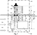
- Fig. 1 shows a cross-sectional view of an apparatus according to a preferred embodiment of this invention, which is used in a small-scale icing wind tunnel.
- the main goal of the presented apparatus is to introduce mono-dispensed super-cooled water droplets 106 into the air flow 116 of a wind tunnel and have them impact on a specimen located in the test section of the wind tunnel (not shown).
- the droplets 106 are produced and super-cooled by a liquid droplet production means 101 before introduction into the wind tunnel air flow 116 by the liquid droplet dispensing means 102.
- the liquid droplet dispensing means 102 is designed to introduce the droplets 106 into a settling chamber of the wind tunnel in manner that produces repeatable droplet impacts with a specimen in the test section of the wind tunnel.
- the liquid droplet production means 101 is arranged outside the wind tunnel settling chamber (in Fig. 1 the part above the wind tunnel wall 111), while the liquid droplet dispensing means 102 is arranged inside the wind tunnel settling chamber (in Fig. 1 the part below the wind tunnel wall 111), thus extending completely into the gas flow 116.
- Fig. 1 shows the arrangement of the apparatus at the upper wall 111 of the settling chamber of a small scale icing wind tunnel.
- the liquid droplet production means 101 comprise a droplet generator 103 to produce mono-dispersed liquid droplets 106 of given size having ambient temperature.
- the droplets 106 are introduced into a vertically arranged channel 105 which is connected to the outlet of the droplet generator 103 at the first end 150 of the channel 105.
- the channel 105 has a circular cross-section and is surrounded by a volume 110 of a cooling means 104, which in the present case is formed by an outer channel also having a circular cross-section.
- the volume 110 of the cooling means 104 has one inlet 108 and one outlet 109 and is otherwise a closed volume.
- a cooling medium is circulated as indicated by the arrows 107.
- the temperature of the cooling medium controls the temperature of the air inside the channel 105.
- the cooling of the liquid droplets 106 inside the channel 105 depends on the time the droplets 106 spends inside the channel 105 and the temperature of the air inside the channel 105.
- the liquid production means 101 is extending through the wind tunnel wall 111 until the inner surface of the settling chamber and is connected to the liquid droplet dispensing means 102.
- the channel 105 and the inner tube 160 are formed as one continuous inner tube, such that droplets 106 produced by the droplet generator 103 are introduced into this continuous inner tube at the upper end of the cooling channel 105 and leave this continuous inner tube at the second end of the inner tube 160.
- the outer channel and the outer tube 112 are formed as a continuous outer tube with their upper end being connected gas tightly to the droplet generator 103, and their lower end being open to the gas flow 116 inside the settling chamber of the wind tunnel.
- the liquid droplet dispensing means 102 comprise a vertically oriented straight outer tube 112 having a length l1, a first end 140 and a second end 141, the second end 141 comprising a tube outlet 119, a vertically oriented straight inner tube 160 having a length l2 with l2 ⁇ l1, a first end 130 and a second end 131, the first end 140 comprising a tube inlet, the second end 141 comprising a tube outlet, wherein the inner tube 160 being arranged inside the outer tube 112 with the outer surface of the inner tube 160 being disposed at distance from the inner surface of the outer tube 112, the first end 140 of the outer tube 112 and the first end 130 of the inner tube 160 being co-located, the outlet 151 of the liquid droplet producing means 101 being connected to the tube inlet of the inner tube 160 such that the liquid droplets 106 being dispensed from the said means 101 into the inner tube 160 substantially along a center axis of the inner tube 160, and the volume between the inner tube 160 and
- the embodiment shown in Fig. 1 comprises an outer tube 112 with two portions, a first portion extending from the first end 140 of the outer tube 112 in direction to the second end 141 until a cross section of the outer tube 112 located at a distance d2 from said first end 140, wherein the first portion encompassing the tube-wall-opening 113, and a second portion extending from said cross section to the second end 141 of the outer tube 112, the second portion comprising a body 115 having a cross section oriented perpendicular to the center axis of the body 115, said cross section a symmetric NACA-shaped profile.
- the tube wall opening 113 provides a pressure relief that supports the droplets 106 in leaving the inner tube 160. Additionally, the body 115 provides for reducing the wake turbulence downstream the outlet 141 of the outer tube 112. The flow induced inside the outer tube 112 by the tube-wall opening 113 proceeds uniformly from the tube wall opening 113 to the outlet 119 of the outer tube 112, thereby minimizing collisions of the droplets 106 with tube walls and maximizing the number of droplets 106 that exit the outer tube 112.
- the cross section of the airfoil body 115 reduces wake turbulence and enhances repeatability of droplet impact with the specimen in the test section of the wind tunnel.
- the resulting closed design is a fully encapsulated droplet delivery system that does not introduce warm air from the outside into the wind tunnel.
- the outer tube 112 is not restricted to a circular cross section and may have any shape that facilitates delivery of the droplets 106 so they impact the test specimen.
- the cylindrical outer tube 112 has a length l1 of 22.5 cm with 22 mm outer diameter.
- the thickness of the outer tube wall is 2 mm, so that the inner diameter of the outer tube 112 measures 18 mm.
- the tube-wall opening 113 is located on the downstream side of the outer tube 112 tube near the upper wall 111 of the settling chamber. This design allows air from the leeward side of the outer tube 112 to enter the tube-wall opening 113 and proceed towards the outlet 119 of the outer tube 112 at the second end 141.
- the tube-wall opening 113 is located 2.5 mm below the upper wall 111 of the wind tunnel settling chamber and measures 36.3 mm tall by 6.74 mm wide. This dimension of the tube-wall opening 113 is selected such that its area is equal to the cross-sectional area of the outer tube 112, especially the cross-sectional area of the outlet 119 of the outer tube 112.
- the concentrically mounted inside the outer tube 112 was introduced to produce a predominantly axial flow and reduce the undesirable effects associated with the unsteady flow in the pressure relief tunnel-wall opening 113.
- the outlet 118 of the inner tube 160 is located 36.2 mm lower than the bottom of the tube-wall opening (at distance d1b from the wind tunnel wall 111) to protect the droplets 106 from the inflow of the tube-wall opening 113, which might adversely affect the droplet trajectories.
- the inner cylindrically formed tube 160 has a length l2 of 7.5 cm and measures 8 mm in outer diameter.
- the walls of the inner tube 160 were assumed to have a thickness of 1 mm such that the inside diameter measures 6 mm.
- the outer diameter of the inner tube 160 is chosen to limit blockage inside the outer tube 112.
- a second feature of the outer tube 112 design is its cross-section profile in the vicinity of the second end 141 of the outer tube 112.
- the presented circular cylinder cross-section design is preferable due to similarity to the liquid droplet producing means 101, but it introduces significant unsteady artifacts to the downstream flow via a turbulent wake.
- hybrid geometry was introduced that combine a cylinder geometry at an upper part of the dispensing means 102 and an airfoil-shaped collar/body 115 at the lower part of the dispensing mean 102, respectively the lower part of the outer tube 112.
- the cylindrical cross-section allows an easy incorporation of the tube-wall opening 113 while the airfoil body 115 introduces a more streamlined geometry in critical regions of the wind tunnel air flow 116.
- the tube-wall opening 113 of the outer tube 112 would encourage a more uniform flow for the droplets 106.
- the tube-wall opening 113 and the inner tube 160 were removed from the design of the liquid droplet dispensing means 102 and compared with a design of the liquid droplet dispensing means 102 comprising the tube-wall opening 113 and the inner tube 160 to determine the effect of the tube-wall opening 113 on the flow inside the outer tube 112 and its subsequent effect on the droplet trajectories.
- Fig. 2 shows a cross-sectional view of the dispension means 102 and instantaneous droplet positions for an outer tube 112 without a tube-wall opening 113.
- the droplets 106 inside the inner tube 160 fall unaffected for some length until adverse vertical air flow in the outer tube 112 reduces the droplet velocities in downward direction, alter their trajectories, and increase the scattering of droplets 106 and their concentration in the outer tube 112.
- Fig. 3 shows a cross-sectional view of the dispension means 102 and instantaneous droplet positions for an outer tube 112 with a tube-wall opening 113 in the outer tube 112. Examination of this configuration shows that the downward directed velocity of the droplets 106 increases as they fall through the outer tube 112. A swirl of droplets 106 in the outer tube 112 is an evidence of residual effects of flow around the inner tube 160. The dispersion of droplets 106 created by the swirling flow does not affect the scatter of droplets 106 as much as the dispersion caused by the adverse flow. More droplets 106 exit the outlet 119 of the outer tube 112.
- Fig. 4 shows the scattering of droplets 106 that exit the outlet 119 of the outer tube 112 at intersections of droplet trajectories with an exit plane determined by the x- (401) and y-(402) axis and located at the second end 140 of the outer tube 112 over a time interval of 0.152 s for two configurations of the liquid droplet dispensing means 102.
- the plane is arranged perpendicular to a longitudinal axis of the outer tube 112.
- a first configuration is defined as having no inner tube 120 and no tube-wall opening 113, and a second is defined as having an inner tube 120 and a tube-wall opening 113.
- Intersections 404 for the first configuration are marked with 'x'.
- Intersections 405 for the second configuration are marked with '+'.
- Fig. 4 it is clear from Fig. 4 that in the second configuration there are significantly more droplets 106 that exit the outer tube 112 during the given time interval. In the second configuration the droplets that exit further show a more concentrated and centered distribution of impacts on the exit plane.
- the reference numeral 403 refers to the cross-section of the outlet 119 of outer tube 112. Further examination showed that in the second configuration fewer droplets 106 impact the wall of the outer tube 112 during the time interval.
- the dispensing means 102 configured with the second configuration increase the rate of droplets 106 successfully exiting the outer tube 112 during this time interval and decrease the scattering of droplet trajectories in the exit plane.
- the cylindrically cross section design of the outer tube 112 tend to scatter droplets 106 that have exit the outlet 119 and tend to deflect them upward due to fluctuating velocity components in the wake of the outer tube 112. Presumably less scatter and therefore more reliable droplet trajectories would be the result of employing a cross section in the lower part of the outer tube 112 that produces less turbulence in its wake. To test this hypothesis, three different NACA-airfoil bodies 115 have been tested in lieu of a circular cross-section of the outer tube 112.
- the three different airfoil-shaped collars were installed just below the tube-wall opening 113 on the outer tube 112, so that the favorable effects of the opening 113 and the inner tube 160 could be maintained.
- the three configurations were based on NACA0020, NACA0030, and NACA0040 airfoil profiles. The thickness of the profile was held constant and the chord of the profile decreased in order to keep the same tube diameter.
- the cylindrical cross-section of the outer tube 112 shows a strong, very active turbulent wake.
- Each of the outer tube configurations with an airfoil body 115 produces significantly smaller regions of high intensity turbulent flow than the cylindrical outer tube 112.
- the intensity of the turbulent fluctuations increases.
- the NACA0040 profile which has turbulence levels approaching those of the cylinder in regions of the wake, has reduced turbulence levels near the outlet 119 of the outer tube 112, which has more impact on the droplet trajectories.
- the NACA0020 cross section nearly eliminates all of the turbulence near the outlet 119 of the outer tube 112, and thus the NACA0020 profile is the preferred profile.
Claims (13)
- Vorrichtung, die sich zum Abgeben von monodispersen Flüssigkeitströpfchen (106) in einen Gasstrom (116) eignet, umfassend:- ein Flüssigkeitströpfchenerzeugungsmittel (101) zum Erzeugen monodisperser Flüssigkeitströpfchen (106), wobei das Mittel (101) eine Austrittsöffnung (151) für die monodispersen Flüssigkeitströpfchen (106) umfasst; und- Abgabemittel (102), umfassend:- eine äußere Röhre (112) mit einer Länge l1, einem ersten Ende (140) und einem zweiten Ende (141), wobei das zweite Ende (141) eine Röhrenaustrittsöffnung (119) umfasst;- eine innere Röhre (160) mit einer Länge l2, wobei l2 < 11, einem ersten Ende (130) und einem zweiten Ende (131), wobei das erste Ende (130) eine Röhreneintrittsöffnung umfasst, wobei das zweite Ende (131) eine Röhrenaustrittsöffnung (118) umfasst, wobei die innere Röhre (160) in der äußeren Röhre (112) angeordnet ist, wobei die Außenfläche der inneren Röhre (150) in einem Abstand zur Innenfläche der äußeren Röhre (112) angeordnet ist, wobei sich das erste Ende (140) der äußeren Röhre (112) und das erste Ende (130) der inneren Röhre (160) an derselben Stelle befinden, wobei die Austrittsöffnung (151) des Flüssigkeitströpfchenerzeugungsmittels (101) derart mit der Röhreneintrittsöffnung der inneren Röhre (160) verbunden ist, dass die Flüssigkeitströpfchen (106) aus dem Mittel (101) in die innere Röhre (160) im Wesentlichen entlang einer Mittelachse der inneren Röhre (160) abgegeben werden;dadurch gekennzeichnet, dass
eine Röhrenwandöffnung (113) auf einer in Strömungsrichtung davor befindlichen Seite der äußeren Röhre (112) angeordnet ist, wobei die Röhrenwandöffnung (113) entlang einer Mittelachse der äußeren Röhre (112) von einem von einem Abstand d1a zu einem Abstand d1b verläuft, wobei beide Abstände d1a, d1b bezogen auf die an derselben Stelle befindlichen ersten Enden (130, 140) der inneren Röhre (160) und der äußeren Röhre (112) gemessen sind und wobei: d1b < 12 und d1a < d1b, und wobei die innere Röhre (160) und äußere Röhre (112) konzentrisch entlang einer gemeinsamen senkrecht angeordneten mittigen Achse angeordnet sind. - Vorrichtung nach Anspruch 1, wobei das Flüssigkeitströpfchenerzeugungsmittel (101) so ausgelegt ist, dass es unterkühlte Flüssigkeitströpfchen (106) mit einer vorgegebenen Temperatur erzeugt und abgibt.
- Vorrichtung nach einem der Ansprüche 1 bis 2, wobei das Flüssigkeitströpfchenerzeugungsmittel (101) Folgendes umfasst:- einen Flüssigkeitströpfchenerzeuger (103) mit einer Austrittsöffnung für Flüssigkeitströpfchen (106);- einen Kanal (105) mit einer Länge 13, einem ersten Ende (150) und einem zweiten Ende (151), wobei das erste Ende (150) des Kanals (105) derart mit der Austrittsöffnung des Tröpfchenerzeugers verbunden ist, dass die Flüssigkeitströpfchen aus dem Erzeuger (103) in den Kanal (105) im Wesentlichen entlang einer Mittelachse des Kanals (105) abgegeben werden, und wobei das zweite Ende (151) des Kanals (105) die Austrittsöffnung des Flüssigkeitströpfchenerzeugungsmittels (101) ist; und- Kühlmittel (104) in Wärmekontakt mit dem Kanal (105) zum Kühlen des Kanals (105).
- Vorrichtung nach Anspruch 3, wobei die Kühlmittel (104) ein Volumen (110) umfassen, das mindestens einen Teil einer Außenfläche des Kanals (105) umgibt, wobei das Volumen (110) eine Eintrittsöffnung (108) und eine Austrittsöffnung (109) aufweist und das Volumen (110), die Eintrittsöffnung (108) und die Austrittsöffnung (109) für ein Kühlmittel durchlässig sind.
- Vorrichtung nach einem der Ansprüche 1 bis 4, wobei ein Profil eines Querschnitts der äußeren Röhre entlang der Mittelachse der äußeren Röhre konstant ist.
- Vorrichtung nach Anspruch 5, wobei der Querschnitt der äußeren Röhre (112) ein kreisförmiges Profil oder ein tropfenförmiges Profil oder ein symmetrisch geformtes Flügelprofil oder ein symmetrisch geformtes NACA-Profil aufweist.
- Vorrichtung nach einem der Ansprüche 1 bis 5, wobei die äußere Röhre (112) zwei Abschnitte umfasst:- einen ersten Abschnitt, der vom ersten Ende (140) der äußeren Röhre (112) in Richtung des zweiten Endes (141) bis zu einem Querschnitt der äußeren Röhre (112) verläuft, der sich in einem Abstand d2 vom ersten Ende (140) befindet, wobei der erste Abschnitt die Röhrenwandöffnung (113) umgibt, und- einen zweiten Abschnitt, der von dem Querschnitt zum zweiten Ende (141) der äußeren Röhre (112) verläuft; wobei der zweite Abschnitt einen Körper (115) mit einem Querschnitt senkrecht zu einer Mittelachse des äußeren Körpers (115) aufweist, wobei der Querschnitt ein tropfenförmiges Profil oder ein symmetrisches flügelförmiges Profil oder ein symmetrisches NACA-Formprofil ist.
- Vorrichtung nach Anspruch 7, wobei das NACA-Formprofil ein NACA0020- oder NACA0030- oder NACA0040-Profil ist.
- Vorrichtung nach einem der Ansprüche 1 bis 8, wobei 12 ausgewählt ist aus einem Bereich: [1,2 * d1b, 5 * d1b], [1,5 * d1b, 3,5 * d1b] oder [2* d1b, 2,5 * d1b].
- Vorrichtung nach einem der Ansprüche 1 bis 9, wobei 11 ausgewählt ist aus einem Bereich: [100 mm, 700 mm], [100 mm, 500 mm], [100 mm, 400 mm], [150 mm, 300 mm] oder [150 mm, 250 mm].
- Vorrichtung nach einem der Ansprüche 1 bis 10, wobei das Verhältnis 12 / 11 ausgewählt ist aus dem Bereich: [0,1, 0,7], [0,1, 0,5], [0,1, 0,3] oder [0,15, 2,25].
- Vorrichtung nach einem der Ansprüche 1 bis 11, wobei d1a ausgewählt ist aus einem Bereich: [0, 50 mm], [0, 25 mm], [0, 10 mm], [0, 5 mm], [1 mm, 3 mm], [2 mm, 2,5 mm].
- Windkanal mit einer Vorrichtung nach einem der Ansprüche 1 bis 12, wobei die Vorrichtung an einer oberen Windkanalwand in Strömungsrichtung vor einem Prüfabschnitt des Windkanals angeordnet ist, wobei die äußere Röhre (112) in den Luftstrom (116) hinein verläuft.
Priority Applications (1)
| Application Number | Priority Date | Filing Date | Title |
|---|---|---|---|
| PCT/EP2012/001880 WO2012152405A2 (en) | 2011-05-06 | 2012-05-02 | Apparatus for dispensing liquid droplets into a gas flow |
Applications Claiming Priority (1)
| Application Number | Priority Date | Filing Date | Title |
|---|---|---|---|
| US201161483379P | 2011-05-06 | 2011-05-06 |
Publications (3)
| Publication Number | Publication Date |
|---|---|
| EP2520509A2 EP2520509A2 (de) | 2012-11-07 |
| EP2520509A3 EP2520509A3 (de) | 2013-05-01 |
| EP2520509B1 true EP2520509B1 (de) | 2017-10-04 |
Family
ID=44542958
Family Applications (1)
| Application Number | Title | Priority Date | Filing Date |
|---|---|---|---|
| EP11006462.3A Active EP2520509B1 (de) | 2011-05-06 | 2011-08-05 | Vorrichtung zum Abgeben von Flüssigkeitstropfen in einen Gasstrom |
Country Status (2)
| Country | Link |
|---|---|
| EP (1) | EP2520509B1 (de) |
| WO (1) | WO2012152405A2 (de) |
Cited By (2)
| Publication number | Priority date | Publication date | Assignee | Title |
|---|---|---|---|---|
| CN110702419A (zh) * | 2019-10-11 | 2020-01-17 | 中国直升机设计研究所 | 一种发动机进气系统防冰符合性试验系统及方法 |
| CN111076888A (zh) * | 2020-01-10 | 2020-04-28 | 北京航空航天大学 | 一种用于积冰粘附力测量的小型垂直回流冰风洞实验装置 |
Families Citing this family (10)
| Publication number | Priority date | Publication date | Assignee | Title |
|---|---|---|---|---|
| US8650944B2 (en) * | 2012-03-13 | 2014-02-18 | The Boeing Company | Supercooled large drop icing condition simulation system |
| PE20160959A1 (es) * | 2015-10-14 | 2016-09-20 | Alvarez Adrian Eduardo Palomo | Medidor de la velocidad del aire por movimiento parabolico y procedimiento de medicion |
| CN106885686B (zh) * | 2017-03-20 | 2018-12-14 | 华中科技大学 | 一种液滴高速撞壁的试验装置 |
| CN111289206B (zh) * | 2020-04-28 | 2020-08-14 | 中国空气动力研究与发展中心低速空气动力研究所 | 一种冰形测量辅助装置及方法 |
| CN111307406B (zh) * | 2020-05-06 | 2020-11-06 | 中国空气动力研究与发展中心低速空气动力研究所 | 一种结冰风洞液态水含量测量方法 |
| CN111563354B (zh) * | 2020-06-10 | 2020-10-16 | 中国空气动力研究与发展中心低速空气动力研究所 | 一种基于数值模拟的结冰风洞试验相似转换方法 |
| CN112197932B (zh) * | 2020-12-07 | 2021-03-12 | 中国空气动力研究与发展中心低速空气动力研究所 | 一种飞机防除冰试验模型表面温度修正方法及测量方法 |
| CN112197933B (zh) * | 2020-12-10 | 2021-02-26 | 中国空气动力研究与发展中心低速空气动力研究所 | 可调宽度的开口射流风洞驻室及开口射流风洞试验方法 |
| CN113280570B (zh) * | 2021-07-13 | 2021-10-22 | 中国飞机强度研究所 | 一种过冷水滴生成装置 |
| CN114169256B (zh) * | 2022-02-14 | 2022-04-19 | 中国空气动力研究与发展中心低速空气动力研究所 | 一种获得结冰风洞缩比试验工况最优风速的方法 |
Citations (3)
| Publication number | Priority date | Publication date | Assignee | Title |
|---|---|---|---|---|
| US20010003148A1 (en) * | 1997-07-22 | 2001-06-07 | Coffee Ronald Alan | Dispensing device and method for forming material |
| US20060185511A1 (en) * | 2005-02-24 | 2006-08-24 | Tepper Gary C | Contaminant extraction systems, methods and apparatuses |
| US20080173327A1 (en) * | 2006-12-15 | 2008-07-24 | Masahiro Miyagi | Two-fluid nozzle, substrate processing apparatus, and substrate processing method |
Family Cites Families (12)
| Publication number | Priority date | Publication date | Assignee | Title |
|---|---|---|---|---|
| US3087332A (en) | 1961-06-27 | 1963-04-30 | Werner K Kern | Wind tunnel droplet dispenser |
| US3908903A (en) * | 1974-02-11 | 1975-09-30 | Jr Samuel L Burns | Snow making apparatus and method |
| JPH0469539A (ja) | 1990-07-09 | 1992-03-04 | Mitsubishi Heavy Ind Ltd | 液体微粒子発生装置 |
| JPH0470535A (ja) | 1990-07-12 | 1992-03-05 | Mitsubishi Heavy Ind Ltd | 航空機試験風洞 |
| US5324286A (en) * | 1993-01-21 | 1994-06-28 | Arthur A. Fowle, Inc. | Entrained cryogenic droplet transfer method and cryosurgical instrument |
| US5346133A (en) * | 1993-03-25 | 1994-09-13 | The M. W. Kellogg Company | High temperature liquid injection apparatus |
| US5931721A (en) * | 1994-11-07 | 1999-08-03 | Sumitomo Heavy Industries, Ltd. | Aerosol surface processing |
| JP2000035261A (ja) * | 1998-07-15 | 2000-02-02 | Paloma Ind Ltd | 吸収式冷凍機 |
| US6444009B1 (en) * | 2001-04-12 | 2002-09-03 | Nanotek Instruments, Inc. | Method for producing environmentally stable reactive alloy powders |
| US7777868B2 (en) * | 2006-11-07 | 2010-08-17 | Fluid Measurement Technologies, Inc. | System for measuring non-volatile residue in ultra pure water |
| EP3964821A1 (de) * | 2008-09-23 | 2022-03-09 | Bio-Rad Laboratories, Inc. | Tröpfchenbasiertes testsystem |
| FI125490B (fi) * | 2009-06-18 | 2015-10-30 | Beneq Oy | Menetelmä ja laitteisto materiaalin karkaisemiseksi |
-
2011
- 2011-08-05 EP EP11006462.3A patent/EP2520509B1/de active Active
-
2012
- 2012-05-02 WO PCT/EP2012/001880 patent/WO2012152405A2/en active Application Filing
Patent Citations (3)
| Publication number | Priority date | Publication date | Assignee | Title |
|---|---|---|---|---|
| US20010003148A1 (en) * | 1997-07-22 | 2001-06-07 | Coffee Ronald Alan | Dispensing device and method for forming material |
| US20060185511A1 (en) * | 2005-02-24 | 2006-08-24 | Tepper Gary C | Contaminant extraction systems, methods and apparatuses |
| US20080173327A1 (en) * | 2006-12-15 | 2008-07-24 | Masahiro Miyagi | Two-fluid nozzle, substrate processing apparatus, and substrate processing method |
Cited By (3)
| Publication number | Priority date | Publication date | Assignee | Title |
|---|---|---|---|---|
| CN110702419A (zh) * | 2019-10-11 | 2020-01-17 | 中国直升机设计研究所 | 一种发动机进气系统防冰符合性试验系统及方法 |
| CN110702419B (zh) * | 2019-10-11 | 2021-08-06 | 中国直升机设计研究所 | 一种发动机进气系统防冰符合性试验系统及方法 |
| CN111076888A (zh) * | 2020-01-10 | 2020-04-28 | 北京航空航天大学 | 一种用于积冰粘附力测量的小型垂直回流冰风洞实验装置 |
Also Published As
| Publication number | Publication date |
|---|---|
| WO2012152405A3 (en) | 2013-05-10 |
| EP2520509A3 (de) | 2013-05-01 |
| EP2520509A2 (de) | 2012-11-07 |
| WO2012152405A2 (en) | 2012-11-15 |
Similar Documents
| Publication | Publication Date | Title |
|---|---|---|
| EP2520509B1 (de) | Vorrichtung zum Abgeben von Flüssigkeitstropfen in einen Gasstrom | |
| Ahmed et al. | An investigation on the aerodynamics of a symmetrical airfoil in ground effect | |
| Villermaux et al. | Drop fragmentation on impact | |
| US20090035579A1 (en) | Solid particles, method and device for the production thereof | |
| WO2003106260A1 (en) | Controlling boundary layer fluid flow | |
| Wu | Drop “impact” on an airfoil surface | |
| Baumert et al. | Simulating natural ice crystal cloud conditions for icing wind tunnel experiments-A review on the design, commissioning and calibration of the TU Braunschweig ice crystal generation system | |
| Yu et al. | The influence of elliptical and circular orifices on the transverse jet characteristics at supersonic crossflow | |
| Akhmetov et al. | Flow structure in a Ranque− Hilsch vortex tube | |
| Chauhan et al. | Aspect ratio effect on elliptical sonic jet mixing | |
| CN103056044B (zh) | 超声速自由旋涡纳米粒子分离装置 | |
| McClintic et al. | Near-hole thermal field measurements for round compound angle film cooling holes fed by cross-flow | |
| US4281540A (en) | Low turbulence wind tunnel stilling chamber | |
| RU2638376C1 (ru) | Стенд для исследования деформации капель аэродинамическими силами | |
| Roos et al. | Synthetic-jet microblowing for vortex asymmetry management on a hemisphere-cylinder forebody | |
| Leu et al. | Experimental investigation of side force control on cone-cylinder slender bodies with flexible micro balloon actuators | |
| JP2012083251A (ja) | エロージョン予測評価方法 | |
| Ma et al. | Effects of forced asymmetric transition on vortex asymmetry around slender bodies | |
| Bartoš et al. | An experimental study of the coarse droplets formation | |
| Dghim et al. | Stereoscopic PIV Investigation of the Effect of Synthetic Jet Actuation on a Wingtip Vortex | |
| Aley et al. | Experimental characterization of a high-lift supercritical airfoil with microjets | |
| Fernandez et al. | Active separation control on highly loaded lpt blades using microjets | |
| Wan et al. | Numerical simulations of parachute aerodynamic characteristics under severe weather | |
| Davison et al. | Naturally Aspirating Isokinetic Total Water Content Probe: Preliminary Test Results and Design Modifications | |
| Zerrout et al. | Experimental and numerical investigation of the thermal and dynamic behavior of a heated vortex multijet system impacting a flat plate |
Legal Events
| Date | Code | Title | Description |
|---|---|---|---|
| PUAI | Public reference made under article 153(3) epc to a published international application that has entered the european phase |
Free format text: ORIGINAL CODE: 0009012 |
|
| AK | Designated contracting states |
Kind code of ref document: A2 Designated state(s): AL AT BE BG CH CY CZ DE DK EE ES FI FR GB GR HR HU IE IS IT LI LT LU LV MC MK MT NL NO PL PT RO RS SE SI SK SM TR |
|
| AX | Request for extension of the european patent |
Extension state: BA ME |
|
| PUAL | Search report despatched |
Free format text: ORIGINAL CODE: 0009013 |
|
| AK | Designated contracting states |
Kind code of ref document: A3 Designated state(s): AL AT BE BG CH CY CZ DE DK EE ES FI FR GB GR HR HU IE IS IT LI LT LU LV MC MK MT NL NO PL PT RO RS SE SI SK SM TR |
|
| AX | Request for extension of the european patent |
Extension state: BA ME |
|
| RIC1 | Information provided on ipc code assigned before grant |
Ipc: B65D 47/18 20060101AFI20130322BHEP |
|
| RIN1 | Information on inventor provided before grant (corrected) |
Inventor name: DR. RAPS, DOMINIK Inventor name: DR. THOMPSON, DAVID Inventor name: JUNG, STEFAN Inventor name: HUTCHINGS, KYLE |
|
| RIN1 | Information on inventor provided before grant (corrected) |
Inventor name: DR. THOMPSON, DAVID Inventor name: DR. RAPS, DOMINIK Inventor name: JUNG, STEFAN Inventor name: HUTCHINGS, KYLE |
|
| 17P | Request for examination filed |
Effective date: 20131008 |
|
| RBV | Designated contracting states (corrected) |
Designated state(s): AL AT BE BG CH CY CZ DE DK EE ES FI FR GB GR HR HU IE IS IT LI LT LU LV MC MK MT NL NO PL PT RO RS SE SI SK SM TR |
|
| RAP1 | Party data changed (applicant data changed or rights of an application transferred) |
Owner name: AIRBUS DEFENCE AND SPACE GMBH |
|
| RIN1 | Information on inventor provided before grant (corrected) |
Inventor name: DR. RAPS, DOMINIK Inventor name: JUNG, STEFAN Inventor name: DR. THOMPSON, DAVID Inventor name: HUTCHINGS, KYLE |
|
| 17Q | First examination report despatched |
Effective date: 20150706 |
|
| REG | Reference to a national code |
Ref country code: DE Ref legal event code: R079 Ref document number: 602011042045 Country of ref document: DE Free format text: PREVIOUS MAIN CLASS: B65D0047180000 Ipc: G01M0009060000 |
|
| GRAP | Despatch of communication of intention to grant a patent |
Free format text: ORIGINAL CODE: EPIDOSNIGR1 |
|
| STAA | Information on the status of an ep patent application or granted ep patent |
Free format text: STATUS: GRANT OF PATENT IS INTENDED |
|
| RIC1 | Information provided on ipc code assigned before grant |
Ipc: G01M 9/06 20060101AFI20170201BHEP |
|
| INTG | Intention to grant announced |
Effective date: 20170228 |
|
| GRAS | Grant fee paid |
Free format text: ORIGINAL CODE: EPIDOSNIGR3 |
|
| GRAA | (expected) grant |
Free format text: ORIGINAL CODE: 0009210 |
|
| STAA | Information on the status of an ep patent application or granted ep patent |
Free format text: STATUS: THE PATENT HAS BEEN GRANTED |
|
| RIN1 | Information on inventor provided before grant (corrected) |
Inventor name: JUNG, STEFAN Inventor name: HUTCHINGS, KYLE Inventor name: RAPS, DOMINIK, DR. Inventor name: THOMPSON, DAVID, DR. |
|
| AK | Designated contracting states |
Kind code of ref document: B1 Designated state(s): AL AT BE BG CH CY CZ DE DK EE ES FI FR GB GR HR HU IE IS IT LI LT LU LV MC MK MT NL NO PL PT RO RS SE SI SK SM TR |
|
| REG | Reference to a national code |
Ref country code: GB Ref legal event code: FG4D |
|
| REG | Reference to a national code |
Ref country code: CH Ref legal event code: EP |
|
| REG | Reference to a national code |
Ref country code: AT Ref legal event code: REF Ref document number: 934487 Country of ref document: AT Kind code of ref document: T Effective date: 20171015 |
|
| REG | Reference to a national code |
Ref country code: IE Ref legal event code: FG4D |
|
| REG | Reference to a national code |
Ref country code: DE Ref legal event code: R096 Ref document number: 602011042045 Country of ref document: DE |
|
| REG | Reference to a national code |
Ref country code: NL Ref legal event code: MP Effective date: 20171004 |
|
| REG | Reference to a national code |
Ref country code: LT Ref legal event code: MG4D |
|
| REG | Reference to a national code |
Ref country code: AT Ref legal event code: MK05 Ref document number: 934487 Country of ref document: AT Kind code of ref document: T Effective date: 20171004 |
|
| PG25 | Lapsed in a contracting state [announced via postgrant information from national office to epo] |
Ref country code: NL Free format text: LAPSE BECAUSE OF FAILURE TO SUBMIT A TRANSLATION OF THE DESCRIPTION OR TO PAY THE FEE WITHIN THE PRESCRIBED TIME-LIMIT Effective date: 20171004 |
|
| PG25 | Lapsed in a contracting state [announced via postgrant information from national office to epo] |
Ref country code: NO Free format text: LAPSE BECAUSE OF FAILURE TO SUBMIT A TRANSLATION OF THE DESCRIPTION OR TO PAY THE FEE WITHIN THE PRESCRIBED TIME-LIMIT Effective date: 20180104 Ref country code: LT Free format text: LAPSE BECAUSE OF FAILURE TO SUBMIT A TRANSLATION OF THE DESCRIPTION OR TO PAY THE FEE WITHIN THE PRESCRIBED TIME-LIMIT Effective date: 20171004 Ref country code: SE Free format text: LAPSE BECAUSE OF FAILURE TO SUBMIT A TRANSLATION OF THE DESCRIPTION OR TO PAY THE FEE WITHIN THE PRESCRIBED TIME-LIMIT Effective date: 20171004 Ref country code: FI Free format text: LAPSE BECAUSE OF FAILURE TO SUBMIT A TRANSLATION OF THE DESCRIPTION OR TO PAY THE FEE WITHIN THE PRESCRIBED TIME-LIMIT Effective date: 20171004 Ref country code: ES Free format text: LAPSE BECAUSE OF FAILURE TO SUBMIT A TRANSLATION OF THE DESCRIPTION OR TO PAY THE FEE WITHIN THE PRESCRIBED TIME-LIMIT Effective date: 20171004 |
|
| PG25 | Lapsed in a contracting state [announced via postgrant information from national office to epo] |
Ref country code: HR Free format text: LAPSE BECAUSE OF FAILURE TO SUBMIT A TRANSLATION OF THE DESCRIPTION OR TO PAY THE FEE WITHIN THE PRESCRIBED TIME-LIMIT Effective date: 20171004 Ref country code: GR Free format text: LAPSE BECAUSE OF FAILURE TO SUBMIT A TRANSLATION OF THE DESCRIPTION OR TO PAY THE FEE WITHIN THE PRESCRIBED TIME-LIMIT Effective date: 20180105 Ref country code: LV Free format text: LAPSE BECAUSE OF FAILURE TO SUBMIT A TRANSLATION OF THE DESCRIPTION OR TO PAY THE FEE WITHIN THE PRESCRIBED TIME-LIMIT Effective date: 20171004 Ref country code: IS Free format text: LAPSE BECAUSE OF FAILURE TO SUBMIT A TRANSLATION OF THE DESCRIPTION OR TO PAY THE FEE WITHIN THE PRESCRIBED TIME-LIMIT Effective date: 20180204 Ref country code: RS Free format text: LAPSE BECAUSE OF FAILURE TO SUBMIT A TRANSLATION OF THE DESCRIPTION OR TO PAY THE FEE WITHIN THE PRESCRIBED TIME-LIMIT Effective date: 20171004 Ref country code: BG Free format text: LAPSE BECAUSE OF FAILURE TO SUBMIT A TRANSLATION OF THE DESCRIPTION OR TO PAY THE FEE WITHIN THE PRESCRIBED TIME-LIMIT Effective date: 20180104 Ref country code: AT Free format text: LAPSE BECAUSE OF FAILURE TO SUBMIT A TRANSLATION OF THE DESCRIPTION OR TO PAY THE FEE WITHIN THE PRESCRIBED TIME-LIMIT Effective date: 20171004 |
|
| REG | Reference to a national code |
Ref country code: DE Ref legal event code: R097 Ref document number: 602011042045 Country of ref document: DE |
|
| PG25 | Lapsed in a contracting state [announced via postgrant information from national office to epo] |
Ref country code: DK Free format text: LAPSE BECAUSE OF FAILURE TO SUBMIT A TRANSLATION OF THE DESCRIPTION OR TO PAY THE FEE WITHIN THE PRESCRIBED TIME-LIMIT Effective date: 20171004 Ref country code: SK Free format text: LAPSE BECAUSE OF FAILURE TO SUBMIT A TRANSLATION OF THE DESCRIPTION OR TO PAY THE FEE WITHIN THE PRESCRIBED TIME-LIMIT Effective date: 20171004 Ref country code: CZ Free format text: LAPSE BECAUSE OF FAILURE TO SUBMIT A TRANSLATION OF THE DESCRIPTION OR TO PAY THE FEE WITHIN THE PRESCRIBED TIME-LIMIT Effective date: 20171004 Ref country code: EE Free format text: LAPSE BECAUSE OF FAILURE TO SUBMIT A TRANSLATION OF THE DESCRIPTION OR TO PAY THE FEE WITHIN THE PRESCRIBED TIME-LIMIT Effective date: 20171004 |
|
| PLBE | No opposition filed within time limit |
Free format text: ORIGINAL CODE: 0009261 |
|
| STAA | Information on the status of an ep patent application or granted ep patent |
Free format text: STATUS: NO OPPOSITION FILED WITHIN TIME LIMIT |
|
| REG | Reference to a national code |
Ref country code: FR Ref legal event code: PLFP Year of fee payment: 8 |
|
| PG25 | Lapsed in a contracting state [announced via postgrant information from national office to epo] |
Ref country code: PL Free format text: LAPSE BECAUSE OF FAILURE TO SUBMIT A TRANSLATION OF THE DESCRIPTION OR TO PAY THE FEE WITHIN THE PRESCRIBED TIME-LIMIT Effective date: 20171004 Ref country code: RO Free format text: LAPSE BECAUSE OF FAILURE TO SUBMIT A TRANSLATION OF THE DESCRIPTION OR TO PAY THE FEE WITHIN THE PRESCRIBED TIME-LIMIT Effective date: 20171004 Ref country code: IT Free format text: LAPSE BECAUSE OF FAILURE TO SUBMIT A TRANSLATION OF THE DESCRIPTION OR TO PAY THE FEE WITHIN THE PRESCRIBED TIME-LIMIT Effective date: 20171004 Ref country code: SM Free format text: LAPSE BECAUSE OF FAILURE TO SUBMIT A TRANSLATION OF THE DESCRIPTION OR TO PAY THE FEE WITHIN THE PRESCRIBED TIME-LIMIT Effective date: 20171004 |
|
| 26N | No opposition filed |
Effective date: 20180705 |
|
| PG25 | Lapsed in a contracting state [announced via postgrant information from national office to epo] |
Ref country code: SI Free format text: LAPSE BECAUSE OF FAILURE TO SUBMIT A TRANSLATION OF THE DESCRIPTION OR TO PAY THE FEE WITHIN THE PRESCRIBED TIME-LIMIT Effective date: 20171004 |
|
| PG25 | Lapsed in a contracting state [announced via postgrant information from national office to epo] |
Ref country code: MC Free format text: LAPSE BECAUSE OF FAILURE TO SUBMIT A TRANSLATION OF THE DESCRIPTION OR TO PAY THE FEE WITHIN THE PRESCRIBED TIME-LIMIT Effective date: 20171004 |
|
| REG | Reference to a national code |
Ref country code: CH Ref legal event code: PL |
|
| GBPC | Gb: european patent ceased through non-payment of renewal fee |
Effective date: 20180805 |
|
| PG25 | Lapsed in a contracting state [announced via postgrant information from national office to epo] |
Ref country code: LU Free format text: LAPSE BECAUSE OF NON-PAYMENT OF DUE FEES Effective date: 20180805 Ref country code: LI Free format text: LAPSE BECAUSE OF NON-PAYMENT OF DUE FEES Effective date: 20180831 Ref country code: CH Free format text: LAPSE BECAUSE OF NON-PAYMENT OF DUE FEES Effective date: 20180831 |
|
| REG | Reference to a national code |
Ref country code: BE Ref legal event code: MM Effective date: 20180831 |
|
| REG | Reference to a national code |
Ref country code: IE Ref legal event code: MM4A |
|
| PG25 | Lapsed in a contracting state [announced via postgrant information from national office to epo] |
Ref country code: IE Free format text: LAPSE BECAUSE OF NON-PAYMENT OF DUE FEES Effective date: 20180805 |
|
| PG25 | Lapsed in a contracting state [announced via postgrant information from national office to epo] |
Ref country code: BE Free format text: LAPSE BECAUSE OF NON-PAYMENT OF DUE FEES Effective date: 20180831 |
|
| PG25 | Lapsed in a contracting state [announced via postgrant information from national office to epo] |
Ref country code: GB Free format text: LAPSE BECAUSE OF NON-PAYMENT OF DUE FEES Effective date: 20180805 |
|
| PG25 | Lapsed in a contracting state [announced via postgrant information from national office to epo] |
Ref country code: MT Free format text: LAPSE BECAUSE OF NON-PAYMENT OF DUE FEES Effective date: 20180805 |
|
| PG25 | Lapsed in a contracting state [announced via postgrant information from national office to epo] |
Ref country code: TR Free format text: LAPSE BECAUSE OF FAILURE TO SUBMIT A TRANSLATION OF THE DESCRIPTION OR TO PAY THE FEE WITHIN THE PRESCRIBED TIME-LIMIT Effective date: 20171004 |
|
| PG25 | Lapsed in a contracting state [announced via postgrant information from national office to epo] |
Ref country code: PT Free format text: LAPSE BECAUSE OF FAILURE TO SUBMIT A TRANSLATION OF THE DESCRIPTION OR TO PAY THE FEE WITHIN THE PRESCRIBED TIME-LIMIT Effective date: 20171004 Ref country code: HU Free format text: LAPSE BECAUSE OF FAILURE TO SUBMIT A TRANSLATION OF THE DESCRIPTION OR TO PAY THE FEE WITHIN THE PRESCRIBED TIME-LIMIT; INVALID AB INITIO Effective date: 20110805 |
|
| PG25 | Lapsed in a contracting state [announced via postgrant information from national office to epo] |
Ref country code: CY Free format text: LAPSE BECAUSE OF FAILURE TO SUBMIT A TRANSLATION OF THE DESCRIPTION OR TO PAY THE FEE WITHIN THE PRESCRIBED TIME-LIMIT Effective date: 20171004 Ref country code: MK Free format text: LAPSE BECAUSE OF NON-PAYMENT OF DUE FEES Effective date: 20171004 |
|
| PG25 | Lapsed in a contracting state [announced via postgrant information from national office to epo] |
Ref country code: AL Free format text: LAPSE BECAUSE OF FAILURE TO SUBMIT A TRANSLATION OF THE DESCRIPTION OR TO PAY THE FEE WITHIN THE PRESCRIBED TIME-LIMIT Effective date: 20171004 |
|
| PGFP | Annual fee paid to national office [announced via postgrant information from national office to epo] |
Ref country code: FR Payment date: 20230824 Year of fee payment: 13 Ref country code: DE Payment date: 20230821 Year of fee payment: 13 |