EP2518754A2 - Electric lamp with an external piston and a fitted lamp and production method - Google Patents
Electric lamp with an external piston and a fitted lamp and production method Download PDFInfo
- Publication number
- EP2518754A2 EP2518754A2 EP12164505A EP12164505A EP2518754A2 EP 2518754 A2 EP2518754 A2 EP 2518754A2 EP 12164505 A EP12164505 A EP 12164505A EP 12164505 A EP12164505 A EP 12164505A EP 2518754 A2 EP2518754 A2 EP 2518754A2
- Authority
- EP
- European Patent Office
- Prior art keywords
- lamp
- base
- power supply
- base body
- clip
- Prior art date
- Legal status (The legal status is an assumption and is not a legal conclusion. Google has not performed a legal analysis and makes no representation as to the accuracy of the status listed.)
- Withdrawn
Links
Images


Classifications
-
- H—ELECTRICITY
- H01—ELECTRIC ELEMENTS
- H01J—ELECTRIC DISCHARGE TUBES OR DISCHARGE LAMPS
- H01J5/00—Details relating to vessels or to leading-in conductors common to two or more basic types of discharge tubes or lamps
- H01J5/50—Means forming part of the tube or lamps for the purpose of providing electrical connection to it
- H01J5/54—Means forming part of the tube or lamps for the purpose of providing electrical connection to it supported by a separate part, e.g. base
- H01J5/58—Means for fastening the separate part to the vessel, e.g. by cement
- H01J5/60—Means for fastening the separate part to the vessel, e.g. by cement for fastening by mechanical means
-
- H—ELECTRICITY
- H01—ELECTRIC ELEMENTS
- H01J—ELECTRIC DISCHARGE TUBES OR DISCHARGE LAMPS
- H01J5/00—Details relating to vessels or to leading-in conductors common to two or more basic types of discharge tubes or lamps
- H01J5/50—Means forming part of the tube or lamps for the purpose of providing electrical connection to it
- H01J5/54—Means forming part of the tube or lamps for the purpose of providing electrical connection to it supported by a separate part, e.g. base
- H01J5/62—Connection of wires protruding from the vessel to connectors carried by the separate part
-
- H—ELECTRICITY
- H01—ELECTRIC ELEMENTS
- H01K—ELECTRIC INCANDESCENT LAMPS
- H01K1/00—Details
- H01K1/42—Means forming part of the lamp for the purpose of providing electrical connection, or support for, the lamp
- H01K1/46—Means forming part of the lamp for the purpose of providing electrical connection, or support for, the lamp supported by a separate part, e.g. base, cap
- H01K1/48—Removable caps
Definitions
- the object of the present invention is, in a lamp according to the preamble of claim 1, the installation of a built-in lamp in an outer bulb by means of mounting clip safely and reliably, but nevertheless to accomplish in a simple manner.
- the invention ensures the simple and reliable production of a lamp with built-in lamp.
- the invention provides, in particular, a single-ended electric lamp with an outer bulb fastened to a base and an integral lamp which is arranged inside the outer bulb and which is robust and easy to produce.
- the lamp or integral lamp is a high-voltage halogen incandescent lamp, wherein at least two pins act as power supply wires.
- the lamp can also be a high-pressure discharge lamp.
- the built-in lamp has a piston with pinch, which is held by means of a retaining clip on the plate base.
- the lamp or integral lamp consists essentially of a hermetically sealed lamp vessel or bulb with pinch, of at least one light source and a power supply system for the lamp, which usually has two external power supply lines, which protrude axially parallel from the pinch.
- the light source is usually a luminous element, but it can also be a discharge arc between two electrodes. In the following, the light source will always be described as a luminous element for the sake of simplicity. He is often over internal power supply and possibly films connected to the external power supply lines.
- the power supply system connects the lamp arranged in the interior of the lamp vessel with a lamp arranged outside the base, which is to be connected to a power source.
- the power supply system consists, for example, of inner power supply wires, of fuser films and of outer power supply wires, wherein the aligned ends of the inner and outer power supply wires and the power supply wires interconnecting fusing films are fused in the lamp crimp.
- Relevant to the invention is only the pinch and the outwardly projecting wires of the external power supply lines.
- the piston is usually filled with an inert gas and a halogen additive.
- a high-pressure discharge lamp can be used in particular as a built-in lamp, similar to DE-A 32 32 207 described.
- the joke of the invention is that the power supply is connected to a holding clip, which takes over the further contact with the socket for this power supply.
- the novel concept is particularly suitable for increasing the luminous flux of the lamp.
- the problem is solved to increase the efficiency of such lamps in the simplest possible way.
- the retaining clip consists of two independent clip parts, which can be similar in principle, albeit mirrored. Below is the construction a Garclipteils, often called only clip part described in more detail.
- the clip part has a pair of spring tongues for fixing the pinch of the built-in lamp and a docking station for the supply line, which protrudes from a Tellerfuß up to the recessed lamp out, as well as at least one body, which ensures the connection between the supply line and associated external power supply of the recessed lamp and at the same time either encloses the pinch laterally or serves as a stop for the foundation of the pinch. From this foundation, the external power supply of the built-in lamp exit.
- the base body and docking station are at a different height level with respect to the longitudinal axis, whereby, together with the spring tongues, a considerable material saving is achieved EP2239762 is achieved.
- body and docking station are at the same height level, which is why about twice as much material is required for the retaining clip part.
- the retaining clip can now be better adapted to the pinch of the recessed lamp.
- the centering part has in its inner surface an opening which serves as a centering inlet for an external power supply of the built-in lamp. This opening can be completely within the edge of the centering, but it can also extend as a recess partially to the edge. All parts are advantageously flat surfaces which are connected to each other via bends.
- auxiliary plate is attached, which is arranged at approximately 90 ° laterally to this first side wall. It is preferably oriented parallel to the base wall.
- a U-shaped clamping part attached as a docking station with two side walls which are oriented so that they are parallel to the free end of a protruding from the base plate of the lamp supply line supplied from the base forth is, are aligned.
- the distance between the two side walls to each other is just chosen so that the supply line or its free end can be clamped therein, which possibly happens by subsequent adjustment of this distance, whereby a good clamping effect is ensured. Since this distance is relatively small, the base part is rather poor compared to the side walls. Often it is just a bent connector. To save material and for easier bending, the clamping part often has recessed windows in the area of the base part.
- the two spring tongues are mutually substantially parallel and axially parallel to the longitudinal axis of the lamp. They are clamped to the two broad sides of the bruise.
- the free ends of the spring tongues are preferably corrugated.
- the socket takes place by serving as a holder for the integral lamp two retaining clip parts, which include the pinch of the integral lamp.
- the retaining clip parts are docked to the leads, which protrude from the disc base, as stated above. Then they are fixed by laser welding. Thereafter, a usual socket is attached.
- a secure connection is preferably achieved by laser welding between the feed line and the clamping part, similar to what happens between outer power supply and extension part of the base wall of the clip part, in particular, even both welding operations occur simultaneously or immediately in succession.
- the efficiency of the lamp is increased by minimizing the luminous flux losses in the direction of the base.
- the frame structure is changed and adapted the manufacturing process of the socket.
- the reflector disc also preferably has a first recess, which is preferably rectangular, for the disc base.
- each external power supply of the integral lamp is bent laterally to the nearest narrow side of the pinch and returned to this, preferably slightly protruding.
- the integral lamp is mounted on the clip, or on two clip parts, and attached the free end of the bent outer power supply to the clip part by laser or Widerstresch resumeen, in principle, also satisfies the mechanical contact.
- a reflector plate is attached to the bottom of the clip part, so that the pins of the clip part engage in the slots of the reflector disc, the free ends of the pins are angled adjoin, so that a locking of the reflector disc is ensured.
- the minimized shadowing of the clip keeps the luminous flux loss of the built-in lamp as low as possible.
- the luminous flux losses are reduced by the use of the reflector part.
- the bent-free end of the outer power supply engages other latching springs of the clip part, so that can be dispensed with extra welding.
- the auxiliary plate may have a transverse to the longitudinal axis attached support member for the reflector disk.
- the reflector disc has substantially as an edge on a circular arc and a straight edge which connects the ends of the circular arc.
- the reflector disc is not a separate part, but is attached integrally to the retaining clip.
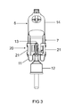
- FIG. 1 represents a complete halogen incandescent lamp 1.
- a base 2 of the commercial type E14 or E27 in particular with ceramic base or lamp support and attached screw 3 and base sleeve 4, an outer bulb 5 is held in the base sleeve 4 by means of putty.
- a built-in lamp 6 is arranged within the outer bulb 5.
- the integral lamp is designed as a so-called high-voltage halogen incandescent lamp and known as such from the prior art.
- the lamp 1 has a longitudinal axis A, on which the built-in lamp is aligned.
- the built-in lamp 6, see also FIG. 2 is equipped with a single pinch 7 having two broad sides 8a and 8b and two narrow sides 9a and 9b and a bottom part 10 equipped. From the pinch 7 project pin-like external power supply 11 out. According to FIG. 2 These outer power supply lines 11 are angled outwards in the direction of the narrow side of the pinch, the free ends are slightly obliquely outward. Slightly inclined means in particular at an angle of 5 to 30 ° inclined to the longitudinal axis A.
- a partial clip 21 connects an external power supply 11 via a main body and a docking station with a coming from the base forth supply line 13, which is melted in a cup base 12.
- FIGS. 4a and 4b shows in each case a section through the pinch seal 7 with retaining clip 20 and a detail of the docking station 33.
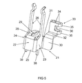
- FIG. 5 shows a partial clip 21 with a plate-like base body 22, which is divided into three U-shaped sub-plates.
- a first sub-plate is a side wall 23. It is parallel to the axis A and approximately in extension of second broad side 8b of the pinch 7 aligned and is located directly below the pinch 7.
- the first side wall 23 has an upper edge which shows a pinch, a lower edge which faces the socket, an inner edge which faces away from the axis A, and an outer edge which faces the axis A.
- two spring tongues 26 are arranged so that they face each other and thereby comprise the two broad sides 8a and 8b of the pinch.
- a centering 28 plate-like between the base of the two spring tongues 26 extends, however, angled at 90 °, a centering 28 plate-like between the base of the two spring tongues 26. It is essentially a rectangular plate having a substantially oval opening 29 in the middle, and the it is intended to center the free bent end of the outer power supply 11 and to contact, see above all FIG. 6a ,
- auxiliary plate 30 which branches off from the outer edge 31 of the side wall.
- extension part 32 is angled, which is oriented transversely to the longitudinal axis A, similar as well as the centering 28.
- the docking station 33 sits for coming from the base 2 ago supply line.
- the latch spring 46 presses with its free leg 49 against the outer power supply 11, whereby the mechanical contact is significantly improved.
- a laser welding for the connection is not essential here, but quite advantageous.
- An assembly process using the retaining clip is carried out in the following steps: First, the first and second clip part and the built-in lamp are provided with angled outer power supply lines.
- the base body is electrically connected to the base sleeve via a first supply line, thus the side contact is realized.
- the center contact is realized by soldering the extension wire in the ground contact of the socket, the eye.
Abstract
Description
Die Erfindung geht aus von einer Lampe gemäß dem Oberbegriff des Anspruchs 1. Die Erfindung betrifft insbesondere eine einseitig gesockelte elektrische Lampe mit einem in einem Sockel gehalterten Außenkolben und mindestens einer innerhalb des Außenkolbens angeordneten Einbaulampe. Derartige Halogenglühlampen sind insbesondere für Betrieb an Hochvolt (HV) mit typisch 100 bis 250 V gedacht.The invention relates to a lamp according to the preamble of
Die
Üblicherweise werden dabei zur Arretierung die von der Einbaulampe herausgeführten äußeren Stromzuführungen mit den aus dem Tellerfuß aufragenden Zuleitungen fest verbunden. Dafür ist eine aufwendige Maschinentechnik erforderlich.Usually, the outgoing from the built-in lamp outer power supply lines are firmly connected to the towering from the base plate feeder lines for locking. This requires a complex machine technology.
Die Aufgabe der vorliegenden Erfindung ist es, bei einer Lampe gemäß dem Oberbegriff des Anspruchs 1 die Montage einer Einbaulampe in einem Außenkolben mittels Montageclip sicher und zuverlässig, aber trotzdem auf einfache Weise zu bewerkstelligen.The object of the present invention is, in a lamp according to the preamble of
Diese Aufgabe wird gelöst durch die kennzeichnenden Merkmale des Anspruchs 1.This object is achieved by the characterizing features of
Besonders vorteilhafte Ausgestaltungen finden sich in den abhängigen Ansprüchen.Particularly advantageous embodiments can be found in the dependent claims.
In Abkehr von einem hoch automatisierten Prozess wird jetzt ein neuartiges Montagekonzept vorgeschlagen, das ohne aufwendige Justierung auskommt.In contrast to a highly automated process, a novel assembly concept is now proposed, which does not require any elaborate adjustment.
Der Erfindung sichert die einfache und zuverlässige Herstellung einer Lampe mit Einbaulampe. Die Erfindung schafft insbesondere eine einseitig gesockelte elektrische Lampe mit einem an einem Sockel befestigten Außenkolben und einer innerhalb des Außenkolbens angeordneten Einbaulampe, die robust und einfach herstellbar ist. Vorzugsweise ist die Lampe oder Einbaulampe eine Hochvolt-Halogenglühlampe, wobei mindestens zwei Stifte als Stromzuführungsdrähte wirken. Die Lampe kann aber auch eine Hochdruckentladungslampe sein. Die Einbaulampe weist einen Kolben mit Quetschung auf, der mittels eines Halteclips am Tellerfuß gehaltert ist.The invention ensures the simple and reliable production of a lamp with built-in lamp. The invention provides, in particular, a single-ended electric lamp with an outer bulb fastened to a base and an integral lamp which is arranged inside the outer bulb and which is robust and easy to produce. Preferably, the lamp or integral lamp is a high-voltage halogen incandescent lamp, wherein at least two pins act as power supply wires. The lamp can also be a high-pressure discharge lamp. The built-in lamp has a piston with pinch, which is held by means of a retaining clip on the plate base.
Die Lampe oder Einbaulampe besteht im wesentlichen aus einem hermetisch abgeschlossenen Lampengefäß oder Kolben mit Quetschung, aus wenigstens einem Leuchtmittel und einem Stromzuführungssystem für das Leuchtmittel, das in der Regel auch zwei äußere Stromzuführungen aufweist, die aus der Quetschung achsparallel herausragen. Das Leuchtmittel ist normalerweise ein Leuchtkörper, es kann aber auch ein Entladungsbogen zwischen zwei Elektroden sein. Im folgenden wird das Leuchtmittel der Einfachheit halber immer als Leuchtkörper beschrieben. Er ist häufig über innere Stromzuführungen und ggf. Folien mit den äußeren Stromzuführungen verbunden.The lamp or integral lamp consists essentially of a hermetically sealed lamp vessel or bulb with pinch, of at least one light source and a power supply system for the lamp, which usually has two external power supply lines, which protrude axially parallel from the pinch. The light source is usually a luminous element, but it can also be a discharge arc between two electrodes. In the following, the light source will always be described as a luminous element for the sake of simplicity. He is often over internal power supply and possibly films connected to the external power supply lines.
Das Stromzuführungssystem verbindet den im Inneren des Lampengefäßes angeordneten Leuchtkörper mit einem außerhalb des Lampengefäßes angeordneten Sockel, der mit einer Stromquelle zu verbinden ist. Das Stromzuführungssystem besteht beispielsweise aus inneren Stromzuführungsdrähten, aus Einschmelzfolien und aus äußeren Stromzuführungsdrähten, wobei die zueinander ausgerichteten Enden der inneren und äußeren Stromzuführungsdrähte und die die Stromzuführungsdrähte miteinander verbindenden Einschmelzfolien in der Lampenquetschung eingeschmolzen sind. Relevant für die Erfindung ist nur die Quetschung und die davon nach außen ragenden Drähte der äußeren Stromzuführungen. Der Kolben ist in der Regel mit einem Inertgas und einem Halogenzusatz gefüllt. Statt einer Glühlampe kann auch eine Hochdruckentladungslampe insbesondere als Einbaulampe verwendet werden, ähnlich wie in
Der Witz der Erfindung liegt darin, dass die Stromzuführung mit einem Halteclip verbunden wird, der für diese Stromzuführung die weitere Kontaktierung zum Sockel hin übernimmt.The joke of the invention is that the power supply is connected to a holding clip, which takes over the further contact with the socket for this power supply.
Das neuartige Konzept eignet sich insbesondere dazu, den Lichtstrom der Lampe zu erhöhen. Somit wird die Aufgabe gelöst, die Effizienz derartiger Lampen auf möglichst einfache Weise zu erhöhen.The novel concept is particularly suitable for increasing the luminous flux of the lamp. Thus, the problem is solved to increase the efficiency of such lamps in the simplest possible way.
Der Halteclip besteht aus zwei voneinander unabhängigen Clipteilen, die im Prinzip gleichartig, wenn auch spiegelverkehrt, sein können. Nachfolgend wird die Konstruktion eines Halteclipteils, oft nur Clipteil genannt, näher beschrieben.The retaining clip consists of two independent clip parts, which can be similar in principle, albeit mirrored. Below is the construction a Halteclipteils, often called only clip part described in more detail.
Das Clipteil weist ein Paar Federzungen zur Fixierung der Quetschung der Einbaulampe auf sowie eine Andockstation für die Zuleitung, die aus einem Tellerfuß nach oben zur Einbaulampe hin ragt, sowie zumindest noch einen Grundkörper, der die Verbindung zwischen Zuleitung und zugehöriger äußerer Stromzuführung der Einbaulampe sicherstellt und gleichzeitig entweder die Quetschung seitlich umschließt oder als Anschlag für das Fundament der Quetschung dient. Aus diesem Fundament treten die äußeren Stromzuführungen der Einbaulampe aus.The clip part has a pair of spring tongues for fixing the pinch of the built-in lamp and a docking station for the supply line, which protrudes from a Tellerfuß up to the recessed lamp out, as well as at least one body, which ensures the connection between the supply line and associated external power supply of the recessed lamp and at the same time either encloses the pinch laterally or serves as a stop for the foundation of the pinch. From this foundation, the external power supply of the built-in lamp exit.
In einer bevorzugten Ausführungsform ist der Grundkörper U-förmig gebogen, mit zwei Seitenwänden und einer Basiswand. Insbesondere sind die beiden Federzungen jeweils an einer der Seitenwände des Grundkörpers angesetzt.In a preferred embodiment, the base body is bent in a U-shape, with two side walls and a base wall. In particular, the two spring tongues are each attached to one of the side walls of the body.
Vorteilhaft liegen Grundkörper und Andockstation auf einem unterschiedlichen Höhenniveau in Bezug auf die Längsachse, wodurch zusammen mit den Federzungen eine ganz erhebliche Materialeinsparung gegenüber
Vorteilhaft ist außerdem ein Reflektorteil mit dem Clipteil verbunden, wobei das Reflektorteil bevorzugt im wesentlichen quer zur Längsachse der Einbaulampe angeordnet ist. Bevorzugt ist das Reflektorteil ein Ausschnitt einer Scheibe, im wesentlichen kann es insbesondere als Kreissegment verstanden werden. Das Reflektorteil kann mechanisch mit dem Clipteil verbunden sein oder integral daran angeformt sein.In addition, a reflector part is advantageously connected to the clip part, wherein the reflector part is preferably arranged substantially transversely to the longitudinal axis of the built-in lamp. Preferably, the reflector part is a section of a disc, it can in particular be a circle segment in particular be understood. The reflector part may be mechanically connected to the clip part or integrally formed thereon.
Die Quetschung der Einbaulampe wird bevorzugt mittels zweier einander gegenüberliegender Federzungen im Bereich eines seitlichen Randes der Quetschung gehaltert. Entsprechend können gleichartige Federzungen eines zweiten Halteclipteils auch den gegenüberliegenden zweiten seitlichen Rand der Quetschung haltern.The pinch of the integral lamp is preferably held by means of two mutually opposite spring tongues in the region of a lateral edge of the pinch. Accordingly, similar spring tongues of a second retaining clip part can also support the opposite second lateral edge of the pinch seal.
Die Federzungen enden an Seitenwänden eines U-förmigen Basisteils, das weiterhin noch eine Basiswand aufweist. Die drei Wände sind etwa rechtwinkelig zueinander, die Grundfläche von Seitenwand und Basiswand sind etwa gleich groß -bevorzugt unterscheiden sie sich um höchsten 30% der Fläche voneinander - und sind achsparallel zur Längsachse der Einbaulampe orientiert.The spring tongues end on side walls of a U-shaped base part, which still has a base wall. The three walls are approximately at right angles to each other, the base area of side wall and base wall are approximately the same size - preferably they differ by the highest 30% of the surface from each other - and are oriented axially parallel to the longitudinal axis of the built-in lamp.
Von der Basiswand erstreckt sich vorteilhaft ein etwa rechtwinkelig abgebogenes Zentrierteil in den Raum zwischen die beiden Federzungen. Das Zentrierteil weist in seiner Innenfläche eine Öffnung auf, die als Zentriereinlauf für eine äußere Stromzuführung der Einbaulampe dient. Diese Öffnung kann vollständig innerhalb des Randes des Zentrierteils liegen, sie kann sich aber auch als Aussparung teilweise bis zum Rand erstrecken. Alle Teile sind vorteilhaft ebene Flächen, die über Biegungen miteinander verbunden sind.From the base wall advantageously extends approximately at right angles bent centering in the space between the two spring tongues. The centering part has in its inner surface an opening which serves as a centering inlet for an external power supply of the built-in lamp. This opening can be completely within the edge of the centering, but it can also extend as a recess partially to the edge. All parts are advantageously flat surfaces which are connected to each other via bends.
An den Seitenwänden sitzen den Federzungen gegenüberliegend zwei Zapfen als Option, deren Sinn weiter unten erläutert wird. Wenn man die Federzungen als an der oberen Kante der Seitenwand anschließend betrachtet, sitzen diese Zapfen also an der unteren Kante, bevorzugt in Verlängerung der Federzunge.On the side walls of the spring tongues opposite two pins sit as an option, the meaning will be explained below. If you then consider the spring tongues as at the upper edge of the sidewall, they sit Pin so at the lower edge, preferably in extension of the spring tongue.
An der freien Endkante einer ersten Seitenwand ist außerdem eine etwa rechteckige Hilfsplatte angesetzt, die um etwa 90° seitlich zu dieser ersten Seitenwand angeordnet ist. Sie ist bevorzugt parallel zur Basiswand orientiert.At the free end edge of a first side wall also an approximately rectangular auxiliary plate is attached, which is arranged at approximately 90 ° laterally to this first side wall. It is preferably oriented parallel to the base wall.
An die Hilfsplatte ist, ggf. über ein plattenartiges Umlenkteil, ein U-förmiges Klemmteil als Andockstation angesetzt, mit zwei Seitenwänden, die so orientiert sind, dass sie parallel zum freien Ende einer aus dem Tellerfuß der Lampe ragenden Zuleitung, die vom Sockel her zugeführt ist, ausgerichtet sind. Der Abstand der beiden Seitenwände zueinander ist gerade so gewählt, dass die Zuleitung bzw. deren freies Ende darin eingeklemmt werden kann, was ggf. durch nachträgliche Anpassung dieses Abstands geschieht, wodurch ein gute Klemmwirkung sichergestellt wird. Da dieser Abstand relativ klein ist, ist das Basisteil eher kümmerlich ausgebildet, verglichen mit den Seitenwänden. Oft ist es nur ein gebogenes Verbindungsstück. Zur Materialeinsparung und zum leichteren Biegen weist das Klemmteil im Bereich des Basisteils oft ausgesparte Fenster auf.To the auxiliary plate, possibly via a plate-like deflection part, a U-shaped clamping part attached as a docking station, with two side walls which are oriented so that they are parallel to the free end of a protruding from the base plate of the lamp supply line supplied from the base forth is, are aligned. The distance between the two side walls to each other is just chosen so that the supply line or its free end can be clamped therein, which possibly happens by subsequent adjustment of this distance, whereby a good clamping effect is ensured. Since this distance is relatively small, the base part is rather poor compared to the side walls. Often it is just a bent connector. To save material and for easier bending, the clamping part often has recessed windows in the area of the base part.
Die beiden Federzungen sind zueinander im wesentlichen parallel und achsparallel zur Längsachse der Lampe. Sie liegen klemmend an den beiden Breitseiten der Quetschung an .The two spring tongues are mutually substantially parallel and axially parallel to the longitudinal axis of the lamp. They are clamped to the two broad sides of the bruise.
Zur sicheren Fixierung der Quetschung ohne Spiel sind die freien Enden der Federzungen bevorzugt gewellt.For secure fixation of the pinch without play the free ends of the spring tongues are preferably corrugated.
Mit einem derartigen Halteclip konnte der Ausschuss bei der Montage der Einbaulampe im Sockel auf etwa ein Drittel des vorher üblichen Wertes gesenkt werden.With such a retaining clip, the rejects could be reduced to about one third of the usual value when mounting the built-in lamp in the base.
Bei der einfachsten Ausführungsform des Halteclips erfolgt die Sockelung, indem als Halterung für die Einbaulampe zwei Halteclipteile dienen, die die Quetschung der Einbaulampe umfassen. Dabei werden die Halteclipteile an den Zuleitungen, die aus dem Tellerfuß ragen, angedockt, wie oben dargelegt. Anschließend werden sie durch Laserschweißen fixiert. Danach wird ein üblicher Sockel angesetzt.In the simplest embodiment of the retaining clip, the socket takes place by serving as a holder for the integral lamp two retaining clip parts, which include the pinch of the integral lamp. In this case, the retaining clip parts are docked to the leads, which protrude from the disc base, as stated above. Then they are fixed by laser welding. Thereafter, a usual socket is attached.
Bei der Montage des Clipteils werden außerdem die aus dem Tellerfuß ragenden Zuleitungen zwischen die Seitenwände des Klemmteils bzw. der Andockstation eingepasst. Ggf. wird der Abstand der Seitenwände des Klemmteils danach verringert.During assembly of the clip part, the supply lines protruding from the plate foot are also fitted between the side walls of the clamping part or the docking station. Possibly. the distance of the side walls of the clamping part is then reduced.
Eine sichere Verbindung wird bevorzugt durch Laserschweißen zwischen der Zuleitung und dem Klemmteil erzielt, ähnlich wie dies auch zwischen äußerer Stromzuführung und Verlängerungsteils der Basiswand des Clipteils geschieht, insbesondere erfolgen sogar beide Schweißvorgänge gleichzeitig oder unmittelbar aufeinanderfolgend.A secure connection is preferably achieved by laser welding between the feed line and the clamping part, similar to what happens between outer power supply and extension part of the base wall of the clip part, in particular, even both welding operations occur simultaneously or immediately in succession.
In einer besonders bevorzugten Ausführungsform wird die Effizienz der Lampe dadurch erhöht, dass die Lichtstromverluste in Richtung Sockel minimiert werden. Dafür wird der Gestellaufbau verändert und das Herstellverfahren der Sockelung angepasst.In a particularly preferred embodiment, the efficiency of the lamp is increased by minimizing the luminous flux losses in the direction of the base. For this, the frame structure is changed and adapted the manufacturing process of the socket.
Dies geschieht, indem eine Reflektorscheibe, die im Prinzip als Halbkreis oder Kreissegment ausgeführt ist, auf den Clip aufgesteckt wird, diese Reflektorscheibe wird gefügt, wobei die Scheibe zwei Schlitze aufweist, in die die oben erwähnten Zapfen des Clipteils eingeführt werden.This is done by a reflector disc, which is designed in principle as a semicircle or circular segment on the clip is fitted, this reflector disc is joined, wherein the disc has two slots, in which the above-mentioned pins of the clip part are inserted.
Die Reflektorscheibe hat außerdem bevorzugt eine erste Aussparung, die bevorzugt rechteckig ist, für den Tellerfuß.The reflector disc also preferably has a first recess, which is preferably rectangular, for the disc base.
Zwischen den beiden Schlitzen hat sie außerdem bevorzugt eine zweite Aussparung für die äußere Stromzuführung der Einbaulampe. Diese zweite Aussparung kann insbesondere so angeordnet sein, dass sie direkt an die erste Aussparung anschließt. Beide Aussparungen können rechteckig sein, insbesondere sind die Längsachsen der beiden Aussparungen quer zueinander angeordnet.Between the two slots, it also preferably has a second recess for the external power supply of the recessed lamp. This second recess can in particular be arranged so that it directly adjoins the first recess. Both recesses may be rectangular, in particular, the longitudinal axes of the two recesses are arranged transversely to each other.
Vor der Sockelung wird jede äußere Stromzuführung der Einbaulampe seitlich zur nächstliegenden Schmalseite der Quetschung umgebogen und an dieser, bevorzugt leicht abstehend, wieder zurückgeführt.Before the socket, each external power supply of the integral lamp is bent laterally to the nearest narrow side of the pinch and returned to this, preferably slightly protruding.
Die Einbaulampe wird auf den Clip, bzw. auf zwei Clipteile, gefügt und das freie Ende der umgebogenen äußeren Stromzuführung am Clipteil durch Laser oder auch Widerstrandschweißen befestigt, im Prinzip genügt auch der mechanische Kontakt.The integral lamp is mounted on the clip, or on two clip parts, and attached the free end of the bent outer power supply to the clip part by laser or Widerstreschweißen, in principle, also satisfies the mechanical contact.
Anschließend wird eine Reflektorscheibe unten an das Clipteil angesetzt, so dass die Zapfen des Clipteils in die Schlitze der Reflektorscheibe einrasten, die freien enden der Zapfen werden anschließen abgewinkelt, so dass eine Arretierung der Reflektorscheibe sichergestellt ist.Subsequently, a reflector plate is attached to the bottom of the clip part, so that the pins of the clip part engage in the slots of the reflector disc, the free ends of the pins are angled adjoin, so that a locking of the reflector disc is ensured.
Vorteile des Hinzufügens der Reflektorschieben sind, dass durch die minimierte Abschattung des Clips der Lichtstromverlust der Einbaulampe so gering wie möglich gehalten wird. Außerdem werden durch die Verwendung des Reflektorteils die Lichtstromverluste verringert.Advantages of adding the reflector slides are that the minimized shadowing of the clip keeps the luminous flux loss of the built-in lamp as low as possible. In addition, the luminous flux losses are reduced by the use of the reflector part.
Durch das optimal gestaltete Clipteil mit minimaler Abschattung an der Quetschung der Einbaulampe und die Anwendung der Reflektorscheiben werden die Lichtstromverluste verringert. Die Montage erfolgt, indem die Reflektorschieben, die bevorzugt aus Metall, hier insbesondere Aluminium verspiegelt oder hochglanzbeschichtet bzw. plattiert bzw. chromiert, gefertigt sind, am Clipteil montiert werden. Dies geschieht durch Umbiegen der Zapfen bzw. durch Aufpressen. Zwei Clipteile werden gleichzeitig oder zeitnah hintereinander auf die Einbaulampe gefügt, die gebogenen äußeren Stromzuführungen der Einbaulampe zentrieren sich im Zentriereinlauf des Clipteils von selbst. Die äußere Stromzuführung der Einbaulampe mit dem Clipteil erfolgt bevorzugt mittels Laserschweißen. Die Baueinheit Einbaulampe/Clipteile wird auf die beiden Zuleitungen, die aus dem Tellerfuß ragen, gefügt, anschließend wird auch hier mittels Laserschweißen o.ä. die Verbindung gesichert.The optimally designed clip part with minimal shading at the pinch of the recessed lamp and the application of the reflector discs reduce the luminous flux losses. The assembly is carried out by the reflector slides, which are preferably made of metal, in particular aluminum mirrored or high gloss coated or plated or chromed, are mounted on the clip part. This is done by bending the pins or by pressing. Two clip parts are added simultaneously or in rapid succession to the built-in lamp, the curved outer power supply of the recessed lamp center themselves in the centering of the clip part. The external power supply of the recessed lamp with the clip part is preferably carried out by laser welding. The assembly unit lamp / clip parts is on the two leads, which protrude from the plate base, joined, then also by laser welding o.ä. secured the connection.
In einer anderen Ausführungsform rastet das umgebogene frei Ende der äußeren Stromzuführung an weiteren Einrastfedern des Clipteils ein, so dass auf eine extra Schweißung verzichtet werden kann.In another embodiment, the bent-free end of the outer power supply engages other latching springs of the clip part, so that can be dispensed with extra welding.
Bevorzugt kann die Hilfsplatte ein quer zur Längsachse angesetztes Stützelement für die Reflektorscheibe aufweisen.Preferably, the auxiliary plate may have a transverse to the longitudinal axis attached support member for the reflector disk.
Die Reflektorscheibe weist im wesentlichen als Rand einen Kreisbogen und eine gerade Kante auf, die die Enden des Kreisbogens verbindet.The reflector disc has substantially as an edge on a circular arc and a straight edge which connects the ends of the circular arc.
Vorteilhaft ist die Reflektorscheibe an einem oder auch beiden Enden der geraden Kante mit einer davon wegstehenden Flosse ausgestattet, wobei die Flosse insbesondere nach oben abgewinkelt sein kann. Dadurch wird die rückstrahlende Fläche, die von beiden Reflektorschieben zusammen aufgespannt wird, deutlich vergrößert werden. Wenn beide Reflektorscheiben eine derartige Flosse spiegelverkehrt zueinander besitzen, ist eine weitgehende Rückreflexion von in Richtung des Sockels emittierter Strahlung sichergestellt. Die Biegung der Flosse sichert dabei die Möglichkeit des Überlapps zur benachbarten Reflektorscheibe ohne dass aus Toleranzgründen ein Abstand gewahrt werden müsste.Advantageously, the reflector disk is provided at one or both ends of the straight edge with a fin projecting therefrom, wherein the fin can be angled upwards in particular. As a result, the retroreflective surface, which is spanned together by two reflector slides, be significantly increased. If both reflector discs have such a fin mirrored to each other, a substantial back reflection of radiation emitted in the direction of the base radiation is ensured. The bending of the fin secures the possibility of overlap to the adjacent reflector disc without tolerance reasons, a distance would have to be maintained.
In einer weiteren Ausführungsform ist die Reflektorscheibe kein separates Teil, sondern integral an den Halteclip angesetzt.In a further embodiment, the reflector disc is not a separate part, but is attached integrally to the retaining clip.
Bevorzugtes Material für den Halteclip ist Federstahl oder Blech.Preferred material for the retaining clip is spring steel or sheet metal.
Wesentliche Merkmale der Erfindung in Form einer numerierten Aufzählung sind:
- 1. Elektrische Lampe mit einem Außenkolben und mit einem daran mittels eines Tellerfußes befestigten Sockel sowie mit einer Einbaulampe mit Längsachse, wobei der Außenkolben die Einbaulampe umschließt, die mit einer Quetschung mit zwei Schmalseiten und zwei Breitseiten ausgestattet ist, wobei aus der Quetschung zwei äußere Stromzuführungen herausragen, die ihrerseits mit zum Sockel führenden Zuleitungen elektrisch leitend verbunden sind, wobei die Einbaulampe kittlos durch einen Halteclip gehaltert ist, dadurch gekennzeichnet, dass der Halteclip zumindest ein Clipteil aufweist, das einen U-förmig gebogenen Grundkörper besitzt, wobei am Grundkörper zwei Federzungen so angeordnet sind, dass sie die Breitseiten der Quetschung umklammern, wobei am Grundkörper außerdem eine Andockstation für eine Zuleitung angesetzt ist und wobei der Grundkörper eine äußere Stromzuführung kontaktiert.
- 2.
Lampe nach Anspruch 1, dadurch gekennzeichnet, dass Grundkörper und Andockstation bezogen auf die Längsachse in unterschiedlichen Höhen sitzen. - 3.
Lampe nach Anspruch 1, dadurch gekennzeichnet, dass der Grundkörper eine Basiswand und zwei Seitenwände besitzt, wobei ein Zentriereinlauf für die äußere Stromzuführung von der Basiswand abgewinkelt ist. - 4.
Lampe nach Anspruch 1, dadurch gekennzeichnet, dass Grundkörper und Andockstation über eine Hilfsplatte, die gegen den Grundkörper abgewinkelt ist, verbunden sind. - 5.
Lampe nach Anspruch 1, dadurch gekennzeichnet, dass dem Clipteil ein reflektierender Scheibenausschnitt zugeordnet ist, der sich quer zur Längsachse erstreckt. - 6.
Lampe nach Anspruch 5, dadurch gekennzeichnet, dass der Grundkörper zapfenartige Auswüchse aufweist, wobei der Scheibenausschnitt entsprechende Aussparungen zur Arretierung des Scheibenausschnitts besitzt. - 7.
Lampe nach Anspruch 5, dadurch gekennzeichnet, dass der Scheibenausschnitt integral am Grundkörper angesetzt ist, insbesondere an einer Seitenwand des Grundkörpers. - 8.
Lampe nach Anspruch 1, dadurch gekennzeichnet, dass die äußere Stromzuführung seitlich zur Schmalseite der Quetschung hin abgewinkelt ist. - 9.
Lampe nach Anspruch 5, dadurch gekennzeichnet, dass der Scheibenausschnitt zusätzlich eine Flosse aufweist, die die Fläche für die Reflexion vergrößert. - 10.
Lampe nach Anspruch 1, dadurch gekennzeichnet, dass dem Grundkörper eine steigbügelartig geformte Einrastfeder zur Kontaktierung der abgebogenen äußeren Stromzuführung angesetzt ist, insbesondere mit einem starren Schenkel, der am Grundkörper befestigt ist, einem Brückenteil und einem freien Schenkel, der seitlich gegen die äußere Stromzuführung drückt. - 11.Verfahren zur Herstellung einer elektrischen Lampe gemäß
Anspruch 1, dadurch gekennzeichnet, dass in einem ersten Schritt ein Verlängerungsdraht mit einer zweiten äußeren Stromzuführung der Einbaulampe verbunden wird, danach die Einbaulampe mit dem Halteclip mechanisch verbunden wird, insbesondere zwischen mindestens zwei Federzungen der Schürze gefügt wird, danach die erste äußere Stromzuführung direkt mit der Schürze verbunden wird, insbesondere mittels eines an der Schürze ausgebildeten Wulstes, danach Kitt in die Sockelhülse eingebracht wird, danach die Baueinheit aus Einbaulampe und Halteclip in die Sockelhülse unter Kontaktnahme der Federfüße mit der Sockelhülse gefügt wird, danach der Außenkolben auf die Sockelhülse gefügt wird, danach der Kitt ausgeheizt wird und schließlich der Bodenkontakt mit dem Verlängerungsdraht verbunden wird. - 12.Verfahren zur Herstellung einer elektrischen Lampe gemäß Anspruch 9
oder 10, dadurch gekennzeichnet, dass in einem ersten Schritt ein Verlängerungsdraht mit einer zweiten äußeren Stromzuführung der Einbaulampe verbunden wird, danach die Einbaulampe durch das Reflektorteil hindurchgefädelt wird und mit dem Halteclip mechanisch verbunden wird, insbesondere zwischen mindestens zwei Federzungen der Schürze gefügt wird, danach die erste äußere Stromzuführung direkt mit der Schürze verbunden wird, insbesondere mittels eines an der Schürze ausgebildeten Wulstes, danach Kitt in die Sockelhülse eingebracht wird, danach die Baueinheit aus Einbaulampe und Halteclip in die Sockelhülse unter Kontaktnahme der Federfüße mit der Sockelhülse gefügt wird, danach der Außenkolben auf die Sockelhülse gefügt wird, danach der Kitt ausgeheizt wird und schließlich der Bodenkontakt mit dem Verlängerungsdraht verbunden wird.
- 1. Electric lamp with an outer bulb and a base attached thereto by means of a base plate and with a built-in lamp with longitudinal axis, wherein the outer bulb encloses the built-in lamp, which is equipped with a pinch with two narrow sides and two broad sides, said from Pinch two external power supply lines protrude, which in turn are electrically connected to leading to the socket leads, the integral lamp is supported kittlos by a retaining clip, characterized in that the retaining clip has at least one clip part having a U-shaped base body, said on Base body two spring tongues are arranged so that they clasp the broad sides of the pinch, wherein on the base body also a docking station is attached for a supply line and wherein the main body contacts an external power supply.
- 2. Lamp according to
claim 1, characterized in that the base body and docking seat relative to the longitudinal axis sit at different heights. - 3. Lamp according to
claim 1, characterized in that the base body has a base wall and two side walls, wherein a centering inlet for the external power supply is angled from the base wall. - 4. Lamp according to
claim 1, characterized in that the base body and docking station via an auxiliary plate, which is angled against the base body, are connected. - 5. Lamp according to
claim 1, characterized in that the clip part is associated with a reflective disk cutout which extends transversely to the longitudinal axis. - 6. Lamp according to
claim 5, characterized in that the main body has pin-like outgrowths, wherein the disk cutout has corresponding recesses for locking the disk cutout. - 7. Lamp according to
claim 5, characterized in that the disk cutout is attached integrally to the base body, in particular on a side wall of the base body. - 8. Lamp according to
claim 1, characterized in that the outer power supply is angled laterally to the narrow side of the pinch. - 9. Lamp according to
claim 5, characterized in that the disk cutout additionally has a fin, which increases the area for reflection. - 10.Lampe according to
claim 1, characterized in that the base body is a stirrup-like shaped latching spring for contacting the bent outer power supply is attached, in particular with a rigid leg which is fixed to the base body, a bridge portion and a free leg, the laterally against the outer Power supply presses. - 11.Verfahren for producing an electric lamp according to
claim 1, characterized in that in a first step, an extension wire is connected to a second external power supply of the built-in lamp, then the integral lamp is mechanically connected to the retaining clip, in particular between at least two spring tongues of the skirt joined is, then the first external power supply is connected directly to the skirt, in particular by means of a bead formed on the skirt, then putty is introduced into the base sleeve, then the assembly of built-in lamp and retaining clip is joined in the base sleeve by contacting the spring feet with the base sleeve, then the outer bulb on the base sleeve is then heated, then the putty is baked and finally the ground contact is connected to the extension wire. - 12.Verfahren for producing an electric lamp according to
claim 9 or 10, characterized in that in a first step, an extension wire is connected to a second external power supply of the recessed lamp, then the recessed lamp is threaded through the reflector member and is mechanically connected to the retaining clip, in particular between at least two spring tongues of the skirt is joined, then the first external power supply is connected directly to the apron, in particular by means of a skirt formed on the skirt, then putty is introduced into the base sleeve, then the assembly of built-in lamp and retaining clip in the base sleeve below Contact the spring feet is joined to the base sleeve, then the outer bulb is joined to the base sleeve, then the putty is baked out and finally the ground contact is connected to the extension wire.
Im Folgenden soll die Erfindung anhand mehrerer Ausführungsbeispiele näher erläutert werden. Die Figuren zeigen:
Figur 1- eine Prinzipdarstellung einer erfindungsgemäßen Lampe;
Figur 2- eine Einbaulampe im Detail;
Figur 3- ein Detail der Einbaulampe mit Halteclip;
Figur 4- eine Ansicht des Andockbereichs von oben (
Figur 4a ) und im Detail (Figur 4b ); Figur 5- eine Ansicht eines Clipteils perspektivisch;
Figur 6- eine Ansicht der Einbaulampe mit Halteclip in zwei Perspektiven (
Figur 6a und6b ); Figur 7- ein weiteres Ausführungsbeispiel eines Teilclips mit Reflektorscheibe;
- Figur 8
- eine Ansicht einer Einbaulampe mit Halteclip gemäß
Teilclip von Figur 7 in zwei Perspektiven (Figur 8a8b ); - Figur 9
- ein weiteres Ausführungsbeispiel eines Teilclips in zwei Perspektiven (
Figur 9a9b ); Figur 10- ein Detail einer Einbaulampe mit Halteclip gemäß Teilclip von
Figur 9 ; Figur 11- ein weiteres Ausführungsbeispiel eines Teilclips;
Figur 12- eine Seitenansicht eines Details einer Einbaulampe mit Halteclip gemäß
Teilclip von Figur 11 ; Figur 13- eine perspektivische Ansicht eines Details einer Einbaulampe mit Halteclip gemäß
Teilclip von Figur 11 ; Figur 14- ein weiteres Ausführungsbeispiel eines Teilclips.
- FIG. 1
- a schematic diagram of a lamp according to the invention;
- FIG. 2
- a built-in lamp in detail;
- FIG. 3
- a detail of the built-in lamp with retaining clip;
- FIG. 4
- a view of the docking area from above (
FIG. 4a ) and in detail (FIG. 4b ); - FIG. 5
- a view of a clip part in perspective;
- FIG. 6
- a view of the built-in lamp with retaining clip in two perspectives (
FIG. 6a and6b ); - FIG. 7
- a further embodiment of a partial clip with reflector disc;
- FIG. 8
- a view of a built-in lamp with retaining clip according to part clip of
FIG. 7 in two perspectives (FIG. 8a and8b ); - FIG. 9
- Another embodiment of a subclip in two perspectives (
FIG. 9a and9b ); - FIG. 10
- a detail of a built-in lamp with retaining clip according to part clip of
FIG. 9 ; - FIG. 11
- a further embodiment of a partial clip;
- FIG. 12
- a side view of a detail of a built-in lamp with retaining clip according to part clip of
FIG. 11 ; - FIG. 13
- a perspective view of a detail of a built-in lamp with retaining clip according to part clip of
FIG. 11 ; - FIG. 14
- another embodiment of a partial clip.
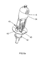
Die Einbaulampe 6, siehe auch
Die Einbaulampe 6 ist beispielsweise eine einseitig gequetschte Halogenglühlampe mit Lampengefäß 14, in dem ein Leuchtkörper 15 fixiert ist. Der Leuchtkörper 15 ist über ein Stromzuführungssystem mit dem Sockel 2 elektrisch leitend verbunden. Das Stromzuführungssystem besteht aus mit dem Leuchtkörper 15 verbundenen inneren Stromzuführungsdrähten 16, Einschmelzfolien 17 und äußeren Stromzuführungsdrähten 11. Die von dem Leuchtkörper 15 abgewandten Enden der inneren Stromzuführungsdrähte 16, die Einschmelzfolien 17 und die den Einschmelzfolien zugewandten Enden der äußeren Stromzuführungsdrähte 11 sind in der Quetschung 7, die das Lampengefäß 14 abschließt, eingeschmolzen.The built-in
Das Lampengefäß 14 ist mit einem Inertgas und Halogenzusatz gefüllt. An seinem der Quetschung 7 gegenüberliegenden Ende ist das Lampengefäß 14 abgeschmolzen (18). Das Lampengefäß 14 ist so nach außen hermetisch dicht abgeschlossen.The
Die Einbaulampe 6 ist von einem blechartigen oder federstahlartigen Halteclip 20 im Sockel gehalten, siehe
Der Clip 20 sitzt an der Quetschung 7. Jeweils ein Teilclip 21 verbindet eine äußere Stromzuführung 11 über einen Grundkörper und eine Andockstation mit einer vom Sockel her kommenden Zuleitung 13, die in einem Tellerfuß 12 eingeschmolzen ist.In each case, a
Eine zweite Seitenwand 24 ist achsparallel unterhalb der zweiten Breitseite angeordnet. Ansonsten ist sie gleichartig wie die erste Seitenwand 23 aufgebaut. Die beiden Seitenwände sind durch eine Basiswand 25 verbunden, wobei gebogene Übergänge zwischen diesen drei Teilplatten vorhanden sind. Dabei liegt die Basiswand unterhalb der ersten Schmalseite der Quetschung. Siehe dazu
An der oberen Kante der beiden Seitenwände sind zwei Federzungen 26 so angeordnet, dass sie einander gegenüberliegen und dabei die beiden Breitseiten 8a und 8b der Quetschung umfassen.At the upper edge of the two side walls, two
Von der Basiswand 25 erstreckt sich, um 90° dagegen abgewinkelt, ein Zentriereinlauf 28 plattenartig zwischen die Basis der beiden Federzungen 26. Es handelt sich dabei im wesentlichen um eine rechteckige Platte, die in der Mitte eine im wesentlichen ovale Öffnung 29 besitzt, und die dafür gedacht ist, das freie abgebogenen Ende der äußeren Stromzuführung 11 zu zentrieren und zu kontaktieren, siehe dazu vor allem
Des weiteren sitzt an einer ersten Seitenwand 23 eine rechtwinkelig abgewinkelte Hilfsplatte 30, die von der äußeren Kante 31 der Seitenwand abzweigt. An der oberen Kante dieser Hilfsplatte ist ein Verlängerungsteil 32 abgewinkelt, das quer zur Längsachse A orientiert ist, ähnlich wie auch der Zentriereinlauf 28. Am äußeren Ende des Verlängerungsteils 32 sitzt die Andockstation 33 für die vom Sockel 2 her kommende Zuleitung.Furthermore, sitting on a
Die Andockstation 33 ist als ein Klemmteil realisiert, mit zwei Seitenwänden 34 und einem diese verbindenden Brückenteil 35, so dass die grundsätzliche Form einem des Klemmteils einem U oder C ähnelt. Zum leichtern Biegen der Seitenwände 34 hat das Klemmteil 33 im Bereich des Brückenteils ein ausgeprägtes mittiges Fenster 36. Die Zuleitung 13, die aus dem Tellerfuß 12 nach oben in Richtung Einbaulampe 6 ragt, ist zwischen den beiden Seitenwänden 34 des Klemmteils eingeklemmt.The
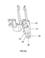
Der weitere Aufbau des Halteclipteils 21 umfasst in diesem Ausführungsbeispiel des weitern auch zwei Zapfen 38, die von den Seitenwänden 23, 24 des Grundkörpers entgegengesetzt zu den Federzungen 26 nach unten ragen. Ihre Länge entspricht ungefähr dem drei- bis sechsfachen der Dicke des verwendeten Blechs für den Halteclip.The further construction of the retaining
Diese Zapfen 38 dienen dazu, eine Reflektorscheibe 40, die im Prinzip eine Art Halbteller ist, und die im wesentlichen quer zur Lampenachse A angeordnet ist, zu arretieren, siehe dazu
Eine gleichartige Reflektorscheibe 40 ist auch auf dem zweiten Teilclip 21, der an dem anderen Ende der Quetschung montiert ist, angesetzt, so dass beide Halbteller zusammen eine mehr oder weniger vollständige reflektierende Abdeckung gegenüber dem Sockel bilden.A
Dazu sitzt am Grundkörper, hier im Bereich einer ersten Seitenwand 23 an dessen unterer Kante eine steigbügelartig geformte Einrastfeder 46. Diese hat einen starren Schenkel 47, der nach unten weg von der Kante der Seitenwand gerichtet ist, ein Brückenteil 48, das die Biegung bewerkstelligt, und einen etwa parallel zum starren Schenkel laufenden wieder zurückgebogenen freien, federnden Schenkel 49, der unterhalb des Zentriereinlaufs 28 endet. Insbesondere kann auch wie gezeigt eine Stabilisierungsplatte 50 am starren Schenkel 47 seitlich, insbesondere um 90° abgewinkelt, angesetzt sein, die sich in Richtung Tellerfuß 12 erstreckt und Abstand dazu wahrt.For this sits on the body, here in the region of a
Die Einrastfeder 46 drückt mit ihrem freien Schenkel 49 gegen die äußere Stromzuführung 11, wodurch der mechanische Kontakt dazu deutlich verbessert wird. Ein Laserschweißen für die Verbindung ist hier nicht unbedingt erforderlich, aber durchaus vorteilhaft.The
Ein Montageverfahren mit Hilfe des Halteclips läuft in folgenden Schritten ab: Zunächst wird der erste und zweite Clipteil und die Einbaulampe mit abgewinkelten äußeren Stromzuführungen bereitgestellt.An assembly process using the retaining clip is carried out in the following steps: First, the first and second clip part and the built-in lamp are provided with angled outer power supply lines.
Danach wird die Einbaulampe in den Halteclip gefügt, indem die Quetschung in die beiden Federzungen eingesetzt wird, wodurch sie fixiert ist, und wobei die Einbaulampe soweit zwischen die Federzungen geschoben wird, bis ihr Bodenteil der Quetschung auf dem Grundkörper bzw. dem Zentriereinlauf, aufliegt. Dabei werden gleichzeitig die Zuleitungen in die dafür vorgesehenen Andockstationen eingeklemmt.Thereafter, the integral lamp is inserted into the retaining clip by the pinch is inserted into the two spring tongues, whereby it is fixed, and wherein the integral lamp is pushed as far between the spring tongues until their bottom part of the pinch on the body or the centering, rests. At the same time the supply lines are clamped in the designated docking stations.
Danach wird die erste äußere Stromzuführung der Einbaulampe mit der Grundplatte durch Laserschweißen verbunden. Der Kontakt wird alternativ nur rein mechanisch bewerkstelligt, oder durch Widerstandsschweißen. Gleichzeitig oder zeitnah dazu wird auch die Andockstation mit der Zuleitung verschweißt, wenn der rein mechanische Kontakt als nicht ausreichend bewertet wird.Thereafter, the first external power supply of the integral lamp is connected to the base plate by laser welding. The contact is alternatively accomplished only purely mechanically, or by resistance welding. At the same time or in a timely manner, the docking station is also welded to the supply line if the purely mechanical contact is assessed as insufficient.
Ggf. wird nun eine Reflektorscheibe an jedes Clipteil angesetzt, sofern dies gewünscht wird bzw. sofern dieses nicht automatisch als integrales Teil bereits am Clipteil vorhanden war.Possibly. Now a reflector disc is attached to each clip part, if desired, or if this was not automatically available as an integral part already on the clip part.
Danach wird Kitt in die Sockelhülse 4 eingebracht und die Baueinheit Einbaulampe/Halteclip in die Sockelhülse gefügt, wobei der elektrische Kontakt zur Sockelhülse durch die beiden Zuleitungen sichergestellt werden.Thereafter, putty is introduced into the
Danach wird der Außenkolben 13 in die Sockelhülse eingepasst und der Kitt ausgeheizt. Die austretenden Gase werden dabei durch Unterdruck über den Bodenkontakt, der als Auge noch offen ist, abgesaugt. Danach wird ein Verlängerungsdraht einer Zuleitung bzw. eine Zuleitung selbst in Höhe des Bodenkontakts abgelängt und mit dem Bodenkontakt verlötet.Thereafter, the
Da der Grundkörper mit der Sockelhülse über eine erste Zuleitung elektrisch verbunden ist, wird damit der Seitenkontakt realisiert. Der Mittenkontakt wird dadurch realisiert, dass der Verlängerungsdraht im Bodenkontakt des Sockels, dem Auge, verlötet ist.Since the base body is electrically connected to the base sleeve via a first supply line, thus the side contact is realized. The center contact is realized by soldering the extension wire in the ground contact of the socket, the eye.
Als Sockel für die Lampe eignet sich selbstverständlich auch ein anderer Typ wie beispielsweise ein Bajonettsockel.As a base for the lamp is of course also another type such as a bayonet base.
Das Reflektorteil 40 selbst ist wie der Halteclip 21 beispielsweise aus Federstahl oder Federblech, wobei das Reflektorteil außerdem auch eine reflektierende Beschichtung auf seiner Oberseite aufweisen kann. Bevorzugt ist das Reflektorteil aus Aluminium, das hochglanzbeschichtet oder plattiert ist, gefertigt.The
Claims (12)
dem Grundkörper eine steigbügelartig geformte Einrastfeder zur Kontaktierung der abgebogenen äußeren Stromzuführung angesetzt ist, insbesondere mit einem starren Schenkel, der am Grundkörper befestigt ist, einem Brückenteil und einem freien Schenkel, der seitlich gegen die äußere Stromzuführung drückt.Lamp according to claim 1, characterized in that
the main body is a stirrup-like shaped latching spring for contacting the bent outer power supply is attached, in particular with a rigid leg which is fixed to the base body, a bridge part and a free leg which presses laterally against the outer power supply.
gemäß Anspruch 1, dadurch gekennzeichnet, dass in einem ersten Schritt ein Verlängerungsdraht mit einer zweiten äußeren Stromzuführung der Einbaulampe verbunden wird, danach die Einbaulampe mit dem Halteclip mechanisch verbunden wird, insbesondere zwischen mindestens zwei Federzungen der Schürze gefügt wird, danach die erste äußere Stromzuführung direkt mit der Schürze verbunden wird, insbesondere mittels eines an der Schürze ausgebildeten Wulstes, danach Kitt in die Sockelhülse eingebracht wird, danach die Baueinheit aus Einbaulampe und Halteclip in die Sockelhülse unter Kontaktnahme der Federfüße mit der Sockelhülse gefügt wird, danach der Außenkolben auf die Sockelhülse gefügt wird, danach der Kitt ausgeheizt wird und schließlich der Bodenkontakt mit dem Verlängerungsdraht verbunden wird.Method for producing an electric lamp
according to claim 1, characterized in that in a first step, an extension wire is connected to a second external power supply of the integral lamp, then the integral lamp is mechanically connected to the retaining clip, in particular between at least two spring tongues of the apron is joined, then the first external power supply is connected directly to the apron, in particular by means of a formed on the skirt bead, then putty is introduced into the base sleeve, then the assembly of built-in lamp and retaining clip is joined in the base sleeve by contacting the spring feet with the base sleeve, then the outer bulb is joined to the base sleeve, then the putty is baked and finally the ground contact is connected to the extension wire.
gemäß Anspruch 9 oder 10, dadurch gekennzeichnet, dass in einem ersten Schritt ein Verlängerungsdraht mit einer zweiten äußeren Stromzuführung der Einbaulampe verbunden wird, danach die Einbaulampe durch das Reflektorteil hindurchgefädelt wird und mit dem Halteclip mechanisch verbunden wird, insbesondere zwischen mindestens zwei Federzungen der Schürze gefügt wird, danach die erste äußere Stromzuführung direkt mit der Schürze verbunden wird, insbesondere mittels eines an der Schürze ausgebildeten Wulstes, danach Kitt in die Sockelhülse eingebracht wird, danach die Baueinheit aus Einbaulampe und Halteclip in die Sockelhülse unter Kontaktnahme der Federfüße mit der Sockelhülse gefügt wird, danach der Außenkolben auf die Sockelhülse gefügt wird, danach der Kitt ausgeheizt wird und schließlich der Bodenkontakt mit dem Verlängerungsdraht verbunden wird.Method for producing an electric lamp
according to claim 9 or 10, characterized in that in a first step, an extension wire is connected to a second external power supply of the built-in lamp, then the recessed lamp is threaded through the reflector part and is mechanically connected to the retaining clip, in particular between at least two spring tongues of the skirt joined Thereafter, the first external power supply is connected directly to the apron, in particular by means of a bead formed on the skirt, then putty is introduced into the base sleeve, then the assembly of built-in lamp and retaining clip is joined in the base sleeve by contacting the spring feet with the base sleeve , then the outer bulb on the base sleeve is then heated, then the putty is baked and finally the ground contact is connected to the extension wire.
Applications Claiming Priority (1)
| Application Number | Priority Date | Filing Date | Title |
|---|---|---|---|
| DE202011005637U DE202011005637U1 (en) | 2011-04-27 | 2011-04-27 | Electric lamp with an outer bulb and a built-in lamp |
Publications (2)
| Publication Number | Publication Date |
|---|---|
| EP2518754A2 true EP2518754A2 (en) | 2012-10-31 |
| EP2518754A3 EP2518754A3 (en) | 2013-01-02 |
Family
ID=44974199
Family Applications (1)
| Application Number | Title | Priority Date | Filing Date |
|---|---|---|---|
| EP12164505A Withdrawn EP2518754A3 (en) | 2011-04-27 | 2012-04-17 | Electric lamp with an external piston and a fitted lamp and production method |
Country Status (4)
| Country | Link |
|---|---|
| US (1) | US20120274199A1 (en) |
| EP (1) | EP2518754A3 (en) |
| CN (1) | CN102760637A (en) |
| DE (1) | DE202011005637U1 (en) |
Cited By (1)
| Publication number | Priority date | Publication date | Assignee | Title |
|---|---|---|---|---|
| DE102013223904A1 (en) * | 2013-11-22 | 2015-05-28 | Osram Gmbh | Electric lamp |
Families Citing this family (3)
| Publication number | Priority date | Publication date | Assignee | Title |
|---|---|---|---|---|
| IN2012DE02309A (en) * | 2012-07-25 | 2015-10-16 | Flowil Int Lighting | |
| DE102012219135A1 (en) | 2012-10-19 | 2014-04-24 | Osram Gmbh | Reflector lamp i.e. retrofit lamp, has assembly clip constructed from three portions, where first portion supports light source, second portion adjusts neck and comprises pillar-like side walls, and third portion is utilized for capping |
| CN115507335B (en) * | 2022-11-21 | 2023-01-24 | 保定来福汽车照明集团有限公司 | Automobile halogen lamp |
Citations (2)
| Publication number | Priority date | Publication date | Assignee | Title |
|---|---|---|---|---|
| DE3232207A1 (en) | 1982-08-30 | 1984-03-08 | Patent-Treuhand-Gesellschaft für elektrische Glühlampen mbH, 8000 München | HIGH PRESSURE DISCHARGE LAMP WITH LOW POWER |
| EP2239762A2 (en) | 2009-04-08 | 2010-10-13 | Osram Gesellschaft mit beschränkter Haftung | Electric lamp with an external piston and a fitted lamp |
Family Cites Families (13)
| Publication number | Priority date | Publication date | Assignee | Title |
|---|---|---|---|---|
| NL7018535A (en) * | 1969-12-29 | 1971-07-01 | ||
| JPS5737913Y2 (en) * | 1978-04-04 | 1982-08-20 | ||
| JPS6010436B2 (en) * | 1979-12-20 | 1985-03-16 | 株式会社東芝 | Manufacturing method of light source device |
| US4264117A (en) * | 1979-12-21 | 1981-04-28 | Amp Incorporated | Socket for wedge base incandescent lamp |
| US4769574A (en) * | 1986-08-04 | 1988-09-06 | Koito Seisakusho Co., Ltd. | Incandescent lamp with a metal coupling to a plastic lamp base for automotive headlamp and like lighting applications |
| HU202677B (en) * | 1989-03-10 | 1991-03-28 | Tungsram Reszvenytarsasag | Incandescent lamp |
| US6884118B2 (en) * | 2003-06-13 | 2005-04-26 | Christiana Industries, Llc | Lead aligning terminal |
| DE102004049500A1 (en) * | 2004-10-11 | 2006-04-20 | Patent-Treuhand-Gesellschaft für elektrische Glühlampen mbH | Lamp with built-in lamp |
| DE102004060918A1 (en) * | 2004-12-17 | 2006-06-22 | Patent-Treuhand-Gesellschaft für elektrische Glühlampen mbH | PAR lamp arrangement |
| DE202006004952U1 (en) * | 2006-03-28 | 2006-06-08 | Patent-Treuhand-Gesellschaft für elektrische Glühlampen mbH | Electric lamp with radiation protection clip |
| DE102007035595A1 (en) * | 2007-07-30 | 2009-02-05 | Osram Gesellschaft mit beschränkter Haftung | Electric lamp with an outer bulb and a built-in lamp and a method for its production |
| DE102008028383B4 (en) * | 2008-06-13 | 2019-12-24 | Ledvance Gmbh | Electric lamp with an outer bulb and a built-in lamp |
| DE202008016865U1 (en) * | 2008-12-19 | 2010-02-11 | Osram Gesellschaft mit beschränkter Haftung | Electric lamp with an outer bulb and a built-in lamp |
-
2011
- 2011-04-27 DE DE202011005637U patent/DE202011005637U1/en not_active Expired - Lifetime
-
2012
- 2012-04-17 EP EP12164505A patent/EP2518754A3/en not_active Withdrawn
- 2012-04-27 CN CN2012101297764A patent/CN102760637A/en active Pending
- 2012-04-27 US US13/457,528 patent/US20120274199A1/en not_active Abandoned
Patent Citations (2)
| Publication number | Priority date | Publication date | Assignee | Title |
|---|---|---|---|---|
| DE3232207A1 (en) | 1982-08-30 | 1984-03-08 | Patent-Treuhand-Gesellschaft für elektrische Glühlampen mbH, 8000 München | HIGH PRESSURE DISCHARGE LAMP WITH LOW POWER |
| EP2239762A2 (en) | 2009-04-08 | 2010-10-13 | Osram Gesellschaft mit beschränkter Haftung | Electric lamp with an external piston and a fitted lamp |
Cited By (2)
| Publication number | Priority date | Publication date | Assignee | Title |
|---|---|---|---|---|
| DE102013223904A1 (en) * | 2013-11-22 | 2015-05-28 | Osram Gmbh | Electric lamp |
| US9218952B2 (en) | 2013-11-22 | 2015-12-22 | Osram Gmbh | Electric lamp including a built-in-lamp having a pinch seal |
Also Published As
| Publication number | Publication date |
|---|---|
| DE202011005637U1 (en) | 2011-10-19 |
| EP2518754A3 (en) | 2013-01-02 |
| US20120274199A1 (en) | 2012-11-01 |
| CN102760637A (en) | 2012-10-31 |
Similar Documents
| Publication | Publication Date | Title |
|---|---|---|
| EP0897604A1 (en) | Halogen lamp with socket | |
| EP2518754A2 (en) | Electric lamp with an external piston and a fitted lamp and production method | |
| DE3609908A1 (en) | HALOGEN BULB AND METHOD FOR THEIR PRODUCTION | |
| EP1714306B1 (en) | Vehicle headlight bulb | |
| DE19842794A1 (en) | Electric reflector lamp for LV operation | |
| EP1672276B1 (en) | PAR-Lamp assembly | |
| EP2458614B1 (en) | Electric lamp with an outer bulb and a fitted lamp | |
| WO2006076879A1 (en) | High-pressure discharge lamp | |
| DE102008028383B4 (en) | Electric lamp with an outer bulb and a built-in lamp | |
| DE102010002769A1 (en) | Electric lamp with an outer bulb and a built-in lamp and associated manufacturing method | |
| WO2010069681A1 (en) | Electrical lamp having an outer bulb and a built-in lamp | |
| DE202009005396U1 (en) | Electric lamp with an outer bulb and a built-in lamp | |
| EP2399268A1 (en) | Electric lamp having an outer bulb and an installed lamp | |
| DE202011005509U1 (en) | Electric lamp with an outer bulb and a built-in lamp and associated manufacturing method | |
| DE102013223904A1 (en) | Electric lamp | |
| EP2201590A1 (en) | Built-in lamp with cable, in particular for aerodrome lighting | |
| DE102012219135A1 (en) | Reflector lamp i.e. retrofit lamp, has assembly clip constructed from three portions, where first portion supports light source, second portion adjusts neck and comprises pillar-like side walls, and third portion is utilized for capping | |
| DE2355637A1 (en) | ELECTRIC LAMP AND METHOD OF MANUFACTURING IT | |
| DE102010061964A1 (en) | Electric lamp i.e. high-volt halogen glow lamp, has retention clip with plate-like apron or base plate, which serves as stop for bottom part of pinch, and spring legs attached to base plate, and bearing arranged in base sleeve by legs | |
| DE19755171A1 (en) | Compact low pressure discharge lamp | |
| WO2006066534A2 (en) | Fastening method and lamp produced according to said method | |
| WO2008090040A2 (en) | Lamp | |
| WO2009059882A2 (en) | Electric lamp comprising an outer bulb and an integrated lamp | |
| DE10112690A1 (en) | Tungsten-halogen lamp for operating at mains voltage, has mount formed from single-piece support wire | |
| WO2008119623A1 (en) | Assembly for an electric lamp comprising an outer bulb |
Legal Events
| Date | Code | Title | Description |
|---|---|---|---|
| PUAI | Public reference made under article 153(3) epc to a published international application that has entered the european phase |
Free format text: ORIGINAL CODE: 0009012 |
|
| AK | Designated contracting states |
Kind code of ref document: A2 Designated state(s): AL AT BE BG CH CY CZ DE DK EE ES FI FR GB GR HR HU IE IS IT LI LT LU LV MC MK MT NL NO PL PT RO RS SE SI SK SM TR |
|
| AX | Request for extension of the european patent |
Extension state: BA ME |
|
| PUAL | Search report despatched |
Free format text: ORIGINAL CODE: 0009013 |
|
| AK | Designated contracting states |
Kind code of ref document: A3 Designated state(s): AL AT BE BG CH CY CZ DE DK EE ES FI FR GB GR HR HU IE IS IT LI LT LU LV MC MK MT NL NO PL PT RO RS SE SI SK SM TR |
|
| AX | Request for extension of the european patent |
Extension state: BA ME |
|
| RIC1 | Information provided on ipc code assigned before grant |
Ipc: H01K 1/48 20060101ALI20121123BHEP Ipc: H01J 5/60 20060101AFI20121123BHEP |
|
| RAP1 | Party data changed (applicant data changed or rights of an application transferred) |
Owner name: OSRAM GMBH |
|
| RAP1 | Party data changed (applicant data changed or rights of an application transferred) |
Owner name: OSRAM GMBH |
|
| STAA | Information on the status of an ep patent application or granted ep patent |
Free format text: STATUS: THE APPLICATION IS DEEMED TO BE WITHDRAWN |
|
| 18D | Application deemed to be withdrawn |
Effective date: 20130703 |