EP2518472B1 - Dispositif de mesure d'une image optique - Google Patents
Dispositif de mesure d'une image optique Download PDFInfo
- Publication number
- EP2518472B1 EP2518472B1 EP10838874.5A EP10838874A EP2518472B1 EP 2518472 B1 EP2518472 B1 EP 2518472B1 EP 10838874 A EP10838874 A EP 10838874A EP 2518472 B1 EP2518472 B1 EP 2518472B1
- Authority
- EP
- European Patent Office
- Prior art keywords
- light
- received
- light amount
- amount
- change
- Prior art date
- Legal status (The legal status is an assumption and is not a legal conclusion. Google has not performed a legal analysis and makes no representation as to the accuracy of the status listed.)
- Active
Links
- 230000003287 optical effect Effects 0.000 title claims description 89
- 238000005259 measurement Methods 0.000 title claims description 37
- 230000008859 change Effects 0.000 claims description 49
- 230000003595 spectral effect Effects 0.000 claims description 32
- 230000007423 decrease Effects 0.000 claims description 28
- 230000004044 response Effects 0.000 claims description 5
- 238000001228 spectrum Methods 0.000 claims description 3
- 238000012014 optical coherence tomography Methods 0.000 description 58
- 230000007246 mechanism Effects 0.000 description 41
- 238000012545 processing Methods 0.000 description 36
- 230000002207 retinal effect Effects 0.000 description 19
- 238000000034 method Methods 0.000 description 18
- 230000009471 action Effects 0.000 description 17
- 238000005286 illumination Methods 0.000 description 17
- 238000003384 imaging method Methods 0.000 description 15
- 238000003860 storage Methods 0.000 description 15
- 239000013307 optical fiber Substances 0.000 description 12
- 230000008569 process Effects 0.000 description 11
- 238000001514 detection method Methods 0.000 description 10
- 239000000835 fiber Substances 0.000 description 8
- 230000009467 reduction Effects 0.000 description 7
- 210000004087 cornea Anatomy 0.000 description 6
- 230000004907 flux Effects 0.000 description 6
- 238000012937 correction Methods 0.000 description 4
- 230000000694 effects Effects 0.000 description 4
- 238000012546 transfer Methods 0.000 description 4
- 238000004891 communication Methods 0.000 description 3
- 238000006073 displacement reaction Methods 0.000 description 3
- 230000006870 function Effects 0.000 description 3
- 210000004220 fundus oculi Anatomy 0.000 description 3
- 238000012544 monitoring process Methods 0.000 description 3
- 238000009877 rendering Methods 0.000 description 3
- 206010025421 Macule Diseases 0.000 description 2
- 239000006185 dispersion Substances 0.000 description 2
- 238000009826 distribution Methods 0.000 description 2
- 210000003733 optic disk Anatomy 0.000 description 2
- 239000004065 semiconductor Substances 0.000 description 2
- 230000000007 visual effect Effects 0.000 description 2
- 108010043121 Green Fluorescent Proteins Proteins 0.000 description 1
- 230000005540 biological transmission Effects 0.000 description 1
- 230000000295 complement effect Effects 0.000 description 1
- 238000004590 computer program Methods 0.000 description 1
- 238000005520 cutting process Methods 0.000 description 1
- 238000010586 diagram Methods 0.000 description 1
- 230000008030 elimination Effects 0.000 description 1
- 238000003379 elimination reaction Methods 0.000 description 1
- 230000004438 eyesight Effects 0.000 description 1
- 238000001914 filtration Methods 0.000 description 1
- 238000013534 fluorescein angiography Methods 0.000 description 1
- 210000001061 forehead Anatomy 0.000 description 1
- 229910052736 halogen Inorganic materials 0.000 description 1
- 150000002367 halogens Chemical class 0.000 description 1
- MOFVSTNWEDAEEK-UHFFFAOYSA-M indocyanine green Chemical compound [Na+].[O-]S(=O)(=O)CCCCN1C2=CC=C3C=CC=CC3=C2C(C)(C)C1=CC=CC=CC=CC1=[N+](CCCCS([O-])(=O)=O)C2=CC=C(C=CC=C3)C3=C2C1(C)C MOFVSTNWEDAEEK-UHFFFAOYSA-M 0.000 description 1
- 229960004657 indocyanine green Drugs 0.000 description 1
- 239000004973 liquid crystal related substance Substances 0.000 description 1
- 229910044991 metal oxide Inorganic materials 0.000 description 1
- 150000004706 metal oxides Chemical class 0.000 description 1
- 230000007935 neutral effect Effects 0.000 description 1
- 230000002093 peripheral effect Effects 0.000 description 1
- 230000010287 polarization Effects 0.000 description 1
- 230000000644 propagated effect Effects 0.000 description 1
- 230000001902 propagating effect Effects 0.000 description 1
- 230000035945 sensitivity Effects 0.000 description 1
- 230000007480 spreading Effects 0.000 description 1
- 238000003892 spreading Methods 0.000 description 1
- 238000010408 sweeping Methods 0.000 description 1
- 229910052724 xenon Inorganic materials 0.000 description 1
- FHNFHKCVQCLJFQ-UHFFFAOYSA-N xenon atom Chemical compound [Xe] FHNFHKCVQCLJFQ-UHFFFAOYSA-N 0.000 description 1
Images


Classifications
-
- A—HUMAN NECESSITIES
- A61—MEDICAL OR VETERINARY SCIENCE; HYGIENE
- A61B—DIAGNOSIS; SURGERY; IDENTIFICATION
- A61B3/00—Apparatus for testing the eyes; Instruments for examining the eyes
- A61B3/10—Objective types, i.e. instruments for examining the eyes independent of the patients' perceptions or reactions
- A61B3/102—Objective types, i.e. instruments for examining the eyes independent of the patients' perceptions or reactions for optical coherence tomography [OCT]
-
- G—PHYSICS
- G01—MEASURING; TESTING
- G01B—MEASURING LENGTH, THICKNESS OR SIMILAR LINEAR DIMENSIONS; MEASURING ANGLES; MEASURING AREAS; MEASURING IRREGULARITIES OF SURFACES OR CONTOURS
- G01B9/00—Measuring instruments characterised by the use of optical techniques
- G01B9/02—Interferometers
- G01B9/0209—Low-coherence interferometers
- G01B9/02091—Tomographic interferometers, e.g. based on optical coherence
-
- G—PHYSICS
- G01—MEASURING; TESTING
- G01N—INVESTIGATING OR ANALYSING MATERIALS BY DETERMINING THEIR CHEMICAL OR PHYSICAL PROPERTIES
- G01N21/00—Investigating or analysing materials by the use of optical means, i.e. using sub-millimetre waves, infrared, visible or ultraviolet light
- G01N21/17—Systems in which incident light is modified in accordance with the properties of the material investigated
- G01N21/47—Scattering, i.e. diffuse reflection
- G01N21/4795—Scattering, i.e. diffuse reflection spatially resolved investigating of object in scattering medium
Definitions
- the present invention relates to an optical image measurement apparatus configured to form images of a measured object by using optical coherence tomography (OCT).
- OCT optical coherence tomography
- OCT that forms images of the surface morphology and internal morphology of an object by using a light beam from a laser light source or the like has attracted attention.
- optical coherence tomography is noninvasive to human bodies, and is therefore expected to be utilized in the medical field and biological field.
- devices that form images of a fundus and cornea or the like are in a practical stage.
- Patent Document 1 discloses a device to which OCT is applied.
- This device has such a configuration that: a measuring arm scans an object by a rotary deflection mirror (a Galvano mirror); a reference arm is provided with a reference mirror; and an interferometer is mounted at the outlet to analyze, by a spectrometer, the intensity of an interference light of light fluxes from the measurement arm and the reference arm.
- the reference arm is configured to gradually change the light flux phase of the reference light by discontinuous values.
- the device of Patent Document 1 uses a technique of so-called "Fourier Domain OCT.” That is to say, the device irradiates a low-coherence light beam to an object, superposes the reflected light and the reference light to generate an interference light, and acquires the spectral intensity distribution of the interference light to execute Fourier transform, thereby imaging the morphology in the depth direction (the z-direction) of the object.
- the technique of this type is also called Spectral Domain.
- the device described in Patent Document 1 is provided with a Galvano mirror that scans with a light beam (a signal light), and is thereby configured to form an image of a desired measurement target region of the object. Because this device is configured to scan with the light beam only in one direction (the x-direction) orthogonal to the z-direction, an image formed by this device is a two-dimensional tomographic image in the depth direction (the z-direction) along the scanning direction (the x-direction) of the light beam.
- Patent Document 2 discloses a technique of scanning with a signal light in the horizontal direction (x-direction) and the vertical direction (y-direction) to form a plurality of two-dimensional tomographic images in the horizontal direction, and acquiring and imaging three-dimensional tomographic information of a measured range based on the tomographic images.
- the three-dimensional imaging for example, a method of arranging and displaying a plurality of tomographic images in the vertical direction (referred to as stack data or the like), and a method of executing a rendering process on a plurality of tomographic images to form a three-dimensional image are considered.
- Patent Document 4 describes an OCT device that irradiates a light having a predetermined beam diameter to an object and analyzes the components of an interference light obtained by superposing the reflected light and the reference light, thereby forming an image of the object in a cross-section orthogonal to the travelling direction of the light.
- Such an OCT device is called a full-field type, en-face type or the like.
- a fundus camera In addition, in the ophthalmologic field, before OCT was applied, a fundus camera, a slit lamp, etc. were used as devices for observing an eye (e.g., see Patent Documents 6 and 7).
- the fundus camera is a device that photographs the fundus oculi by projecting illumination light onto the eye and receiving the reflected light from the fundus oculi.
- the slit lamp is a device that obtains an image of the cross-section of the cornea by cutting off the light section of the cornea using slit light.
- the device with OCT is superior relative to the fundus camera, etc. in that high-definition images can be obtained, further in that tomographic images and three-dimensional images can be obtained, etc.
- OCT is a highly effective technique as described above, it is problematic in that it is difficult to properly maintain the received-light amount of interference light by the light-receiving part.
- This received-light amount corresponds to the intensity of the electric light output by the light-receiving part as a result of receiving interference light, also referred to as interference sensitivity.
- interference sensitivity the intensity of the electric light output by the light-receiving part as a result of receiving interference light
- Factors affecting the received-light amount include not only the relative positional relationship between the emission end of the light guiding part and the light-receiving surface of the light-receiving part described in Patent Document 5, but also the variation in various types of light involved in OCT, particularly the variation in the light amount of reference light, etc.
- This variation in the light amount results from displacement of optical members such as a reference mirror. Many of such displacements occur due to changes in the environment (particularly temperature changes) where the device is placed, so it is difficult to correct displacement of each optical member in each case.
- This invention resolves the above-mentioned problem, with the purpose of providing an optical image measurement apparatus capable of easily and quickly adjusting the received-light amount of interference light by the light-receiving part.
- an optical image measurement apparatus according to Claim 1 is provided.
- the optical image measurement apparatus related to the present invention based on the received-light amount of interference light by the light-receiving part, automatically performs a change of the relative position between the emission end of the light guiding part and the light-receiving surface of the light-receiving part, and a change of the light amount of signal light or reference light, respectively, and operates to lead the received-light amount of interference light by the light-receiving part to a target value. Therefore, it is possible to easily and quickly adjust the received-light amount of interference light by the light-receiving part.
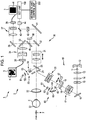
- a fundus observation apparatus (optical image measurement apparatus) 1, as shown in Fig. 1 and Fig. 2 , includes a retinal camera unit 2, an OCT unit 100, and an arithmetic and control unit 200.
- the retinal camera unit 2 has almost the same optical system as a conventional retinal camera.
- the OCT unit 100 is provided with an optical system for obtaining an OCT image of a fundus.
- the arithmetic and control unit 200 is provided with a computer that executes various arithmetic processes, control processes, and so on.
- the retinal camera unit shown in Fig. 1 is provided with an optical system for forming a 2-dimensional image (fundus image) representing the surface morphology of the fundus Ef of an eye E.
- Fundus images include observation images, photographed images, etc.
- the observation image is, for example, a monochrome moving image formed at a prescribed frame rate using near-infrared light.
- the observation image may be an image of an anterior eye part of the eye E.
- the photographed image is, for example, a color image captured by flashing visible light.
- the retinal camera unit 2 may also be configured so as to be capable of capturing other types of images such as a fluorescein angiography image, an indocyanine green fluorescent image, and an autofluorescent image.
- the retinal camera unit 2 is provided with a chin rest and a forehead placement for retaining the face of the subject, similar to a conventional retinal camera. Moreover, like a conventional retinal camera, the retinal camera unit 2 is provided with an illumination optical system 10 and an imaging optical system 30.
- the illumination optical system 10 irradiates an illumination light to the fundus Ef.
- the imaging optical system 30 guides a fundus reflected light of the illumination light to imaging devices (CCD image sensors 35, 38).
- the imaging optical system 30 guides a signal light LS coming from the OCT unit 100 to the fundus Ef, and guides the signal light propagated through the fundus Ef to the OCT unit 100.
- An observation light source 11 of the illumination optical system 10 comprises, for example, a halogen lamp.
- Light (observation illumination light) output from the observation light source 11 is reflected by a reflection mirror 12 with a curved reflection surface, and becomes near infrared after passing through a visible cut filter 14 via a condenser lens 13. Furthermore, the observation illumination light is once converged near an imaging light source 15, reflected by a mirror 16, and passes through relay lenses 17, 18, diaphragm 19, and relay lens 20. Then, the observation illumination light is reflected on the peripheral part (the surrounding region of an aperture part) of an aperture mirror 21 and illuminates the fundus Ef via an object lens 22.
- the fundus reflection light of the observation illumination light is refracted by the object lens 22, passes through the aperture part formed in the center region of the aperture mirror 21, passes through a dichroic mirror 55 and, travels through a focusing lens 31, and is reflected by a dichroic mirror 32. Furthermore, the fundus reflection light passes through a half-mirror 40 and forms an image on the light receiving surface of the CCD image sensor 35 by a condenser lens 34 after being reflected by a dichroic mirror 33.
- the CCD image sensor 35 detects, for example, the fundus reflection light at a prescribed frame rate.
- An image (observation image) K based on the fundus reflection light detected by the CCD image sensor 35 is displayed on a display device 3.
- An LCD (Liquid Crystal Display) 39 displays a fixation target or a visual target for measuring eyesight.
- the fixation target is a visual target for fixing the eye E, and is used when photographing a fundus or performing an OCT measurement.
- Part of the light output from the LCD 39 is reflected by a half-mirror 40, reflected by the dichroic mirror 32, passes through the aperture part of the aperture mirror 21 via the focusing lens 31 as well as a dichroic mirror 55, is refracted by the object lens 22 and projected to the fundus Ef.
- fixation position of the eye E there are a position for acquiring an image centered on the macula of the fundus Ef, a position for acquiring an image centered on the optic papilla, a position for acquiring an image centered on the fundus center between the macula and the optic papilla, and so on, for example, as in conventional retinal cameras.
- Light (alignment light) output from the LED (Light Emitting Diode) 51 of the alignment optical system 50 is reflected by the dichroic mirror 55 via diaphragms 52, 53 and a relay lens 54, passes through the aperture part of the aperture mirror 21, and is projected onto the cornea of the eye E by the object lens 22.
- Part of cornea reflection light of the alignment light is transmitted through the dichroic mirror 55 via the object lens 22 and the aperture part, passes through the focusing lens 31, is reflected by the dichroic mirror 32, transmitted through the half-mirror 40, reflected by the dichroic mirror 33, and projected onto the light receiving surface of the CCD image sensor 35 by the condenser lens 34.
- An image (alignment target) captured by the CCD image sensor 35 is displayed on the display device 3 along with the observation image K.
- a user conducts alignment by an operation that is the same as conventional fundus cameras. It should be noted that alignment may be performed, by an arithmetic and control unit 200, as a result of analyzing the position of the alignment target and moving the optical system.
- the reflection surface of a reflection rod 67 is provided in a slanted position on the light path of the illumination optical system 10.
- Light (focus light) output from an LED 61 of the focus optical system 60 passes through a relay lens 62, is split into two light fluxes by a split target plate 63, passes through a two-hole diaphragm 64, is reflected by a mirror 65, and is reflected after an image is formed once on the reflection surface of the reflection rod 67 by a condenser lens 66.
- the focus light is reflected at the aperture mirror 21 via the relay lens 20 and an image is formed on the fundus Ef by the object lens 22.
- the fundus reflection light of the focus light passes through the same route as the cornea reflection light of the alignment light and is detected by the CCD image sensor 35.
- a light (split target) captured by the CCD image sensor 35 is displayed on the display device 3 along with an observation image K.
- the arithmetic and control unit 200 analyzes the position of the split target, and moves the focusing lens 31 and the focus optical system 60 for focusing. It should be noted that focusing may be performed manually while visually recognizing the split target.
- An optical path including a mirror 41, collimator lens 42, and Galvano mirrors 43, 44 is provided behind the dichroic mirror 32.
- the optical path is connected to the OCT unit 100.
- the Galvano mirror 44 performs scanning with a signal light LS from the OCT unit 100 in the x-direction.
- the Galvano mirror 43 performs scanning with a signal light LS in the y-direction. Scanning may be performed with the signal light LS in an arbitrary direction in the xy-plane due to the two Galvano mirrors 43 and 44.
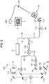
- the OCT unit 100 is provided with an optical system for obtaining a tomographic image of the fundus Ef (see Fig. 2 ).
- the optical system has a similar configuration to a conventional Fourier-Domain-type OCT device. That is to say, the optical system is provided with an interferometer configured to split low-coherence light into signal light and reference light and generates interference light by superposing the signal light that has passed through the fundus Ef and the reference light that has passed through a reference optical path. Furthermore, the optical system is configured to detect the spectral components of the interference light generated by the interferometer. This detection result (detection signal) is transmitted to the arithmetic and control unit 200.
- a light source unit 101 outputs a broadband low-coherence light L0.
- the low-coherence light L0 for example, includes near-infrared wavelength bands (about 800-900nm) and has a coherence length of about tens of micrometer.
- near-infrared light having wavelength bands that are impossible to be detected by human eyes for example, infrared light having the center wavelength of about 1050-1060nm.
- the light source unit 101 is configured to include light output device, such as an SLD (super luminescent diode), SOA (Semiconductor Optical Amplifier) and the like.
- SLD super luminescent diode
- SOA semiconductor Optical Amplifier
- the low-coherence light L0 output from the light source unit 101 is guided to a fiber coupler 103 by an optical fiber 102 and split into signal light LS and reference light LR.
- the fiber coupler 103 acts both as a means to split light (splitter) as well as a means to synthesize light (coupler), but herein the same is conventionally referred to as a "fiber coupler.”
- the signal light LS is guided by the optical fiber 104 and becomes a parallel light flux by a collimator lens unit 105. Furthermore, the signal light LS is reflected by Galvano mirrors 44 and 43, converged by the collimator lens 42, reflected by the mirror 41, transmitted through a dichroic mirror 32, and irradiated to the fundus Ef after passing through a route that is the same as the light from the LCD 39.
- the signal light LS is scattered and reflected at the fundus Ef.
- the scattered light and the reflection light are sometimes all together referred to as the fundus reflection light of the signal light LS.
- the fundus reflection light of the signal light LS progresses along the same route in the reverse direction and is guided to the fiber coupler 103.
- the reference light LR is guided by an optical fiber 106 and becomes a parallel light flux by a collimator lens unit 107. Furthermore, the reference light LR is reflected by mirrors 108, 109, 110, passed through an attenuator 121, dimmed by an ND (Neutral Density) filter 111, and reflected by a mirror 112, with the image formed on a reflection surface of a reference mirror 114 by a collimator lens 113. The reference light LR reflected by the reference mirror 114 progresses along the same route in the reverse direction and is guided to the fiber coupler 103. It should be noted that an optical element for dispersion compensation (pair prism, etc.) and/or an optical element for polarization correction (wave plate, etc.) may also be provided for the optical path (reference optical path) of the reference light LR.
- reference light LR passing through the attenuator 121 is a parallel pencil.
- the attenuator 121 is a device that changes the light amount of the reference light LR.
- the attenuator 121 is configured to change the amount of light by shielding part of the cross-section of the reference light LR.
- the attenuator 121 is equipped with a shielding member that can be inserted and removed relative to the optical path of the reference light LR, as well as a drive part that moves this shielding member.
- the drive part includes, for example, a stepping motor.
- the drive part is controlled by an arithmetic and control unit 200 to gradually change the position of the shielding member.
- the shielding member gradually shields the cross-section of the reference light LR. That is, the attenuator 121 can gradually change the light amount of the reference light LR.
- a shield region made by the shielding member in the cross-section of the reference light LR is changed.
- the configuration of the attenuator 121 is not limited to that described above. It is possible to apply an attenuator of any known configuration to the present invention.
- the attenuator 121 is for changing the light amount of interference light LC projected onto a CCD image sensor 120 by changing the light amount of the reference light LR, which is an example of a "second changing part" in the present invention.
- the fiber coupler 103 superposes the fundus reflection light of the signal light LS and the reference light LR reflected by the reference mirror 114.
- Interference light LC thus generated is guided by an optical fiber 115 and output from an exit end 116.
- the interference light LC is converted to a parallel light flux by a collimator lens 117, spectrally divided (spectrally decomposed) by a diffraction grating 118, converged by the convergence lens 119, and projected onto the light receiving surface of a CCD image sensor 120.
- the diffraction grating 118 shown in Fig. 2 is of the transmission type, but the reflection type can also be used.
- the CCD image sensor 120 is for example a line sensor (image sensor in which multiple CCD elements are arranged one-dimensionally), and detects the respective spectral components of the spectrally decomposed interference light LC and converts the components into electric charges.
- the CCD image sensor 120 accumulates these electric charges and generates a detection signal. Furthermore, the CCD image sensor 120 transmits the detection signal to the arithmetic and control unit 200.
- CCD image sensor 120 may be an area sensor (image sensor in which multiple CCD elements are arranged two-dimensionally). In this case, predefined CCD elements that are arranged one-dimensionally among the multiple CCD elements are used to detect spectral components.
- the optical fiber 115 is an example of a "light guiding part" of the present invention.
- the diffraction grating 118 is an example of a “spectral part” of the present invention.
- the CCD image sensor 120 is an example of a "light-receiving part” of the present invention.
- the emission end 116 of the optical fiber 115 is configured to be movable. This is described as follows. With OCT measurement, it is necessary to accurately project the spectral components of the interference light relative to CCD elements comprising the CCD image sensor 120. Therefore, it is necessary to conform the direction of the arrangement of the CCD elements and the spreading direction of the spectral components of the interference light LC as much as possible and adjust the relative positional relationship between the emission end 116 and the light-receiving surface of the CCD image sensor 120 so that each CCD element accurately receives the spectral components to be received.
- this relative position is changed by changing the position of the emission end 116.
- a fiber-end drive mechanism is described in Patent Document 5.
- this fiber-end drive mechanism is to be used (indicated by the symbol 140).
- the fiber-end drive mechanism 140 is configured to include an actuator such as a stepping motor, and a transfer mechanism that transfers the drive force output by this actuator, for example.
- This transfer mechanism is connected to, for example, a site of the optical fiber 115 other than its end face (i.e., the interference light LC emission end face) and transfers the drive force developed by the actuator to the emission end 116.
- the fiber-end drive mechanism 140 moves the emission end 116 in the direction parallel to the end face of the optical fiber 115 or in the direction perpendicular to the end face. Therefore, the emission end 116 is moved three-dimensionally with the direction of the end face fixed. Furthermore, the fiber-end drive mechanism 140 moves the position of the emission end 116 to change the direction of the end face.
- the fiber-end drive mechanism 140 may change the relative positional relationship alone, the relative direction alone, or possibly both.
- the configuration to change the position of the emission end 116 is employed, in place of this, it is also possible to employ the configuration to change the position of the CCD image sensor 120. Moreover, it is also possible to change both the position of the emission end 116 and the position of the CCD image sensor 120.
- the fiber-end drive mechanism 140 is an example of the "first changing part" in the present invention.
- the fiber-end drive mechanism 140 changes the relative position between the emission end 116 and the light-receiving surface by moving the emission end 116 in the direction intersecting the direction of the arrangement of the CCD elements.
- the "intersecting direction” is, for example, the direction perpendicular to the direction of the arrangement.
- the fiber-end drive mechanism 140 may have a function to rotate the emission end 116 around the axial direction of the optical fiber 115.
- CMOS Complementary Metal Oxide Semiconductor
- the second changing part is established in the reference optical path.
- the device is used in the ophthalmologic field. That is, considering there is a limitation on the light amount of illumination light (herein the signal light LS) in order to avoid damage to the eye, in addition to the fact that the signal light LS reflected from the fundus oculi is weak, it is necessary to maintain the proper light amount of the reference light LR. When the light amount of the reference light LR is too much, compared to that of the signal light LS, subtle information included in the signal light LS is masked by the reference light LR and suitable interference light LC cannot be obtained.
- the attenuator 121 is disposed in the reference optical path to adjust the light amount of the reference light LR.
- the device related to the present invention is used in other fields, it is also possible to establish a second changing part in the signal optical path. Moreover, it is also possible to establish a second changing part in the optical path for low-coherence light L0 or interference light LC. If a second changing part is established in the low-coherence light L0, for example, the second changing part can be disposed to change the light amount of low-coherence light L0 (which is desirably a parallel pencil) emitting from the light source unit 101 and propagating through the space, and configured to cause the low-coherence light L0 that has passed through this to enter the optical fiber 102.
- low-coherence light L0 which is desirably a parallel pencil
- the second changing part can be disposed between the fiber coupler 103 and a spectrometer (i.e., diffraction grating 118) (which is desirably a position where the interference light LC is a parallel pencil).
- the second changing part may be respectively established in at least two optical paths for the low-coherence light L0, signal light LS, reference light LR, and interference light LC.
- the second changing parts may be controlled independently or all operations may be linked.
- the arithmetic and control unit 200 analyzes the detection signals inputted from the CCD image sensor 120, and forms an OCT image of the fundus Ef.
- An arithmetic process for this is the same as that of a conventional Fourier-Domain-type OCT device.
- the arithmetic and control unit 200 controls each part of the retinal camera unit 2, the display device 3 and the OCT unit 100.
- the arithmetic and control unit 200 causes an OCT image such as a tomographic image G (see Fig. 2 ) of the fundus Ef to be displayed on the display device 3.
- the arithmetic and control unit 200 executes: control of action of the observation light source 101, the imaging light source 103 and LED's 51 and 61; control of action of the LCD 39; control of movement of the focusing lens 31; control of movement of the reflection rod 67; control of movement of the focus optical system 60; control of action of the respective Galvano mirrors 43 and 44; and so on.
- the arithmetic and control unit 200 executes: control of action of the light source unit 101; control of movement of the reference mirror 114 and the collimator lens 113; control of action of the CCD image sensor 120; control of action of the attenuator 121; control of action of the fiber-end drive mechanism 140; and so on.
- the arithmetic and control unit 200 includes a microprocessor, a RAM, a ROM, a hard disk drive, a communication interface, and so on, as in conventional computers.
- the storage device such as the hard disk drive stores a computer program for controlling the fundus observation apparatus 1.
- the arithmetic and control unit 200 may be provided with a circuit board dedicated for forming OCT images based on detection signals from the CCD image sensor 120.
- the arithmetic and control unit 200 may be provided with operation devices (input devices) such as a keyboard and a mouse, and/or display devices such as LCD.
- the retinal camera unit 2, display device 3, OCT unit 100, and arithmetic and control unit 200 may be integrally configured (that is, within a single case), or configured as separate bodies.
- the control system of the fundus observation apparatus 1 has a configuration centered on a controller 210 of the arithmetic and control unit 200.
- the controller 210 includes, for example, the aforementioned microprocessor, RAM, ROM, hard disk drive, and communication interface.
- the controller 210 is provided with a main controller 211 and storage 213.
- the main controller 211 performs the aforementioned various kinds of control. Specifically, the main controller 211 controls a scan driver 70 as well as a focus driver 80 of the retinal camera unit 2, and further controls a reference driver 130, the attenuator 121 and the fiber-end drive mechanism 140 of the OCT unit 100.
- the main controller 211 is an example of a "controller" of the invention.
- the scan driver 70 is configured, for example, including a servo motor and independently changes the facing direction of the Galvano mirrors 43 and 44.
- the focus driver 80 is configured, for example, including a pulse motor and moves the focusing lens 31 in the optical axis direction. Thereby, the focus position of light towards the fundus Ef is changed.
- the reference driver 130 is configured, for example, including a pulse motor and integrally moves the collimator lens 113 as well as the reference mirror 114 along the travelling direction of the reference light LR.
- the main controller 211 controls the fiber-end drive mechanism 140 based on the received-light amount that is specified by a received-light-amount specifying part 212 described later. Thereby, the main controller 211 moves the emission end 116 to increase the received-light amount (i.e., the relative position between the emission end 116 and the light-receiving surface is changed).
- This processing corresponds to more properly projecting the spectral components of the interference light LC onto the light-receiving surface, i.e., correcting the position of projecting the spectral components onto the light-receiving surface.
- the main controller 211 controls the attenuator 121 based on the received-light amount that is specified by the received-light-amount specifying part 212. Thereby, the main controller 211 moves the shielding member of the attenuator 121 and changes the shield region in the cross-section of the reference light LR. This processing corresponds to changing the light amount of the reference light LR contributing to the generation of the interference light LC.
- the main controller 211 executes a process of writing data into the storage 213, and a process of reading out the data from the storage 213.
- the main controller 211 is equipped with the received-light-amount specifying part 212.
- the received-light-amount specifying part 212 specifies the amount of the interference light LC received by the CCD image sensor 120 based on the signal (aforementioned detection signal) output from the CCD image sensor 120.
- the received-light-amount specifying part 212 is an example of the "specifying part" in the present invention.
- the received-light amount is affected by the light amount of the interference light LC and the projection status of the interference light LC relative to the light-receiving surface of the CCD image sensor 120.
- the adjustment operations for these two factors are linked to obtain a suitable received-light amount.
- the light amount of the interference light LC is determined by the light amount of the signal light LS and the light amount of the reference light LR.
- the light amount of the signal light LS is not adjusted, so the light amount of the interference light LC reflects the light amount of the reference light LR.
- the light amount of the reference light LR is adjusted by the attenuator 121 as described previously.
- the projection status of the interference light LC relative to the light-receiving surface includes the projection position of the interference light LC relative to the light-receiving surface of the CCD image sensor 120, as well as the projection direction of the interference light LC relative to the light-receiving surface. In addition, only one of these may be taken into account.
- the projection position of the interference light LC relative to the light-receiving surface is displaced, some or all of the CCD elements arranged on the light-receiving surface may not receive the interference light LC. Thus, some or all of the spectral components of the interference light LC may not be detected and proper OCT images cannot be formed.
- each spectral component of the interference light LC enters from an improper direction relative to the CCD elements arranged on the light-receiving surface.
- the received-light amount of a spectral component received that is detected by each CCD element no longer reflects the actual light amount (intensity) and no proper OCT images can be formed.
- the adjustment of the light amount of the reference light LR i.e., the light amount of the interference light LC
- the adjustment of the projection status of the interference light LC relative to the light-receiving surface while monitoring the received-light amount of the interference light LC, it is attempted to ease and accelerate the adjustment operation for the received-light amount of the interference light LC by the CCD image sensor 120.
- the storage 213 stores various kinds of data.
- the data stored in the storage 213 is, for example, image data of OCT images, image data of fundus images, and eye information.
- the eye information includes information on the eye, for example, information on a subject such as a patient ID and a name, information on identification of left eye or right eye, and so on.
- control program 214 is stored in the storage 213 in advance.
- the main controller 211 causes characteristic actions (described latter) of the present embodiment to be performed by controlling each part of the apparatus based on the control program 214.
- An image forming part 220 forms image data of a tomographic image of the fundus Ef based on the detection signals from the CCD image sensor 120.
- this process includes processes such as noise elimination (noise reduction), filtering, and FFT (Fast Fourier Transform).
- the image forming part 220 includes, for example, the aforementioned circuit board and communication interface. It should be noted that “image data” and the “image” presented based on the image data may be identified with each other in this specification.
- the image forming part 220 is an example of an "image forming part" of the present invention.
- the image forming part may include an image processor 230 (in particular, its part forming three-dimensional images and tomographic images) as described later.
- An image processor 230 executes various image processing and analysis on images formed by the image forming part 220.
- the image processor 230 executes various correction processes such as luminance correction and dispersion correction of images.
- the image processor 230 executes, for example, an interpolation process of interpolating pixels between tomographic images formed by the image forming part 220, thereby forming image data of a three-dimensional image of the fundus Ef.
- Image data of a three-dimensional image refers to image data that the positions of pixels are defined by the three-dimensional coordinates.
- the image data of a three-dimensional image is, for example, image data composed of three-dimensionally arranged voxels. This image data is referred to as volume data, voxel data, or the like.
- the image processor 230 executes a rendering process (such as volume rendering and MIP (Maximum Intensity Projection)) on this volume data, and forms image data of a pseudo three-dimensional image taken from a specific view direction. On a display device such as the display 240, this pseudo three-dimensional image is displayed.
- a rendering process such as volume rendering and MIP (Maximum Intensity Projection)
- stack data of a plurality of tomographic images is image data obtained by three-dimensionally arranging a plurality of tomographic images obtained along a plurality of scanning lines, based on the positional relation of the scanning lines. That is to say, stack data is image data obtained by expressing a plurality of tomographic images defined by originally individual two-dimensional coordinate systems by a three-dimensional coordinate system (namely, embedding into a three-dimensional space).
- the image processor 230 can form a tomographic image in any cross-section based on the image data of a three-dimensional image.
- This processing is executed, for example, by specifying, for the cross-section manually or automatically designated, a picture element (such as a voxel) located on this cross-section and arranging the specified image elements two-dimensionally to form image data that represents the morphology of the fundus Ef in the cross-section.
- a picture element such as a voxel
- the image processor 230 includes, for example, the aforementioned microprocessor, RAM, ROM, hard disk drive, circuit board, and so on.
- the display 240 is configured including various types of display devices such as the display device 3.
- the operation part 250 is configured including an operation device equipped with the arithmetic and control unit 200, and various kinds of operation devices provided with the case of the fundus observation apparatus 1 or its outside.
- the display 240 and the operation part 250 do not need to be composed as separate devices.
- a device in which the display function and the operation function are integrated can be used.
- the scan aspect of the signal light LS by the fundus observation apparatus 1 is, for example, a horizontal scan, vertical scan, cruciform scan, radial scan, circular scan, concentric scan, and helical scan. These scan aspects are selectively used as necessary in consideration of an observation site of the fundus, an analysis target (the retinal thickness or the like), a time required to scan, the accuracy of a scan, and so on.
- a horizontal scan is a scan with the signal light LS in the horizontal direction (x-direction).
- the horizontal scan includes an aspect of scanning with the signal light LS along a plurality of scanning lines extending in the horizontal direction arranged in the vertical direction (y-direction). In this aspect, it is possible to set any interval between scanning lines. By setting the interval between adjacent scanning lines to be sufficiently narrow, it is possible to form the aforementioned three-dimensional image (three-dimensional scan).
- a vertical scan is also performed in a similar manner.
- a cruciform scan is a scan with the signal light LS along a cross-shape trajectory formed by two linear trajectories (line trajectories) orthogonal to each other.
- a radial scan is a scan with the signal light LS along a radial trajectory formed by a plurality of line trajectories arranged at predetermined angles.
- the cruciform scan is an example of the radial scan.
- a circular scan is a scan with the signal light LS along a circular trajectory.
- a concentric scan is a scan with the signal light LS along a plurality of circular trajectories arranged concentrically around a predetermined center position.
- the circular scan is an example of the concentric scan.
- a helical scan is a scan with the signal light LS along a helical trajectory while making the turning radius gradually smaller (or greater).
- the Galvano mirrors 43 and 44 are configured to scan the signal light LS in the directions orthogonal to each other, they are capable of scanning with the signal light LS in the x-direction and the y-direction independently. Moreover, it is possible to scan with the signal light LS along an arbitrary trajectory on the xy-plane by simultaneously controlling the directions of the Galvano mirrors 43 and 44. Thus, it is possible to realize various types of scan aspects as described above.
- a region on the fundus Ef subjected to scanning by the signal light LS as above, that is a region on the fundus Ef subjected to OCT measurement, is referred to as a scanning region.
- a scanning region in three-dimensional scanning is a rectangular-shaped region in which multiple horizontal scans are arranged.
- a scanning region in a concentric circular scan is a disc-shaped region surrounded by the trajectories of a circular scan of a maximum diameter.
- the scanning region in a radial scan is a disc-shaped (or polygonal-shaped) region linking end positions of scanning lines.
- the operation of the fundus observation apparatus 1 is described.
- the following operation is performed at a predefined timing before measurement.
- the following operation is performed before shipment, at the time of starting (at the time of power-up), at the time of changing a subject.
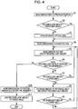
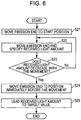
- a first operational example is described with reference to Fig. 4 and Fig. 5 .
- the main controller 211 controls the fiber-end drive mechanism 140 to move the emission end 116 to the position in the previous examination (S1). This processing is executed as follows, for example.
- the main controller 211 stores the information indicating the position of the emission end 116 at that time in the storage 213. Every time it adjusts the position of the emission end 116, it may store the information indicating the position after the adjustment.
- the main controller 211 reads this information from the storage 213 and controls the fiber-end drive mechanism 140 so as to dispose the fiber-end drive mechanism 140 in that position.
- Step 2 the main controller 211 checks if the received-light amount by the CCD image sensor 120 in this status exceeds a predefined value (S2).
- This predefined value is an arbitrary preset value for determining whether or not the received-light amount is insufficient. This predefined value is set to a lower limit in a predefined range described later, for example.
- the processing of Step 2 is executed as follows, for example.
- the main controller 211 controls the light source unit 101 to cause low-coherence light L0 to be output.
- the reference light LR based on the low-coherence light L0 reaches the diffraction grating 118 via the reference optical path, fiber coupler 103, optical fiber 115, etc.
- the diffraction grating 118 divides the reference light LR into spectra.
- the spectral components thereof are projected onto the light-receiving surface of the CCD image sensor 120.
- the CCD image sensor 120 that has received the spectral components sends a detection signal to the arithmetic and control unit 200.
- the received-light-amount specifying part 212 obtains the received-light amount based on this detection signal.
- the main controller 211 determines whether the obtained received-light amount exceeds a predefined value.
- the received-light-amount specifying part 212 obtains the received-light amount of this synthetic light and the main controller 211 determines whether this received-light amount exceeds a predefined value.
- the main controller 211 controls the attenuator 121 to open the reference optical path, i.e., release the shield against the reference light LR (S3). More specifically, the main controller 211 controls the drive part of the attenuator 121 to retreat the shielding member from the reference optical path.
- the main controller 211 controls the fiber-end drive mechanism 140 to move the emission end 116 to a start position (S4).
- This start position is, for example, a predefined position in the direction perpendicular to the direction of the arrangement of the CCD elements.
- the emission end 116 is moved in the perpendicular direction.
- This moving direction is considered to be the direction in which the received-light amount should increase.
- the opposite direction will be the subsequent moving direction.
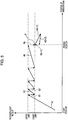
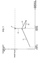
- the start position is shown in Fig. 5 .
- the moving direction is the direction indicated by the horizontal axis (emission end position) in Fig. 5 . Reference is made to Fig. 5 in the following.
- the main controller 211 controls the fiber-end drive mechanism 140 to sequentially move the emission end 116 while causing the received-light-amount specifying part 212 to sequentially execute the processing to specify the received-light amount (S5).
- the received-light amount increases with the movement of the emission end 116 (S6: No). It is when the projection positions of the spectral components passes through the CCD elements that the received-light amount starts to decrease with the movement of the emission end 116.
- the operation in which the fiber-end drive mechanism 140 moves the emission end 116 in a predefined direction (the aforementioned moving direction) by a predefined distance and the operation in which the received-light-amount specifying part 212 specifies the received-light amount, are performed alternately.
- the former operation is executed by, for example, sending a predefined pulse number signal to the stepping motor of the fiber-end drive mechanism 140 to drive it.
- the operation is repeatedly performed in which, as the emission end 116 is moved by the predefined distance, the received-light amount is obtained, and as the emission end 116 is further moved by the predefined distance, the received-light amount is obtained.
- This operation is repeated until the obtained received-light amount is equal to or more than the upper limit (S7: No). This operation is indicated by the symbol A1 in Fig. 5 .
- this upper limit is the maximum value in a predefined range that has been preset.
- This predefined range can be arbitrarily set to the extent that it does not substantially depart from the target value for the received-light amount.
- This target value is an approximately optimal value for the received-light amount, which is the final value achieved that is led by this operational example. This target value is preset.
- the main controller 211 stops the operation of the fiber-end drive mechanism 140 and controls the attenuator 121 to decrease the light amount of reference light LR (S8).
- the light amount of interference light LC decreases and the received-light amount by the CCD image sensor 120 decreases.
- This is the operation indicated by the symbol B1.
- the processing to decrease the light amount of reference light LR by a predefined amount and the processing to specify the received-light amount are repeatedly performed.
- the former processing is executed by, for example, sending a predefined pulse number signal to the stepping motor of the attenuator 121 to drive it. This operation is repeated until the obtained received-light amount becomes equal to or less than the lower limit (S9: No).
- the main controller 211 stops the operation of the attenuator 121 and controls the fiber-end drive mechanism 140 to restart the movement of the emission end 116 (S5).
- the operation indicated by the symbol A2, the operation indicated by the symbol B2, ⁇ , the operation indicated by the symbol Ak, and the operation indicated by the symbol Bk are sequentially executed.
- Steps 5 through 9 The processing in Steps 5 through 9 is repeated until the received-light amount decreases with the movement of the emission end 116 (S6: No).
- the fact that the received-light amount has started to decrease with the movement of the emission end 116 means that the projection positions of the spectral components of the interference light LC has passed through the CCD elements of the CCD image sensor 120.
- the received-light amount decreases temporarily due to the effect of noise, etc., it may be determined whether or not the received-light amount continues to decrease while moving the emission end 116 by a certain distance.
- the main controller 211 controls the fiber-end drive mechanism 140 and reverses the moving direction of the emission end 116 to move the emission end 116 to the position immediately before the movement (i.e., the position where the received-light amount has started to decrease) (S10).
- the emission end 116 is disposed in a proper position shown in Fig. 5 .
- This proper position is the position of the emission end 116 that realizes a status in which the spectral components of the interference light LC are properly projected onto the CCD elements.
- the main controller 211 controls the attenuator 121 and leads the received-light amount to a target value P (S11). This is the operation indicated by the symbol B(k+1). This completes the processing related to this operational example.
- the fundus observation apparatus 1 performs OCT measurement and forms an OCT image of the fundus Ef.
- the predefined range shown in Fig. 5 corresponds to the range of reduction of the received-light amount by the attenuator 121.
- this range of reduction becomes larger.
- the number of times to repeat Steps 5 through 9 is reduced, and the accuracy of the processing to look for the proper position of the emission end 116 is reduced.
- narrowing the predefined range makes this range of reduction smaller. In this case, in general, the number of repetitions increases, and the accuracy of the processing is improved.
- a user can set the predefined range as appropriate by taking into account these items, needs in the examination, etc.
- the range of reduction of the received-light amount by the attenuator 121 is constant but not limited to this.
- the predefined range so that the upper limit and/or lower limit increases or decreases depending on the position of the emission end 116 (horizontal axis in Fig. 5 ).
- it is possible to set the predefined range so as to widen the range of reduction to attempt to reduce the examination time at the beginning of the repetition and also gradually diminish the range of reduction to attempt to improve the processing accuracy.
- the main controller 211 controls the fiber-end drive mechanism 140 and moves the emission end 116 to the start position (S21).
- the main controller 211 while causing the received-light-amount specifying part 212 to sequentially execute the processing to specify the received-light amount, controls the fiber-end drive mechanism 140 and sequentially moves the emission end 116 (S22). As described previously, at least during the initial stage, the moving direction of the emission end 116 is set to the direction to increase the received-light amount. Step 22 corresponds to the operation indicated by the symbol C1.
- the main controller 211 controls the fiber-end drive mechanism 140 and reverses the moving direction of the emission end 116 to move the emission end 116 to the position just prior to the movement (i.e., the position where the received-light amount has started to decrease) (S24). This is the operation indicated by the symbol C3. With this operation, the emission end 116 is disposed in a proper position shown in Fig. 7 . This proper position is the position of the emission end 116 that realizes the status in which the spectral components of the interference light LC are properly projected on the CCD elements.
- the main controller 211 controls the attenuator 121 and leads the received-light amount to a target value P (S25). This is the operation indicated by the symbol D1. This completes the processing related to this operational example.
- the fundus observation apparatus 1 performs OCT measurement and forms an OCT image of the fundus Ef after such adjustment processing of the received-light amount is finished.
- this operational example it is possible to automatically adjust the position of the emission end 116 so that the spectral components of the interference light LC are properly projected on the CCD elements and further automatically tailor the received-light amount to the target value.
- this operational example is effective if the specified received-light amount is relatively small (e.g., if the shield region by the attenuator 121 is relatively large at the initial stage).
- the main controller 211 controls the fiber-end drive mechanism 140 and moves the emission end 116 to the start position (S31).
- the main controller 211 alternately and repeatedly executes the processing to specify the received-light amount and the movement of the emission end 116 (S32, S33: No). This corresponds to the operation indicated by the symbol F1.
- the main controller 211 stores the information (first positional information) representing the position of the emission end 116 when the received-light amount has reached the limit value in the storage 213 (S34).
- the main controller 211 alternately and repeatedly executes the processing to specify the received-light amount and the movement of the emission end 116 (S35, S36: No). This corresponds to the operation indicated by the symbol F2. At this stage, the specified received-light amount remains the limit value.
- the specified received-light amount starts to decrease and becomes less than the limit value (S36: Yes). This corresponds to the operation indicated by the symbol F3.
- the main controller 211 stores the information (second positional information) representing the position of the emission end 116 when the specified received-light amount has started to decrease in the storage 213 (S37).
- the main controller 211 reads the first and second positional information from the storage 213 and obtains the intermediate position between the two positions indicated in these positional information (S38). Then, the main controller 211 controls the fiber-end drive mechanism 140 and moves the emission end 116 to this intermediate position (S39). This corresponds to the operation indicated by the symbols F4 and F5. In addition, the emission end 116 is moved to the intermediate position because it is assumed that the peak of the received-light amount (which cannot be detected because of the saturation status) is located near the intermediate position.
- the main controller 211 alternately and repeatedly causes the received-light-amount specifying part 212 to execute the processing to specify the received-light amount and causes the attenuator 121 to execute the processing to decrease the light amount of the reference light LR, and leads the specified received-light amount to a target value P (S40). This corresponds to the operation indicated by the symbol HI.
- the fundus observation apparatus 1 performs OCT measurement and forms an OCT image of the fundus Ef after such adjustment processing of the received-light amount is finished.
- this operational example it is possible to auto matically adjust the position of the emission end 116 so that the spectral components of the interference light LC are properly proje cted on the CCD elements and further automatically tailor the rece ived-light amount to the target value.
- this operational example is effective if the specified received-light amount is rela tively large (e.g., if the attenuator 121 does not defilade the refer ence optical path at the initial stage).
- the present invention is not limited to this processing.
- the gradient rate of change in the received-light amount relative to the movement of the emission end 116) in Step 32 (operation F1) and the gradient in Step 36:Yes (operation F3)
- the peak position of the received-light amount is estimated and the emission end 116 may be moved to this estimated position.
- the attenuator 121 is adjusted while monitoring the received-light amount (S40), the present invention is not limited to this processing. An example thereof is described below.
- the main controller 211 calculates the interval (i.e., a distance) L between these two positions based on the first and second positional information.
- the main controller 211 calculates the amount of change in the light amount of the reference light LR (i.e., interference light LC) required to change the received-light amount from the limit value to the target value.
- This amount of change is the value which is, in the position of the emission end 116 when the received-light amount reaches a peak (i.e., proper position), required to decrease the received-light amount from the peak value to the target value.
- This amount of change can be obtained by, for example, estimating the peak value for the received-light amount based on the two positions above and the inclination above etc., and calculating the difference between the peak value and the target value.
- the main controller 211 moves the emission end 116 to the proper position (the position corresponding to the peak), and further controls the attenuator 121 to decrease the light amount by the amount of change.
- the amount of change in the light amount can be calculated to change at once, so it is not necessary to adjust the attenuator 121 while monitoring the received-light amount as in the operational example above, making it possible to attempt to reduce the processing time.
- the fundus observation apparatus 1 is an optical image measurement apparatus of the Fourier domain type that detects the spectral components of the interference light LC and forms an OCT image of the fundus Ef.
- the fundus observation apparatus 1 comprises the received-light-amount specifying part 212 that specifies the received-light amount of the spectral components by the CCD image sensor 120.
- the fundus observation apparatus 1 comprises the fiber-end drive mechanism 140 that changes the relative position between the emission end 116 of the optical fiber 115 that guides the interference light LC and the light-receiving surface of the CCD image sensor 120.
- the configuration is adequate if it is capable of moving at least one of the emission end 116 and the CCD image sensor 120.
- the configuration may be able to change the optical relative position between the emission end 116 and the light-receiving surface by moving an optical member (such as the diffraction grating 118) disposed between the emission end 116 and the CCD image sensor 120.
- the fundus observation apparatus 1 comprises the attenuator 121 that changes the light amount of interference light LC projected onto the CCD image sensor 120 by changing the light amount of reference light LR.
- the attenuator (second changing part) is adequate if it operates to change the light amount of interference light LC projected onto the CCD image sensor 120, and its specific configuration and location of placement do not matter.
- the fundus observation apparatus 1 controls the fiber-end drive mechanism 140 and the attenuator 121 based on the received-light amount that is specified by the received-light-amount specifying part 212, and leads the received-light-amount of interference light LC by the CCD image sensor 120 to a target value P. Afterwards, the fundus observation apparatus 1 performs OCT measurement and forms an OCT image of the fundus Ef.
- the received-light amount can be automatically adjusted.
- the received-light amount can be automatically adjusted.
- the first and second operations are executed by controlling the fiber-end drive mechanism 140 and the attenuator 121, respectively, with reference to the received-light amount sequentially specified by the received-light-amount specifying part 212.
- the first and second operations are executed alternately.
- the relative position between the emission end 116 and the light-receiving surface (herein, the position of the emission end 116) is changed so as to increase the received-light amount to at least an upper limit in a predefined range.
- the operation to change the aforementioned relative position in a predefined direction by a predefined distance (unit moving distance) and the operation to change the received-light amount of interference light LC are performed alternately until the received-light amount above the upper limit is specified by the received-light-amount specifying part 212.
- the fiber-end drive mechanism 140 is controlled to return the relative position to the status just prior to the change. Particularly, in this embodiment, moving the emission end 116 in a direction opposite to the predefined direction in the first operation changes the aforementioned relative position to the immediately preceding status.
- the fourth operation By controlling the attenuator 121 to change the light amount of interference light LC, the received-light amount is led to a target value. Particularly, in this embodiment, controlling the attenuator 121 while sequentially specifying the received-light amount with the received-light-amount specifying part 212 leads the received-light amount to the target value.
- the position to receive the spectral components can be automatically adjusted and, furthermore, the received-light amount can be automatically tailored to the target value, making it possible to easily and quickly adjust the received-light amount.
- the fiber-end drive mechanism 140 controls the fiber-end drive mechanism 140 to change the relative position in a predefined direction with reference to the received-light amount that is sequentially specified by the received-light-amount specifying part 212, the peak of the specified received-light amount is detected.
- This peak is the maximum value for the received-light amount and corresponds to the aforementioned proper position.
- the peak of the received-light amount is detected by looking for the position where the received-light amount, which has increased with the movement of the emission end 116, shifts to decrease.
- the position that has been looked for is stored in the storage 213.
- the main controller 211 controls the fiber-end drive mechanism 140 in response to the peak being detected, moves the emission end 116 in the direction opposite to the predefined direction above, and disposes it in the position where the peak has been detected.
- This processing can be realized by, for example, reading the aforementioned position that has been looked for and moving the emission end 116 to this position.
- the main controller 211 controls the attenuator 121 to change the light amount of interference light LC and leads the received-light amount to the target value. This processing is executed, for example, in a similar manner to the fourth operation above.
- the position to receive the spectral components can be automatically adjusted and furthermore the received-light amount can be automatically tailored to the target value, making it possible to easily and quickly adjust the received-light amount.
- the second operational example is effectively used, particularly if the specified received-light amount is relatively low.
- the relative position between the emission end 116 and the light-receiving surface is changed in a predefined direction.
- the received-light amount is increased until it reaches the limit value for the CCD image sensor 120.
- the main controller 211 further changes the aforementioned relative position in a predefined direction until the specified received-light amount becomes less than the limit value.
- the main controller 211 controls the fiber-end drive mechanism 140 and changes the relative position between the emission end 116 and the light-receiving surface to the relative position (third relative position) between the relative position (first relative position) when the received-light amount reaches the limit value and the relative position (second relative position) when it becomes less than the limit value.
- the position of the emission end 116 when the received-light amount reaches the limit value is applied as the first relative position, the position of the emission end 116 when the received-light amount becomes less than the limit value as the second relative position, and the intermediate position between these two positions as the third relative position, respectively.
- the main controller 211 controls the attenuator 121 to change the light amount of interference light LC and leads the received-light amount to the target value.
- This processing is executed in a similar manner to the fourth operation above, for example.
- the amount of change in the light amount of interference light LC for changing the specified received-light amount from the limit value (actually peak value) to the target value may be calculated, and the light amount may be changed by this amount of change.
- the position to receive the spectral components can be automatically adjusted and, furthermore, the received-light amount can be automatically tailored to the target value, so it is possible to easily and quickly adjust the received-light amount.
- the third operational example is effectively used particularly if the specified received-light amount is relatively high.
- the position of the reference mirror 114 is changed so as to change an optical path length difference between the optical path of the signal light LS and the optical path of the reference light LR.
- a method for changing the optical path length difference is not limited thereto.
- the control program 214 used in the above embodiments can be stored in any kind of recording medium that can be read by a computer.
- this recording medium for example, an optical disk, a magnetooptic disk (CD-ROM, DVD-RAM, DVD-ROM, MO, and so on), and a magnetic storage (a hard disk, a floppy disk (TM), ZIP, and so on) can be used.
- a storing device such as a hard disk drive and a memory.
- control program 214 it is possible to transmit/receive the control program 214 through a network such as internet or LAN etc.
Landscapes
- Health & Medical Sciences (AREA)
- Physics & Mathematics (AREA)
- Life Sciences & Earth Sciences (AREA)
- General Health & Medical Sciences (AREA)
- Nuclear Medicine, Radiotherapy & Molecular Imaging (AREA)
- Radiology & Medical Imaging (AREA)
- General Physics & Mathematics (AREA)
- Medical Informatics (AREA)
- Public Health (AREA)
- Engineering & Computer Science (AREA)
- Biomedical Technology (AREA)
- Heart & Thoracic Surgery (AREA)
- Biophysics (AREA)
- Molecular Biology (AREA)
- Surgery (AREA)
- Animal Behavior & Ethology (AREA)
- Ophthalmology & Optometry (AREA)
- Veterinary Medicine (AREA)
- Optics & Photonics (AREA)
- Chemical & Material Sciences (AREA)
- Analytical Chemistry (AREA)
- Biochemistry (AREA)
- Immunology (AREA)
- Pathology (AREA)
- Eye Examination Apparatus (AREA)
- Investigating Or Analysing Materials By Optical Means (AREA)
Claims (6)
- Appareil de mesure d'image optique comprenant :un interféromètre configuré pour séparer de la lumière à faible cohérence en lumière de signalisation et lumière de référence et configuré pour générer de la lumière d'interférence en superposant la lumière de signalisation qui est passée à travers un objet mesuré et la lumière de référence qui est passée par un trajet optique de référence ;une partie de guidage de lumière (115) configurée pour guider la lumière d'interférence générée ;une partie spectrale (118) configurée pour diviser la lumière d'interférence émise à partir d'une extrémité d'émission de la partie de guidage de lumière (115) en spectres ;une partie de réception de lumière (120) configurée pour recevoir la lumière d'interférence divisée en spectres et qui fait sortir un signal ;une partie de spécification (212) configurée pour spécifier une quantité de lumière reçue de lumière d'interférence par la partie de réception de lumière (120) sur la base du signal de sortie ;une première partie de changement (140) configurée pour changer la position relative entre l'extrémité d'émission et une surface de réception de lumière de la partie de réception de lumière (120) ;une deuxième partie de changement (121) configurée pour changer la quantité de lumière de la lumière d'interférence projetée sur la partie de réception de lumière (121) ;un contrôleur (210) configuré pour contrôler la première partie de changement (140) et la deuxième partie de changement (121) sur la base de la quantité de lumière reçue spécifiée et configuré pour faire aboutir la quantité de lumière reçue de lumière d'interférence par la partie de réception de lumière (120) à une valeur cible ; etune partie de formation d'image (220) configurée pour former une image de l'objet mesuré sur la base des résultats de la lumière d'interférence reçue par la partie de réception de lumière (120) une fois que la quantité de lumière reçue a atteint la valeur cible ;caractérisé en ce quele contrôleur (210) est configuré pour faire en sorte que les première et deuxième opérations suivantes soient réalisées en alternance, dans lequella première opération (S5) contrôle la première partie de changement (140) en se référant à la quantité de lumière reçue qui est séquentiellement spécifiée par la partie de spécification (212) pour changer la position relative afin d'augmenter, au moins pendant une phase initiale, la quantité de lumière reçue au moins jusqu'à une limite supérieure dans une plage prédéfinie ; et dans lequella deuxième opération (S8) contrôle la deuxième partie de changement (121) pour changer la quantité de lumière afin de réduire la quantité de lumière reçue à au moins une limite inférieure dans la plage prédéfinie ;le contrôleur (210) étant en outre configuré, lors de la détermination que la quantité de lumière reçue spécifiée diminue en réponse à un changement de position relative lors la première opération, pour réaliser une troisième opération (S10) qui fait en sorte que la première partie de changement (140) change la position relative à l'état immédiatement antérieur de ce changement ; et pour ensuite réaliserune quatrième opération (S11) qui fait en sorte que la deuxième partie de changement (121) change la quantité de lumière et fait aboutir la quantité de lumière reçue à la valeur cible.
- Appareil de mesure d'image optique selon la revendication 1, dans lequel :la partie de réception de lumière (120) est un capteur linéaire qui a une pluralité d'éléments de réception de lumière agencés unidimensionnellement ; etla première partie de changement (140) est configurée pour changer la position relative en déplaçant l'extrémité d'émission et/ou la partie de réception de lumière (120) dans une direction croisant la direction de l'agencement de la pluralité des éléments de réception de lumière.
- Appareil de mesure d'image optique selon la revendication 1, dans lequel la deuxième partie de changement (121) comprend :un élément de protection configuré pour protéger une partie de la section transversale de la lumière à faible cohérence, la lumière de signalisation, la lumière de référence et/ou la lumière d'interférence ; et une partie d'entraînement configurée pour déplacer l'élément de protection ; etdans lequel le contrôleur (210) est configuré pour contrôler la partie d'entraînement sur la base de la quantité de lumière reçue spécifiée par la partie de spécification (212) et pour déplacer l'élément de protection pour changer une zone de protection dans la section transversale.
- Appareil de mesure d'image optique selon la revendication 1,
dans lequel, lors de la première opération, le contrôleur (210) est configuré pour faire en sorte que les opérations suivantes soient réalisées en alternance jusqu'à ce que la quantité de lumière reçue au-dessus de la limite supérieure soit spécifiée par la partie de spécification (212) :une opération qui fait en sorte que la première partie de changement (140) change la position relative dans une direction prédéfinie de l'ordre d'une distance prédéfinie ; etune opération qui fait en sorte que la partie de spécification (212) spécifie la quantité de lumière reçue. - Appareil de mesure d'image optique selon la revendication 1,
dans lequel, lors la deuxième opération, le contrôleur (210) est configuré pour faire en sorte que les opérations suivantes soient réalisées en alternance jusqu'à ce que la quantité de lumière reçue inférieure à la limite inférieure soit spécifiée par la partie de spécification (212) :une opération qui fait en sorte que la deuxième partie de changement (121) réduit la quantité de lumière de l'ordre d'un montant prédéfini ; etune opération qui fait en sorte que la partie de spécification (212) spécifie la quantité de lumière reçue. - Appareil de mesure d'image optique selon la revendication 1,
dans lequel, lors de la troisième opération, le contrôleur (210) est configuré pour faire en sorte que la première partie de changement (140) change la position relative à l'état immédiatement antérieur dans une direction opposée à la direction prédéfinie.
Applications Claiming Priority (2)
| Application Number | Priority Date | Filing Date | Title |
|---|---|---|---|
| JP2009293979A JP5513101B2 (ja) | 2009-12-25 | 2009-12-25 | 光画像計測装置 |
| PCT/JP2010/006719 WO2011077634A1 (fr) | 2009-12-25 | 2010-11-16 | Dispositif de mesure d'une image optique |
Publications (3)
| Publication Number | Publication Date |
|---|---|
| EP2518472A1 EP2518472A1 (fr) | 2012-10-31 |
| EP2518472A4 EP2518472A4 (fr) | 2017-05-10 |
| EP2518472B1 true EP2518472B1 (fr) | 2021-10-20 |
Family
ID=44195188
Family Applications (1)
| Application Number | Title | Priority Date | Filing Date |
|---|---|---|---|
| EP10838874.5A Active EP2518472B1 (fr) | 2009-12-25 | 2010-11-16 | Dispositif de mesure d'une image optique |
Country Status (4)
| Country | Link |
|---|---|
| US (1) | US8970846B2 (fr) |
| EP (1) | EP2518472B1 (fr) |
| JP (1) | JP5513101B2 (fr) |
| WO (1) | WO2011077634A1 (fr) |
Families Citing this family (9)
| Publication number | Priority date | Publication date | Assignee | Title |
|---|---|---|---|---|
| JP5374598B2 (ja) | 2012-01-26 | 2013-12-25 | キヤノン株式会社 | 光断層撮像装置 |
| JP6039314B2 (ja) | 2012-08-30 | 2016-12-07 | キヤノン株式会社 | 撮像装置および撮像方法 |
| JP2014240913A (ja) * | 2013-06-12 | 2014-12-25 | ソニー株式会社 | 表示装置および表示装置の駆動方法 |
| US10085013B2 (en) * | 2013-12-24 | 2018-09-25 | Lg Electronics Inc. | 3D camera module |
| US9192295B1 (en) | 2014-06-11 | 2015-11-24 | L&R Medical Inc. | Focusing algorithm in OCT-only systems |
| WO2016031890A1 (fr) * | 2014-08-28 | 2016-03-03 | 興和株式会社 | Appareil de tomographie |
| JP6431399B2 (ja) * | 2015-02-18 | 2018-11-28 | 株式会社トプコン | 眼科撮影装置 |
| JP6826496B2 (ja) * | 2017-06-07 | 2021-02-03 | タツタ電線株式会社 | 光干渉ユニットおよび光干渉測定装置 |
| US20230148860A1 (en) | 2021-11-12 | 2023-05-18 | Topcon Corporation | Apparatus and method for imaging an eye |
Family Cites Families (12)
| Publication number | Priority date | Publication date | Assignee | Title |
|---|---|---|---|---|
| JPH0435855Y2 (fr) * | 1985-07-19 | 1992-08-25 | ||
| JPH09276232A (ja) | 1996-04-12 | 1997-10-28 | Nikon Corp | 眼底カメラ |
| DE19814057B4 (de) | 1998-03-30 | 2009-01-02 | Carl Zeiss Meditec Ag | Anordnung zur optischen Kohärenztomographie und Kohärenztopographie |
| JP2002139421A (ja) | 2000-11-01 | 2002-05-17 | Fuji Photo Film Co Ltd | 光断層画像取得装置 |
| JP4597744B2 (ja) | 2004-11-08 | 2010-12-15 | 株式会社トプコン | 光画像計測装置及び光画像計測方法 |
| JP4804820B2 (ja) | 2005-07-15 | 2011-11-02 | サンテック株式会社 | 光断層画像表示システム |
| DE102006016131A1 (de) * | 2005-09-22 | 2007-03-29 | Robert Bosch Gmbh | Interferometrische Messvorrichtung |
| JP4837982B2 (ja) * | 2005-11-30 | 2011-12-14 | 株式会社ニデック | 眼科装置 |
| JP5017079B2 (ja) | 2007-01-26 | 2012-09-05 | 株式会社トプコン | 光画像計測装置 |
| JP2008259544A (ja) | 2007-04-10 | 2008-10-30 | Topcon Corp | スリットランプ |
| JP2009087240A (ja) * | 2007-10-02 | 2009-04-23 | Otec Denshi Kk | 赤外線センサの光軸自動調整方法、赤外線センサの光軸自動調整システムおよびそれに用いる赤外線センサの光軸調整装置 |
| JP5306041B2 (ja) * | 2008-05-08 | 2013-10-02 | キヤノン株式会社 | 撮像装置及びその方法 |
-
2009
- 2009-12-25 JP JP2009293979A patent/JP5513101B2/ja active Active
-
2010
- 2010-11-16 EP EP10838874.5A patent/EP2518472B1/fr active Active
- 2010-11-16 WO PCT/JP2010/006719 patent/WO2011077634A1/fr active Application Filing
- 2010-11-16 US US13/517,936 patent/US8970846B2/en active Active
Also Published As
| Publication number | Publication date |
|---|---|
| JP2011133388A (ja) | 2011-07-07 |
| JP5513101B2 (ja) | 2014-06-04 |
| EP2518472A1 (fr) | 2012-10-31 |
| WO2011077634A1 (fr) | 2011-06-30 |
| US20120257211A1 (en) | 2012-10-11 |
| US8970846B2 (en) | 2015-03-03 |
| EP2518472A4 (fr) | 2017-05-10 |
Similar Documents
| Publication | Publication Date | Title |
|---|---|---|
| EP2518472B1 (fr) | Dispositif de mesure d'une image optique | |
| EP2752151B1 (fr) | Dispositif d'observation de fond | |
| US9545201B2 (en) | Fundus observation apparatus | |
| US10849499B2 (en) | Ophthalmologic apparatus and method of controlling the same | |
| US10045693B2 (en) | Ophthalmologic observation apparatus | |
| US9275283B2 (en) | Fundus image processing apparatus and fundus observation apparatus | |
| US9498116B2 (en) | Ophthalmologic apparatus | |
| US20150208916A1 (en) | Ophthalmologic apparatus | |
| US20160106312A1 (en) | Data processing method and oct apparatus | |
| EP3430975B1 (fr) | Dispositif ophtalmique | |
| US10045691B2 (en) | Ophthalmologic observation apparatus using optical coherence tomography | |
| JP7096392B2 (ja) | 眼科装置 | |
| JP6779674B2 (ja) | Oct装置 | |
| JP6108845B2 (ja) | 眼科観察装置 | |
| JP6311045B2 (ja) | 眼科観察装置 | |
| JP2022044838A (ja) | 眼科装置及びデータ収集方法 | |
| JP6756873B2 (ja) | 眼科撮影装置 | |
| JP7096391B2 (ja) | 眼科装置 | |
| JP6761519B2 (ja) | 眼科撮影装置 | |
| JP7231366B2 (ja) | 眼科装置および眼科装置の制御方法 |
Legal Events
| Date | Code | Title | Description |
|---|---|---|---|
| PUAI | Public reference made under article 153(3) epc to a published international application that has entered the european phase |
Free format text: ORIGINAL CODE: 0009012 |
|
| STAA | Information on the status of an ep patent application or granted ep patent |
Free format text: STATUS: REQUEST FOR EXAMINATION WAS MADE |
|
| 17P | Request for examination filed |
Effective date: 20120612 |
|
| AK | Designated contracting states |
Kind code of ref document: A1 Designated state(s): AL AT BE BG CH CY CZ DE DK EE ES FI FR GB GR HR HU IE IS IT LI LT LU LV MC MK MT NL NO PL PT RO RS SE SI SK SM TR |
|
| DAX | Request for extension of the european patent (deleted) | ||
| RA4 | Supplementary search report drawn up and despatched (corrected) |
Effective date: 20170412 |
|
| RIC1 | Information provided on ipc code assigned before grant |
Ipc: G01N 21/17 20060101AFI20170406BHEP Ipc: A61B 3/10 20060101ALI20170406BHEP |
|
| GRAP | Despatch of communication of intention to grant a patent |
Free format text: ORIGINAL CODE: EPIDOSNIGR1 |
|
| STAA | Information on the status of an ep patent application or granted ep patent |
Free format text: STATUS: GRANT OF PATENT IS INTENDED |
|
| INTG | Intention to grant announced |
Effective date: 20210520 |
|
| GRAS | Grant fee paid |
Free format text: ORIGINAL CODE: EPIDOSNIGR3 |
|
| GRAA | (expected) grant |
Free format text: ORIGINAL CODE: 0009210 |
|
| STAA | Information on the status of an ep patent application or granted ep patent |
Free format text: STATUS: THE PATENT HAS BEEN GRANTED |
|
| AK | Designated contracting states |
Kind code of ref document: B1 Designated state(s): AL AT BE BG CH CY CZ DE DK EE ES FI FR GB GR HR HU IE IS IT LI LT LU LV MC MK MT NL NO PL PT RO RS SE SI SK SM TR |
|
| REG | Reference to a national code |
Ref country code: GB Ref legal event code: FG4D |
|
| REG | Reference to a national code |
Ref country code: CH Ref legal event code: EP |
|
| REG | Reference to a national code |
Ref country code: DE Ref legal event code: R096 Ref document number: 602010067711 Country of ref document: DE |
|
| REG | Reference to a national code |
Ref country code: IE Ref legal event code: FG4D |
|
| REG | Reference to a national code |
Ref country code: AT Ref legal event code: REF Ref document number: 1440324 Country of ref document: AT Kind code of ref document: T Effective date: 20211115 |
|
| REG | Reference to a national code |
Ref country code: LT Ref legal event code: MG9D |
|
| REG | Reference to a national code |
Ref country code: NL Ref legal event code: MP Effective date: 20211020 |
|
| REG | Reference to a national code |
Ref country code: AT Ref legal event code: MK05 Ref document number: 1440324 Country of ref document: AT Kind code of ref document: T Effective date: 20211020 |
|
| PG25 | Lapsed in a contracting state [announced via postgrant information from national office to epo] |
Ref country code: RS Free format text: LAPSE BECAUSE OF FAILURE TO SUBMIT A TRANSLATION OF THE DESCRIPTION OR TO PAY THE FEE WITHIN THE PRESCRIBED TIME-LIMIT Effective date: 20211020 Ref country code: LT Free format text: LAPSE BECAUSE OF FAILURE TO SUBMIT A TRANSLATION OF THE DESCRIPTION OR TO PAY THE FEE WITHIN THE PRESCRIBED TIME-LIMIT Effective date: 20211020 Ref country code: FI Free format text: LAPSE BECAUSE OF FAILURE TO SUBMIT A TRANSLATION OF THE DESCRIPTION OR TO PAY THE FEE WITHIN THE PRESCRIBED TIME-LIMIT Effective date: 20211020 Ref country code: BG Free format text: LAPSE BECAUSE OF FAILURE TO SUBMIT A TRANSLATION OF THE DESCRIPTION OR TO PAY THE FEE WITHIN THE PRESCRIBED TIME-LIMIT Effective date: 20220120 Ref country code: AT Free format text: LAPSE BECAUSE OF FAILURE TO SUBMIT A TRANSLATION OF THE DESCRIPTION OR TO PAY THE FEE WITHIN THE PRESCRIBED TIME-LIMIT Effective date: 20211020 |
|
| PG25 | Lapsed in a contracting state [announced via postgrant information from national office to epo] |
Ref country code: IS Free format text: LAPSE BECAUSE OF FAILURE TO SUBMIT A TRANSLATION OF THE DESCRIPTION OR TO PAY THE FEE WITHIN THE PRESCRIBED TIME-LIMIT Effective date: 20220220 Ref country code: SE Free format text: LAPSE BECAUSE OF FAILURE TO SUBMIT A TRANSLATION OF THE DESCRIPTION OR TO PAY THE FEE WITHIN THE PRESCRIBED TIME-LIMIT Effective date: 20211020 Ref country code: PT Free format text: LAPSE BECAUSE OF FAILURE TO SUBMIT A TRANSLATION OF THE DESCRIPTION OR TO PAY THE FEE WITHIN THE PRESCRIBED TIME-LIMIT Effective date: 20220221 Ref country code: PL Free format text: LAPSE BECAUSE OF FAILURE TO SUBMIT A TRANSLATION OF THE DESCRIPTION OR TO PAY THE FEE WITHIN THE PRESCRIBED TIME-LIMIT Effective date: 20211020 Ref country code: NO Free format text: LAPSE BECAUSE OF FAILURE TO SUBMIT A TRANSLATION OF THE DESCRIPTION OR TO PAY THE FEE WITHIN THE PRESCRIBED TIME-LIMIT Effective date: 20220120 Ref country code: NL Free format text: LAPSE BECAUSE OF FAILURE TO SUBMIT A TRANSLATION OF THE DESCRIPTION OR TO PAY THE FEE WITHIN THE PRESCRIBED TIME-LIMIT Effective date: 20211020 Ref country code: LV Free format text: LAPSE BECAUSE OF FAILURE TO SUBMIT A TRANSLATION OF THE DESCRIPTION OR TO PAY THE FEE WITHIN THE PRESCRIBED TIME-LIMIT Effective date: 20211020 Ref country code: HR Free format text: LAPSE BECAUSE OF FAILURE TO SUBMIT A TRANSLATION OF THE DESCRIPTION OR TO PAY THE FEE WITHIN THE PRESCRIBED TIME-LIMIT Effective date: 20211020 Ref country code: GR Free format text: LAPSE BECAUSE OF FAILURE TO SUBMIT A TRANSLATION OF THE DESCRIPTION OR TO PAY THE FEE WITHIN THE PRESCRIBED TIME-LIMIT Effective date: 20220121 Ref country code: ES Free format text: LAPSE BECAUSE OF FAILURE TO SUBMIT A TRANSLATION OF THE DESCRIPTION OR TO PAY THE FEE WITHIN THE PRESCRIBED TIME-LIMIT Effective date: 20211020 |
|
| REG | Reference to a national code |
Ref country code: DE Ref legal event code: R097 Ref document number: 602010067711 Country of ref document: DE |
|
| PG25 | Lapsed in a contracting state [announced via postgrant information from national office to epo] |
Ref country code: SM Free format text: LAPSE BECAUSE OF FAILURE TO SUBMIT A TRANSLATION OF THE DESCRIPTION OR TO PAY THE FEE WITHIN THE PRESCRIBED TIME-LIMIT Effective date: 20211020 Ref country code: SK Free format text: LAPSE BECAUSE OF FAILURE TO SUBMIT A TRANSLATION OF THE DESCRIPTION OR TO PAY THE FEE WITHIN THE PRESCRIBED TIME-LIMIT Effective date: 20211020 Ref country code: RO Free format text: LAPSE BECAUSE OF FAILURE TO SUBMIT A TRANSLATION OF THE DESCRIPTION OR TO PAY THE FEE WITHIN THE PRESCRIBED TIME-LIMIT Effective date: 20211020 Ref country code: MC Free format text: LAPSE BECAUSE OF FAILURE TO SUBMIT A TRANSLATION OF THE DESCRIPTION OR TO PAY THE FEE WITHIN THE PRESCRIBED TIME-LIMIT Effective date: 20211020 Ref country code: LU Free format text: LAPSE BECAUSE OF NON-PAYMENT OF DUE FEES Effective date: 20211116 Ref country code: EE Free format text: LAPSE BECAUSE OF FAILURE TO SUBMIT A TRANSLATION OF THE DESCRIPTION OR TO PAY THE FEE WITHIN THE PRESCRIBED TIME-LIMIT Effective date: 20211020 Ref country code: DK Free format text: LAPSE BECAUSE OF FAILURE TO SUBMIT A TRANSLATION OF THE DESCRIPTION OR TO PAY THE FEE WITHIN THE PRESCRIBED TIME-LIMIT Effective date: 20211020 Ref country code: CZ Free format text: LAPSE BECAUSE OF FAILURE TO SUBMIT A TRANSLATION OF THE DESCRIPTION OR TO PAY THE FEE WITHIN THE PRESCRIBED TIME-LIMIT Effective date: 20211020 Ref country code: BE Free format text: LAPSE BECAUSE OF NON-PAYMENT OF DUE FEES Effective date: 20211130 |
|
| REG | Reference to a national code |
Ref country code: BE Ref legal event code: MM Effective date: 20211130 |
|
| PLBE | No opposition filed within time limit |
Free format text: ORIGINAL CODE: 0009261 |
|
| STAA | Information on the status of an ep patent application or granted ep patent |
Free format text: STATUS: NO OPPOSITION FILED WITHIN TIME LIMIT |
|
| 26N | No opposition filed |
Effective date: 20220721 |
|
| GBPC | Gb: european patent ceased through non-payment of renewal fee |
Effective date: 20220120 |
|
| PG25 | Lapsed in a contracting state [announced via postgrant information from national office to epo] |
Ref country code: IE Free format text: LAPSE BECAUSE OF NON-PAYMENT OF DUE FEES Effective date: 20211116 Ref country code: GB Free format text: LAPSE BECAUSE OF NON-PAYMENT OF DUE FEES Effective date: 20220120 Ref country code: AL Free format text: LAPSE BECAUSE OF FAILURE TO SUBMIT A TRANSLATION OF THE DESCRIPTION OR TO PAY THE FEE WITHIN THE PRESCRIBED TIME-LIMIT Effective date: 20211020 |
|
| PG25 | Lapsed in a contracting state [announced via postgrant information from national office to epo] |
Ref country code: SI Free format text: LAPSE BECAUSE OF FAILURE TO SUBMIT A TRANSLATION OF THE DESCRIPTION OR TO PAY THE FEE WITHIN THE PRESCRIBED TIME-LIMIT Effective date: 20211020 Ref country code: FR Free format text: LAPSE BECAUSE OF NON-PAYMENT OF DUE FEES Effective date: 20211220 |
|
| PG25 | Lapsed in a contracting state [announced via postgrant information from national office to epo] |
Ref country code: IT Free format text: LAPSE BECAUSE OF FAILURE TO SUBMIT A TRANSLATION OF THE DESCRIPTION OR TO PAY THE FEE WITHIN THE PRESCRIBED TIME-LIMIT Effective date: 20211020 Ref country code: HU Free format text: LAPSE BECAUSE OF FAILURE TO SUBMIT A TRANSLATION OF THE DESCRIPTION OR TO PAY THE FEE WITHIN THE PRESCRIBED TIME-LIMIT; INVALID AB INITIO Effective date: 20101116 Ref country code: CY Free format text: LAPSE BECAUSE OF FAILURE TO SUBMIT A TRANSLATION OF THE DESCRIPTION OR TO PAY THE FEE WITHIN THE PRESCRIBED TIME-LIMIT Effective date: 20211020 |
|
| PGFP | Annual fee paid to national office [announced via postgrant information from national office to epo] |
Ref country code: DE Payment date: 20230929 Year of fee payment: 14 Ref country code: CH Payment date: 20231202 Year of fee payment: 14 |
|
| PG25 | Lapsed in a contracting state [announced via postgrant information from national office to epo] |
Ref country code: MK Free format text: LAPSE BECAUSE OF FAILURE TO SUBMIT A TRANSLATION OF THE DESCRIPTION OR TO PAY THE FEE WITHIN THE PRESCRIBED TIME-LIMIT Effective date: 20211020 |