EP2516236B1 - Passenger transportation system and relative control method - Google Patents
Passenger transportation system and relative control method Download PDFInfo
- Publication number
- EP2516236B1 EP2516236B1 EP10812901.6A EP10812901A EP2516236B1 EP 2516236 B1 EP2516236 B1 EP 2516236B1 EP 10812901 A EP10812901 A EP 10812901A EP 2516236 B1 EP2516236 B1 EP 2516236B1
- Authority
- EP
- European Patent Office
- Prior art keywords
- winding
- control
- power
- transportation system
- slide
- Prior art date
- Legal status (The legal status is an assumption and is not a legal conclusion. Google has not performed a legal analysis and makes no representation as to the accuracy of the status listed.)
- Active
Links
Images



Classifications
-
- B—PERFORMING OPERATIONS; TRANSPORTING
- B60—VEHICLES IN GENERAL
- B60L—PROPULSION OF ELECTRICALLY-PROPELLED VEHICLES; SUPPLYING ELECTRIC POWER FOR AUXILIARY EQUIPMENT OF ELECTRICALLY-PROPELLED VEHICLES; ELECTRODYNAMIC BRAKE SYSTEMS FOR VEHICLES IN GENERAL; MAGNETIC SUSPENSION OR LEVITATION FOR VEHICLES; MONITORING OPERATING VARIABLES OF ELECTRICALLY-PROPELLED VEHICLES; ELECTRIC SAFETY DEVICES FOR ELECTRICALLY-PROPELLED VEHICLES
- B60L15/00—Methods, circuits, or devices for controlling the traction-motor speed of electrically-propelled vehicles
- B60L15/002—Methods, circuits, or devices for controlling the traction-motor speed of electrically-propelled vehicles for control of propulsion for monorail vehicles, suspension vehicles or rack railways; for control of magnetic suspension or levitation for vehicles for propulsion purposes
- B60L15/005—Methods, circuits, or devices for controlling the traction-motor speed of electrically-propelled vehicles for control of propulsion for monorail vehicles, suspension vehicles or rack railways; for control of magnetic suspension or levitation for vehicles for propulsion purposes for control of propulsion for vehicles propelled by linear motors
-
- B—PERFORMING OPERATIONS; TRANSPORTING
- B61—RAILWAYS
- B61B—RAILWAY SYSTEMS; EQUIPMENT THEREFOR NOT OTHERWISE PROVIDED FOR
- B61B7/00—Rope railway systems with suspended flexible tracks
- B61B7/02—Rope railway systems with suspended flexible tracks with separate haulage cables
-
- B—PERFORMING OPERATIONS; TRANSPORTING
- B60—VEHICLES IN GENERAL
- B60L—PROPULSION OF ELECTRICALLY-PROPELLED VEHICLES; SUPPLYING ELECTRIC POWER FOR AUXILIARY EQUIPMENT OF ELECTRICALLY-PROPELLED VEHICLES; ELECTRODYNAMIC BRAKE SYSTEMS FOR VEHICLES IN GENERAL; MAGNETIC SUSPENSION OR LEVITATION FOR VEHICLES; MONITORING OPERATING VARIABLES OF ELECTRICALLY-PROPELLED VEHICLES; ELECTRIC SAFETY DEVICES FOR ELECTRICALLY-PROPELLED VEHICLES
- B60L13/00—Electric propulsion for monorail vehicles, suspension vehicles or rack railways; Magnetic suspension or levitation for vehicles
- B60L13/006—Electric propulsion adapted for monorail vehicles, suspension vehicles or rack railways
-
- B—PERFORMING OPERATIONS; TRANSPORTING
- B60—VEHICLES IN GENERAL
- B60L—PROPULSION OF ELECTRICALLY-PROPELLED VEHICLES; SUPPLYING ELECTRIC POWER FOR AUXILIARY EQUIPMENT OF ELECTRICALLY-PROPELLED VEHICLES; ELECTRODYNAMIC BRAKE SYSTEMS FOR VEHICLES IN GENERAL; MAGNETIC SUSPENSION OR LEVITATION FOR VEHICLES; MONITORING OPERATING VARIABLES OF ELECTRICALLY-PROPELLED VEHICLES; ELECTRIC SAFETY DEVICES FOR ELECTRICALLY-PROPELLED VEHICLES
- B60L13/00—Electric propulsion for monorail vehicles, suspension vehicles or rack railways; Magnetic suspension or levitation for vehicles
- B60L13/03—Electric propulsion by linear motors
-
- B—PERFORMING OPERATIONS; TRANSPORTING
- B61—RAILWAYS
- B61B—RAILWAY SYSTEMS; EQUIPMENT THEREFOR NOT OTHERWISE PROVIDED FOR
- B61B12/00—Component parts, details or accessories not provided for in groups B61B7/00 - B61B11/00
- B61B12/10—Cable traction drives
- B61B12/105—Acceleration devices or deceleration devices other than braking devices
-
- H—ELECTRICITY
- H02—GENERATION; CONVERSION OR DISTRIBUTION OF ELECTRIC POWER
- H02K—DYNAMO-ELECTRIC MACHINES
- H02K11/00—Structural association of dynamo-electric machines with electric components or with devices for shielding, monitoring or protection
- H02K11/20—Structural association of dynamo-electric machines with electric components or with devices for shielding, monitoring or protection for measuring, monitoring, testing, protecting or switching
- H02K11/21—Devices for sensing speed or position, or actuated thereby
-
- H—ELECTRICITY
- H02—GENERATION; CONVERSION OR DISTRIBUTION OF ELECTRIC POWER
- H02K—DYNAMO-ELECTRIC MACHINES
- H02K11/00—Structural association of dynamo-electric machines with electric components or with devices for shielding, monitoring or protection
- H02K11/30—Structural association with control circuits or drive circuits
- H02K11/33—Drive circuits, e.g. power electronics
-
- H—ELECTRICITY
- H02—GENERATION; CONVERSION OR DISTRIBUTION OF ELECTRIC POWER
- H02K—DYNAMO-ELECTRIC MACHINES
- H02K41/00—Propulsion systems in which a rigid body is moved along a path due to dynamo-electric interaction between the body and a magnetic field travelling along the path
- H02K41/02—Linear motors; Sectional motors
-
- B—PERFORMING OPERATIONS; TRANSPORTING
- B60—VEHICLES IN GENERAL
- B60L—PROPULSION OF ELECTRICALLY-PROPELLED VEHICLES; SUPPLYING ELECTRIC POWER FOR AUXILIARY EQUIPMENT OF ELECTRICALLY-PROPELLED VEHICLES; ELECTRODYNAMIC BRAKE SYSTEMS FOR VEHICLES IN GENERAL; MAGNETIC SUSPENSION OR LEVITATION FOR VEHICLES; MONITORING OPERATING VARIABLES OF ELECTRICALLY-PROPELLED VEHICLES; ELECTRIC SAFETY DEVICES FOR ELECTRICALLY-PROPELLED VEHICLES
- B60L2200/00—Type of vehicles
- B60L2200/26—Rail vehicles
Definitions
- the present invention relates to a passenger transportation system and relative control method.
- the present invention relates to a transportation system comprising :
- the slide is moved by a magnetic field generated by the linear stator, and is controlled by the magnetic field as a function of the position or speed of the slide.
- the position of the slide is normally determined by proximity sensors, as described in Patent Application WO 2009/019259 .
- a transportation system is normally installed by first installing the structural components, and then the control components.
- Another object of the present invention is to provide a transportation system that is less susceptible to installation defects.
- a passenger transportation system comprising:
- the sensors can be fitted accurately to the elongated body at the production plant, before installing the system, thus avoiding any problems posed by improper assembly of the sensors at the installation stage.
- the sensors are embedded in the elongated body.
- the sensors are installed removably in the best position to ensure correct operation of the transportation system.
- the power winding generates a first magnetic field by passage of current in the power winding;
- the slide comprising means for generating a second magnetic field which interacts with the first magnetic field and moves the slide along the path;
- the sensor comprising a control winding; and the second magnetic field travels through the control winding when the slide travels close to the control winding; the control winding generating current by interaction with the second magnetic field.
- control winding effectively determines passage of the slide in a simple, functional, low-cost manner, and needs no power, by virtue of passage of the slide being determined by interaction of the second magnetic field on the control winding; which interaction generates a detection signal on the control winding - in the example shown, in the form of a voltage or electric current generated by linkage of the second magnetic field with the control winding.
- Another object of the present invention is to provide a method of controlling a transportation system of the above type, designed to eliminate the drawbacks of the known art.
- Another object of the present invention is to provide a simple, effective method of controlling a transportation system.
- a transportation system control method comprising an actuating device in turn comprising a linear electric motor, which comprises at least one slide and a linear stator extending at least partly along a path, comprising an elongated body and in turn comprising at least one power winding embedded in the elongated body; and a sensor comprising at least one control winding; the slide and the linear stator being magnetically connectable to induce.movement of the slide along the path; and the method comprising the steps of detecting a transit signal by means of the control winding, and determining a position or speed of the slide as a function of the transit signal.
- Transportation system 1 is a cable transportation system, and comprises a looped draw cable 2; and a number of transportation units 3 of the type suspendable from draw cable 2 - such chairs of a chairlift or cars of a cable-car system - and movable along a given path P1.
- Transportation system 1 comprises a passenger station 4; and an actuating device in turn comprising a linear electric motor 5 for driving transportation units 3 into passenger station 4.
- Linear electric motor 5 is located partly in transportation units 3 and partly in passenger station 4.
- Passenger station 4 which in the example shown is a turnaround station, comprises a pulley 6, about which draw cable 2 is looped; a control unit 7; and a frame 8 supporting transportation units 3 in passenger station 4.
- Frame 8 extends along a portion of path P1, and comprises a beam 9 which, viewed from above, is U-shaped, and supports a number of supporting structures 10.
- Linear electric motor 5 comprises a linear stator 11, which extends along path P1, is supported by beam 9, and, viewed from above, is U-shaped.
- each supporting structure 10 supports three rails 12, 13, 14; and each transportation unit 3 comprises a suspension arm 15, and a trolley 16 which engages rails 12, 13, 14 at station 4.
- Trolley 16 comprises a coupling device 17 for selectively connecting trolley 16 and transportation unit 3 to draw cable 2, and which, in Figure 2 , is shown releasing draw cable 2.
- Trolley 16 has three rollers 18, 19, 20, which engage respective rails 12, 14, 13 to define a given position of trolley 16. Accordingly, rail 12 has a C-shaped cross section, and respective roller 18 engages the C-section rail 12.
- linear electric motor 5 For each transportation unit 3, linear electric motor 5 comprises a slide 21 integral with trolley 16, and which cooperates with linear stator 11 to move respective transportation unit 3 inside passenger station 4.
- slide 21 is connected to trolley 16 and suspension arm 15 by.a bracket 22.
- Each transportation unit 3 traveling through passenger station 4 is moved by respective slide 21, which couples with linear stator 11 of linear electric, motor 5, which, together with rails 12, 13, 14, defines an auxiliary actuating device of transportation system 1.
- linear stator 11 comprises an elongated body 23 ( Figure 3 ) of nonferrous material - in the example shown, glass-fibre-reinforced epoxy resin; a number of power windings 24 embedded in elongated body 23, and which generate a first magnetic field by passage of electric current in power windings 24; and a number of sensors 25 fitted to elongated body 23, and for controlling the position of trolley 16.
- linear stator 11 comprises brackets 26 for fixing elongated body 23 to beam 9 ( Figure 1 ).
- Sensors 25 are arranged with respect to power windings 24 to minimize the noise generated by power windings 24 on sensors 25, and, in particular, are embedded in elongated body 23.
- Slide 21 comprises means for generating a second magnetic field, which interacts with the first magnetic field and moves slide 21 along path P1.
- elongated body 23 comprises a number of modular units 27 aligned along path P1.
- each modular unit 27 extends along an axis of symmetry A, and is in the form of a flat plate to define a straight portion of path P1.
- each modular unit is in the form of a curved plate to define a curved portion of path P1.
- Each modular unit 27 has a rectangular cross section; two opposite, parallel main faces 28 positioned substantially horizontally; two lateral faces 29; and two end faces 30.
- each modular unit 27 comprises a given number of said number of power windings 24. More specifically, each modular unit 27 comprises three power windings 24 arranged in succession and associated with respective phases R, S and T.
- each modular unit 27 comprises a number of power connection elements 31 for connecting the given number of power windings 24 to the given number of power windings 24 of an adjacent modular unit 27, and each of which is parallel to axis of symmetry A. More specifically, each modular unit 27 comprises six power connection elements 31 located along end faces 30, and which, in the example shown, comprise three male connection elements and three female connection elements, are divided between the two end faces 30, and are symmetric with respect to axis of symmetry A.
- Each modular unit 27 comprises a given number of sensor 25; and a number of control connection elements 32 for controlling sensors 25 and connecting the given number of sensors 25 of modular unit 27 to the given number of sensors 25 of an adjacent modular unit 27. More specifically, each modular unit 27 comprises three sensors 25; and, in the preferred embodiment, control connection elements 32 are located along end faces 30 and divided equally between male control connection elements and female control connection elements.
- each modular unit 27 comprises twelve control connection elements 32, so they can be arranged symmetrically with respect to axis of symmetry A along each end face 30.
- six control connection elements 32 would be enough to connect sensors 25 of modular units 27, the control connection elements 32 along each end face 30 are preferably doubled in the preferred embodiment of the present invention, so they can be arranged symmetrically along end faces 30.
- power winding 24 comprises a conductor 33, preferably a flat conductor perpendicular to main faces 28.
- power winding 24 is wound in a direction V1 about an axis A1 to form a coil 34 comprising a number of turns, and in a direction V2, opposite V1, about an axis A2 to form a. coil 35 comprising a number of turns.
- Each coil 34, 35 comprises two groups of turns wound in the same direction; and the two groups lie in separate planes, are parallel to each other and to main faces 28 ( Figure 3 ), and form a gap between the two planes.
- power winding 24 comprises a one-turn coil 34, and a one-turn coil 35.
- Coils 34 and 35 of power winding 24 each have twenty-four or forty-eight turns in the preferred embodiment of the present invention, and are connected to each other.
- each sensor 25 comprises a control winding 36 embedded in the nonferrous material of elongated body 23, and for detecting passage of slide 21 ( Figure 3 ).
- each sensor 25 is substantially defined by control winding 36 itself.
- the second magnetic field generated by slide 21 ( Figure 7 ) links with control winding 36, which is designed to generate electric current from the interaction with the second magnetic field.
- control winding 36 has a plane of symmetry U equidistant from axis A1 and axis A2.
- each modular unit 27 comprises three control windings 36, which are associated with the three power windings 24 of the same modular unit 27, are arranged in succession, and are therefore associated with respective phases R', S', T' coupled with respective phases R, S, T.
- Linear stator 11 is preferably divided into modular sections 37, each comprising a number of modular units 27.
- the power windings 24 of the same modular section 37 and associated with the same phase R, S, T are connected in series with one another by power connection elements 31, and define respective groups of power windings 24.
- the control windings 36 of the same modular section 37 and associated with the same phase R', S', T' are connected in series with one another by control connection elements 32, and define respective groups of control windings 36.
- each modular section 37 is isolated electrically from the other modular sections 37 by isolating elements 38, and has connectors (not shown) for connecting power windings 24 and sensors 25 to a power assembly 39 for powering power windings 24, and which is adjustable in voltage, current, frequency, and phase, and, in the example shown, comprises an inverter.
- Sensors 25 of each section are connected to a control unit 40, which controls power assembly 39.
- Power connection elements 31 and control connection elements 32 are symmetrical with respect to axis of symmetry A, so two modular units 27 can be connected to form a succession of power phases R, S, T, R, S, T and a succession of control phases R', S', T', R', S', T', or a succession of power phases R, S, T, T, S, R and a succession of control phases R', S', T', T', S', R', by simply turning one of the two modular units 27 over about axis of symmetry A.
- the actuating device comprises control unit 40, which is connected to control unit 7 of transportation system 1; and a number of power assemblies 39 equal to the number of modular sections 37 of linear stator 11.
- An alternative embodiment, not shown in the drawings, has one power assembly for all the sections, and comprises a number of independently adjustable three-phase outputs, equal to the number of modular sections.
- each power assembly 39 is connected to respective power windings 24 and to control unit 40, and comprises three output terminals, each associated with one of phases R, S, T, so each group of power windings 24 is powered with the same frequency F, the same current intensity I, and one of phases R, S, T.
- each slide 21 comprises a U-shaped plate 41 with two opposite parallel faces 42, along which are fitted two sets of permanent magnets 43.
- each set of permanent magnets 43 is substantially parallel to and faces a main face 28 of elongated body 23, so as to form a gap between permanent magnets 43 and respective main face 28.
- control windings 36 are equally spaced along path P1, and detect passage of transportation units 3 ( Figure 1 ) along path P1.
- control unit 40 acquires transit signals STR, STS, STT; calculates speed signals SV related to speeds V, and position signals SP related to positions P of slide 21; and compares speed signals SV with a target speed signal SVD related to a target speed VD.
- control winding 36 is positioned so that the magnetic flux from power winding 24 linked to it is substantially nil.
- control winding 36 is so located inside linear stator 11 that, when power winding 24 is powered, the positive magnetic flux generated by coil 34 or 35 through the inner surface defined by control winding 36 substantially equals the negative magnetic flux generated by coil 35 or 34 through the inner surface defined by control winding 36.
- the total flux through the inner surface defined by control winding 36 is thus substantially zero, and so induces no voltage at the terminals of control winding 36.
- Each control winding 36 is designed to detect passage of slide 21. That is, the variation in magnetic flux produced by passage of slide 21 induces, at the terminals of control winding 36, a voltage which produces transit signal STR, STS or STT.
- control windings 36 associated with the same phase R', S', T' and the same modular section 37 of linear stator 11 are connected in series, and define respective, i.e. three, groups of control windings 36 : one associated with phase R', one with.phase S', and one with phase T'.
- Three transit signals STR, STS, STT, emitted by respective groups of control winding 36 and connected to control unit 40, are therefore defined for each modular section 37.
- control unit 40 comprises a processing block 44 designed to process transit signals STR, STS and STT, and calculate speed signal SV and position signal SP.
- Processing block 44 is also designed to condition transit signals STR, STS, STT according to the speed signals SV of slide 21 calculated the instant before.
- processing block 44 processes the transit signals STR, STS, STT from respective phases R', S', T' to change from stationary coordinates to two movable coordinates : a direct coordinate, and a quadrature coordinate perpendicular to the direct coordinate.' More specifically, processing block 44 applies first a Clarke and then a Park transform to transit signals STR, STS, STT to define a quadrature signal representing the quadrature component of the movable-coordinate system of transit signals STR, STS, STT.
- Speed signal SV is calculated as a function of the quadrature signal of transit signals STR, STS, STT, and more specifically is defined by the output of a proportional-integral block whose input is the quadrature signal.
- Processing block 44 calculates position signal SP on the basis of speed signal SV.
- Control unit 40 comprises a regulating block 45, which, for each modular section 37, defines regulating signals SR for a respective power assembly 39 as a function of position signal SP, speed signal SV, target speed signal SVD, and a target position signal SPD.
- regulating signal SR
- power assembly 39 regulates the intensity I, frequency F, and phases R, S, T of the electric current of the groups of power windings 24 to achieve a speed V of slide 21 as close as possible to target speed VD.
- Linear electric motor 5 is also designed to move transportation units 3 ( Figure 1 ), along path P1 in the opposite to normal travelling direction. This is achieved by investing the phase sequence, and is useful for equally spacing transportation units 3.
- control unit 40 comprises a reference winding 46 and a compensating block 47, which compensate for any electromagnetic noise that might deteriorate each transit signal STR, STS, STT acquired by each control winding 36.
- Reference winding 46 is located to acquire a noise signal SD indicating the electromagnetic fields of any electromagnetic noise on control winding 36. To do this, reference winding 46 is located far enough away from slide 21 and power windings 24 to avoid picking up the magnetic fields produced by them.
- Compensating block 47 receives the transit signals STR, STS, STT associated with respective control windings 36, and noise signal SD from reference winding 46, and processes transit signals STR, STS, STT as a function of noise signal SD, to compensate for any noise.
- reference winding 46 is eliminated, and compensating block 47 receives noise signal SD from a control winding 36 of a modular section 37 other than the one associated at the time with the transit signals STR, STS, STT being noise-corrected. More specifically, the modular section 37 must be chosen from those not supplied with current at the time.
- the signals from the control winding are processed digitally.
- each control winding as opposed to being connected to the other control windings, is connected directly to the control unit, which disregards phases R', S', T' and processes the signals solely as a function of the spatial arrangement of the control windings associated with the transit signals.
- the control unit is associated with at least two signals of two control windings, and, given two instantaneous positions, determines speed signal SV and position signal SP.
- control unit comprises digital circuits and a microcontroller.
- the slide comprises a metal plate instead of permanent magnets.
- the sensors are not embedded in the elongated body, and the elongated body comprises sensor seats.
- the sensors are not embedded in the elongated body, and.the elongated body has sensor assembly markers.
- Both the seats and markers are formed when manufacturing the elongated body in such a manner as to minimize noise generated by the power windings on the sensors.
- the present invention also extends to any type of transportation system, e.g. a rail transportation system, driven by the actuating described in the present invention.
Landscapes
- Engineering & Computer Science (AREA)
- Transportation (AREA)
- Mechanical Engineering (AREA)
- Power Engineering (AREA)
- Physics & Mathematics (AREA)
- Electromagnetism (AREA)
- Microelectronics & Electronic Packaging (AREA)
- Chemical & Material Sciences (AREA)
- Combustion & Propulsion (AREA)
- Linear Motors (AREA)
- Train Traffic Observation, Control, And Security (AREA)
Description
- The present invention relates to a passenger transportation system and relative control method.
- More specifically, the present invention relates to a transportation system comprising :
- at least one rail extending along a path;
- at least one trolley movable along the rail; and
- an actuating device comprising a linear electric motor, in turn comprising at least one slide fitted to the trolley, and a linear stator extending at least partly along the path, and comprising an elongated body, and a number of power windings embedded in the elongated body. See for example
US-A-3,834,316 . - The slide is moved by a magnetic field generated by the linear stator, and is controlled by the magnetic field as a function of the position or speed of the slide.
- In a transportation system comprising a linear electric motor, the position of the slide is normally determined by proximity sensors, as described in Patent Application
WO 2009/019259 . - Correct operation of the transportation system therefore depends directly on the sensors, and in particular the location of the sensors.
- A transportation system is normally installed by first installing the structural components, and then the control components.
- If the sensors are located wrongly during installation of the system, e.g. in the wrong position (too close, or too far away) with respect to the rail, and therefore with respect to the slide transit area, this could result-in malfunctioning of the system, with all the assembly or repair cost and time this entails.
- It is an object of the present invention to provide a transportation system designed to eliminate the above drawbacks of the known art, and in particular to provide a transportation system of the above type, which can be installed cheaply and easily.
- Another object of the present invention is to provide a transportation system that is less susceptible to installation defects.
- According to the present invention, there is provided a passenger transportation system comprising:
- at least one rail extending along a path;
- at least one trolley movable along the rail;
- an actuating device comprising a linear electric motor, in turn comprising at least one slide fitted to the trolley, and a linear stator extending at least partly along the path, and comprising an elongated body, and a number of power windings embedded in the elongated body; characterized by comprising a number of sensors for controlling the position of the trolley; the sensors being fitted to the elongated body and so positioned as to minimize noise generated by the power windings on the sensors.
- In the present invention, the sensors can be fitted accurately to the elongated body at the production plant, before installing the system, thus avoiding any problems posed by improper assembly of the sensors at the installation stage.
- In a preferred embodiment, the sensors are embedded in the elongated body.
- In the present invention, the sensors are installed removably in the best position to ensure correct operation of the transportation system.
- In another preferred embodiment, the power winding generates a first magnetic field by passage of current in the power winding; the slide comprising means for generating a second magnetic field which interacts with the first magnetic field and moves the slide along the path; the sensor comprising a control winding; and the second magnetic field travels through the control winding when the slide travels close to the control winding; the control winding generating current by interaction with the second magnetic field.
- In the present invention, the control winding effectively determines passage of the slide in a simple, functional, low-cost manner, and needs no power, by virtue of passage of the slide being determined by interaction of the second magnetic field on the control winding; which interaction generates a detection signal on the control winding - in the example shown, in the form of a voltage or electric current generated by linkage of the second magnetic field with the control winding.
- Another object of the present invention is to provide a method of controlling a transportation system of the above type, designed to eliminate the drawbacks of the known art.
- Another object of the present invention is to provide a simple, effective method of controlling a transportation system.
- According to the present invention, there is provided a transportation system control method; the transportation system comprising an actuating device in turn comprising a linear electric motor, which comprises at least one slide and a linear stator extending at least partly along a path, comprising an elongated body and in turn comprising at least one power winding embedded in the elongated body; and a sensor comprising at least one control winding; the slide and the linear stator being magnetically connectable to induce.movement of the slide along the path; and the method comprising the steps of detecting a transit signal by means of the control winding, and determining a position or speed of the slide as a function of the transit signal.
- A non-limiting embodiment of the present invention will be described by way of example with reference to the accompanying drawings, in which :
-
Figure 1 shows a partly sectioned plan view, with parts removed for clarity, of a cable transportation system equipped with a linear electric motor; -
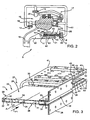
Figure 2 shows a larger-scale, partly sectioned front view, with parts removed for clarity, of a detail of theFigure 1 cable transportation system; -
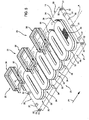
Figure 3 shows a partly sectioned view in perspective, with parts removed for clarity, of a detail of the linear electric motor of theFigure 1 cable transportation system; -
Figure 4 shows a schematic exploded view in perspective, with parts removed for clarity, of a detail of the linear electric motor inFigure 3 ; -
Figure 5 shows a larger-scale, partly sectioned plan view, with parts removed for clarity, of the detail of the linear electric motor inFigure 1 ; -
Figure 6 shows a partly exploded, partly sectioned view in perspective, with parts removed for clarity, of a detail of the linear electric motor inFigure 1 ; -
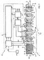
Figure 7 shows a schematic of a detail of the linear electric motor inFigure 1 , and a relative control unit. -
Number 1 inFigure 1 indicates a passenger transportation system. In theFigure 1 example,transportation system 1 is a cable transportation system, and comprises a loopeddraw cable 2; and a number oftransportation units 3 of the type suspendable from draw cable 2 - such chairs of a chairlift or cars of a cable-car system - and movable along a given path P1. -
Transportation system 1 comprises apassenger station 4; and an actuating device in turn comprising a linearelectric motor 5 for drivingtransportation units 3 intopassenger station 4. - Linear
electric motor 5 is located partly intransportation units 3 and partly inpassenger station 4. -
Passenger station 4, which in the example shown is a turnaround station, comprises apulley 6, about which drawcable 2 is looped; acontrol unit 7; and aframe 8 supportingtransportation units 3 inpassenger station 4. -
Frame 8 extends along a portion of path P1, and comprises a beam 9 which, viewed from above, is U-shaped, and supports a number of supportingstructures 10. - Linear
electric motor 5 comprises alinear stator 11, which extends along path P1, is supported by beam 9, and, viewed from above, is U-shaped. - With reference to
Figure 2 , each supportingstructure 10 supports threerails transportation unit 3 comprises asuspension arm 15, and atrolley 16 which engagesrails station 4. - Trolley 16 comprises a
coupling device 17 for selectively connectingtrolley 16 andtransportation unit 3 to drawcable 2, and which, inFigure 2 , is shown releasingdraw cable 2. - Trolley 16 has three
rollers respective rails trolley 16. Accordingly, rail 12 has a C-shaped cross section, andrespective roller 18 engages the C-section rail 12. - For each
transportation unit 3, linearelectric motor 5 comprises aslide 21 integral withtrolley 16, and which cooperates withlinear stator 11 to moverespective transportation unit 3 insidepassenger station 4. In the example shown,slide 21 is connected totrolley 16 andsuspension arm 15 by.abracket 22. - Each
transportation unit 3 traveling throughpassenger station 4 is moved byrespective slide 21, which couples withlinear stator 11 of linear electric,motor 5, which, together withrails transportation system 1. - With reference to
Figure 5 ,linear stator 11 comprises an elongated body 23 (Figure 3 ) of nonferrous material - in the example shown, glass-fibre-reinforced epoxy resin; a number ofpower windings 24 embedded inelongated body 23, and which generate a first magnetic field by passage of electric current inpower windings 24; and a number ofsensors 25 fitted toelongated body 23, and for controlling the position oftrolley 16. - In the
Figure 3 example,linear stator 11 comprisesbrackets 26 for fixingelongated body 23 to beam 9 (Figure 1 ). -
Sensors 25 are arranged with respect topower windings 24 to minimize the noise generated bypower windings 24 onsensors 25, and, in particular, are embedded inelongated body 23. -
Slide 21 comprises means for generating a second magnetic field, which interacts with the first magnetic field and movesslide 21 along path P1. - With reference to
Figure 7 ,elongated body 23 comprises a number ofmodular units 27 aligned along path P1. - With reference to
Figure 3 , eachmodular unit 27 extends along an axis of symmetry A, and is in the form of a flat plate to define a straight portion of path P1. In a variation not shown in the drawings, each modular unit is in the form of a curved plate to define a curved portion of path P1. - Each
modular unit 27 has a rectangular cross section; two opposite, parallelmain faces 28 positioned substantially horizontally; twolateral faces 29; and twoend faces 30. - With reference to
Figure 7 , eachmodular unit 27 comprises a given number of said number ofpower windings 24. More specifically, eachmodular unit 27 comprises threepower windings 24 arranged in succession and associated with respective phases R, S and T. - With reference to
Figure 5 , eachmodular unit 27 comprises a number ofpower connection elements 31 for connecting the given number ofpower windings 24 to the given number ofpower windings 24 of an adjacentmodular unit 27, and each of which is parallel to axis of symmetry A. More specifically, eachmodular unit 27 comprises sixpower connection elements 31 located alongend faces 30, and which, in the example shown, comprise three male connection elements and three female connection elements, are divided between the twoend faces 30, and are symmetric with respect to axis of symmetry A. - Each
modular unit 27 comprises a given number ofsensor 25; and a number ofcontrol connection elements 32 for controllingsensors 25 and connecting the given number ofsensors 25 ofmodular unit 27 to the given number ofsensors 25 of an adjacentmodular unit 27. More specifically, eachmodular unit 27 comprises threesensors 25; and, in the preferred embodiment,control connection elements 32 are located alongend faces 30 and divided equally between male control connection elements and female control connection elements. - In the preferred embodiment, each
modular unit 27 comprises twelvecontrol connection elements 32, so they can be arranged symmetrically with respect to axis of symmetry A along eachend face 30. Though sixcontrol connection elements 32 would be enough to connectsensors 25 ofmodular units 27, thecontrol connection elements 32 along each end face 30 are preferably doubled in the preferred embodiment of the present invention, so they can be arranged symmetrically along end faces 30. - With reference to
Figure 6 , power winding 24 comprises aconductor 33, preferably a flat conductor perpendicular to main faces 28. - With reference to
Figure 4 , power winding 24 is wound in a direction V1 about an axis A1 to form acoil 34 comprising a number of turns, and in a direction V2, opposite V1, about an axis A2 to form a.coil 35 comprising a number of turns. For the sake of simplicity, only a few of the turns of power winding 24 are shown. Eachcoil Figure 3 ), and form a gap between the two planes. - In an alternative embodiment not shown in the drawings, power winding 24 comprises a one-
turn coil 34, and a one-turn coil 35. -
Coils - With reference to
Figure 6 , eachsensor 25 comprises a control winding 36 embedded in the nonferrous material ofelongated body 23, and for detecting passage of slide 21 (Figure 3 ). In other words, eachsensor 25 is substantially defined by control winding 36 itself. When slide 21 passes close to control winding 36, the second magnetic field generated by slide 21 (Figure 7 ) links with control winding 36, which is designed to generate electric current from the interaction with the second magnetic field. - With reference to
Figure 4 , control winding 36 has a plane of symmetry U equidistant from axis A1 and axis A2. - With reference to
Figure 7 , eachmodular unit 27 comprises threecontrol windings 36, which are associated with the threepower windings 24 of the samemodular unit 27, are arranged in succession, and are therefore associated with respective phases R', S', T' coupled with respective phases R, S, T. -
Linear stator 11 is preferably divided intomodular sections 37, each comprising a number ofmodular units 27. Thepower windings 24 of the samemodular section 37 and associated with the same phase R, S, T are connected in series with one another bypower connection elements 31, and define respective groups ofpower windings 24. Similarly, thecontrol windings 36 of the samemodular section 37 and associated with the same phase R', S', T' are connected in series with one another bycontrol connection elements 32, and define respective groups of control windings 36. Both power- and control-wise, eachmodular section 37 is isolated electrically from the othermodular sections 37 by isolatingelements 38, and has connectors (not shown) for connectingpower windings 24 andsensors 25 to apower assembly 39 for poweringpower windings 24, and which is adjustable in voltage, current, frequency, and phase, and, in the example shown, comprises an inverter. -
Sensors 25 of each section are connected to acontrol unit 40, which controlspower assembly 39. -
Power connection elements 31 andcontrol connection elements 32 are symmetrical with respect to axis of symmetry A, so twomodular units 27 can be connected to form a succession of power phases R, S, T, R, S, T and a succession of control phases R', S', T', R', S', T', or a succession of power phases R, S, T, T, S, R and a succession of control phases R', S', T', T', S', R', by simply turning one of the twomodular units 27 over about axis of symmetry A. - With reference to
Figure 1 , in addition to linearelectric motor 5, the actuating device comprisescontrol unit 40, which is connected to controlunit 7 oftransportation system 1; and a number ofpower assemblies 39 equal to the number ofmodular sections 37 oflinear stator 11. An alternative embodiment, not shown in the drawings, has one power assembly for all the sections, and comprises a number of independently adjustable three-phase outputs, equal to the number of modular sections. - With reference to
Figure 1 , eachpower assembly 39 is connected torespective power windings 24 and to controlunit 40, and comprises three output terminals, each associated with one of phases R, S, T, so each group ofpower windings 24 is powered with the same frequency F, the same current intensity I, and one of phases R, S, T. - With reference to
Figure 3 , each slide 21 comprises aU-shaped plate 41 with two opposite parallel faces 42, along which are fitted two sets ofpermanent magnets 43. - The two.sets of
permanent magnets 43 are arranged opposite each other and far enough apart to fitslide 21 aboutlinear stator 11. That is, each set ofpermanent magnets 43 is substantially parallel to and faces amain face 28 ofelongated body 23, so as to form a gap betweenpermanent magnets 43 and respectivemain face 28. - With reference to
Figure 5 ,control windings 36 are equally spaced along path P1, and detect passage of transportation units 3 (Figure 1 ) along path P1. - With reference to
Figure 7 ,control unit 40 acquires transit signals STR, STS, STT; calculates speed signals SV related to speeds V, and position signals SP related to positions P ofslide 21; and compares speed signals SV with a target speed signal SVD related to a target speed VD. - With reference to
Figure 4 , control winding 36 is positioned so that the magnetic flux from power winding 24 linked to it is substantially nil. In other words, control winding 36 is so located insidelinear stator 11 that, when power winding 24 is powered, the positive magnetic flux generated bycoil coil - Each control winding 36 is designed to detect passage of
slide 21. That is, the variation in magnetic flux produced by passage ofslide 21 induces, at the terminals of control winding 36, a voltage which produces transit signal STR, STS or STT. - The
control windings 36 associated with the same phase R', S', T' and the samemodular section 37 oflinear stator 11 are connected in series, and define respective, i.e. three, groups of control windings 36 : one associated with phase R', one with.phase S', and one with phase T'. - Three transit signals STR, STS, STT, emitted by respective groups of control winding 36 and connected to control
unit 40, are therefore defined for eachmodular section 37. - With reference to
Figure 7 ,control unit 40 comprises aprocessing block 44 designed to process transit signals STR, STS and STT, and calculate speed signal SV and position signal SP. - Processing
block 44 is also designed to condition transit signals STR, STS, STT according to the speed signals SV ofslide 21 calculated the instant before. - To calculate speed signal SV, processing
block 44 processes the transit signals STR, STS, STT from respective phases R', S', T' to change from stationary coordinates to two movable coordinates : a direct coordinate, and a quadrature coordinate perpendicular to the direct coordinate.' More specifically, processingblock 44 applies first a Clarke and then a Park transform to transit signals STR, STS, STT to define a quadrature signal representing the quadrature component of the movable-coordinate system of transit signals STR, STS, STT. Speed signal SV is calculated as a function of the quadrature signal of transit signals STR, STS, STT, and more specifically is defined by the output of a proportional-integral block whose input is the quadrature signal. - Processing
block 44 calculates position signal SP on the basis of speed signal SV. -
Control unit 40 comprises a regulatingblock 45, which, for eachmodular section 37, defines regulating signals SR for arespective power assembly 39 as a function of position signal SP, speed signal SV, target speed signal SVD, and a target position signal SPD. On the basis of regulating signal, SR,power assembly 39 regulates the intensity I, frequency F, and phases R, S, T of the electric current of the groups ofpower windings 24 to achieve a speed V ofslide 21 as close as possible to target speed VD. - Linear
electric motor 5 is also designed to move transportation units 3 (Figure 1 ), along path P1 in the opposite to normal travelling direction. This is achieved by investing the phase sequence, and is useful for equally spacingtransportation units 3. - With reference to
Figure 7 ,control unit 40 comprises a reference winding 46 and a compensating block 47, which compensate for any electromagnetic noise that might deteriorate each transit signal STR, STS, STT acquired by each control winding 36. - Reference winding 46 is located to acquire a noise signal SD indicating the electromagnetic fields of any electromagnetic noise on control winding 36. To do this, reference winding 46 is located far enough away from
slide 21 andpower windings 24 to avoid picking up the magnetic fields produced by them. - Compensating block 47 receives the transit signals STR, STS, STT associated with
respective control windings 36, and noise signal SD from reference winding 46, and processes transit signals STR, STS, STT as a function of noise signal SD, to compensate for any noise. - In an alternative embodiment, reference winding 46 is eliminated, and compensating block 47 receives noise signal SD from a control winding 36 of a
modular section 37 other than the one associated at the time with the transit signals STR, STS, STT being noise-corrected. More specifically, themodular section 37 must be chosen from those not supplied with current at the time. - In an alternative embodiment not shown in the drawings, the signals from the control winding are processed digitally. To do this, each control winding, as opposed to being connected to the other control windings, is connected directly to the control unit, which disregards phases R', S', T' and processes the signals solely as a function of the spatial arrangement of the control windings associated with the transit signals. More specifically, the control unit is associated with at least two signals of two control windings, and, given two instantaneous positions, determines speed signal SV and position signal SP.
- In this variation, the control unit comprises digital circuits and a microcontroller.
- In a variation not shown, the slide comprises a metal plate instead of permanent magnets.
- In a variation of the present invention, not shown in the drawings, the sensors are not embedded in the elongated body, and the elongated body comprises sensor seats.
- In another variation of the present invention, not shown in the drawings, the sensors are not embedded in the elongated body, and.the elongated body has sensor assembly markers.
- Both the seats and markers are formed when manufacturing the elongated body in such a manner as to minimize noise generated by the power windings on the sensors.
- Though the above description refers specifically to a cable transportation system, such as a cable-car or chair-lift, the present invention also extends to any type of transportation system, e.g. a rail transportation system, driven by the actuating described in the present invention.
- Clearly, changes may be made to the system and method as described herein without, however, departing from the scope of the accompanying Claims.
Claims (24)
- A passenger transportation system comprising:- at least one rail (12, 13, 14) extending along a path (P1);- at least one trolley (16) movable along the rail (12, 13, 14);- an actuating device comprising a linear electric motor (5), in turn comprising at least one slide (21) fitted to the trolley (16), and a linear stator (11) extending at least partly along the path (P1), and comprising an elongated body (23), and a number of power windings (24) embedded in the elongated body (23); characterized by comprising a number of sensors (25) for controlling the position of the trolley (16); the sensors (25) being fitted to the elongated body (23) and so positioned as to minimize noise generated by the power windings (24) on the sensors (25).
- A transportation system as claimed in Claim 1, wherein the sensors (25) are embedded in the elongated body (23).
- A transportation system as claimed in Claim 1 or 2, wherein the elongated body (23) comprises a number of modular units (27) aligned with one another along the path (P1); each modular unit (27) extending along an axis of symmetry (A), and being in the form of a flat or curved plate to define a straight or curved portions of the path (P1) respectively.
- A transportation system as claimed in Claim 3, wherein each modular unit (27) comprises a given number of the number of power windings (24); and a number of power connection elements (31) for connecting the given number of power windings (24) to the given number of power windings (24) of an adjacent modular unit (27); each power connection element (31) being parallel to the axis of symmetry (A); each modular unit (27) preferably having two end faces (30), each facing an end face (30) of the adjacent modular unit (27); and the power connection elements (31) being located on the end faces (30) and symmetrical with respect to the axis of symmetry (A).
- A transportation system as claimed in Claim 3 or 4, wherein each modular unit (27) comprises a given number of the number of sensors (25); and a number of control connection elements (32) for connecting the given number of sensors (25) of the modular unit (27) to the given number of sensors (25) of the adjacent modular unit (27); each control connection element (32) being parallel to the axis of symmetry (A); each modular unit (27) preferably having two end faces (30), each facing an end face (30) of the adjacent modular unit (27); and the control connection elements (32) being located on the end faces (30).
- A transportation system as claimed in any one of the foregoing Claims, wherein the power winding (24) comprises at least a first coil (34) wound about a first axis (A1), and a second coil (35) wound about a second axis (A2); the first and second coil (34, 35) being connected to each other; the first coil (34) having a first winding direction (V1), and the second coil (35) having a second winding direction (V2); and the first winding direction (V1) and second winding direction (V2) being opposite.
- A transportation system as claimed in any one of the foregoing Claims, wherein the power winding (24) generates a first magnetic field by passage of current in said power windings (24); the slide (21) comprising means for generating a second magnetic field which interacts with the first magnetic field and moves the slide (21) along the path (P1); the sensor (25) comprising a control winding (36); and the second magnetic field travels through the control winding (36) when the slide (21) travels close to the control winding (36); the control winding (36) generating current by interaction with the second magnetic field.
- A transportation system as claimed in Claim 7, wherein the power winding (24) comprises at least a first coil (34) wound about a first axis (A1), and a second coil (35) wound about a second axis (A2); the first and second coil (34, 35) being connected to each other; the first coil (34) having a first winding direction (V1), and the second coil (35) having a second winding direction (V2); the first winding direction (V1) and second winding direction (V2) being opposite; and the control winding (36) is located at least partly between the first and second coil (34, 35), defines a region in space enclosed by the control winding (36) and traversed by the first magnetic field at the first and second coil (34, 35), and is designed so that the total magnetic flux of the first magnetic field of the power winding (24) linked to the control winding (36) is substantially nil.
- A transportation system as claimed in Claim 7 or 8, wherein the control winding (36) has a plane of symmetry equidistant from the first axis (A1) and second axis (A2).
- A transportation system as claimed in Claim 8, wherein the first and second coil (34, 35) lie in two parallel planes, and form a gap between the two parallel planes; the control winding (36) being located in said gap.
- A transportation system as claimed in any one of Claims 7 to 10, wherein the control winding (36) is connectable to the slide (21) to generate a transit signal (STR, STS, STT); the transit signal (STR, STS, STT) being generated by the varying magnetic flux produced by relative movement of the slide (21) with respect to the control winding (36).
- A transportation system as claimed in any one of Claims 7 to 11, and comprising a control unit (40) connected to the control windings (36) to receive the transit signals (STR, STS, STT), and designed to control the power windings (24) as a function of the transit signals (STR, STS, STT).
- A transportation system as claimed in Claim 12, wherein the control unit (40) comprises a compensating block (47) for compensating any noise in the transit signals (STR, STS, STT).
- A transportation system as claimed in Claim 12 or 13, and comprising a reference winding (46; 36) positioned so the first magnetic field of the power winding (24) does not link with the reference winding (46); and wherein the control unit (40) is connected to the reference winding (46) to receive a noise signal (SD) correlated with any noise picked up by the reference winding (46; 36).
- A transportation system as claimed in Claim 14, wherein the reference winding (46) is one of the control windings (36) associated with a non-powered power winding (24).
- A transportation system as claimed in any one of Claims 11 to 15, and comprising a power assembly (39) connected to said power winding (24) and for powering said power winding (24) with electric current having an amplitude (I), a frequency (F), and a phase (R; S; T) calculated on the basis of the transit signal (STR, STS, STT).
- A transportation system as claimed in any one of the foregoing Claims, and comprising a draw cable (2); at least one transportation unit (3) connected to the trolley (16) and connectable selectively to the draw cable (2) by a coupling device (17); and at least one passenger station (4) where the transportation unit (3) is disengaged from the draw cable (2); the linear stator (11) extending along the passenger station (4) to move the transportation unit (3) along a portion of said path (P1).
- A transportation system control method; the transportation system (1) comprising an actuating device in turn comprising a linear electric motor (5), which comprises at least one slide (21), and a linear stator (11) extending at least partly along a path (P1), comprising an elongated body (23) and in turn comprising at least one power winding (24) embedded in the elongated body; and a sensor (25) comprising at least one control winding (36); the slide (21) and the linear stator (11) being magnetically connectable to induce movement of the slide (21) along the path (P1); and the method comprising the steps of detecting a transit signal (STR, STS, STT) by means of the control winding (36), and determining a position (P) or speed (V) of the slide (21) as a function of the transit signal (STR, STS, STT).
- A method as claimed in Claim 18, and comprising the step of powering the power winding (24) as a function of the transit signal (STR, STS, STT).
- A method as claimed in Claim 18 or 19, and comprising the steps of locating the control winding (36) so that the total magnetic flux produced by the power winding (24) and linked to the control winding (36) is substantially nil.
- A method as claimed in any one of Claims 18 to 20, and comprising the steps of detecting any noise by means of a reference winding (46; 36) located so that a first magnetic field generated by the power winding (24) does not link with the reference winding; and processing the transit signal (STR, STS, STT) on the basis of any detected noise.
- A method as claimed in any one of Claims 18 to 21, and comprising the step of controlling the linear electric motor (5) on the basis of the position of the slide (21) and/or the speed (V) of the slide (21).
- A method as claimed in any one of Claims 18 to 22, wherein the linear electric motor (5) comprises three control windings (36), each associated with a phase (R', S', T') and supplying a respective one of the transit signals (STR, STS, STT); the method comprising the steps of processing the transit signals (STR, STS, STT) to define a quadrature signal representing the quadrature component of the transit signals (STR, STS, STT) in a movable-coordinate system; and defining a speed (V) of the slide (21) on the basis of the quadrature signal of the three transit signals (STR, STS, STT).
- A method as claimed in any one of Claims 18 to 23, wherein the step of detecting a transit signal (STR, STS, STT) comprises detecting a voltage at the terminals of the control winding (36) in response to varying magnetic flux produced by passage of the slide (21) with the control winding (36).
Applications Claiming Priority (2)
| Application Number | Priority Date | Filing Date | Title |
|---|---|---|---|
| ITMI2009A002273A IT1397880B1 (en) | 2009-12-23 | 2009-12-23 | TRANSPORTATION SYSTEM FOR PASSENGERS HANDLING AND RELATIVE CONTROL METHOD. |
| PCT/IB2010/003328 WO2011077233A1 (en) | 2009-12-23 | 2010-12-22 | Passenger transportation system and relative control method |
Publications (2)
| Publication Number | Publication Date |
|---|---|
| EP2516236A1 EP2516236A1 (en) | 2012-10-31 |
| EP2516236B1 true EP2516236B1 (en) | 2014-02-12 |
Family
ID=43086293
Family Applications (1)
| Application Number | Title | Priority Date | Filing Date |
|---|---|---|---|
| EP10812901.6A Active EP2516236B1 (en) | 2009-12-23 | 2010-12-22 | Passenger transportation system and relative control method |
Country Status (5)
| Country | Link |
|---|---|
| US (3) | US8849482B2 (en) |
| EP (1) | EP2516236B1 (en) |
| ES (1) | ES2453270T3 (en) |
| IT (1) | IT1397880B1 (en) |
| WO (1) | WO2011077233A1 (en) |
Families Citing this family (10)
| Publication number | Priority date | Publication date | Assignee | Title |
|---|---|---|---|---|
| IT1397880B1 (en) * | 2009-12-23 | 2013-02-04 | Rolic Invest Sarl | TRANSPORTATION SYSTEM FOR PASSENGERS HANDLING AND RELATIVE CONTROL METHOD. |
| ITBZ20110036A1 (en) * | 2011-08-02 | 2013-02-03 | Hans Costabiei | HANDLING SYSTEM FOR ROPE VEHICLES |
| AT515098B1 (en) | 2013-11-28 | 2015-06-15 | Innova Patent Gmbh | Plant for the transport of persons |
| CN104709103A (en) * | 2014-10-10 | 2015-06-17 | 阮自恒 | Aerodyne of electric pole rail |
| WO2017172786A1 (en) | 2016-03-28 | 2017-10-05 | Hyperloop Technologies, Inc. | Metamaterial null flux magnetic bearing system |
| DE102017002955B4 (en) * | 2017-03-27 | 2022-06-09 | Karl Dobler | Method of operating a cable car and cable car as such |
| US11097750B2 (en) * | 2017-12-22 | 2021-08-24 | Leitner S.P.A. | Cable transportation system and method for transporting people or goods and clamp for a vehicle of a cable transportation system |
| IT201800006234A1 (en) * | 2018-06-12 | 2019-12-12 | ROPE TRANSPORT SYSTEM | |
| DE102020125162A1 (en) | 2020-09-25 | 2022-03-31 | Intrasys Gmbh Innovative Transportsysteme | Ride for popular amusement with vehicle-fixed winding component |
| AT525546B1 (en) * | 2021-11-04 | 2023-05-15 | Kaunertaler Gletscherbahnen Ges M B H | Device and method for parking a hanger of a cable car system |
Family Cites Families (17)
| Publication number | Priority date | Publication date | Assignee | Title |
|---|---|---|---|---|
| BE771162A (en) * | 1970-08-17 | 1972-02-11 | Automatisme Cie Gle | MOBILE LOCATION SYSTEM ON A SPECIFIC TRAJECTORY |
| GB1371143A (en) * | 1972-01-24 | 1974-10-23 | Tracked Hovercraft Ltd | Ground transportation systems and tracks and vehicles therefor |
| US3834316A (en) * | 1972-03-09 | 1974-09-10 | Jung A Lokomotivfab Gmbh | Two rail suspension railway with a linear motor |
| DE2328366A1 (en) * | 1973-06-04 | 1974-12-19 | Uerdingen Ag Waggonfabrik | HAENGEBAHN, ESPECIALLY FOR PERSONNEL IN CITY CENTERS |
| US3974778A (en) * | 1974-08-12 | 1976-08-17 | Walt Disney Productions | Speed control system |
| US4061089A (en) * | 1975-09-02 | 1977-12-06 | Elbert Morgan Sawyer | Personal rapid transit system |
| US4862809A (en) * | 1983-07-12 | 1989-09-05 | Cimarron Technology Ltd. | Supports for railway linear synchronous motor |
| US4836344A (en) * | 1987-05-08 | 1989-06-06 | Inductran Corporation | Roadway power and control system for inductively coupled transportation system |
| US5158021A (en) * | 1990-12-28 | 1992-10-27 | Kajima Corporation | Ski lift with variable speed linear motor drive and emergency stop apparatus responsive to power loss to the drive |
| ATE126489T1 (en) * | 1993-05-26 | 1995-09-15 | Fahrleitungsbau Gmbh | DEVICE FOR DETERMINING THE POSITION OF A VEHICLE MOVABLE ON A RAIL. |
| US5492066A (en) * | 1993-07-30 | 1996-02-20 | Shinko Electric Co., Ltd. | Transport system |
| AU6341200A (en) * | 1999-07-02 | 2001-01-22 | Magnemotion, Inc. | System for inductive transfer of power, communication and position sensing to a guideway-operated vehicle |
| AU2425401A (en) * | 1999-11-23 | 2001-06-04 | Magnemotion, Inc. | Modular linear motor tracks and methods of fabricating same |
| WO2004055607A2 (en) * | 2002-12-16 | 2004-07-01 | Koninklijke Philips Electronics N.V. | Apparatus for processing an object with high position accurancy |
| DE10331866B4 (en) * | 2003-07-14 | 2008-11-13 | Minebea Co., Ltd. | Device for controlling a coil arrangement with electrically variable inductance, and switching power supply |
| ITMI20071618A1 (en) | 2007-08-03 | 2009-02-04 | Rolic Invest Sarl | ROPE TRANSPORTATION SYSTEM AND METHOD OF OPERATION OF THE SAME |
| IT1397880B1 (en) * | 2009-12-23 | 2013-02-04 | Rolic Invest Sarl | TRANSPORTATION SYSTEM FOR PASSENGERS HANDLING AND RELATIVE CONTROL METHOD. |
-
2009
- 2009-12-23 IT ITMI2009A002273A patent/IT1397880B1/en active
-
2010
- 2010-12-22 ES ES10812901.6T patent/ES2453270T3/en active Active
- 2010-12-22 US US13/518,279 patent/US8849482B2/en active Active
- 2010-12-22 EP EP10812901.6A patent/EP2516236B1/en active Active
- 2010-12-22 WO PCT/IB2010/003328 patent/WO2011077233A1/en not_active Ceased
-
2014
- 2014-09-15 US US14/486,634 patent/US9487219B2/en active Active
-
2016
- 2016-10-18 US US15/296,615 patent/US9919614B2/en active Active
Also Published As
| Publication number | Publication date |
|---|---|
| US9487219B2 (en) | 2016-11-08 |
| IT1397880B1 (en) | 2013-02-04 |
| US20150000552A1 (en) | 2015-01-01 |
| US20130054057A1 (en) | 2013-02-28 |
| US9919614B2 (en) | 2018-03-20 |
| WO2011077233A1 (en) | 2011-06-30 |
| US8849482B2 (en) | 2014-09-30 |
| ITMI20092273A1 (en) | 2011-06-24 |
| EP2516236A1 (en) | 2012-10-31 |
| US20170036562A1 (en) | 2017-02-09 |
| ES2453270T3 (en) | 2014-04-07 |
Similar Documents
| Publication | Publication Date | Title |
|---|---|---|
| US9919614B2 (en) | Passenger transportation system and relative control method | |
| CN112400267B (en) | Contactless power supply device and contactless power supply system | |
| CN106477437B (en) | Elevator wireless power supply | |
| AU2018303466B2 (en) | Switch for a track for guiding transportation of a vehicle | |
| US20120187873A1 (en) | Linear motor driving system and linear motor control method | |
| CN102009832B (en) | Mobile body system and control method of the mobile body | |
| US20100031846A1 (en) | Magnetic levitation vehicle with at least one magnetic system | |
| KR940005452A (en) | Maglev Transfer Device | |
| MXPA04012176A (en) | Device for inductively transmitting electric power. | |
| CN106926744A (en) | A kind of magnetic suspension train | |
| US10594245B2 (en) | Controlling long-stator linear motor coils of a long-stator linear motor stator | |
| EP3989432B1 (en) | System and method of monitoring disturbance force in an independent cart system, compensation of said disturbance force | |
| KR101221486B1 (en) | Space division multiplexed power supply and collector device | |
| US7832534B2 (en) | Device for transmitting electrical energy from the track to the vehicle of a magnetic levitation railway | |
| JP2020025436A5 (en) | ||
| US8733252B2 (en) | Electric monorail part carrier | |
| JP4304625B2 (en) | Tracked cart system | |
| JP2012016106A (en) | Alignment system of noncontact power supply device | |
| WO2007108586A1 (en) | System of railway vehicle using linear motor and non-contact electric power supply system | |
| US7786685B2 (en) | Linear motor and method for operating a linear motor | |
| KR101329363B1 (en) | Estimanted position apparatus of magnetic levitation train for phase control in propelled invertor of the train based by ls-lsm | |
| JPH11168805A (en) | Car carrier traveling system | |
| KR100944154B1 (en) | Trolley bogie system | |
| CN119567879A (en) | Non-contact running magnetic levitation transportation system and control method thereof | |
| JPH101904A (en) | AC electromagnet type magnetic attracting levitation linear motor conveyor |
Legal Events
| Date | Code | Title | Description |
|---|---|---|---|
| PUAI | Public reference made under article 153(3) epc to a published international application that has entered the european phase |
Free format text: ORIGINAL CODE: 0009012 |
|
| 17P | Request for examination filed |
Effective date: 20120619 |
|
| AK | Designated contracting states |
Kind code of ref document: A1 Designated state(s): AL AT BE BG CH CY CZ DE DK EE ES FI FR GB GR HR HU IE IS IT LI LT LU LV MC MK MT NL NO PL PT RO RS SE SI SK SM TR |
|
| DAX | Request for extension of the european patent (deleted) | ||
| GRAP | Despatch of communication of intention to grant a patent |
Free format text: ORIGINAL CODE: EPIDOSNIGR1 |
|
| RAP1 | Party data changed (applicant data changed or rights of an application transferred) |
Owner name: ROLIC INTERNATIONAL S.A R.L. |
|
| INTG | Intention to grant announced |
Effective date: 20130603 |
|
| RIN1 | Information on inventor provided before grant (corrected) |
Inventor name: SONNERER, WALTER Inventor name: CONTE, GIUSEPPE |
|
| GRAP | Despatch of communication of intention to grant a patent |
Free format text: ORIGINAL CODE: EPIDOSNIGR1 |
|
| INTG | Intention to grant announced |
Effective date: 20130822 |
|
| GRAS | Grant fee paid |
Free format text: ORIGINAL CODE: EPIDOSNIGR3 |
|
| GRAA | (expected) grant |
Free format text: ORIGINAL CODE: 0009210 |
|
| AK | Designated contracting states |
Kind code of ref document: B1 Designated state(s): AL AT BE BG CH CY CZ DE DK EE ES FI FR GB GR HR HU IE IS IT LI LT LU LV MC MK MT NL NO PL PT RO RS SE SI SK SM TR |
|
| REG | Reference to a national code |
Ref country code: GB Ref legal event code: FG4D |
|
| REG | Reference to a national code |
Ref country code: CH Ref legal event code: EP |
|
| REG | Reference to a national code |
Ref country code: AT Ref legal event code: REF Ref document number: 652011 Country of ref document: AT Kind code of ref document: T Effective date: 20140215 |
|
| REG | Reference to a national code |
Ref country code: IE Ref legal event code: FG4D |
|
| REG | Reference to a national code |
Ref country code: DE Ref legal event code: R096 Ref document number: 602010013594 Country of ref document: DE Effective date: 20140327 |
|
| REG | Reference to a national code |
Ref country code: ES Ref legal event code: FG2A Ref document number: 2453270 Country of ref document: ES Kind code of ref document: T3 Effective date: 20140407 |
|
| REG | Reference to a national code |
Ref country code: CH Ref legal event code: NV Representative=s name: HEPP WENGER RYFFEL AG, CH |
|
| REG | Reference to a national code |
Ref country code: NL Ref legal event code: VDEP Effective date: 20140212 |
|
| REG | Reference to a national code |
Ref country code: LT Ref legal event code: MG4D |
|
| PG25 | Lapsed in a contracting state [announced via postgrant information from national office to epo] |
Ref country code: LT Free format text: LAPSE BECAUSE OF FAILURE TO SUBMIT A TRANSLATION OF THE DESCRIPTION OR TO PAY THE FEE WITHIN THE PRESCRIBED TIME-LIMIT Effective date: 20140212 Ref country code: IS Free format text: LAPSE BECAUSE OF FAILURE TO SUBMIT A TRANSLATION OF THE DESCRIPTION OR TO PAY THE FEE WITHIN THE PRESCRIBED TIME-LIMIT Effective date: 20140612 Ref country code: NO Free format text: LAPSE BECAUSE OF FAILURE TO SUBMIT A TRANSLATION OF THE DESCRIPTION OR TO PAY THE FEE WITHIN THE PRESCRIBED TIME-LIMIT Effective date: 20140512 |
|
| PG25 | Lapsed in a contracting state [announced via postgrant information from national office to epo] |
Ref country code: FI Free format text: LAPSE BECAUSE OF FAILURE TO SUBMIT A TRANSLATION OF THE DESCRIPTION OR TO PAY THE FEE WITHIN THE PRESCRIBED TIME-LIMIT Effective date: 20140212 Ref country code: CY Free format text: LAPSE BECAUSE OF FAILURE TO SUBMIT A TRANSLATION OF THE DESCRIPTION OR TO PAY THE FEE WITHIN THE PRESCRIBED TIME-LIMIT Effective date: 20140212 Ref country code: PT Free format text: LAPSE BECAUSE OF FAILURE TO SUBMIT A TRANSLATION OF THE DESCRIPTION OR TO PAY THE FEE WITHIN THE PRESCRIBED TIME-LIMIT Effective date: 20140612 Ref country code: NL Free format text: LAPSE BECAUSE OF FAILURE TO SUBMIT A TRANSLATION OF THE DESCRIPTION OR TO PAY THE FEE WITHIN THE PRESCRIBED TIME-LIMIT Effective date: 20140212 Ref country code: SE Free format text: LAPSE BECAUSE OF FAILURE TO SUBMIT A TRANSLATION OF THE DESCRIPTION OR TO PAY THE FEE WITHIN THE PRESCRIBED TIME-LIMIT Effective date: 20140212 |
|
| PG25 | Lapsed in a contracting state [announced via postgrant information from national office to epo] |
Ref country code: BE Free format text: LAPSE BECAUSE OF FAILURE TO SUBMIT A TRANSLATION OF THE DESCRIPTION OR TO PAY THE FEE WITHIN THE PRESCRIBED TIME-LIMIT Effective date: 20140212 Ref country code: HR Free format text: LAPSE BECAUSE OF FAILURE TO SUBMIT A TRANSLATION OF THE DESCRIPTION OR TO PAY THE FEE WITHIN THE PRESCRIBED TIME-LIMIT Effective date: 20140212 Ref country code: LV Free format text: LAPSE BECAUSE OF FAILURE TO SUBMIT A TRANSLATION OF THE DESCRIPTION OR TO PAY THE FEE WITHIN THE PRESCRIBED TIME-LIMIT Effective date: 20140212 Ref country code: RS Free format text: LAPSE BECAUSE OF FAILURE TO SUBMIT A TRANSLATION OF THE DESCRIPTION OR TO PAY THE FEE WITHIN THE PRESCRIBED TIME-LIMIT Effective date: 20140212 |
|
| PG25 | Lapsed in a contracting state [announced via postgrant information from national office to epo] |
Ref country code: EE Free format text: LAPSE BECAUSE OF FAILURE TO SUBMIT A TRANSLATION OF THE DESCRIPTION OR TO PAY THE FEE WITHIN THE PRESCRIBED TIME-LIMIT Effective date: 20140212 Ref country code: RO Free format text: LAPSE BECAUSE OF FAILURE TO SUBMIT A TRANSLATION OF THE DESCRIPTION OR TO PAY THE FEE WITHIN THE PRESCRIBED TIME-LIMIT Effective date: 20140212 Ref country code: DK Free format text: LAPSE BECAUSE OF FAILURE TO SUBMIT A TRANSLATION OF THE DESCRIPTION OR TO PAY THE FEE WITHIN THE PRESCRIBED TIME-LIMIT Effective date: 20140212 Ref country code: CZ Free format text: LAPSE BECAUSE OF FAILURE TO SUBMIT A TRANSLATION OF THE DESCRIPTION OR TO PAY THE FEE WITHIN THE PRESCRIBED TIME-LIMIT Effective date: 20140212 |
|
| REG | Reference to a national code |
Ref country code: DE Ref legal event code: R097 Ref document number: 602010013594 Country of ref document: DE |
|
| PG25 | Lapsed in a contracting state [announced via postgrant information from national office to epo] |
Ref country code: PL Free format text: LAPSE BECAUSE OF FAILURE TO SUBMIT A TRANSLATION OF THE DESCRIPTION OR TO PAY THE FEE WITHIN THE PRESCRIBED TIME-LIMIT Effective date: 20140212 Ref country code: SK Free format text: LAPSE BECAUSE OF FAILURE TO SUBMIT A TRANSLATION OF THE DESCRIPTION OR TO PAY THE FEE WITHIN THE PRESCRIBED TIME-LIMIT Effective date: 20140212 |
|
| PLBE | No opposition filed within time limit |
Free format text: ORIGINAL CODE: 0009261 |
|
| STAA | Information on the status of an ep patent application or granted ep patent |
Free format text: STATUS: NO OPPOSITION FILED WITHIN TIME LIMIT |
|
| 26N | No opposition filed |
Effective date: 20141113 |
|
| REG | Reference to a national code |
Ref country code: DE Ref legal event code: R097 Ref document number: 602010013594 Country of ref document: DE Effective date: 20141113 |
|
| REG | Reference to a national code |
Ref country code: DE Ref legal event code: R082 Ref document number: 602010013594 Country of ref document: DE Representative=s name: MUELLER-BORE & PARTNER PATENTANWAELTE PARTG MB, DE |
|
| REG | Reference to a national code |
Ref country code: GB Ref legal event code: 732E Free format text: REGISTERED BETWEEN 20150305 AND 20150311 |
|
| REG | Reference to a national code |
Ref country code: CH Ref legal event code: PUE Owner name: ROPFIN B.V., NL Free format text: FORMER OWNER: ROLIC INTERNATIONAL S.A R.L., LU |
|
| REG | Reference to a national code |
Ref country code: DE Ref legal event code: R082 Ref document number: 602010013594 Country of ref document: DE Representative=s name: MUELLER-BORE & PARTNER PATENTANWAELTE PARTG MB, DE Effective date: 20150306 Ref country code: DE Ref legal event code: R081 Ref document number: 602010013594 Country of ref document: DE Owner name: ROPFIN B.V., NL Free format text: FORMER OWNER: ROLIC INTERNATIONAL S.A R.L., LUXEMBOURG, LU Effective date: 20150306 Ref country code: DE Ref legal event code: R081 Ref document number: 602010013594 Country of ref document: DE Owner name: LEITNER S.P.A., VIPITENO, IT Free format text: FORMER OWNER: ROLIC INTERNATIONAL S.A R.L., LUXEMBOURG, LU Effective date: 20150306 |
|
| REG | Reference to a national code |
Ref country code: ES Ref legal event code: PC2A Owner name: ROPFIN B.V. Effective date: 20150512 |
|
| PG25 | Lapsed in a contracting state [announced via postgrant information from national office to epo] |
Ref country code: SI Free format text: LAPSE BECAUSE OF FAILURE TO SUBMIT A TRANSLATION OF THE DESCRIPTION OR TO PAY THE FEE WITHIN THE PRESCRIBED TIME-LIMIT Effective date: 20140212 |
|
| REG | Reference to a national code |
Ref country code: FR Ref legal event code: TP Owner name: ROPFIN B.V., NL Effective date: 20150527 |
|
| PG25 | Lapsed in a contracting state [announced via postgrant information from national office to epo] |
Ref country code: LU Free format text: LAPSE BECAUSE OF FAILURE TO SUBMIT A TRANSLATION OF THE DESCRIPTION OR TO PAY THE FEE WITHIN THE PRESCRIBED TIME-LIMIT Effective date: 20141222 |
|
| REG | Reference to a national code |
Ref country code: IE Ref legal event code: MM4A |
|
| PG25 | Lapsed in a contracting state [announced via postgrant information from national office to epo] |
Ref country code: IE Free format text: LAPSE BECAUSE OF NON-PAYMENT OF DUE FEES Effective date: 20141222 |
|
| REG | Reference to a national code |
Ref country code: FR Ref legal event code: PLFP Year of fee payment: 6 |
|
| REG | Reference to a national code |
Ref country code: AT Ref legal event code: PC Ref document number: 652011 Country of ref document: AT Kind code of ref document: T Owner name: ROPFIN B.V., NL Effective date: 20151218 |
|
| PG25 | Lapsed in a contracting state [announced via postgrant information from national office to epo] |
Ref country code: SM Free format text: LAPSE BECAUSE OF FAILURE TO SUBMIT A TRANSLATION OF THE DESCRIPTION OR TO PAY THE FEE WITHIN THE PRESCRIBED TIME-LIMIT Effective date: 20140212 |
|
| PG25 | Lapsed in a contracting state [announced via postgrant information from national office to epo] |
Ref country code: MC Free format text: LAPSE BECAUSE OF FAILURE TO SUBMIT A TRANSLATION OF THE DESCRIPTION OR TO PAY THE FEE WITHIN THE PRESCRIBED TIME-LIMIT Effective date: 20140212 |
|
| PG25 | Lapsed in a contracting state [announced via postgrant information from national office to epo] |
Ref country code: GR Free format text: LAPSE BECAUSE OF FAILURE TO SUBMIT A TRANSLATION OF THE DESCRIPTION OR TO PAY THE FEE WITHIN THE PRESCRIBED TIME-LIMIT Effective date: 20140513 Ref country code: BG Free format text: LAPSE BECAUSE OF FAILURE TO SUBMIT A TRANSLATION OF THE DESCRIPTION OR TO PAY THE FEE WITHIN THE PRESCRIBED TIME-LIMIT Effective date: 20140212 |
|
| PG25 | Lapsed in a contracting state [announced via postgrant information from national office to epo] |
Ref country code: HU Free format text: LAPSE BECAUSE OF FAILURE TO SUBMIT A TRANSLATION OF THE DESCRIPTION OR TO PAY THE FEE WITHIN THE PRESCRIBED TIME-LIMIT; INVALID AB INITIO Effective date: 20101222 Ref country code: TR Free format text: LAPSE BECAUSE OF FAILURE TO SUBMIT A TRANSLATION OF THE DESCRIPTION OR TO PAY THE FEE WITHIN THE PRESCRIBED TIME-LIMIT Effective date: 20140212 Ref country code: MT Free format text: LAPSE BECAUSE OF FAILURE TO SUBMIT A TRANSLATION OF THE DESCRIPTION OR TO PAY THE FEE WITHIN THE PRESCRIBED TIME-LIMIT Effective date: 20140212 |
|
| REG | Reference to a national code |
Ref country code: FR Ref legal event code: PLFP Year of fee payment: 7 |
|
| REG | Reference to a national code |
Ref country code: FR Ref legal event code: PLFP Year of fee payment: 8 |
|
| REG | Reference to a national code |
Ref country code: DE Ref legal event code: R082 Ref document number: 602010013594 Country of ref document: DE Representative=s name: MUELLER-BORE & PARTNER PATENTANWAELTE PARTG MB, DE Ref country code: DE Ref legal event code: R081 Ref document number: 602010013594 Country of ref document: DE Owner name: LEITNER S.P.A., VIPITENO, IT Free format text: FORMER OWNER: ROPFIN B.V., LEIMUIDEN, NL |
|
| REG | Reference to a national code |
Ref country code: CH Ref legal event code: PUE Owner name: LEITNER S.P.A., IT Free format text: FORMER OWNER: ROPFIN B.V., NL |
|
| REG | Reference to a national code |
Ref country code: ES Ref legal event code: PC2A Owner name: LEITNER S.P.A. Effective date: 20180313 |
|
| REG | Reference to a national code |
Ref country code: GB Ref legal event code: 732E Free format text: REGISTERED BETWEEN 20180301 AND 20180307 |
|
| REG | Reference to a national code |
Ref country code: AT Ref legal event code: PC Ref document number: 652011 Country of ref document: AT Kind code of ref document: T Owner name: LEITNER S.P.A., IT Effective date: 20180509 |
|
| PG25 | Lapsed in a contracting state [announced via postgrant information from national office to epo] |
Ref country code: MK Free format text: LAPSE BECAUSE OF FAILURE TO SUBMIT A TRANSLATION OF THE DESCRIPTION OR TO PAY THE FEE WITHIN THE PRESCRIBED TIME-LIMIT Effective date: 20140212 |
|
| REG | Reference to a national code |
Ref country code: FR Ref legal event code: TP Owner name: LEITNER S.P.A., IT Effective date: 20180605 |
|
| PG25 | Lapsed in a contracting state [announced via postgrant information from national office to epo] |
Ref country code: AL Free format text: LAPSE BECAUSE OF FAILURE TO SUBMIT A TRANSLATION OF THE DESCRIPTION OR TO PAY THE FEE WITHIN THE PRESCRIBED TIME-LIMIT Effective date: 20140212 |
|
| PGFP | Annual fee paid to national office [announced via postgrant information from national office to epo] |
Ref country code: ES Payment date: 20210122 Year of fee payment: 11 |
|
| REG | Reference to a national code |
Ref country code: ES Ref legal event code: FD2A Effective date: 20230301 |
|
| PG25 | Lapsed in a contracting state [announced via postgrant information from national office to epo] |
Ref country code: ES Free format text: LAPSE BECAUSE OF NON-PAYMENT OF DUE FEES Effective date: 20211223 |
|
| P01 | Opt-out of the competence of the unified patent court (upc) registered |
Effective date: 20230524 |
|
| REG | Reference to a national code |
Ref country code: CH Ref legal event code: U11 Free format text: ST27 STATUS EVENT CODE: U-0-0-U10-U11 (AS PROVIDED BY THE NATIONAL OFFICE) Effective date: 20260101 |
|
| PGFP | Annual fee paid to national office [announced via postgrant information from national office to epo] |
Ref country code: GB Payment date: 20251223 Year of fee payment: 16 |
|
| PGFP | Annual fee paid to national office [announced via postgrant information from national office to epo] |
Ref country code: AT Payment date: 20251218 Year of fee payment: 16 |
|
| PGFP | Annual fee paid to national office [announced via postgrant information from national office to epo] |
Ref country code: IT Payment date: 20251112 Year of fee payment: 16 |
|
| PGFP | Annual fee paid to national office [announced via postgrant information from national office to epo] |
Ref country code: FR Payment date: 20251223 Year of fee payment: 16 |
|
| PGFP | Annual fee paid to national office [announced via postgrant information from national office to epo] |
Ref country code: DE Payment date: 20251229 Year of fee payment: 16 |
|
| PGFP | Annual fee paid to national office [announced via postgrant information from national office to epo] |
Ref country code: CH Payment date: 20260101 Year of fee payment: 16 |